1
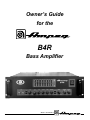
Owner’s Guide
for the
B4R
Bass Amplifier
Made in the U.S.A. by
B4R Bass Amplifier
TABLE OF CONTENTS
Important Safeguards and Precautions . . . . . . . . . . . . . . .2
Introduction . . . . . . . . . . . . . . . . . . . . . . . . . . . . . . . . . . . .3
Features . . . . . . . . . . . . . . . . . . . . . . . . . . . . . . . . . . . . . .3
The Front Panel Controls and Their Use . . . . . . . . . . . . .4,5
The Rear Panel . . . . . . . . . . . . . . . . . . . . . . . . . . . . . . .6,7
Connections: Mono Bridged . . . . . . . . . . . . . . . . . . . . . .8
Dual Mono . . . . . . . . . . . . . . . . . . . . . . . . .8
Biamp, Full Range and Lows . . . . . . . . . . .8
Biamp, Highs and Lows . . . . . . . . . . . . . . .9
Biamp With Second Amplifier . . . . . . . . . . .9
Some Suggested Settings . . . . . . . . . . . . . . . . . . . . . . . .10
Rack Mounting . . . . . . . . . . . . . . . . . . . . . . . . . . . . . . . .10
Troubleshooting . . . . . . . . . . . . . . . . . . . . . . . . . . . . . . . .11
System Block Diagram . . . . . . . . . . . . . . . . . . . . . . . . . .11
Technical Specifications . . . . . . . . . . . . . . . . . . .back cover
Important Safeguards and Precautions:
All Ampeg products are designed for continuous safe operation, as long as common sense is used and steps are taken to
help avoid certain problems. Abiding by the following rules can help prevent damage to your amplifier, yourself and others.
• The amplifier is equipped with a three-pronged AC power cord. To reduce the risk of electrical shock, NEVER
remove or otherwise attempt to defeat the ground pin of the power cord.
• Connect the amplifier ONLY to a properly grounded AC outlet of the proper voltage for your amp.
• Avoid sudden temperature extremes, rain and moisture. Also, avoid sudden and intense impact. (If the unit
has been subjected to any of the preceding abuses, have it looked at by an authorized service center.)
• NEVER set the amplifier on a support that might give out under its weight.
• Whenever using tall or stacked speaker cabinets, use them ONLY on a level surface. NEVER set tall or stacked
cabinets on a surface with more than a five degree incline since tipping or falling could occur, possibly causing serious injuries.
• Always keep the total speaker impedance at or above the rated load.
• Unplug the amplifier before cleaning it. NEVER spray liquid cleaners onto the amplifier. Wipe it with a slightly
dampened, lint-free cloth to remove dirt and film.
• Don’t use the amplifier if it has sustained damage to the chassis, controls, or power cord. Refer the unit to an
authorized service center for inspection.
• Amplifiers capable of producing high volume levels are also capable of inflicting permanent hearing loss or
damage, if the exposure to such levels is prolonged. Such damage is progressive and irreversible!
CAUTION
ATTENTION
VORSICHT
RISK OF ELECTRIC SHOCK
DO NOT OPEN
RISQUE D'ELECTROCUTION
NE PAS OUVRIR
ELEKTRISCHE SCHLAGGEFAHR
NICHT OFFENEN
CAUTION: TO REDUCE THE RISK OF ELECTRIC SHOCK,
DO NOT REMOVE COVER.
NO USER-SERVICEABLE PARTS INSIDE.
REFER SERVICING TO QUALIFIED SERVICE PERSONNEL.
ATTENTION: POUR REDUIRE D'ELECTROCUTION NE PAS
ENLEVER LE COUVERCLE. AUCUNE PIECE INTERNE N'EST REPRABLE
PAR L'UTILISATEUR. POUR TOUTE REPARATION, S'ADRESSER A UN
TECHNICIEN QUALIFIE.
VORSICHT: ZUR MINIMIERUNG ELEKTRISCHER SCHLAGGEFAHR NICHT
DEN DECKEL ABENHMEN. INTERNE TEILE KONNEN NICHT VOM
BENUTZER GEWARTET WERDEN. DIE WARTUNG IS QUALIFIZIERTEM
WARTUNGSPERSONAL ZU UBERLASSEN.
THIS EQUIPMENT HAS BEEN DESIGNED AND ENGINEERED TO PROVIDE SAFE AND RELIABLE OPERATION. IN ORDER TO PROLONG THE LIFE OF THE UNIT AND PREVENT ACCIDENTAL DAMAGES OR INJURY, PLEASE FOLLOW THESE PRECAUTIONARY GUIDELINES:
WARNING: TO REDUCE THE RISK OF ELECTRIC SHOCK, DO NOT OPEN CHASSIS; DO NOT DEFEAT OR REMOVE THE GROUND PIN OF THE POWER CORD; CONNECT ONLY TO A PROPERLY GROUNDED AC POWER OUTLET.
CAUTION: TO REDUCE THE RISK OF FIRE OR ELECTRIC SHOCK, DO NOT EXPOSE THIS EQUIPMENT TO RAIN OR MOISTURE.
CAUTION: NO USER-SERVICEABLE PARTS INSIDE. REFER SERVICING TO QUALIFIED SERVICE PERSONNEL.
CAUTION: OUR AMPLIFIERS ARE CAPABLE OF PRODUCING HIGH SOUND PRESSURE LEVELS. CONTINUED EXPOSURE TO HIGH SOUND PRESSURE LEVELS CAN CAUSE PERMANENT
HEARING IMPAIRMENT OR LOSS. USER CAUTION IS ADVISED AND EAR PROTECTION IS RECOMMENDED IF UNIT IS OPERATED AT HIGH VOLUME. The chart below shows the U.S.
Government Occupational Safety and Health Administration (OSHA) regulations which were in effect at the time of this publication for permissible noise exposure, per 29CRF1910, Table G-16.
SOUND LEVEL dBA
SLOW RESPONSE
DURATION PER DAY
IN HOURS
SOUND LEVEL dBA
SLOW RESPONSE
DURATION PER DAY
IN HOURS
90
92
95
97
100
8
6
4
3
2
102
105
110
115
1-1/2
1
1/2
1/4 or less
According to OSHA, any exposure in excess of those listed above could result in some hearing loss.
EXPLANATION OF
GRAPHICAL SYMBOLS:
2
"DANGEROUS VOLTAGE"
= "DANGER HAUTE TENSION"
"GEFAHLICHE SPANNUNG"
"IT IS NECESSARY FOR THE USER TO REFER TO THE INSTRUCTION MANUAL"
= "REFERREZ-VOUS AU MANUAL D'UTILISATION"
"UNBEDINGT IN DER BEDIENUNGSANLEITUNG NACHSCHLAGEN"
B4R Bass Amplifier
An Introduction to your new Ampeg B4R Bass Amplifier
Thank you for making one of the best choices you will ever make for your musical career – choosing one
of the finest bass amps available, the Ampeg B4R. This versatile and powerful bass amplifier delivers up
to 1350 watts of unsurpassed musical power, and offers several outstanding features.
All of the features and controls of your B4R are covered in detail within the pages of this owner’s guide.
We recommend going over them before you use the amplifier.
Features
In the world of high performance bass amps, Ampeg amplifiers stand alone. In true Ampeg tradition, the
B4R offers you more power, performance and flexibility than any other bass amplifier in its class. The outstanding features of your new amplifier, features which set it apart from the competition, are listed below.
• DUAL SEPARATE POWER AMPLIFIERS: Operate in true stereo or mono bridged
mode for even greater output power (page 6,8,9).
• BIAMP CAPABLE: Adjustable crossover frequency control. Low-to-high frequency
balance control (page 5,8,9).
• 5-POSITION STYLE CONTROL: Take your pick from five different tone variations to
best suit your playing style (page 4).
• TEXTURE CONTROL: Changes your tone for a more aggressive sound (page 4).
• 9-BAND GRAPHIC EQ: Switchable at front panel or with a footswitch, you can use
this as a “second channel” for bass solos, or to shape your sound to your own exacting standards. An independent level control lets you adjust the Graphic EQ volume.
(page 5).
• EFFECTS MIX: Varies the amount of external effects mixed into the signal (page 4,5).
• TUNER OUT JACK: Allows connection to an electronic tuner and provides an “always
live” monitor feed even when the output is muted (page 7).
• HEAVY-DUTY SPEAKER JACKS: For more reliable connections at higher outputs
and for mono bridged connections: dual binding posts (domestic units) or Speakon®
jacks (export units) (page 6,7).
• BALANCED AND UNBALANCED LINE OUTPUTS: Independent level control.
Balanced XLR and unbalanced 1/4” output jacks. Switchable pre or post EQ (page 7).
• EFFECTS LOOP: Connect your effects here for increased intensity and quieter operation (page 7).
• POWER AMP IN/PREAMP OUT: Two separate loops, one for each channel: a separate preamp may be connected to the Power Amp In jack, and the Preamp Out jack
may be connected to a slave amp (page 6,7).
• FOOTSWITCH CONTROL: Use a footswitch to activate the Graphic EQ and the Mute
feature (page 6,7).
• CIRCUIT BREAKER PROTECTION: A heavy duty resettable circuit breaker provides
protection against fault conditions (page 6).
Speakon® is a registered trademark of Neutrik AG.
3
B4R Bass Amplifier
The Front Panel Controls and Their Use
18
33Hz
80Hz
150Hz
300Hz
600Hz
900Hz
+12dB
0
-12dB
INPUT
GAIN
STYLE
BASS
ULTRA MID
7
8
9
MUTE
0dB
-15dB
1
2
1. 0dB INPUT: The signal output from an instrument (active
or passive – typically passive) or a line level signal may be
connected here by means of a shielded instrument cable. The
signal at this jack is sent into the preamp at full amplitude.
3
PEAK
4
5
6
7. STYLE: This five-position switch allows you to vary the
tone of the amplifier. The following table lists each of the different settings – experiment with the Style and other EQ controls (#8,9,10,18,19) for the results which suit you best.
2. -15dB INPUT: The signal output from an instrument
(active or passive – typically active) or a line level signal may
be connected here by means of a shielded instrument cable.
The signal at this jack is padded 15dB before it is sent into
the preamp.
POSITION 1: Fully “scooped” mids (mid cut)
3. MUTE: This switch, when depressed, mutes all outputs
except the Tuner Out (#41). A footswitch can also control
muting if the Mute switch on the front panel is left in the “out”
position. (The front panel switch is still active with a
footswitch connected.) This is excellent for tuning your bass
with an electronic tuner without having to adjust any levels or
turn down your house volume.
POSITION 5: Basically flat with low end roll off – for
loud playing without “muddiness”
4. TEXTURE: This switch adds a “tube emulation” stage
which changes the tone for a more aggressive sound. Using
the Texture switch, you can overdrive the amplifier without
typical (and harsh-sounding) solid state clipping.
5. GAIN: This control sets the level of the signal entering the
preamp stage. Adjust this control until the Peak LED (#6)
flashes on strong signal peaks (but is not illuminated constantly while playing). To obtain the best signal to noise ratio,
set the Gain control as described above and adjust the
Master (#14) to obtain the desired volume level.
6. PEAK LED: This LED will illuminate when the signal
entering the preamp stage is near the clipping level. Adjust
the Gain control (#5) until a strong signal from your instrument causes this LED to flicker.
4
TEXTURE
POSITION 2: Traditional passive tone setting
POSITION 3: Basically flat
POSITION 4: Boosted high end
8. BASS: This is the primary low frequency control which
allows 12dB of cut or boost at 50Hz. The low frequency output is flat at the center position.
9. ULTRA MID: This is the primary midrange control which
allows 7dB of cut at 400Hz or boost at 800Hz. The midrange
output is flat at the center position.
10. TREBLE: This is the primary high frequency control
which allows 18dB of cut or boost at 5kHz. The high frequency output is flat at the center position.
11. EFFECTS MIX: This control varies the mix between the
direct (dry) signal and the effects (wet) when the effects loop
(#39,40) is used. Full counterclockwise results in all direct
signal (no effect) and full clockwise gives all effect and no
direct signal. The clockwise position is equivalent to a series
effects loop and should be used with such devices as limiters
and equalizers.
B4R Bass Amplifier
The Front Panel Controls and Their Use – Con’t.
19
2kHz
5kHz
8kHz
20
21
22
LEVEL
POWER
ACTIVE
TREBLE
EFFECTS MIX
MASTER
FREQUENCY
BALANCE
300Hz
FLAT
GRAPHIC EQ
DRY
WET
50Hz
LIMIT DEFEAT
10
11
12 13
1kHz
LO
HI
LIMIT
14 15
16
12. GRAPHIC EQ: This switch activates the graphic equalizer. When a footswitch is used, this switch is disabled.
13. LIMIT DEFEAT: The B4R employs internal limiter circuits
to help keep the power amplifier’s output clean at extreme
volume levels. (All amplifiers may begin to clip their output
signals as they approach maximum output levels, resulting in
potentially speaker-damaging distortion.) These circuits may
be disabled by depressing this switch. This may result in an
increase in output power, but also increases the possibility of
distortion. Use discretion whenever playing with the Limit circuits off.
14. MASTER: This control sets the overall output level of the
amplifier. For the lowest possible noise level, adjust the Gain
control as described in #5 and use this control to obtain the
desired volume level.
15. LIMIT LED: This LED will flash any time the internal limit
circuit is called upon to keep the amplifier’s output signal
clean. This indicates that the amplifier is nearing full output
and the limiter is keeping it from clipping the output signal.
16. FREQUENCY: This control sets the crossover point
between the Biamp High and Biamp Low Outputs when
using the amplifier in the biamp mode.
17. BALANCE: This control adjusts the relative level
between the low and high frequency biamp signals when
using the amplifier in the biamp mode.
17
18. 9-BAND GRAPHIC EQ: These sliders control the amplitude of the frequencies indicated above each control. The
center position of each control is flat: sliding the control
upward will increase the output level of that frequency; sliding the control downward will decrease it.
The Graphic EQ can be used in two ways: 1) To fine tune your
sound, make small adjustments at the desired frequencies and
leave the EQ on throughout the entire session. (This is great for
adapting to varying room acoustics when going from club to club,
etc.) 2) For a completely different sound, make larger adjustments
and only activate the EQ when you want a “second channel” sound
(such as during bass solos).
19. LEVEL: This is the output volume control for the Graphic
EQ and only affects the signal when the EQ is engaged. If
the EQ’d signal is too soft, slide the Level control up; if it’s too
loud, slide the control down.
20. POWER LED: This LED glows green when the Power
switch (#22) is ON.
21. ACTIVE LED: This LED illuminates when the EQ is on.
22. POWER: This heavy-duty rocker switch applies the
power to the amplifier: the amp is ON when the top of the
switch is depressed, OFF when the bottom of the switch is
depressed.
5
B4R Bass Amplifier
The Rear Panel
33
BI-AMP
HIGH
OUTPUT
*MONO BRIDGE: 1+ HOT, 2+ RETURN
BIAMP: 1+ LOW HOT, 1– LOW RETURN
2+ HIGH HOT, 2– HIGH RETURN
CHANNEL
B
–
MONO
BRIDGE
LOW
OUTPUT
+
CHANNEL
A
350 WATTS/CH. @ 4 OHMS, STEREO
500 WATTS/CH. @ 2 OHMS, STEREO
2 OHM MINIMUM LOAD
1000 WATTS @ 4 OHMS, MONO BRIDGE
4 OHM MINIMUM LOAD
CHANNEL
B
23
24
23. CIRCUIT BREAKER: The B4R employs an AC line circuit
breaker to help protect against damage due to excessive current demands. If the amplifier stops working, check the circuit
breaker. If it has opened, the button will be protruding and
showing a contrasting color. You can reset the circuit breaker
by pushing it in until it latches. The breaker must cool down for
a short time before the button will latch. If the circuit breaker
opens repeatedly, have the amplifier checked by a qualified
service person.
24. AC LINE IN: Firmly insert the supplied AC power cord into
this socket until it is fully seated. Plug the male end of the cord
into a grounded AC outlet. DO NOT DEFEAT THE GROUND
PRONG OF THE AC PLUG!
25. SPEAKER OUTPUTS: The 1/4” jacks offer a convenient
method of connecting to speaker cabinets using cables terminated with 1/4” plugs. However, when using the amplifier at or
near its full output power, using the five-way binding posts
(domestic units) or Speakon® jacks (export units) is recommended. The binding posts/Speakon® jacks must be used when operating in the Mono Bridged mode. (See pages 8 and 9.)
26. FULL RANGE/BIAMP: This switch determines how the
signal is sent to the internal amplifiers. In the Full Range position (switch out), a full range signal is sent to both amp chan-
6
SPEAKER
OUTPUTS
CHANNEL
A
25
nels. In the Biamp position (switch in), the low frequencies are
sent to Channel A and the high frequencies are sent to
Channel B. (See pages 8 and 9.)
NOTE: When Biamping, the Stereo/Mono switch (#27) must be
set to Stereo. (See pages 8 and 9.)
27. STEREO/MONO: This switch sets the operating mode of
the amplifier. In the “out” position the amplifier is in the Stereo
Mode; with the switch in the “in” position the amplifier is in the
Mono Bridged Mode. (See pages 8 and 9.)
28,30. POWER AMP INPUTS: These jacks connect directly
to the power amp for use with external preamps. When using
external sources, connect the OUTPUT of the sources to
these jacks using shielded instrument cables to feed the signals into the power amp sections. The internal signal is disconnected when a plug is inserted. In the Mono Mode,
Channel A = Input. In the Biamp Mode, Channel A = Low Input,
Channel B = High Input. (See pages 8 and 9.)
29,31. PREAMP OUTPUTS These jacks are direct preamp
outputs for use with external power amplifiers, mixing boards,
external effects, etc. Connect the external unit inputs to these
jacks using shielded instrument cables.
Speakon® is a registered trademark of Neutrik AG.
B4R Bass Amplifier
The Rear Panel – Con’t.
33
34
35 36
BI-AMP
37
38
39
LINE OUT
40
41
EFFECTS LOOP
PRE/
POST
H
UT
LOW
OUTPUT
LEVEL
GND
LIFT
BAL.
UNBAL.
1+ HOT, 1–
O
GE
+
SEND
CHANNEL
A
TUNER
OUT
1+ HOT, 1–
CHANNEL
A
OHMS, STEREO
OHMS, STEREO
UM LOAD
S, MONO BRIDGE
UM LOAD
KER
UTS
RETURN
B4R
CH. B
CH. A
FULL
RANGE
POWER AMP B
BI-AMP
POWER AMP
INPUT
POWER AMP A
PREAMP
OUTPUT
POWER AMP
INPUT
PREAMP
OUTPUT
FT. SW.
GRAPHIC EQ/
MUTE
STEREO
MONO
BIAMP HIGH
INPUT
26 27 28
BIAMP LOW/
MONO BRIDGE INPUT
29
30
31
32. FOOTSWITCH: Connect a two button footswitch to this
jack for remote Mute and EQ On/Off control. On the stereo
1/4” plug, the tip controls Mute and the ring controls EQ
On/Off. When a footswitch is connected, the Mute switch
(#3) can still be used; however, the EQ switch (#12) is disabled.
32
reduce residual hum and buzz sometimes picked up in line
out signal cables. The ground is lifted when the switch is
depressed.
33. BIAMP HIGH/LOW OUTPUTS: When using the amplifier in the biamp mode, the Biamp High Out jack carries the
high frequency signal and the Biamp Low Out jack carries
the low frequency signal. (See pages 8 and 9.)
37,38. LINE OUT JACKS: These jacks supply a pre-Master,
line level signal for connection to a house mixing board,
recording console or external amplifier(s). The XLR-type jack
(#37) provides a balanced signal; the 1/4” jack (#38) provides an unbalanced signal. The signal level at these jacks is
controlled by the Line Out Level control (#34) and is governed by the Pre/Post switch (#35).
34. LINE OUT LEVEL: This controls the strength of the signal at the Line Out jacks (#37,38) and works independently
from the Master control (#14).
39. EFFECTS LOOP RETURN: When using external
effects, connect the effect’s output into this jack using a
shielded instrument cable.
35. LINE OUT PRE/POST SWITCH: The signal at the Line
Out jacks can be set to either Pre or Post EQ with this switch.
With the switch in the OUT position, the signal at the jacks
will be Pre-EQ. This is a direct output not affected by any
preamp tone settings. With the switch IN, the signal is PostEQ and is controlled and modified by the tone controls,
Graphic EQ and the effects loop.
40. EFFECTS LOOP SEND: When using an external signal
processor, connect this jack to the input of the effect using a
shielded instrument cable.
36. LINE OUT GROUND LIFT: This switch disconnects the
ground pin of the line Out XLR jack (#37), which may help
41. TUNER OUT: This jack is provided for connection to an
electronic tuner and is always “live,” even when the Mute
switch (#3) is engaged, allowing for “silent tuning” as well as
a monitor feed which remains active when the house mix is
muted.
7
B4R Bass Amplifier
Connections:
In the example shown below, the B4R’s two internal power amplifiers are bridged together to produce maximum output power.
Set the Stereo/Mono Bridge switch to the IN (Mono Bridged) position and connect the system as follows:
Mono
Bridged
B4R
FULL RANGE
CABINET(S)
MONO
BRIDGE
MONO
BRIDGE
1
1
IN
(MONO)
TO
INPUT
JACK
NOTE: BE
ABSOLUTLEY
CERTAIN THAT
THE CABINET(S)
ARE ABLE TO
HANDLE THE
EXTREMELY
HIGH OUTPUT
POWER OF THE
AMP IN THIS
MODE!
1: Connect a heavy duty speaker cable terminated with a Speakon® connector or dual banana plugs from the B4R’s Mono Bridge / Biamp Output jack
to the input jack of a speaker cabinet capable of handling the extremely high output power. (Speakon®: pin 1 +, 2 +; Banana: Mono +, Mono –.)
In the example shown below, the B4R’s two internal power amplifiers will each power a set of full range cabinets.
Set the Stereo/Mono Bridge switch to the OUT (Stereo) position and connect the system as follows:
Dual
Mono
B4R
PWR
AMP B
PWR
AMP B
PWR
AMP A
PWR
AMP A
FULL RANGE
CABINET(S)
2
2
1
1
OUT
TO
INPUT
JACK
(STEREO)
FULL RANGE
CABINET(S)
TO
INPUT
JACK
1: Connect a speaker cable from the B4R’s Power Amp A Speaker Output jack to the input jack(s) of a set of full range speakers.
2: Connect a speaker cable from the B4R’s Power Amp B Speaker Output jack to the input jack(s) of another set of full range speakers.
In the example shown below, the B4R’s two internal power amplifiers will power both a full range cabinet and a low frequency cabinet. The crossover
point is determined by the Biamp Frequency control (#16).
Set the Stereo/Mono Bridge switch to the OUT (Stereo) position and connect the system as follows:
BIAMP
LO OUT
B4R
Biamp: Full
Range / Lows
PWR
AMP B
1
PWR
AMP A
PWR
AMP B
3
3
2
OUT
(STEREO)
PWR
AMP A
PWR
AMP A
P.A. IN
FULL RANGE
CABINET(S)
2
TO
INPUT
JACK
LOW FREQ.
CABINET(S)
TO
INPUT
JACK
1: Connect a shielded cable from the B4R’s Biamp Low Out jack to its Power Amp A Power Amp In jack.
2: Connect a speaker cable from the B4R’s Power Amp A Speaker Output jack to the input jack of the low frequency cabinet(s).
3: Connect a speaker cable from the B4R’s Power Amp B Speaker Output jack to the input jack of the full range cabinet(s).
8
B4R Bass Amplifier
In the example shown below, the B4R’s two internal power amplifiers will power both a high frequency cabinet and a low frequency cabinet. The crossover
point is determined by the Frequency control (#16).
Set the Stereo/Mono Bridge switch to the OUT (Stereo) position and connect the system as follows:
Biamp:
Highs / Lows
B4R
PWR
AMP B
PWR
AMP A
PWR
AMP B
PWR
AMP A
1
3
IN
3
2
HIGH FREQ.
CABINET(S)
(BIAMP)
2
OUT
TO
INPUT
JACK
(STEREO)
LOW FREQ.
CABINET(S)
TO
INPUT
JACK
1: Set the Full Range/Biamp switch to the IN (Biamp) position.
2: Connect a speaker cable from the B4R’s Power Amp A Speaker Output jack to the input jack of the low frequency cabinet(s).
3: Connect a speaker cable from the B4R’s Power Amp B Speaker Output jack to the input jack of the high frequency cabinet(s).
In the example shown below, the B4R’s two internal power amplifiers are bridged together and will power the low frequency cabinet(s). A second amplifier will
be used to power the high frequency cabinet(s). The crossover point is determined by the Frequency control (#16).
Set the Stereo/Mono Bridge switch to the IN (Mono Bridge) position and connect the system as follows:
Biamp with a
Second Amp
B4R
BIAMP BIAMP
HI OUT LO OUT
1
2
MONO
BRIDGE
MONO
BRIDGE
4
4
PWR
AMP A
P.A. IN
(MONO
BRIDGE)
HIGH FREQ.
CABINET(S)
IN
POWER AMP
(SVP-1500)
MONO
BRIDGE
(MONO)
TO
INPUT
JACK
3
LOW FREQ.
CABINET(S)
CH A
INPUT
IN
TO
INPUT
JACK
(MONO)
1: Connect a shielded cable from the B4R’s Biamp High Output jack to the Input jack of the High Frequency power amplifier.
2: Connect a shielded cable from the B4R’s Biamp Low Output jack to its Power Amp A Input jack.
3: Connect the high frequency power amp’s Speaker Output jack to the input jack(s) of the high frequency cabinet(s). (Observe amplifier’s minimum
load rating!)
4: Connect a heavy duty speaker cable terminated with a Speakon® connector or dual banana plugs from the B4R’s Mono Bridge / Biamp Output jack
to the input jack of the low frequency speaker cabinet. (Speakon®: pin 1 +, 2 –; Banana: Mono –, Mono +.)
Speakon® is a registered trademark of Neutrik AG.
9
B4R Bass Amplifier
Some Suggested Settings
ROCK:
GAIN
STYLE
BASS
ULTRA MID
TREBLE
STYLE
BASS
ULTRA MID
TREBLE
STYLE
BASS
ULTRA MID
TREBLE
STYLE
BASS
ULTRA MID
TREBLE
STYLE
BASS
ULTRA MID
TREBLE
MUTE
Since so many variables
affect the actual sound of any
system, the following settings are
offered as starting points to help
you find the exact sounds your
playing demands. When using
the B4R, please keep in mind the
following points:
IN
TEXTURE
JAZZ:
• The Graphic EQ can be used
to further fine-tune these basic
suggested setting, to extend
the frequency response of the
cabinet being used, to compensate for room acoustics, or
to act like a “second channel”
GAIN
MUTE
• The Gain control should be
adjusted until the peak LED
flashes on strong signals. (This
level will vary, depending on
your instrument and playing
style.)
• The Master control should be
set to produce the appropriate
output volume level.
PEAK
OUT
TEXTURE
COUNTRY:
PEAK
GAIN
MUTE
IN
OUT
TEXTURE
BRIGHT:
PEAK
GAIN
MUTE
OUT
IN
TEXTURE
FUNK “POPPING:”
PEAK
GAIN
MUTE
IN
OUT
TEXTURE
PEAK
Rack Mounting
When mounting the amplifier into a rack, the four bottom feet should be removed to maintain the three rack space height of the amplifier. Be sure to keep the feet and their attachment bolts for future use. If the feet are reinstalled, never use screws which will protrude
farther into the amplifier than the original hardware.
The rack must be a high quality enclosure capable of securely supporting the weight of the amplifier. Tighten the mounting screws
securely through the amplifier’s face plate, into the rack rails. Check the rack and mounting screws occasionally to ensure a continually safe and secure installation.
10
B4R Bass Amplifier
Troubleshooting
In the unlikely event that your B4R should malfunction, take a few minutes to troubleshoot it before you call for service. You can save yourself time and money by doing it yourself, and often the problem is something quite simple.
NO SOUND
POOR SOUND
LEDs LIGHT
LEDs DON'T LIGHT
Check bass, cables
Check amp controls, check
for signal from bass
Check AC outlet
POOR SOUND
OUTLET OK NO POWER
Check speaker(s)
NO SOUND
SOUND OK
SOUND OK
Check power cord,
fuse, power switch
Listen for hum
NO HUM
HUM
Check speaker
Unplug bass,
touch tip of cable
Check house fusebox
or circuit breaker
SPEAKER(S) OK,
POOR SOUND
OK
SPEAKER(S)
DEFECTIVE
Replace speaker(s)
POOR SOUND
SOUND OK
Speaker OK
NO CHANGE
SOUND OK
Replace cable
NO CHANGE
SEE BELOW
SEE BELOW
If the problem isn’t covered above, or if the steps lead you here, then contact your Ampeg dealer for service information. Also, you should refer your amp to an authorized service center if it gets dropped, has liquid spilled into it, or sustains
damage to its power cord (see page 2).
System Block Diagram
PEAK
LED
TEXTURE
TUNER
OUT
0dB
INPUT
TONE CIRCUITS
EQ IN
MUTE
GAIN
9 BAND
GRAPHIC
EQ
BASS ULTRA MID TREBLE
-15dB
INPUT
(X9)
f
STYLE
LEVEL
(SLIDERS)
"DOMESTIC"
BI-AMP
UNBAL
LINE OUT
LIMIT
DEFEAT
POWER
AMP A
LOW
OUT
FREQ
PRE
HIGH
OUT
LIMITER
BAL
BAL
LINE
OUT
LINE
POST OUT
PRE/
POST
LEVEL
BLK
(–)
"EXPORT"
SPKR
OUT
(A)
1+
1–
POWER
AMP IN
(A/MONO)
BRIDGE MONO
GROUND
LIFT
SPKR
OUT
(A)
BINDING
POSTS
(A)
RED
(+)
2–
SPEAKON ®
JACK
(A)
2+
STEREO
LIMIT
LED
PREAMP
OUT
(A/MONO)
EFFECTS
SEND
STEREO/
BRIDGED
EFFECTS
MIX
POWER
AMP B
LIMITER
STEREO
BIAMP
SPKR
OUT
(B)
POWER
AMP IN
(B)
PREAMP
OUT
(B)
2–
2+
SPEAKON
JACK
(MONO
BRIDGE/
BIAMP)
®
SPEAKON
JACK
(B)
®
1+
SPKR
OUT
(B)
EFFECTS
RETURN
BRIDGE
MONO
1+
1–
MASTER
1–
BINDING
POSTS
(B)
RED
(+)
2–
2+
BLK
(–)
Speakon® is a registered trademark of Neutrik AG.
FULL RANGE
11
B4R Bass Amplifier
Technical Specifications
OUTPUT POWER RATING
1350 Watts Mono-Bridged @ 4 Ohms (1000 Watts Continuous)
840 Watts Mono-Bridged @ 8 Ohms (680 Watts Continuous)
2 x 675 Watts @ 2 Ohms (500 Watts Continuous)
2 x 420 Watts @ 4 Ohms (340 Watts Continuous)
2 x 255 Watts @ 8 Ohms (205 Watts Continuous)
TONE CONTROL RANGE
Bass:
Ultra Mid:
Treble:
GRAPHIC EQ LEVEL
GRAPHIC EQ RANGE
33Hz:
80Hz:
150Hz:
300Hz:
600Hz:
900Hz:
2kHz:
5kHz:
8kHz:
SIGNAL TO NOISE RATIO
FOOTSWITCH JACK
POWER REQUIREMENTS
Domestic:
Export:
SIZE AND WEIGHT
±12dB @ 50Hz
+7dB @ 800Hz, -7dB @400Hz
±18dB @ 5kHz
±6dB
±15dB
±10dB
±8dB
±8dB
±8dB
±8dB
±8dB
±10dB
±12dB
75dB typical
Graphic EQ On/Off, Mute On/Off – Tip = Mute, Ring = EQ
120VAC, 60Hz, 800VA
100/115VAC 50/60Hz, 800VA
230VAC, 50/60Hz, 800VA
19/17.4”W x 5.6”H (with feet) x 15.5”D; 43 lbs
Ampeg reserves the right to change specifications without notice.
www.ampeg.com
Ampeg is proudly Made in America. ©1999 SLM Electronics, 1400 Ferguson Avenue, St. Louis, MO 63133 U.S.A.
P/N 47-618-03 . 07/99