1
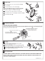
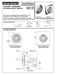
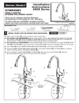
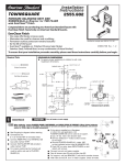
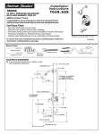
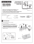
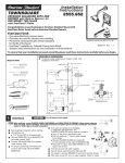
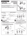
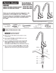
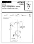
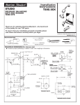
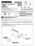
Installation
Instructions
4501
4501S
SYMPHONY
PRESSURE BALANCING BATH
AND SHOWER TRIM KITS
Thank you for selecting American-Standard...the benchmark
of fine quality for over 100 years.
To ensure that your installation proceeds smoothly--please
read these instructions carefully before you begin.
Certified to comply with ANSI A112.18.1
M 9 6 8 8 0 5 R E V. 1 . 4
ROUGHING-IN DIMENSIONS
To assure proper positioning in relation
to wall, note roughing-in dimensions.
1-5/8" TO 3-1/4"
FINISHED WALL
1/2" NPT
3-5/8" REF.
OPTIONAL TO FINISHED
FLOOR USUALLY
BETWEEN 65'' AND 80''
INLETS 3-3/8"
5-1/2" REF.
SHR. 1/2" NPT
"SEE ILLUSTRATION "
3-3/8"
74" FOR HEAD
CLEARANCE
INLETS 1/2" NPT
6-3/4"
TUB PORT 1/2" NPT
18" OPTIONAL
3-5/8"
'
THREADED INLETS
1/2" NPT''
5-1/8" REF.
4"
TOP OF TUB RIM
BOTTOM OF TUB
1
ROUGHING-IN
CAUTION
Turn off water at main supply.
NOTE When soldering, remove PLASTER GUARD, CARTRIDGES and CHECK STOPS (IF PRESENT). When finished soldering,
flush valve body, replace cartridges, check stops (if present) and plaster guard to continue installation. Use thread
sealant or Teflon tape on threaded connections.
See Roughing-in diagram before starting.
Connections are:
1/2" female NPT for threaded inlets
Connect RISER PIPE (1) to MANIFOLD (2)
top outlet marked "SHR".
Connect TUB FILLER PIPE (3) at bottom
outlet marked "TUB".
For proper positioning the finished wall
must be within side wall of PLASTER
GUARD (4).
If the valve is installed on a fiberglass
or other thin wall application, the
PLASTER GUARD (4) can be used as a support.
5
7
1
Cut a 4" dia. hole in the shower stall.
2
Drill two additional 1" holes to allow access
HOT
to the stops.
Remove PLASTER GUARD (4), rotate 90˚
so that indicated screw holes fit MANIFOLD (2).
Push CAP on valve, place ESCUTCHEON on and
3
attach with screws.
Connect hot and cold water supplies.
Cap off shower pipe (5) and tub filler pipe (6).
For support, use pipe BRACES (7) secured to wooden braces.
With valve turned off, turn on water supplies. Check for leaks.
COLD
6
4
2
3
INSTALL TRIM
4
When finished tiling the wall, remove PLASTER GUARD (3).
Push on CAP (1).
Mount ESCUTCHEON (2) and with SCREWS (7).
5
Install HANDLE (8) by pushing it onto CARTRIDGE STEM (9)
and tightening SET SCREW (10) from below with 2.5mm
Hex Wrench supplied. Insert INDEX BUTTON (11).
Remove cap from tub supply and plug from shower pipe.
2
9
Install SHOWER ARM with FLANGE (4) and SHOWER HEAD (5).
1
7
Install DIVERTER SPOUT (6).
8
10
11
6
3
ADJUST HOT LIMIT STOP
HOT LIMIT SAFETY STOP ADJUSTMENT
By restricting handle rotation and limiting the amount of hot water allowed to mix with the cold, the HOT LIMIT SAFETY STOP
reduces risk of accidental scalding. To set the maximum hot water temperature of your faucets, all you need to do is adjust
the setting on the HOT LIMIT SAFETY STOP.
"A"
ADJUSTMENT WHEN WATER IS TOO HOT
"A" PRY RED RING FORWARD AND ROTATE
COUNTER-CLOCKWISE ONE CLICK
0
TEMPERATURE SETTING NUMBERS
1
2
3
"B"
4
5
6
ADJUSTMENT WHEN WATER IS TOO COLD
PRY RED RING FORWARD AND ROTATE CLOCKWISE
"B"
1
"RED RING"- HOT LIMIT SAFETY STOP
4
SERVICE
1
If faucet drips, operate handle several times from "off"
to "on". Do not apply excessive force.
Clogged CARTRIDGE (4) inlets may cause reduced flow in "full
on" hot or cold. To clean inlets, first turn off water supply, then:
Remove HANDLE (1), CAP (2) and CARTRIDGE (4). Clean inlets and MANIFOLD (5).
Reassemble CARTRIDGE (4), alternately tightening SCREWS (3).
Replace CAP (2) and HANDLE (1). Check flow.
5
4
2
3
5
CARE INSTRUCTIONS:
DO: SIMPLY RINSE THE PRODUCT CLEAN WITH CLEAR WATER. DRY WITH A SOFT COTTON FLANNEL CLOTH.
DO NOT: DO NOT CLEAN THE PRODUCT WITH SOAPS, ACID, POLISH, ABRASIVES, HARSH CLEANERS, OR A
CLOTH WITH A COARSE SURFACE.
M 9 6 8 8 0 5 R E V. 1 . 4