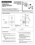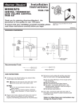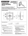
1
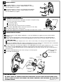
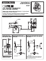
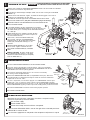
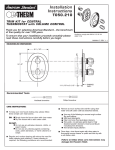
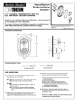
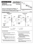
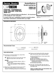
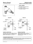
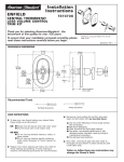
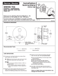
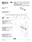
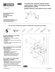
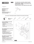
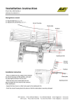
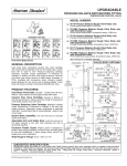
Installation
Instructions
ENFIELD
T373.742
T373.741
T373.740
BATH/SHOWER
TRIM KITS
Thank you for selecting American-Standard...the benchmark
of fine quality for over 100 years.
To ensure that your installation proceeds smoothly--please
read these instructions carefully before you begin.
ATTENTION:
If TRIM T373.742 or diverter tub spout is used
make sure TWIN ELL (B) P/N 8888.120 is
connected to valve body as indicated in roughingin sketch.
1
Certified to comply with ANSI A112.18.1
M968294 REV 1.1
CAUTION: Protect finish on SHOWER ARM,
SHOWER HEAD and TUB SPOUT when installing.
INSTALL
TRIM
When finished tiling the wall, remove PLASTER GUARD (A) and
turn off water supply.
Attach STEM ADAPTER (1) to TEMPERATURE CONTROL (2) valve
stem with SELF TAPPING SCREW (3). Attach HANDLE SCREW (4)
to VOLUME CONTROL ADAPTER (5).
TWIN ELL
TWIN ELL P/N 8888.120 can be ordered as
shown in the American Standard List Price Book
ROUGHING-IN DIMENSIONS
Installation for Bath/Shower,
Shower only, or Valve only Trim.
Dimensions are for reference.
Mount ESCUTCHEON (7) to valve body with SCREWS (8).
Push DIAL PLATE (9) over CAPS (6) and into the four alignment holes in
ESCUTCHEON (7) and snap into place.
FINISHED WALL
1/2" NPT
Push CAPS (6) onto TEMPERATURE CONTROL (2) and VOLUME
CONTROL ADAPTER (5).
Remove PIPE CAP (10) and PIPE CAP (11) from shower pipe and tub filler pipe.
1" MIN.
5-1/8" REF.
Install SHOWER ARM (17) with SHOWER ARM ESCUTCHEON (18),
SHOWER HEAD (12) and TUB FILLER SPOUT (13) by threading onto
pipe nipples. Use teflon tape or pipe sealant on pipe threads.
18
7-7/8" REF.
17
OPTIONAL TO FINISHED
FLOOR USUALLY
BETWEEN 74'' AND 80''
FOR HEAD CLEARANCE
12
4"
9-1/2"
TOP
10
5
18" OPTIONAL
PLASTER GUARD (A)
4
1" MIN.
6
4"
1/2" NPT
5-3/4" REF.
TOP OF
TUB RIM
TWIN ELL (B)
Required Tools
2
3
1
8
Flat Blade Screwdriver
11
Adjustable Wrench
Channel Locks
(4) ALIGNMENT
HOLES FOR
DIAL PLATE
9
BOTTOM OF TUB
Phillips Screwdriver
7
13
2
INSTALL HANDLES
2
Align CROSS HANDLE (1) and push onto VOLUME CONTROL
ADAPTER (2). Tighten set screw in CROSS HANDLE (1) securley
with HEX WRENCH (3) supplied.
1
Align LEVER HANDLE (4) and push onto TEMPERATURE CONTROL
ADAPTER (5). Tighten set screw in LEVER HANDLE (4) securley
with HEX WRENCH (3) supplied.
4
5
3
3
TRANSPOSED SUPPLY PIPING
OR BACK TO BACK INSTALLATION
CHECK STOP
(BLUE TO RED)
Should the hot and cold water supply pipes have been transposed making
adjustment impossible, proceed as follows:
Shut off water supply.
Remove handle and rim
Remove check stops and re-install them transposed.
Important note: RED CHECK STOP is now on the right of the mixer body
and the BLUE CHECK STOP is now on the left.
Turn the water supply back on and perform the temperature adjustment in step 2.
4
CHECK STOP
(RED TO BLUE)
TEMPERATURE ADJUSTMENT
Loosen set screw in LEVER HANDLE ASSEMBLY (1) with HEX WRENCH (2) supplied and pull off LEVER HANDLE
ASSEMBLY (1).
Check that arrow marking B points vertically upward. If not, push the BLACK CLAMP on the SECURING RING to
the right, pull off KNOB MOUNT (3) and reinstall KNOB MOUNT (3) with arrow "B" vertically upward. See Figure 1.
SET HOT LIMIT STOP
The maximum mixed water temperature is set at 109 F at the factory. This setting can be changed if desired.
Remove the TEMPERATURE LIMIT STOP (H shaped Black Plastic part). Reinstall it at the desired notch as indicated in
the diagram to limit the maximum mixed water temperature to 104 F or 112 F.
For 100 F adjustment, turn the water supply on. Turn KNOB MOUNT (3) until the spout temperature is 100 F. Check
that arrow "A" on the KNOB MOUNT (3) still points vertically upward after adjusting the thermostat to 100 F.
If not, pull out the RED LOCKING DEVICE. Remove KNOB MOUNT (3) by pulling it towards you while standing directly in
front of the valve.
Reinstall the KNOB MOUNT (3) with arrow marking "A" vertically upward.
ARROWS AT 12 O'CLOCK
POSITION
Reinstall RED LOCKING DEVICE.
(Vertically Upward)
3
Figure 1
KNOB MOUNT
BLACK
CLAMP
ARROW
"A"
ARROW
"B"
3
104
1
109
112
TEMPERATURE
LIMIT STOP
RED LOCKING
DEVICE
2
CARE INSTRUCTIONS:
DO: SIMPLY RINSE THE PRODUCT CLEAN WITH CLEAR WATER. DRY WITH A SOFT COTTON FLANNEL CLOTH.
DO NOT: CLEAN THE PRODUCT WITH SOAPS, ACID, POLISH, ABRASIVES, HARSH CLEANERS, OR A CLOTH WITH
A COARSE SURFACE
M968294 REV 1.1
ENFIELD
M962289-YYY0A
SHOWER ARM
AND ESCUTCHEON
BATH/SHOWER
TRIM KITS
MODEL NUMBER
T373.742
T373.741
T373.740
M953565-YYY0A
SHOWER HEAD
M962365-YYY0A
ESCUTCHEON AND SCREWS
M909625-YYY0A
DIAL PLATE
M918318-0070A
HANDLE SCREW
M950119-YYY0A
CROSS HANDLE
ASSEMBLY
907090-YYY0A
ESCUTCHEON CAP
A918434-YYY0A
ESCUTCHEON SCREWS
M950118-YYY0A
LEVER HANDLE
ASSEMBLY
M918990-0070A
SELF TAPPING
HANDLE SCREW
M918038-0070A
HANDLE ADAPTER
M950220-YYY0A
DIVERTER SPOUT (IPS)
M962256-YYY0A
DIVERTER SPOUT
REPAIR KIT
Replace the "YYY" with
appropriate finish code
CHROME
POLISHED NICKEL
BLACKENED BRONZE
POLISHED BRASS
SATIN
002
008
068
099
295
HOT LINE FOR HELP
For toll-free information and answers to your questions, call:
1-800 442-1902
Weekdays 8:00 a.m. to 8:00 p.m. EST
IN CANADA 1-800-387-0369 (TORONTO 1-905-306-1093)
Weekdays 8:00 a.m. to 7:00 p.m. EST
Product names listed herein are trademarks of American Standard Inc.
© American Standard Inc. 2003
M968294 REV 1.1
Installation
Instructions
R540
TOP
3/4" CENTRAL THERMOSTAT
WITH VOLUME CONTROL
Thank you for selecting American-Standard...the benchmark
of fine quality for over 100 years.
To ensure that your installation proceeds smoothly--please
read these instructions carefully before you begin.
Certified to comply with ANSI A112.18.1M
ASSE 1016
M968480
ROUGHING-IN DIMENSIONS
CONNECTIONS ARE: 3/4" NPT
6-1/4
7
II
3-15/16
II
3/4" NPT
SHOWER
3-5/8
3/4" NPT
INLET
3/4" NPT
INLET
3/4" NPT
TUB
1-5/8 - 2-1/2
5-7/8
THERMOSTATIC BATH/
SHOWER INSTALLATION
USING A TWIN ELL, DIVERTER
SPOUT AND FIXED SHOWER
THERMOSTATIC SHOWER INSTALLATION
USING A DIVERTER VALVE, FIXED
SHOWER HEAD AND ADJUSTABLE HAND
HELD SHOWER
THERMOSTATIC SHOWER INSTALLATION USING A
DIVERTER VALVE, FIXED SHOWER HEAD, ADJUSTABLE
HAND HELD SHOWER, ON/OFF VALVE AND TWO
BODY SPRAYS
DIVERTER
VALVE
C/L
DIVERTER
VALVE
80"-86"
18"
(OPTIONAL)
ON/OFF
VALVE
TUB PORT
MUST BE
PLUGGED
4"
TWIN
ELL
TOP OF TUB RIM
BOTTOM OF TUB
IMPORTANT: WHEN NOT USING A
DIVERTER SPOUT A SEPARATE
DIVERTER VALVE MUST BE USED.
HOT
3/4"
TUB PORT MUST
BE PLUGGED
COLD
3/4"
HOT
3/4"
COLD
3/4"
TUB PORT MUST
BE PLUGGED
NOTE: MINIMUM FLOWING PRESSURE REQUIRED FOR
THIS SYSTEM OPERATING WITH ONE SHOWER HEAD
AND 2 BODY SPRAYS IS 40 PSI
1
ROUGHING-IN THE VALVE
WARNING
DO NOT SOLDER DIRECTLY TO THE VALVE BODY; THIS WILL DAMAGE
THE TEMPERATURE CONTROL ELEMENT AND CHECK STOP VALVES.
MIXED
COLD
Prepare water supplies per ROUGHING-IN DIMENSIONS. Make sure the finished wall is between
the minimum and maximum rough dimension.
Install VALVE at indicated height and depth. Make sure the "TOP" marking on the PLASTER
GUARD is up.
TOP
Connect the hot and cold water supplies. Assemble all connecting pipes. Flush lines to
remove any dirt. Connections are 3/4" NPT.
HOT
Assemble the connection pipe to one of the MIXED OUTLETS of the VALVE.
Cap the other MIXED OUTLET. (Tub port is fitted with a plug at the factory).
WOOD
BRACE
IMPORTANT! INSTALL ANY REQUIRED SHUT OFF OR DIVERTER VALVES
INTO THE PIPING SYSTEM.
1
If the CHECK STOPS (4, 5) were removed during installation,
ensure the hot and cold CHECK STOPS (4, 5) are not reversed. The
hot CHECK STOP (4) has a red top and the cold CHECK STOP (5)
has a blue top.
PLUG TUB
PORT
5
CHECK STOPS (4,5) are supplied in the open position.
Closing using 5/32" (4 mm) hex wrench to pressure
test and to check for leaks.
To flush lines, remove the CHECK STOPS (4,5)
and run water. If desired, the TEMPERATURE
CONTROL UNIT can be removed. Reinstall CHECK
STOPS (4,5) and CONTROL UNIT (6), if it was
removed.
COLD
3
TOP
2
HOT
Beware of Freezing. No water should remain
in the MIXING VALVE if freezing is a possibility.
Remove the CHECK STOPS (4,5) to completely
drain the MIXER UNIT (1).
2
6
PLUG
TUB
PORT
Remove PLASTER GUARD (2) if still installed.
Turn on water supplies and check for leaks.
Reassemble PLASTER GUARD (2) and FINISH
WALL.
CHECK STOP
(COLD BLUE)
4
CHECK STOP
(HOT RED)
TEMPERATURE ADJUSTMENT
Unscrew PLASTER GUARD SCREWS and remove PLASTER GUARD.
ARROW
"B"
Check that arrow marking B points vertically upwards. If not, push the BLACK
CLAMP on the SECURING RING to the right, pull off KNOB MOUNT and reinstall
KNOB MOUNT with arrow "B" pointing upwards.
The maximum mixed water temperature is set at 109 F at the factory.
This setting can be changed if desired.
ARROW
"A"
TEMPERATURE
LIMIT STOP
104
KNOB
MOUNT
109
Remove the TEMPERATURE LIMIT STOP (H shaped Black Plastic part). Reinstall it
at the desired notch as indicated in the diagram to limit the maximum mixed water
temperature to 104 F or 112 F.
For 100 F adjustment, turn the water supply on. Turn KNOB MOUNT until the spout
temperature is 100 F. Check that arrow marking A on the KNOB MOUNT still points
upward after adjusting the thermostat to 100 F. If not, pull out the RED LOCKING DEVICE.
Remove KNOB MOUNT by pulling it towards you while standing directly in front of the valve.
BLACK
CLAMP
112
SECURING
RING
RED LOCKING
DEVICE
Reinstall the KNOB MOUNT so that the arrow marking A points upwards.
Reinstall RED LOCKING DEVICE.
3
TRANSPOSED SUPPLY PIPING
OR BACK TO BACK INSTALLATION
Should the hot and cold water supply pipes have been transposed making
adjustment impossible, proceed as follows:
Shut off water supply.
Remove handle and rim
CHECK STOP
(BLUE TO RED)
Remove check stops and re-install them transposed.
Important note: RED CHECK STOP is now on the right of the mixer body and the BLUE
CHECK STOP is now on the left.
Turn the water supply back on and perform the temperature adjustment in step 2.
CHECK STOP
(RED TO BLUE)
M968480
3/4" CENTRAL THERMOSTAT
WITH VOLUME CONTROL
MODEL NUMBER
R540
912647-0070A
O-RING
A953971-0070A
CHECK STOP (COLD BLUE)
A994352-0070A
CARTRIDGE
923348-0070A
HANDLE ADAPTER
918428-0070A
CARTRIDGE SCREW
953963-0070A
954040-0070A
HANDLE EXTENSION
THERMOSTAT
CARTRIDGE
A953972-0070A
CHECK STOP (HOT RED)
912647-0070A
O-RING
953957-0070A
TEMPERATURE
CALIBRATION UNIT
963434-YYY0A DEEP ROUGH KIT
( S O L D S E PA R AT E LY )
HOT LINE FOR HELP
For toll-free information and answers to your questions, call:
1-800 442-1902
Weekdays 8:00 a.m. to 8:00 p.m. EST
IN CANADA 1-800-387-0369 (TORONTO 1-905-306-1093)
Weekdays 8:00 a.m. to 7:00 p.m. EST
Product names listed herein are trademarks of American Standard Inc.
© American Standard Inc. 2003
M968480