1
LUXURY SHOWER
Installation
Instructions
EXTENDER BODY SPRAYS
1660.130
1660.140
Thank you for selecting American-Standard...the
benchmark of fine quality for over 100 years.
1660.130
To ensure that your installation proceeds smoothly-please read these instructions carefully before you begin.
1660.140
Certified to comply with ANSI A112.18.1
M 9 6 8 6 17 R ev. 1. 2
Recommended Tools
Flat Blade Screwdriver
2-1/4" DIA.
(57mm) Hole Saw
Teflon Tape
Electric Drill
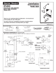
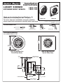
ROUGHING-IN DIMENSIONS
ALL CONNECTIONS 1/2" NPT
75mm
(3")
74mm D.
(2-15/16")
1660.130 Multifunction
Round Body Spray
1660.140 Multifunction
Square Body Spray
(75.6-82.6mm)
2-15/16" - 3-1/4"
26mm
(1")
12mm
(1/2")
15°
54mm D.
(2-1/8")
FINISHED WALL
57mm D.
(2-1/4")
HOLE SIZE
(63.6-70.6mm)
2-1/2" - 2-3/4"
35mm
(1-3/8")
1/2" NPT
1
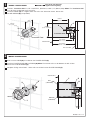
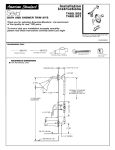
CAUTION
INSTALL SUPPLY PIPING
Turn off hot and cold water
supplies before beginning.
Provide a “Installation Hole” 2-1/8" - 2-3/8" DIA., (54-60mm) and 3-1/4", (83mm) deep. Note: The “Installation Hole”
must be clear to allow body spray clearance.
Install the ELBOW (1) on a support within the wall at the *dimension shown. Secure with
two M5 SCREWS (2) (not provided).
82.6mm
(3-1/4")
m
83m4")
/
(3-1
5
(2-1/8 4-60mm
" - 2-3
/8" DIA
.)
1
2
54-60mm
(2-1/8" - 2-3/8" DIA.)
1
{
“Installation Hole”
“Installation Hole”
2
FINISHED WALL
*63.6-70.6mm
(2-1/2" - 2-3/4")
*75.6-82.6mm
(2-15/16" - 3-1/4")
WALL SUPPORT
2
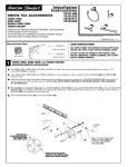
INSTALL PLASTER GUARD
Make sure the O-RING (3) is installed on the PLASTER GUARD (1).
Install the PLASTER GUARD (1) into ELBOW (2). Note: The finished wall must be between the Min. & Max.
lines on the PLASTER GUARD (1).
Complete all tiling and wall work. When walls are finished remove PLASTER GUARD (1).
FINISHED WALL
1
2
3
MAX.
(LINE MARK)
3
2
INSTALL
REMOVE
1
MINIMUM
(LINE MARK)
M 9 6 8 6 17 R ev. 1. 2
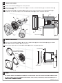
3
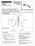
INSTALL BODY SPRAY
Remove the PLASTER GUARD (1) if not already removed.
Make sure the O-RING (2) and FLANGE GASKET (6) are installed on the BODY SPRAY (3). Thread BODY SPRAY (3)
into the ELBOW (4).
Tighten BODY SPRAY (3) using WRENCH (5) supplied until flush against finished wall and FLANGE GASKET (6) is
compressed. Turn on water supply and test installed BODY SPRAY (3) for leaks and proper operation.
2
4
6
4
2
3
3
1
6
5
FINISHED WALL
5
4
INSTALL ESCUTCHEON
Align ribs on back of ESCUTCHEON (1, 2), with slots in BODY SPRAY (3). Push ESCUTCHEON (1, 2) against BODY
SPRAY (3) until ESCUTCHEON (1, 2) snaps into place.
Turn on water supply and test installed BODY SPRAY (3) for leaks and proper operation.
FINISHED WALL
ALIGNMENT RIBS ON
BACK OF ESCUTCHEON
SLOTS
ALIGNMENT RIBS ON
BACK OF ESCUTCHEON
3
1
2
2
1
5
CARE:
DO: SIMPLY RINSE THE PRODUCT CLEAN WITH CLEAR WATER. DRY WITH A SOFT COTTON FLANNEL CLOTH.
DO NOT: DO NOT CLEAN THE PRODUCT WITH SOAPS, ACID, POLISH, ABRASIVES, HARSH CLEANERS, OR A
CLOTH WITH A COARSE SURFACE.
M 9 6 8 6 17 R ev. 1. 2