1
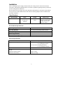
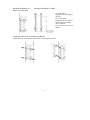
Broadband Indoor/Outdoor 150 W PowerShield CP150E48 Pole/Wall Mount Enclosure User Manual 990-1884C 06/2005 General Information The Indoor/Outdoor 150 W PowerShield provides power sourcing for broadband cable equipment. This unit may be mounted on a pole or wall. Safety-Save this Important Safety Information Read and follow all safety, installation, maintenance, and service instructions in this manual. Only trained service personnel should install and maintain the power supply enclosure. Changes and modifications to this unit not expressly approved by APC could void the warranty. Failure to observe these warnings may result in serious injury, death or damage to the equipment. This enclosure must remain locked at all times, except authorized service personnel are present. Do not work alone under hazardous conditions. Electrical Warnings Do not handle any metallic connector before the power has been disconnected. Servicing this equipment may require working with protective covers removed and utility power connected. Use extreme caution during these procedures. High current through conductive materials could cause severe burns. When grounding cannot be verified, disconnect the equipment from the utility power outlet before installing or connecting to other equipment. Reconnect the power cord only after all connections are made. Check that the power cord(s), plug(s), and sockets are in good condition. Replacement of fuses or other parts must be with identical types and ratings. Substitution of nonidentical parts may cause safety and fire hazards. Battery Warnings Always replace batteries with same or equivalent type recommended by the manufacturer. Danger of explosion if battery is incorrectly connected or replaced. Batteries present a risk of electrical shock and burns from high current in the event of a short-circuit. Observe proper safety precautions. Batteries must be recycled. Deliver the spent battery to a recycling facility or ship it to the supplier in the new battery packing material. Lifting Warnings Always use proper lifting techniques and equipment when handling units, modules, or batteries. 1 Installation Prior to installing the power supply enclosure utility line voltage must be routed to the enclosure. Local, state, federal and/or National Electric Code (NEC) regulations regarding location, permits and electrical wiring must be adhered to. Do not operate the power supply where the temperature and humidity are outside the specified limits. See Specifications in this manual. Position the enclosure ensuring adequate airflow around the unit for proper ventilation. Specifications Model Number CP150E48 Input 87-132 VAC 176-264 VAC 50/60 Hz Output 46-52 VDC 150 W Battery Type The use of an APC battery is recommended. Contact APC or your dealer for details. Environmental Specifications Operating Temperature -40º F to 131º F (-40º C to 55º C) Operating Humidity 0 to 100% noncondensing within enclosure Max Operating Elevation 10,000 ft (3,000 m) Max Storage Elevation 50,000 ft (15,000 m) Recommended Storage Temperature 41º F to 95º F (5º C to 35º C) Physical Specifications Characteristic Height X Width X Depth Weight Enclosure without a battery Enclosure with a battery Specification 17” x 17” x 10” excluding the bracket (12” including the bracket) (43 x 43x 26 cm excluding the bracket (31 cm including the bracket) 18 lbs (8.2 kg) 100 lbs (45.4 kg) 2 Unpack Inspect the unit upon receipt. Notify the carrier if there is damage. The packaging is recyclable; save it for reuse or dispose of it properly. The package contains: ➼ Enclosure with mounting bracket attached ➼ Battery cable assembly ➼ Product documentation. Install the Enclosure Installing the Mounting Bracket Prior to mounting the bracket on either pole or wall, remove the bracket from the enclosure by loosening the bolts that secure it to the enclosure. See diagram below. Mounting the Bracket on a Wood Pole 3 Mounting the Bracket on a Steel or Concrete Pole Mounting the Bracket on a Wall Use straps that are appropriate for the weight of this unit. Use screws that are appropriate for the weight of this unit and the mounting surface material. Refer to Specifications in this manual. Installing the Enclosure on the Mounting Bracket Tighten the bolts on the mounted bracket prior to installing the enclosure. 4 Connect Utility Power to the Enclosure Display panel located inside the enclosure. battery heater outlet Local, state, federal and/or National Electric Code (NEC) regulations regarding location, permits and electrical wiring must be adhered to. The customer supplied utility power cable may be routed through the side, top or bottom of the enclosure. Knockouts for this purpose are marked inside the enclosure. 1. Open the door of the enclosure. 2. Using the appropriate size utility power cable, wire the Euro block located on the display panel. See diagrams. Connect the ground wire prior to connecting any other wires. Install and Connect the Battery The use of an APC battery is recommended. Contact APC or your dealer for details. The battery terminals must be toward the front of the enclosure when the battery is installed. 5 Output Connections 7-Pin Communication Signals Connector Connect equipment to the UPS output connector receptacle via the seven-pin output connector (included), or use an APC custom data cable, (must be ordered separately). The PowerShield communication signals are isolated from its internal circuitry via open collector opto-coupled transistors. The connection labeled “Signal Return” is a common return point for all communication signals. In the typical application, the attached equipment digital ground connects to Signal Return, and pull-up resistors turn the open collector signals into logic levels. +Voltage output Voltage output Signal return. Low when operating from utility line. Open when operating from battery. Low when battery is charged. Open when battery fails the Self Test. Low when battery is present. Open when battery is missing. Low when battery is near full charge capacity. Open when operating from a battery with < 20% capacity. 16-Pin Terminal Board CPW029 Option The terminal board supplies uninterruptible power for up to eight sites grouped around the power supply. The terminal board output fuses automatically reset. Connect the positive W2 and negative W1 wires to the number one and two pins respectively on the 7-pin communication signal connector. See diagram. Output Grounding Either polarity of the output can be grounded to the ground stud located on the right side of the display panel. See diagram. Apply a non-oxidant paste to the ground stud prior to connecting the ground wire. 6 Status Indicators Status indicators are located on the display panel inside the enclosure. Green indicates the UPS is on utility power. Yellow indicates the UPS is on battery power. Green indicates DC output power is present. Red indicates that the battery is not connected or the battery needs to be replaced. Refer to the Battery Replacement section. Service, Contact and Warranty Information Service If the unit requires service do not return it to the dealer. Follow these steps: 1. If the problem persists, contact APC Customer Support through the APC Web site, www.apc.com. Note the model number of the unit, the serial number, and the date purchased. If you call APC Customer Support, a technician will ask you to describe the problem and try to solve it over the phone, if possible. If this is not possible, the technician will issue a Returned Material Authorization Number (RMA#). If the unit is under warranty, repairs are free. If not, there is a repair charge. Procedures for servicing or returning products may vary internationally. Refer to the APC Web site, www.apc.com. 2. Pack the UPS in its original packaging. Pack the unit properly to avoid damage in transit. Never use Styrofoam beads for packaging. Damage sustained in transit is not covered under warranty. Do not ship with the battery installed inside the enclosure. Ship the battery and the enclosure separately. How to Contact APC Refer to the APC Web site, www.apc.com. 7 Limited Warranty American Power Conversion (APC) warrants its products to be free from defects in materials and workmanship for a period of two years from the date of purchase. Its obligation under this warranty is limited to repairing or replacing, at its own sole option, any such defective products. To obtain service under warranty you must obtain a Returned Material Authorization (RMA) number from customer support. Products must be returned with transportation charges prepaid and must be accompanied by a brief description of the problem encountered and proof of date and place of purchase. This warranty does not apply to equipment that has been damaged by accident, negligence, or misapplication or has been altered or modified in any way. This warranty applies only to the original purchaser who must have properly registered the product within 10 days of purchase. EXCEPT AS PROVIDED HEREIN, AMERICAN POWER CONVERSION MAKES NO WARRANTIES, EXPRESSED OR IMPLIED, INCLUDING WARRANTIES OF MERCHANTABILITY AND FITNESS FOR A PARTICULAR PURPOSE. Some states do not permit limitation or exclusion of implied warranties; therefore, the aforesaid limitation(s) or exclusion(s) may not apply to the purchaser. EXCEPT AS PROVIDED ABOVE, IN NO EVENT WILL APC BE LIABLE FOR DIRECT, INDIRECT, SPECIAL, INCIDENTAL, OR CONSEQUENTIAL DAMAGES ARISING OUT OF THE USE OF THIS PRODUCT, EVEN IF ADVISED OF THE POSSIBILITY OF SUCH DAMAGE. Specifically, APC is not liable for any costs, such as lost profits or revenue, loss of equipment, loss of use of equipment, loss of software, loss of data, costs of substitutes, claims by third parties, or otherwise. Regulatory Approval Entire contents copyright 2005 by American Power Conversion Corporation. All rights reserved. Reproduction in whole or in part without permission is prohibited. APC, the APC logo, and PowerShield are registered trademarks of American Power Conversion Corporation. All other trademarks are the property of their respective owners. 8