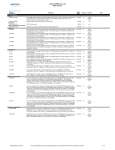
1
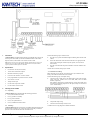
KT-PC4204 4 Relay Output and Power Supply 1. Introduction Perform the following steps to mount the unit: The KT-PC4204 is an output module with four programmable relays and can be used to repower the Combus (see KT-300 installation manual in the Combus Repower Section). This module is also used for elevator control. 1. Press the five (5) plastic standoffs through the mounting holes at back of the cabinet, 2. Secure the cabinet to the wall in the desired location. Use appropriate wall anchors when securing the cabinet to drywall, plaster, concrete, brick or other surfaces, 3. Press the circuit board into the plastic standoffs to secure the module to the cabinet. Note: Do not use any power supply other than the KT-PC4204 to repower the Combus. If a power supply other than the KT-PC4204 is used, the Combus repower function will not operate as intended. 2. 3. Specifications Once the unit is mounted, wiring may be started. • Current Draw: 30 mA (from Combus) • 16VAC/40VA transformer required 3.3. Installation and Wiring • Maximum 7Ah battery required • Connects to the controller via 4-wire Combus Before beginning to wire the unit, ensure that all power (AC transformer and battery) is disconnected from the KT-300 controller. • Four programmable relay contacts rated 2A, 30VDC • AUX current: 1.0A max. • Tamper contact input • Can be used to repower the combus • Can be used for elevator control Perform the following steps to complete wiring: 1. Connect the four Combus wires to the KT-PC4204. Connect the red, black, yellow and green Combus wires to the RED, BLK, YEL and GRN terminals, respectively. If the module is being used for Combus Repower, connect the Combus wires according to the following diagram. For this option, Jumper J1 must also be set for “Combus Relay.” Installing the KT-PC4204 3.1. Unpacking The KT-PC4204 package should include the following parts/items: • One (1) KT-PC4204 circuit board • One (1) ground wire assembly • Five (5) plastic standoffs • One (1) 5A replacement fuse 2. Complete all output wiring, • One (1) installation instructions sheet 3. Connect the external tamper switch, if used. 3.2. Consult the above wiring diagrams for further information. Mounting The KT-PC4204 should be located inside a compatible cabinet (Kantech part no. KT-4051CAB), mounted in a dry and secure location. Preferably, it should be placed at a convenient distance from the connected devices. Kantech Systems Tel.: 1 (450) 444 2030 • Toll Free: 1 888 222-1560 • Fax: 1 (450) 444 2029 • Internet: www.kantech.com Copyright 2004 Kantech Systems. All rights reserved • Specifications may change without notice. DN1246-0404 KT-PC4204 4 Relay Output and Power Supply 3.4. Applying Power 3. After all wiring is completed, apply power to the KT-300. Connect the battery leads to the battery, then connect the AC transformer. Then, connect power to the KT-PC4204: the battery leads followed by the AC transformer. A serial number should be displayed on the screen, in the same window where is the serial number appears, you should see the type of module and on which controller it is connected, 4. From the software, select the functionality of the module and enter the serial number in the appropriate field (see your software reference manual under controller definition -- Assigning modules for more details), 5. If the module is used in “repower” mode, assign an “all valid” schedule to relay 1 and assign the module’s functionality to “relay 1 to 4” in your software. Note: Do not connect the power until all wiring is complete. 4. Assigning the KT-PC4204 module Once all wiring is complete, the module must be assigned to the system. To assign the module, perform the following steps: 1. Establish communication between the PC and the controller, 2. Remove the tamper switch wire (or only the wire if tamper switch is not used), Note: Don’t forget to reconnect the tamper switch (or the wire, if there is no tamper switch). Note: If the module is uses as a “repower” module, ensure that Jumper J1 is set to “Combus Relay” position. Terminal Connections Module no.: ______________________________________________________________________________________ Date of installation: _______________________________________________________________________________ KT-300 Name: ____________________________________________________________________________________ KT-300 SITE NAME: _______________________________________________________________________________ KT-300 Serial Number: _____________________________________________________________________________ AUX: ___________________________________________________________________________________________ COMBUS (FROM):_________________________________________________________________________________ COMBUS (TO): ___________________________________________________________________________________ Repower: YES: (if yes, assign an “All valid” schedule to Relay 1) NO: RLY1: Normally open (NO): ________________________________________________________________________ Normally closed (NC): _______________________________________________________________________ RLY2: Normally open (NO): ________________________________________________________________________ Normally closed (NC): _______________________________________________________________________ RLY3: Normally open (NO): ________________________________________________________________________ Normally closed (NC): _______________________________________________________________________ RLY4: Normally open (NO): ________________________________________________________________________ Normally closed (NC): _______________________________________________________________________ FCC & IC COMPLIANCE STATEMENT CAUTION: Changes or modifications not expressly approved by Kantech Systems Inc. could void your authority to use this equipment. This equipment generates and uses radio frequency energy and if not installed and used properly, in strict accordance with the manufacturer’s instructions, may cause interference to radio and television reception. It has been type tested and found to comply with the limits for Class B device in accordance with the specifications in Subpart “B” of Part 15 of FCC Rules, which are designed to provide reasonable protection against such interference in any residential installation. However, there is no guarantee that interference will not occur in a particular installation. If this equipment does cause interference to television or radio reception, which can be determined by turning the equipment off and on, the user is encouraged to try to correct the interference by one or more of the following measures: • Re-orient the receiving antenna • Relocate the alarm control with respect to the receiver • Move the alarm control away from the receiver • Connect the alarm control into a different outlet so that alarm control and receiver are on different circuits. If necessary, the user should consult the dealer or an experienced radio/television technician for additional suggestions. The user may find the following booklet prepared by the FCC helpful: “How to Identify and Resolve Radio/Television Interference Problems”. This booklet is available from the U.S. Government Printing Office, Washington, D.C. 20402, Stock # 004-000-00345-4. This device complies with Part 15 of the FCC rules. Operation is subject to the following two conditions: (1) this device may not cause harmful interference, and (2) this device must accept any interference received including interference that may cause undesired operation. This class B digital apparatus meets all requirements of the Canadian Interference Causing Equipment Regulations. The KT-300 is also compliant with EN55022: 1994, amendment 1: 1995, Class B. Kantech Systems Tel.: 1 (450) 444 2030 • Toll Free: 1 888 222-1560 • Fax: 1 (450) 444 2029 • Internet: www.kantech.com Copyright 2004 Kantech Systems. All rights reserved • Specifications may change without notice. DN1246-0404