1
ALTEC
POWER E Mia ==)
INTRODUCTION
The ALTEC LANSING Model 1270 Power
Amplifier provides continuous high power
demand where uninterrupted operation is
requisite. Designed to protect itself and the
acoustic elements it drives, the Model 1270
represents 800 + watts of controlled power.
Two channels may be operated independ-
ently, in parallel or in bridged configuration
to deliver up to 400 watts per channel at
less than 0.05% THD from 20 Hz to 20 kHz.
Peak Error Computer
The amplifier is provided with a peak/error
computer that compares channel input and
output signals and detects any output
errors. Detection of any peak/error causes
the appropriate peak/error indicator to illu-
minate. Output anomalies detected include
excessive voltage, excessive current (load),
excessive slew rate, and any other signifi-
cant difference between the channel input
and output signal.
Amplifier Protection
The amplifier output is continuously mon-
itored to guard against excessive current
drain. An instantaneous VI limiter restricts
output to 400 VA +45* phase shift. The
amplifier is additionally protected against
excessive operating temperature; logic cir-
cuitry automatically overrides low-speed
fan operation and locks to the high fan
speed mode. If operating temperature
remains excessive, the load is discon-
nected by a relay and the protection indica-
tor illuminates. When temperature falls to
safe operating conditions, the amplifier
automatically resumes operation.
LANSING |
ALTEC
LANSING’
1270 POWER AMPLIFIER
OPERATING
INSTRUCTIONS
CAUTION:
IMPORTANT:
qualifié.
No user-serviceable parts inside. Hazardous voltage may be en-
countered within the chassis. Installation and Service information
within this document is for use only by ALTEC sound contractors, factory authorized
warranty stations and qualified service personnel.
Il est enjoint à l'utilisateur de ne pas réparer lui-même les pièces
internes de l'appareil, des courants à haute tension pouvant pas-
ser à l'intérieur du châssis. Les renseignements inclus dans ce document sont destinés
uniquement à l'usage des installateurs agréés des systèmes acoustiques ALTEC, des
centres de réparation sous garantie autorisés, ainsi que du personnel d'entretien
Load Protection
The load is protected from transients dur-
ing startup and shutdown of the amplifier.
During startup, the load remains discon-
nected through a relay during a three-
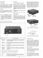
FRONT PANEL CONTROLS AND FEATURES
second delay period. During shutdown or
loss of power, the load is instantaneously
disconnected by the relay. The load is simi-
larly protected against amplifier failure,
such as dc voltage at the output.
Item Name
Function/Description
1 Peak/Error
Indicators
2 Protection
Indicator
3 |POWER
Indicator
4 | POWER Switch
5 | CHANNEL
Volume
Controls
increase gain.
Illuminate when excessive voltage, current or slew rate ap-
pears at the output terminals.
Illuminates when protection circuitry operates to prevent dam-
age to the amplifier or load.
Illuminated when primary ac power is applied to the amplifier.
Applies primary ac power to the amplifier.
Adjust gain of LEFT and RIGHT channels. Rotate clockwise to
1515 S. Manchester Ave., Anaheim, Calif. 92803
Specifications and components subject to change without
notice. Overall performance will be maintained or improved.
42-02-045589-01
LITHO IN U.S.A. 681-1M
INSTALLATION
Rack Mounting
The 1270 may be installed in a standard
19-inch equipment rack, or in the 42526
Shelf Mount Cover Accessory for shelf use.
Vertical space required is 51”. Rack instal-
lation is accomplished by using the appro-
priate four mounting screws supplied.
Ventilation
The 1270 must be adequately ventilated to
prevent excessive temperature rise. Max-
imum rated ambient operating temperature
is 55°C (131°F).
CAUTION
Do not block the side ventilation
aperatures on either side of the main
frame. Allow at least 2” on each side
of the main frame to assure adequate
ventilation. Do not operate within a
completely closed, unventilated
housing.
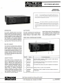
REAR PANEL CONTROLS AND FEATURES
ELECTRICAL
120 Volt, 50/60 Hz Power Connections
Equipment supplied for domestic use is
provided with the power transformer
primary strapped for 120 volts. Specified
voltage rating is located on the chassis,
adjacent to the power cord. Verify that line
voltage is in accordance with specified volt-
age before connecting the 1270 to ac line
power.
100V, 200V, 220V, 240V, 50/60 Hz Power
Connections
Refer to Authorized Altec Service
Representative.
Input Connections
Unbalanced input connections to the
INPUT jacks are made with shielded single-
conductor cables terminated with standard
'4-inch phone jacks. In preparing the cable,
the conductor is soldered to the tip of the
jack, and the shield is soldered to the
sleeve.
fa A hd
ET = LTE 23]
MADE 7 EA
Item Name
Function/Description
1 OUTPUT
Terminals
2 {INPUT
Receptacies
(r) receptacles.
3 ILINE
Receptacles
receptacles.
4 |BRIDGE/
NORMAL
Switch
into 8 ohms.
5 | COM Terminal
6 |GND Terminal
7 | FAN Switch
8 Fuse
Connect left (L) and right (R) channels to corresponding speak-
ers. Two pair of standard GR jacks have red (+) and black (—)
polarity designations.
Accept cables from high impedance (nominal 15,000 ohms)
sources. Use standard ring and sleeve plug for left (L) and right
Accept cables to connect other Altec Amplifiers in parallel.
Use standard ring and sleeve plug for left (L) and right (R)
Connects internal circuitry for independent or mono operation
(NORMAL) into a 4-ohm load, of bridge operation (BRIDGE)
Provides connection to circuit common.
Provides connection to chassis ground.
Selects low (1) or high (2) fan speed.
Protects amplifier from excessive current drain. Replace only
with same type 10-ampere fuse, Refer to qualified service per-
sonnel if fuse blows repeatedly.
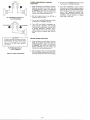
Balanced input connections are made with
the optional 1270TM Dual Balanced Trans-
former Input Module. Plug the 1270TM into
the INPUT receptacles of the 1270 and
secure the retaining screw. See Figure 1.
Cables terminated with XLR3-type connec-
tors are used to make input connections to
the 1270 TM module; wiring for the XLR3-
type connector is shown in Figure 2.
SECURING
SCREW
TRANSFORMER
MODULE
INPUT
RECEPTACLES
MODULE JACKS
CHANNEL INPUT
RECEPTACLES
1b. Module Installed
Figure 1. Installation of 1270TM Module
WHT i, mT
XLR3
PLUG
Figure 2. Wiring for XLR3-type Connector
Line Qut Connections
Connections to LINE OUT receptacles are
made with shielded single-conductor
cables terminated with standard '-inch
phone jacks. When channels are operated
independently (stereo operation) a cable
must connect each channel of each addi-
tional 1270 amplifier connected in multiple.
When channels are operated in the bridge
mode, only the left channel of each addi-
tional 1270 requires a connecting cable.
Output Connections
Output connections are made at the L and
R OUTPUT terminals. Figure 3 illustrates
connections for independent (stereo) opera-
tion and for bridged operation.
GND and COM Connections
The GND (chassis ground) and COM (elec-
trical common) terminals are used to cor-
rect unsatisfactory grounding conditions
and for establishing desired grounding
configurations.
cu
3a. Independent Operation of
L and R Channels
OUTPUT
HE
NOT CONNECTED
Te
80
NOT CONNECTED
CAUTION ——
Bridged operaton provides a true bal-
anced output. Do not connect either
side of the loudspeaker line to audio
common or to any other “ground”
connection.
3b. Bridge Operation of
L and R Channels
Figure 3. Output Connections
STEREO (INDEPENDENT CHANNEL)
OPERATION
1.
>
After installation and hookup of connec-
tions as in Figure 3A, check that the
BRIDGE/NORMAL switch is positioned
at NORMAL, and that the LEFT and
RIGHT CHANNEL volume controls are
turned fully counterclockwise. («).
Set input signal level to the 1270 at a
nominal value of 0.775V.
Turn on ac line POWER switch and note
illumination of POWER indicator.
Turn LEFT and RIGHT CHANNEL vol-
ume controls clockwise until desired
output power is obtained. If either LEFT
or RIGHT peak/error indicator illumi-
nates, reduce output level with channel
volume control or reduce input level to
1270.
BRIDGE (MONO) OPERATION
1.
After installation and hookup of connec-
tions as in Figure 3B, check that the
BRIDGE/NORMAL switch is positioned
at BRIDGE, and that the LEFT and
RIGHT CHANNEL volume controls are
turned fully counterclockwise (co).
Set input signal level to the left (L) INPUT
of the 1270 at a nominal value of 0.775V.
(The right (R) INPUT is left unconnected.)
3.
4.
Turn on ac line POWER switch and note
illumination of POWER indicator.
Turn LEFT CHANNEL volume control
clockwise until desired output power is
obtained. Be sure to leave RIGHT CHAN-
NEL volume control fully counterclock-
wise. If LEFT peak/error indicator illu-
minates, reduce output level with LEFT
CHANNEL volume control, or reduce
input level to the 1270.