1
Management
Software
Layer 2-4 Gigabit
Ethernet EcoSwitches
AT-9000/28
AT-9000/28SP
AT-9000/52
◆
Web Browser
User’s Guide
AlliedWare Plus Version 2.1.2
613-001443 Rev A
Copyright
Copyright © 2010, Allied Telesis, Inc.
All rights reserved.
This product includes software licensed under the BSD License. As such, the following language applies for those portions of
the software licensed under the BSD License:
Redistribution and use in source and binary forms, with or without modification, are permitted provided that the following
conditions are met:
* Redistributions of source code must retain the above copyright notice, this list of conditions and the following disclaimer.
* Redistributions in binary form must reproduce the above copyright notice, this list of conditions and the following
disclaimer in the documentation and/or other materials provided with the distribution.
* Neither the name of Allied Telesis, Inc. nor the names of the respective companies above may be used to endorse or promote
products derived from this software without specific prior written permission.
THIS SOFTWARE IS PROVIDED BY THE COPYRIGHT HOLDERS AND CONTRIBUTORS "AS IS" AND ANY
EXPRESS OR IMPLIED WARRANTIES, INCLUDING, BUT NOT LIMITED TO, THE IMPLIED WARRANTIES OF
MERCHANTABILITY AND FITNESS FOR A PARTICULAR PURPOSE ARE DISCLAIMED. IN NO EVENT SHALL
THE COPYRIGHT HOLDER OR CONTRIBUTORS BE LIABLE FOR ANY DIRECT, INDIRECT, INCIDENTAL,
SPECIAL, EXEMPLARY, OR CONSEQUENTIAL DAMAGES (INCLUDING, BUT NOT LIMITED TO,
PROCUREMENT OF SUBSTITUTE GOODS OR SERVICES; LOSS OF USE, DATA, OR PROFITS; OR BUSINESS
INTERRUPTION) HOWEVER CAUSED AND ON ANY THEORY OF LIABILITY, WHETHER IN CONTRACT,
STRICT LIABILITY, OR TORT (INCLUDING NEGLIGENCE OR OTHERWISE) ARISING IN ANY WAY OUT OF THE
USE OF THIS SOFTWARE, EVEN IF ADVISED OF THE POSSIBILITY OF SUCH DAMAGE.
Copyright 1989, 1991, 1992 by Carnegie Mellon University. Derivative Work - 1996, 1998-2000. Copyright 1996, 1998-2000
by The Regents of the University of California - All rights reserved. Copyright (c) 2001-2003 by Networks Associates
Technology, Inc. - All rights reserved. Copyright (c) 2001-2003 by Cambridge Broadband Ltd. - All rights reserved. Copyright
(c) 2003 by Sun Microsystems, Inc. - All rights reserved. Copyright (c) 2003-2005 by Sparta, Inc. - All rights reserved.
Copyright (c) 2004 by Cisco, Inc. and Information Network Center of Beijing University of Posts and Telecommunications. All rights reserved. Copyright (c) 2003 by Fabasoft R&D Software GmbH & Co KG - All rights reserved. Copyright (c) 20042006 by Internet Systems Consortium, Inc. ("ISC") - All rights reserved. Copyright (c) 1995-2003 by Internet Software
Consortium - All rights reserved. Copyright (c) 1992-2003 by David Mills - All rights reserved. Copyright (c) 1995 by Tatu
Ylonen <[email protected]>, Espoo, Finland - All rights reserved. Copyright (c) 1998 by CORE SDI S.A., Buenos Aires,
Argentina - All rights reserved. Copyright 1995, 1996 by David Mazieres - All rights reserved. Copyright 1983, 1990, 1992,
1993, 1995 by The Regents of the University of California - All rights reserved. Copyright (c) 1995 Patrick Powell - All rights
reserved. Copyright (c) 1998-2005 The OpenSSL Project - All rights reserved. Copyright (C) 1995-1998 Eric Young
([email protected]) - All rights reserved. Copyright (c) 2008, Henry Kwok - All rights reserved. Copyright (c) 1995, 1998,
1999, 2000, 2001 by Jef Poskanzer <[email protected]>. - All rights reserved.
Some components of the SSH software are provided under a standard 2-term BSD license with the following names as
copyright holders: Markus Friedl, Theo de Raadt, Niels Provos, Dug Song, Aaron Campbell, Damien Miller, Kevin Steves,
Daniel Kouril, Wesley Griffin, Per Allansson, Nils Nordman, and Simon Wilkinson,
Portable OpenSSH includes code from the following copyright holders, also under the 2-term BSD license: Ben Lindstrom,
Tim Rice, Andre Lucas, Chris Adams, Corinna Vinschen, Cray Inc., Denis Parker, Gert Doering, Jakob Schlyter, Jason
Downs, Juha Yrjola, Michael Stone, Network Associates, Solar Designer, Todd C. Miller, Wayne Schroeder, William Jones,
Darren Tucker, Sun Microsystems, The SCO Group.
Some Portable OpenSSH code is licensed under a 3-term BSD style license to the following copyright holders: Todd C. Miller,
Theo de Raadt, Damien Miller, Eric P. Allman, The Regents of the University of California, and Constantin S. Svintsoff. Some
Portable OpenSSH code is licensed under an ISC-style license to the following copyright holders: Internet Software
Consortium, Todd C. Miller, Reyk Floeter, and Chad Mynhier. Some Portable OpenSSH code is licensed under a MIT-style
license to the following copyright holder: Free Software Foundation, Inc.
This product also includes software licensed under the GNU General Public License available from:
http://www.gnu.org/licenses/gpl2.html
Allied Telesis is committed to meeting the requirements of the open source licenses including the GNU General Public
License (GPL) and will make all required source code available.
If you would like a copy of the GPL source code contained in this product, please send us a request by registered mail
including a check for US$15 to cover production and shipping costs, and a CD with the GPL code will be mailed to you.
GPL Code Request
Allied Telesis, Inc.
3200 North First Street
San Jose, California 95134
No part of this publication may be reproduced without prior written permission from Allied Telesis, Inc.
Allied Telesis, AlliedWare Plus, and the Allied Telesis logo are trademarks of Allied Telesis, Incorporated. Microsoft and
Internet Explorer are registered trademarks of Microsoft Corporation. All other product names, company names, logos or
other designations mentioned herein are trademarks or registered trademarks of their respective owners.
Allied Telesis, Inc. reserves the right to make changes in specifications and other information contained in this document
without prior written notice. The information provided herein is subject to change without notice. In no event shall Allied
Telesis, Inc. be liable for any incidental, special, indirect, or consequential damages whatsoever, including but not limited
to lost profits, arising out of or related to this manual or the information contained herein, even if Allied Telesis, Inc. has
been advised of, known, or should have known, the possibility of such damages.
Contents
Preface ............................................................................................................................................................ 11
Document Conventions .................................................................................................................................... 12
Downloading Management Software and Web-based Guides......................................................................... 13
Contacting Allied Telesis .................................................................................................................................. 14
Online Support ........................................................................................................................................... 14
Email and Telephone Support.................................................................................................................... 14
Returning Products .................................................................................................................................... 14
Sales or Corporate Information .................................................................................................................. 14
Management Software Updates................................................................................................................. 14
Chapter 1: AlliedWare Plus™ Version 2.1.2 Web Browser Interface ........................................................ 15
Management Sessions ..................................................................................................................................... 16
Web Manager Accounts ................................................................................................................................... 17
Chapter 2: Starting a Management Session ............................................................................................... 19
Starting a Web Management Session .............................................................................................................. 20
Selecting items from a Web Page .................................................................................................................... 26
What to Configure First..................................................................................................................................... 27
Assigning a Name to the Switch ................................................................................................................ 27
Adding a Management IP Address ............................................................................................................ 27
Setting System Time .................................................................................................................................. 27
Saving Your Changes....................................................................................................................................... 28
Ending a Web Management Session ............................................................................................................... 29
Chapter 3: Basic Switch Parameters ........................................................................................................... 31
Setting the System Date and Time................................................................................................................... 32
Setting System Time Manually................................................................................................................... 33
Setting An SNTP or NTP Server ................................................................................................................ 35
Setting a Telnet or SSH Server ........................................................................................................................ 38
Setting a Remote Log Server ........................................................................................................................... 40
Setting the Switch Information.......................................................................................................................... 41
Setting the Configuration File ........................................................................................................................... 43
Displaying and Setting the Active Configuration File ................................................................................. 43
Uploading a Configuration File................................................................................................................... 44
Managing User Accounts ................................................................................................................................. 45
Adding a User ............................................................................................................................................ 45
Changing a User Password ....................................................................................................................... 46
Changing the User Privilege ...................................................................................................................... 48
Deleting a User .......................................................................................................................................... 49
Rebooting a Switch........................................................................................................................................... 50
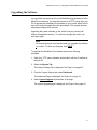
Upgrading the Software.................................................................................................................................... 51
Returning the AlliedWare Plus Management Software to the Factory Default Values ..................................... 53
Displaying System Information ......................................................................................................................... 54
Chapter 4: Setting Port Parameters ............................................................................................................. 57
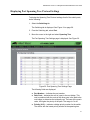
Displaying the Port Parameters........................................................................................................................ 58
Changing the Port Settings............................................................................................................................... 62
5
Contents
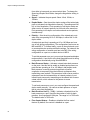
Displaying the Storm Control Settings .............................................................................................................. 66
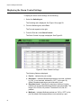
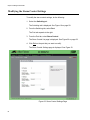
Modifying the Storm Control Settings ............................................................................................................... 68
Chapter 5: Setting Port Statistics ................................................................................................................. 71
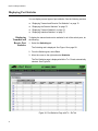
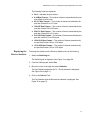
Displaying Port Statistics .................................................................................................................................. 72
Displaying Transmit and Receive Port Statistics ........................................................................................ 72
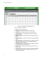
Displaying the Receive Statistics................................................................................................................ 73
Displaying Transmit Statistics..................................................................................................................... 75
Displaying Interface Statistics..................................................................................................................... 77
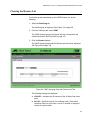
Clearing Port Statistics...................................................................................................................................... 79
Chapter 6: Setting Port Mirroring ................................................................................................................. 81
Overview ........................................................................................................................................................... 82
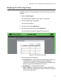
Displaying Port Mirroring Settings..................................................................................................................... 83
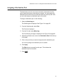
Assigning a Destination Port ............................................................................................................................. 85
Assigning Port Mirroring Values........................................................................................................................ 86
Chapter 7: Setting the Port Spanning Tree Protocol .................................................................................. 89
Overview ........................................................................................................................................................... 90
Displaying Port Spanning Tree Protocol Settings ............................................................................................. 91
Modifying Port Spanning Tree Protocol Settings ..............................................................................................93
Chapter 8: Setting the MAC Address ...........................................................................................................95
Displaying the MAC Address ............................................................................................................................ 96
Displaying the Unicast MAC Addresses ..................................................................................................... 96
Displaying Multicast Addresses.................................................................................................................. 97
Assigning a MAC Address ................................................................................................................................ 99
Assigning an Unicast Address.................................................................................................................... 99
Assigning a Multicast Address..................................................................................................................100
Deleting a MAC Address.................................................................................................................................102
Deleting a Unicast Address ......................................................................................................................102
Deleting a Multicast Address ....................................................................................................................102
Chapter 9: Setting LACP .............................................................................................................................105
Overview .........................................................................................................................................................106
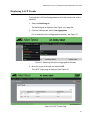
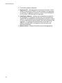
Displaying LACP Trunks .................................................................................................................................107
Adding an LACP Trunk ...................................................................................................................................109
Modifying an LACP Trunk ...............................................................................................................................111
Deleting an LACP Trunk .................................................................................................................................113
Chapter 10: Setting Static Port Trunks ......................................................................................................115
Overview .........................................................................................................................................................116
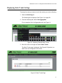
Displaying Static Trunk Settings .....................................................................................................................117
Adding Static Trunks .......................................................................................................................................119
Modifying the Static Trunk Settings ................................................................................................................122
Deleting Static Trunks .....................................................................................................................................125
Chapter 11: Setting Port-based and Tagged VLANs ................................................................................127
Overview .........................................................................................................................................................128
Port-based VLANs....................................................................................................................................128
Tagged VLANs .........................................................................................................................................128
Tagged and Untagged Ports ....................................................................................................................129
Displaying VLANs ...........................................................................................................................................130
Adding an VLAN .............................................................................................................................................132
Modifying VLANs ............................................................................................................................................134
Deleting VLANs...............................................................................................................................................136
6
AlliedWare Plus Version 2.1.2 Management Software Web Browser User’s Guide
Chapter 12: Setting Switch Spanning Tree Protocols ............................................................................. 137
Overview......................................................................................................................................................... 138
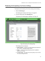
Displaying Switch Spanning Tree Protocol Settings....................................................................................... 139
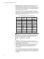
Modifying Switch Spanning Tree Protocol Settings........................................................................................ 142
Chapter 13: Setting Internet Group Management Protocol (IGMP) Snooping ....................................... 145
Overview......................................................................................................................................................... 146
Displaying and Modifying IGMP Snooping Configuration............................................................................... 147
Clearing the Routers List ................................................................................................................................ 149
Disabling IGMP Snooping .............................................................................................................................. 151
Displaying the Routers List............................................................................................................................. 152
Displaying the Hosts List ................................................................................................................................ 153
Chapter 14: Setting MAC Address-based Port Security .......................................................................... 155
Overview......................................................................................................................................................... 156
Static Versus Dynamic Addresses ........................................................................................................... 156
Intrusion Actions....................................................................................................................................... 156
Guidelines ................................................................................................................................................ 157
Displaying the MAC Address-based Port Security Settings ........................................................................... 158
Modifying the MAC Address-based Port Security Settings ............................................................................ 160
Disabling MAC Address-based Port Security Settings ................................................................................... 162
Chapter 15: Setting RADIUS and TACACS+ Clients ................................................................................ 163
Overview......................................................................................................................................................... 164
Remote Manager Accounts...................................................................................................................... 164
Configuring TACACS+ and RADIUS ....................................................................................................... 165
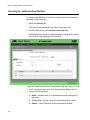
Selecting the Authentication Method .............................................................................................................. 166
Configuring the Authentication Server............................................................................................................ 168
Configuring a TACACS+ Server .............................................................................................................. 168
Configuring a RADIUS Server.................................................................................................................. 170
Deleting an Authentication Server .................................................................................................................. 173
Chapter 16: Setting 802.1x Port-based Network Access ......................................................................... 175
Overview......................................................................................................................................................... 176
Enabling 802.1x Port-based Authentication on the Switch............................................................................. 177
Configuring 802.1x Port-based Authentication ............................................................................................... 178
Displaying the 802.1x Authentication Port Settings........................................................................................ 183
Disabling 802.1x Port-based Authentication on the Switch ............................................................................ 184
Disabling 802.1x Port-based Authentication on a Port ................................................................................... 185
Chapter 17: Setting IPv4 and IPv6 Management ...................................................................................... 187
Overview......................................................................................................................................................... 188
IP Management Guidelines...................................................................................................................... 189
Assigning an IPv4 Address............................................................................................................................. 190
Assigning a Static IPv4 Address .............................................................................................................. 190
Assigning an DHCP IPv4 Address ........................................................................................................... 192
Assigning an IPv6 Address............................................................................................................................. 194
Displaying IP Addresses................................................................................................................................. 196
Deleting IP Addresses .................................................................................................................................... 197
Deleting an IPv4 Static Address............................................................................................................... 197
Deleting an DHCP IPv4 Address ............................................................................................................. 197
Deleting an IPv6 Address......................................................................................................................... 198
Chapter 18: Setting LLDP and LLDP-MED ................................................................................................ 199
Overview......................................................................................................................................................... 200
Setting LLDP Locations .................................................................................................................................. 201
Creating a Civic Location ......................................................................................................................... 201
Creating a Coordinate Location ............................................................................................................... 205
7
Contents
Creating an ELIN Location .......................................................................................................................207
Configuring LLDP and LLDP-MED .................................................................................................................210
Setting the Basic LLDP Configuration ......................................................................................................210
Setting LLDP Port Assignments ...............................................................................................................212
Assigning Port Locations ..........................................................................................................................214
Enabling LLDP TLV ..................................................................................................................................216
Enabling LLDP- MED TLV........................................................................................................................220
Displaying LLDP Neighbor Information ...........................................................................................................223
Displaying LLDP Statistics ..............................................................................................................................225
Displaying LLDP Locations .............................................................................................................................228
Displaying Civic Locations........................................................................................................................228
Displaying Coordinate Locations ..............................................................................................................229
Displaying ELIN Locations........................................................................................................................230
Displaying LLDP and LLDP-MED Settings .....................................................................................................232
Displaying the Basic LLDP Configuration.................................................................................................232
Displaying LLDP Port Assignments..........................................................................................................233
Displaying Port Locations .........................................................................................................................234
Displaying LLDP TLV ...............................................................................................................................234
Displaying LLDP-MED TLV ......................................................................................................................236
Disabling LLDP on the Switch.........................................................................................................................238
Chapter 19: Setting sFlow ...........................................................................................................................239
Overview .........................................................................................................................................................240
Ingress Packet Samples...........................................................................................................................240
Packet Counters .......................................................................................................................................240
sFlow Collectors .......................................................................................................................................241
Guidelines.................................................................................................................................................241
Enabling sFlow on the Switch .........................................................................................................................242
Configuring sFlow on a Port............................................................................................................................243
Specifying an sFlow Collector .........................................................................................................................245
Displaying the sFlow Settings .........................................................................................................................247
8
Figures
Figure 1: Login Menu............................................................................................................................................................20
Figure 2: Displaying the IP address......................................................................................................................................21
Figure 3: Login Page ............................................................................................................................................................22
Figure 4: Dashboard Page ...................................................................................................................................................23
Figure 5: System Contact Information Page.........................................................................................................................28
Figure 6: System Settings Tab .............................................................................................................................................33
Figure 7: System Time Settings Page ..................................................................................................................................34
Figure 8: Calendar Page ......................................................................................................................................................35
Figure 9: System Time Settings Page with Network Time Settings Tab ..............................................................................36
Figure 10: System Services Page ........................................................................................................................................39
Figure 11: System Contact Information Page.......................................................................................................................41
Figure 12: Configuration Files Page .....................................................................................................................................43
Figure 13: File Upload Page .................................................................................................................................................44
Figure 14: User Management Page......................................................................................................................................45
Figure 15: User Management Page with Change Password Tab.........................................................................................47
Figure 16: User Management Page with Change Privilege Tab...........................................................................................48
Figure 17: User Management Page with Delete User Tab ...................................................................................................49
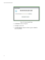
Figure 18: System Upgrade Page ........................................................................................................................................52
Figure 19: Switching Tab with Port Tab................................................................................................................................58
Figure 20: Port Configuration Page ......................................................................................................................................59
Figure 21: Port Configuration Modify Page...........................................................................................................................63
Figure 22: Storm Control List Page ......................................................................................................................................66
Figure 23: Storm Control Settings Page ...............................................................................................................................68
Figure 24: Port Statistics Page with Tx + Rx Tab .................................................................................................................72
Figure 25: Port Statistics with the Receive Tab ....................................................................................................................74
Figure 26: Port Statistics with the Transmit Tab ...................................................................................................................76
Figure 27: Port Statistics Page with Interface Tab................................................................................................................77
Figure 28: Port Mirroring List Page.......................................................................................................................................83
Figure 29: Modify Port Mirroring Page..................................................................................................................................86
Figure 30: Port Spanning Tree Settings Page ......................................................................................................................91
Figure 31: Modify Port Spanning Tree Settings Page ..........................................................................................................93
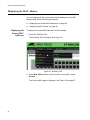
Figure 32: Switching Tab ......................................................................................................................................................96
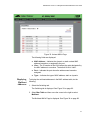
Figure 33: Unicast MACs Page ............................................................................................................................................97
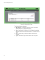
Figure 34: Multicast MACs Page ..........................................................................................................................................98
Figure 35: Unicast MAC Page ..............................................................................................................................................99
Figure 36: Multicast Mac Address Page .............................................................................................................................100
Figure 37: Switching Tab with Link Aggregation Selected..................................................................................................107
Figure 38: LACP Trunks Page............................................................................................................................................107
Figure 39: Add LACP Trunk Page ......................................................................................................................................109
Figure 40: Modify LACP Trunk Page ..................................................................................................................................111
Figure 41: Switching Tab with Static Trunks.......................................................................................................................117
Figure 42: Static Trunks Page ............................................................................................................................................117
Figure 43: Add Static Trunk Page ......................................................................................................................................120
Figure 44: Modify Static Trunk Page ..................................................................................................................................123
Figure 45: VLANs Page ......................................................................................................................................................130
Figure 46: Add VLAN Page ................................................................................................................................................132
Figure 47: Modify VLAN Page ............................................................................................................................................134
Figure 48: Spanning Tree Settings Page ...........................................................................................................................139
Figure 49: IGMP Snooping Page with Configuration Tab...................................................................................................147
Figure 50: IGMP Snooping Page with Routers List Tab .....................................................................................................149
9
Figures
Figure 51: IGMP Snooping Page with Hosts List Tab.........................................................................................................153
Figure 52: Security Tab.......................................................................................................................................................158
Figure 53: MAC Based Port Security Page.........................................................................................................................158
Figure 54: Modify MAC Based Port Security Page .............................................................................................................160
Figure 55: Authentication Server Configuration Page with TACACS+ Tab ........................................................................166
Figure 56: Tacacs Add Page ..............................................................................................................................................169
Figure 57: Authentication Server Configuration Page with Radius Tab..............................................................................170
Figure 58: Radius Server Configuration Page ....................................................................................................................171
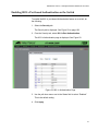
Figure 59: 802.1x Authentication Page...............................................................................................................................177
Figure 60: Modify 802.1x Authentication Page ...................................................................................................................178
Figure 61: Modify 802.1x Authentication Page Expanded ..................................................................................................179
Figure 62: 802.1x View Page..............................................................................................................................................183
Figure 63: 802.1x Authentication Page with Status Enabled ..............................................................................................184
Figure 64: Management Tab...............................................................................................................................................190
Figure 65: IP Management Configuration Page with Static IP Address..............................................................................191
Figure 66: IP Management Configuration Page with DHCP ...............................................................................................193
Figure 67: IPv6 Management Configuration Page..............................................................................................................194
Figure 68: Discovery & Monitoring Tab...............................................................................................................................201
Figure 69: Locations Tab ....................................................................................................................................................202
Figure 70: LLDP Civic Location Page .................................................................................................................................202
Figure 71: LLDP Civic Location Page— Modify..................................................................................................................204
Figure 72: LLDP Coordinate Location Page .......................................................................................................................205
Figure 73: LLDP Coordinate Location Page— Modify ........................................................................................................206
Figure 74: LLDP ELIN Location List Page ..........................................................................................................................208
Figure 75: LLDP ELIN Location Page.................................................................................................................................208
Figure 76: LLDP Configuration Page ..................................................................................................................................211
Figure 77: LLDP Port Config Page .....................................................................................................................................213
Figure 78: Modify LLDP Port Configuration Page...............................................................................................................214
Figure 79: LLDP Port Location Page ..................................................................................................................................215
Figure 80: Modify LLDP Port Location Page.......................................................................................................................216
Figure 81: LLDP TLV Tab ...................................................................................................................................................217
Figure 82: LLDP TLV Page.................................................................................................................................................217
Figure 83: Modify LLDP TLV Page .....................................................................................................................................218
Figure 84: LLDP MED TLV Page........................................................................................................................................220
Figure 85: Modify LLDP Med TLV Page .............................................................................................................................221
Figure 86: LLDP Neighbors Information Page ....................................................................................................................223
Figure 87: LLDP Statistics Page with Port Statistics Tab ...................................................................................................225
Figure 88: LLDP Statistics Page with Summary Tab ..........................................................................................................226
Figure 89: sFlow Page with the Port Configurations Tab....................................................................................................242
Figure 90: sFlow Port Modify Page.....................................................................................................................................243
Figure 91: Sflow Page with Collectors Tab .........................................................................................................................245
Figure 92: Sflow Collector Page .........................................................................................................................................246
10
Preface
This is the web browser management guide for the AT-9000/28, AT-9000/
28SP, and AT-9000/52 Managed Layer 2-4 Gigabit Ethernet EcoSwitches.
The instructions in this guide explain how to start a management session,
use the web interface of the AlliedWare Plus™ Management Software,
and configure the features of the switch.
For hardware installation instructions, refer to the AT-9000 Manager Layer
2 GB EcoSwitch Series Installation Guide.
This preface contains the following sections:
“Document Conventions” on page 12
“Downloading Management Software and Web-based Guides” on
page 13
“Contacting Allied Telesis” on page 14
Caution
The software described in this documentation contains certain
cryptographic functionality and its export is restricted by U.S. law. As
of this writing, it has been submitted for review as a “retail encryption
item” in accordance with the Export Administration Regulations, 15
C.F.R. Part 730-772, promulgated by the U.S. Department of
Commerce, and conditionally may be exported in accordance with
the pertinent terms of License Exception ENC (described in 15
C.F.R. Part 740.17). In no case may it be exported to Cuba, Iran,
Iraq, Libya, North Korea, Sudan, or Syria. If you wish to transfer this
software outside the United States or Canada, please contact your
local Allied Telesis sales representative for current information on
this product’s export status.
11
Preface
Document Conventions
This document uses the following conventions:
Note
Notes provide additional information.
Caution
Cautions inform you that performing or omitting a specific action
may result in equipment damage or loss of data.
Warning
Warnings inform you that performing or omitting a specific action
may result in bodily injury.
12
AlliedWare Plus Version 2.1.2 Management Software Web Browser User’s Guide
Downloading Management Software and Web-based Guides
Both new releases of management software and product documentation
are available from the Allied Telesis web sites. The management software
is available at www.alliedtelesis.com/support/software. To display all of
the network management software for a product, use the pull-down menu
labeled “All” to select a hardware product model such as “AT-9000/28SP.”
Then double click the software version that you want to download onto
your local work station or server.
The installation and user guides for all Allied Telesis products are available
in PDF at www.alliedtelesis.com/support/documentation/. To display
all of the product documentation for a product, use the pull-down menu
labeled “All” to select a hardware product model such as “AT-9000/52.”
Then double click the document that you want to view. You can view the
documents online or download them onto your local workstation or server.
13
Preface
Contacting Allied Telesis
This section provides Allied Telesis contact information for technical
support and for sales and corporate information.
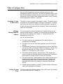
Online Support
Email and
Telephone
Support
For Technical Support via email or telephone, refer to the Allied Telesis
web site at www.alliedtelesis.com. Select your country from the list on
the web site and then select the appropriate tab.
Returning
Products
Products for return or repair must first be assigned a return materials
authorization (RMA) number. A product sent to Allied Telesis without an
RMA number will be returned to the sender at the sender’s expense. For
instructions on how to obtain an RMA number, go to our web site at
www.alliedtelesis.com and then select Support and Replacement
Services.
Sales or
Corporate
Information
You can contact Allied Telesis for sales or corporate information through
our web site at www.alliedtelesis.com.
Management
Software Updates
14
You can request technical support online by accessing the Allied Telesis
Knowledge Base: www.alliedtelesis.com/support/kb.aspx. You can use
the Knowledge Base to submit questions to our technical support staff and
review answers to previously asked questions.
New releases of the management software for our managed products are
available from the Allied Telesis web site: www.alliedtelesis.com. For
downloading instructions, see “Downloading Management Software and
Web-based Guides” on page 13.
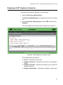
Chapter 1
AlliedWare Plus™ Version 2.1.2 Web
Browser Interface
This chapter describes the types of web management sessions on the
AlliedWare Plus web interface and the web interface manager accounts.
See the following sections:
“Management Sessions” on page 16
“Web Manager Accounts” on page 17
15
Chapter 1: AlliedWare Plus™ Version 2.1.2 Web Browser Interface
Management Sessions
This manual provides procedures that guide you through the AlliedWare
Plus Web interface. The AlliedWare Plus Management Software supports
the AT-9000/28, AT-9000/28SP, and the AT-9000/52 Layer 2-4 Gigabit
Ethernet EcoSwitches in both the web interface and the Command Line
Interface (CLI).
The initial management session of the switch must be from a local (serial
port console) management session because you must assign the switch
an IP address from a local session. After you have assigned an IP address
to the switch and enabled web management, you can log onto the web
with either an encrypted (HTTPS) or a non-encrypted (HTTP) web
browser management session.
In addition, the web interface allows access to a subset of the AlliedWare
Plus features. For access to all of the AlliedWare Plus features, you must
use the CLI.
Detailed feature descriptions are not provided in this guide. For thorough
explanations of the features, see the AlliedWare Plus Management
Software Command Line User’s Guide.
Note
The initial management session of the switch must be from a local
(serial port console) management session.
16
AlliedWare Plus Version 2.1.2 Management Software Web Browser User’s Guide
Web Manager Accounts
You must log on to manage the switch. This requires a valid username and
password. The switch comes with one web manager account with a
username of “manager” and the default password of “friend.” Both
the username and password are case sensitive. This account gives you
access to all management modes and commands.
In the web interface, you can create two additional remote manager
accounts. For instructions, see “Managing User Accounts” on page 45.
The switch supports up to three manager sessions (this is configurable) at
one time.
17
Chapter 1: AlliedWare Plus™ Version 2.1.2 Web Browser Interface
18
Chapter 2
Starting a Management Session
This chapter describes how to start a management session using the
AlliedWare Plus web interface as well as how to select fields, save your
changes, and end a management session. See the following sections:
‘“Starting a Web Management Session” on page 20
“Selecting items from a Web Page” on page 26
“What to Configure First” on page 27
“Saving Your Changes” on page 28
“Ending a Web Management Session” on page 29
19
Chapter 2: Starting a Management Session
Starting a Web Management Session
Before you start a remote web management session, you must log on to
the AlliedWare Plus CLI and assign an IP address to the switch. Also, you
must enable web management on the switch which is disabled by default.
To assign an IP address, enable web management, and start a web
management session on an AT-9000 switch, do the following:
Note
If you have already assigned the switch an IP address and enabled
the web management, start with step 8.
1. Log on to the AlliedWare Plus CLI.
The Login Menu is shown in Figure 1.
Press <ENTER> key to connect...
awplus login:
Figure 1. Login Menu
2. Enter “manager” for the login name and press Return.
You are prompted for a password.
3. Enter “friend” as the password and press Return.
The “awplus>” prompt indicates that you are logged on to the switch.
4. Assign an IP address and subnet mask to the switch by entering the
following commands:
awplus> enable
awplus# configure terminal
awplus(config)# interface vlan1
awplus(config-if)# ip address 167.142.10.5/16
20
AlliedWare Plus Version 2.1.2 Management Software Web Browser User’s Guide
5. Display the IP address assigned to VLAN 1 by entering the following
commands:
awplus(config-if)# exit
awplus(config)# exit
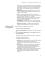
awplus# show ip interface
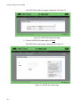
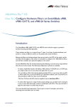
For a display of this command, see Figure 2.
awplus# show ip interface
Interface
vlan1-0
IP-Address
Status
167.142.10.5/16 admin up
Protocol
running
Figure 2. Displaying the IP address
6. Enable the web browser on the switch by entering the following
commands:
awplus# configure terminal
awplus(config)# http server
7. Save your changes on the switch by copying the running configuration
file to the start-up configuration file. Enter the following command:
awplus# copy running-config startup-config
8. Open a web browser, such as Microsoft Explorer, and enter one of the
following:
To start an HTTP session, enter: http:// followed by the IP address
of the switch.
To start an HTTPS session, enter: https:// followed by the IP
address of the switch.
21
Chapter 2: Starting a Management Session
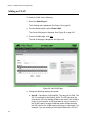
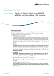
The Login Page is displayed. See Figure 3.
Figure 3. Login Page
9. Enter “manager” in the User Name field and “friend” in the Password
field. Then click the Login button.
22
AlliedWare Plus Version 2.1.2 Management Software Web Browser User’s Guide
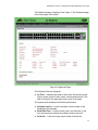
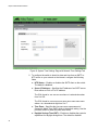
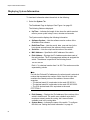
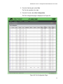
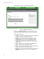
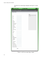
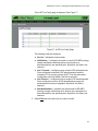
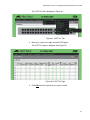
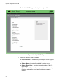
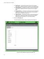
The Dashboard page is displayed. See Figure 4. The Dashboard page
is the home page of the switch.
Figure 4. Dashboard Page
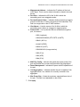
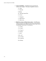
The following fields are displayed:
Up Time— Indicates the length of time since the switch was last
reset or power cycled in days, hours, minutes and seconds. This
field is located in the upper right-hand corner of the page.
The System section displays the following information:
Software Version— Lists the software version number of the
AlliedWare Plus software.
Build Date/Time— Lists the month, date, year and time (in the
hour:minute:second format) the software version was built.
Serial No.— Lists the unique serial number of the switch.
23
Chapter 2: Starting a Management Session
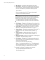
MAC Address— Specifies the MAC address of the switch.
IPv4 Address— Displays the IPv4 address and subnet mask of
the web interface. The IPv4 management address is assigned to
the switch. The address is specified in the following format:
xxx.xxx.xxx.xxx
Each x is a number from 0 to 255. There are four groups of
numbers that are separated by periods.
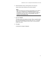
Note
For IPv4 addresses, the subnet mask is a decimal number that
represents the number of bits, from left to right, that constitute the
network portion of the address. Here are some examples:
— The decimal mask 16 is equivalent to the mask 255.255.0.0.
— The decimal mask 24 is equivalent to the mask 255.255.255.0.
IPv4 Gateway— Displays the IPv4 address of the next hop of the
switch’s default route. The switch uses a default route when it must
communicate with a device that is not on the local IPv4 network.
System Name— Indicates the name of the switch. To configure
this field, see “Setting the Switch Information” on page 41.
System Contact— Indicates the contact person for the switch. To
configure this field, see “Setting the Switch Information” on
page 41.
System Location— Indicates the location of the switch. To
configure this field, see “Setting the Switch Information” on
page 41.
Management VLAN— Displays the management VLAN assigned
to the switch. The default VLAN is “VLAN1.”
IPv6 Address— Displays the IPv6 address and subnet mask of
the web interface. An IPv6 management address for the switch is
entered in the following format:
nnnn:nnnn:nnnn:nnnn:nnnn:nnnn:nnnn:nnnn
Where “n” is a hexadecimal digit from 0 to F. The eight groups of
digits are separated by colons. Groups where all four digits are ‘0’
can be omitted. Leading ‘0’s in groups can also be omitted.
For example, the following IPv6 addresses are equivalent:
12c4:421e:09a8:0000:0000:0000:00a4:1c50
12c4:421e:9a8::a4:1c50
24
AlliedWare Plus Version 2.1.2 Management Software Web Browser User’s Guide
IPv6 Gateway— Displays the IPv6 address of the next hop of the
switch’s default route. The switch uses a default route when it must
communicate with a device that is not on the local IPv6 network.
The Services section displays the following information:
SNMP— Indicates the SNMP setting of the switch.
HTTP— Indicates the HTTP setting of the switch
Telnet— Indicates if Telnet is enabled or disabled on the switch.
SSH— Indicates if SSH is enabled or disabled on the switch.
Spanning Tree— Indicates if RSTP or STP is enabled on the
switch. The default setting is “RSTP.”
QoS— Indicates is QoS is enabled or disabled on the switch.
LLDP— Indicates if LLDP is enabled or disabled on the switch.
SFLOW— Indicates is sFlow is enabled or disabled on the switch.
802.1x Port Authentication— Indicates if 802.1x Port
Authentication is enabled or disabled on the switch.
Remote Logging— Indicates if the remote log is enabled or
disabled on the switch.
IGMP Snooping— Indicates if IGMP Snooping is enabled or
disabled on the switch.
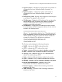
The Administration Options section displays the following information:
System Upgrade— Select this field to upgrade your system
software. See “Upgrading the Software” on page 51.
Reboot— Select this field to reboot the switch. For instructions,
see “Rebooting a Switch” on page 50.
25
Chapter 2: Starting a Management Session
Selecting items from a Web Page
To select a feature or parameter, place your cursor over the selection and
wait for it to turn orange. Then click on the selection.
26
AlliedWare Plus Version 2.1.2 Management Software Web Browser User’s Guide
What to Configure First
Here are a few suggestions on what to configure during your web
management session on the switch. The initial management session must
be a local management session from the Console port on the switch. For
instructions on how to start a local management session, refer to “Starting
a Web Management Session” on page 20.
Assigning a Name
to the Switch
The switch is easier to identify if you assign it a name. The switch’s name
is displayed on the Dashboard page. See Figure 4 on page 23. To change
the name of the switch, see “Setting the Switch Information” on page 41.
A name can be up to 39 alphanumeric characters. Spaces and quotation
marks are not permitted.
Adding a
Management IP
Address
You must assign the switch a management IP address before you can
access the web interface. In addition, you may assign the switch both an
IPv4 and an IPv6 address. See Chapter 17, “Setting IPv4 and IPv6
Management” on page 187.
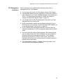
Here are the requirements:
Setting System
Time
The switch can have one management IPv4 address and one
management IPv6 address.
The switch can have one IPv4 default gateway and one IPv6 default
gateway.
A management IP address must be assigned to a VLAN on the switch.
It can be any VLAN, including the Default_VLAN which is “VLAN1.” For
background information on VLANs, refer to the AlliedWare Plus
Version 2.1.1 Command Line User’s Guide.
The network devices (such as, syslog servers, TFTP servers, etc.)
must be members of the same subnet as a management IP address or
have access to it through routers or other Layer 3 devices.
The switch must have a default gateway if the network devices are not
members of the same subnet as the management IP address. The
default gateway specifies the IP address of a router interface that
represents the first hop to the subnets or networks of the network
devices.
A default gateway address, if needed, must be a member of the same
subnet as a management IP address.
To set the system time either manually or with an NTP server, see “Setting
the System Date and Time” on page 32.
27
Chapter 2: Starting a Management Session
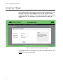
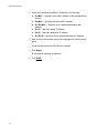
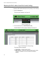
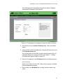
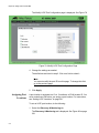
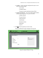
Saving Your Changes
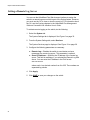
In the web interface, there are two ways to save your changes. After you
complete a procedure, click Apply as shown on the System Contact
Information page. See Figure 5. This saves the information to the running
configuration file. This information is not saved when you reboot the
switch.
Figure 5. System Contact Information Page
To permanently save your changes in the start-up configuration file, click
SAVE at the top of the web page.
28
AlliedWare Plus Version 2.1.2 Management Software Web Browser User’s Guide
Ending a Web Management Session
To end a web management session, select LOGOUT at the top of the web
page. For an example, see the System Contact Information page in Figure
5 on page 28.
29
Chapter 2: Starting a Management Session
30
Chapter 3
Basic Switch Parameters
This chapter describes how to set up basic switch operations in the web
interface. See the following sections:
“Setting the System Date and Time” on page 32
“Setting a Telnet or SSH Server” on page 38
“Setting a Remote Log Server” on page 40
“Setting the Switch Information” on page 41
“Setting the Configuration File” on page 43
“Managing User Accounts” on page 45
“Rebooting a Switch” on page 50
“Upgrading the Software” on page 51
“Returning the AlliedWare Plus Management Software to the Factory
Default Values” on page 53
“Displaying System Information” on page 54
For additional information about basic port settings, see the following
chapters in the AlliedWare Plus Management Software Command Line
Interface User’s Guide:
Chapter 5: Basic Switch Management
Chapter 6: Basic Switch Management Commands
31
Chapter 3: Basic Switch Parameters
Setting the System Date and Time
This procedure explains how to set the switch’s date and time. Setting the
date and time is important if you plan to view the events in the switch’s
event log or send the events to a syslog server. The correct date and time
are also important if the management software sends traps to a
management workstation or if you plan to create a self-signed SSL
certificate. Events, traps, and self-signed certificates should contain the
date and time of when they occurred or, in the case of certificates, when
they were created.
There are two ways to set the switch’s date and time. One method is to set
it manually. This method is not recommended because the date and time
are lost if you reboot the switch.
The second method uses the Simple Network Time Protocol (SNTP). The
AlliedWare Plus Management Software comes with the client version of
this protocol. You can configure the AlliedWare Plus software to obtain the
current date and time from an SNTP or Network Time Protocol (NTP)
server located on your network or the Internet.
SNTP is a reduced version of the NTP. However, the SNTP client software
in the AlliedWare Plus Management Software is interoperable with NTP
servers.
Note
In order for the management software on the switch to communicate
with an SNTP or NTP server, there must be an interface on the local
subnet from where the switch is reaching the server. The switch
uses the IP address of the interface as its source address when
sending packets to the server.
Note
The default system time on the switch is midnight, January 1, 2000.
Choose from the following procedures:
32
“Setting System Time Manually” on page 33
“Setting An SNTP or NTP Server” on page 35
AlliedWare Plus Version 2.1.2 Management Software Web Browser User’s Guide
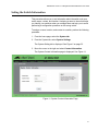
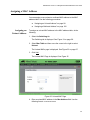
Setting System
Time Manually
To set the system time manually, do the following:
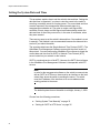
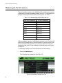
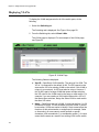
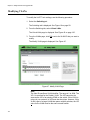
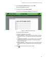
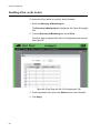
1. Select the System tab.
2. From the System tab, select System Settings.
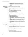
The System Settings Tab is displayed in Figure 6.
Figure 6. System Settings Tab
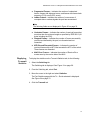
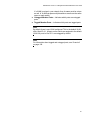
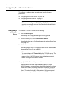
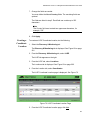
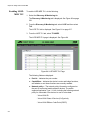
3. Move the cursor to the right and select Time.
The System Time Settings page is displayed. See Figure 7 on page
34.
33
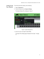
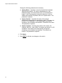
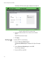
Chapter 3: Basic Switch Parameters
Figure 7. System Time Settings Page
4. There are two ways to set the date and time manually. Use either step
4 or step 5. To type in the system date and time in the Date & Time
field, do the following:
a. Enter the time and date in the following format:
yyyy-dd-mm hh:mm:ss
b. Click Apply.
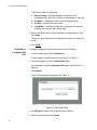
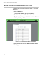
5. Select the calendar icon.
The Calendar page is displayed. See Figure 8 on page 35.
a. Use the arrows at the top of the Calendar to select the month and
year.
b. Click on the day of the month.
c. Set the time of day using the following format:
hh:mm:ss
34
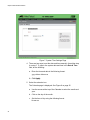
AlliedWare Plus Version 2.1.2 Management Software Web Browser User’s Guide
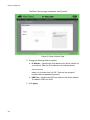
d. Close the Calendar page. See Figure 8.
Figure 8. Calendar Page
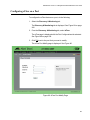
6. Enter the time at the bottom of the page in the hh:mm:ss format.
7. Click Apply
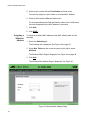
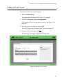
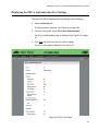
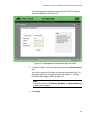
Setting An SNTP
or NTP Server
To configure SNTP or NTP server, do the following:
1. Select the System tab.
The System Settings Tab is displayed. See Figure 6 on page 33.
2. From the System tab, select System Settings.
3. Move the cursor to the right and select Time.
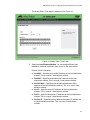
The System Time Settings Page page is displayed. For an example of
this page, see Figure 7 on page 34.
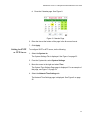
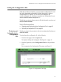
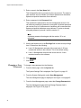
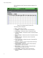
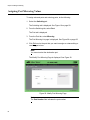
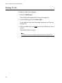
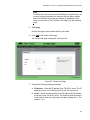
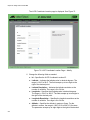
4. Select the Network Time Settings tab.
The Network Time Settings page is displayed. See Figure 9 on page
36.
35
Chapter 3: Basic Switch Parameters
Figure 9. System Time Settings Page with Network Time Settings Tab
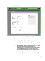
5. To configure the switch to obtain its date and time from an SNTP or
NTP server on your network or the Internet, configure the following
fields:
NTP Status— Enables or disables the SNTP client on the switch.
The default is disabled.
Server IP Address— Specifies the IP address of an SNTP server.
Enter either an IPv4 or IPv6 IP address.
The IPv4 format is: xxx.xxx.xxx.xxx where x is a decimal number
from 0 to 255.
The IPv6 format is: nnnn:nnnn:nnnn:nnnn:nnnn:nnnn:nnnn:nnnn
where n is a hexadecimal digit from 0 to F.
36
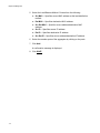
Time Zone— Specifies the time zone as a measurement of
Greenwich Mean Time (GMT) which is the default setting. Use the
pull-down menu to select the other time zones.
Daylight Savings Time (DST)— Enables or disables the system’s
adjustment for daylight savings time. The default is disabled.
AlliedWare Plus Version 2.1.2 Management Software Web Browser User’s Guide
Note
The switch does not set DST automatically. If the switch is in a
locale that uses DST, you must remember to enable this in April
when DST begins and disable it in October when DST ends. If the
switch is in a locale that does not use DST, this option should be set
to disabled all the time.
Note
If the local interface on the switch is obtaining its IP address and
subnet mask from a DHCP server, you can configure the server to
provide the interface with an IP address of an NTP or SNTP server.
If you configured the server to provide this address, then you do not
need to enter it here.
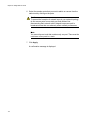
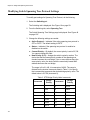
6. When you finish configuring the parameters, click Apply.
If you enabled the SNTP client, the switch immediately polls the SNTP
or NTP server for the current date and time. (When SNTP is enabled,
the switch automatically polls the server whenever a change is made
to any of the fields on this page.)
37
Chapter 3: Basic Switch Parameters
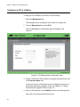
Setting a Telnet or SSH Server
The AlliedWare Plus Web Browser interface allows you to configure the
switch as a Telnet or SSH server.
You can use the web browser interface to enable a Telnet server, but not
as a Telnet client. The Telnet client is only supported from local
management sessions of the switch. For information about how to use a
Telnet client, see the AlliedWare Plus Management Software Command
Line Interface User’s Guide. See Where to Find Management Software
Updates and Product Information on page 13.
To enable an SSH server in the web interface, you must first create an
encryption key in the CLI interface. Then you can enable the SSH server
in the web interface.
The procedures in this section allow you to configure the switch as a
Telnet or SSH server.
To assign the switch to a Telnet or SSH server, do the following:
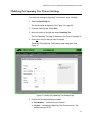
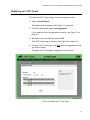
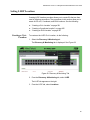
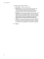
1. From the home page, select the System tab.
The System Settings tab is displayed. See Figure 6 on page 33.
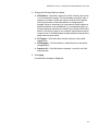
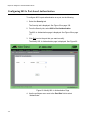
2. From the System Settings tab, select Services.
38
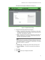
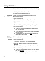
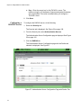
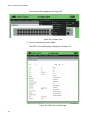
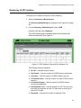
AlliedWare Plus Version 2.1.2 Management Software Web Browser User’s Guide
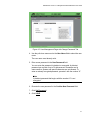
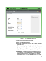
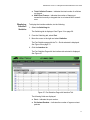
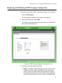
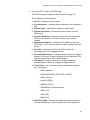
The System Services page is displayed. See Figure 10.
Figure 10. System Services Page
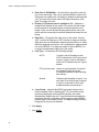
3. Configure the following parameters as necessary:
Telnet— Selecting this field enables a Telnet server on the switch.
To disable a Telnet server on the switch, unclick the box next to the
Telnet field. This parameter is optional.
SSH— Selecting this field enables an SSH server on the switch. To
disable an SSH server on the switch, unclick the box next to the
SSH filed. This parameter is optional.
Note
Both the Remote Log and Server IP Address fields are used only to
set a remote log server. For information on these fields, see “Setting
a Remote Log Server” on page 40.
Remote Log— This field is only used for the remote log server.
Server IP Address— This field is only used for the remote log
server.
4. Click Apply.
5. Click SAVE to save your changes on the switch.
39
Chapter 3: Basic Switch Parameters
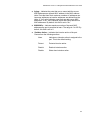
Setting a Remote Log Server
You can use the AlliedWare Plus Web browser interface to assign the
switch to a remote log server which is part of the Syslog feature. However,
you must use the CLI to view or clear the event log. For information about
the CLI, see the SysLog chapters in the AlliedWare Plus Management
Software Command Line Interface User’s Guide.
To activate remote logging on the switch, do the following:
1. Select the System tab.
The System Settings tab is displayed. See Figure 6 on page 33.
2. From the System Settings tab, select Services.
The System Services page is displayed. See Figure 10 on page 39.
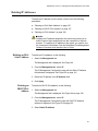
3. Configure the following parameters as necessary:
Remote Log— Enables the switch to send status and error
messages to a remote log server. This parameter is optional.
Server IP Address— Specifies the IP address of the remote log
server. This field is mandatory if you selected the Remote Log field
above. You can enter the IP address in the IPv4 format:
xxx.xxx.xxx.xxx.
where each x is a decimal number from 0 to 255. The numbers are
separated by periods.
4. Click Apply.
5. Click SAVE to save your changes on the switch.
40
AlliedWare Plus Version 2.1.2 Management Software Web Browser User’s Guide
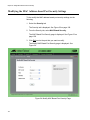
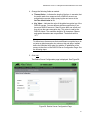
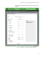
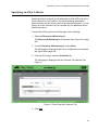
Setting the Switch Information
This procedure allows you to set information about the switch such as a
switch name, contact, and location. Assigning a name to the switch helps
you identify your switches when you manage them and help you to avoid
performing a configuration procedure on the wrong switch.
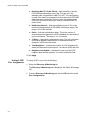
To assign a name, location, and contact to a switch, perform the following
procedure:
1. From the home page, select the System tab.
2. From the System tab, select System Settings.
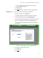
The System Setting tab is displayed. See Figure 6 on page 33.
3. Move the cursor to the right and select Contact Information.
The System Contact Information page is displayed. See Figure 11.
Figure 11. System Contact Information Page
41
Chapter 3: Basic Switch Parameters
Change the following parameters as necessary:
System Name— Specifies a name for the switch (for example,
Sales Ethernet switch). The name is displayed only on the
Dashboard page. The name can be from 1 to 39 characters in
length. It can include spaces and special characters, such as
dashes and asterisks. By default, there is no system name. This
parameter is optional.
System Contact — Specifies the name of the network
administrator responsible for managing the switch. The name can
be from 1 to 20 characters. It can include spaces and special
characters, such as dashes and asterisks. The default is no name.
This parameter is optional.
System Location— Specifies the location of the switch, (for
example, 4th Floor - room 402B). The location can be from 1 to 20
characters. The location can include spaces and special
characters, such as dashes and asterisks. The default is no
location. This parameter is optional.
4. Click Apply.
5. Click SAVE to activate your changes on the switch.
42
AlliedWare Plus Version 2.1.2 Management Software Web Browser User’s Guide
Setting the Configuration File
Within the web browser interface, you can upload a configuration file on to
the switch, download a configuration file from the switch, or delete a
configuration file. In addition, you can save your changes to the
current configuration file. However, to create a new configuration file, you
need to access the switch through the CLI.
The file that you select in this procedure is file that the switch uses the next
time you reboot the switch.
See the following procedures:
Displaying and
Setting the Active
Configuration
File
“Displaying and Setting the Active Configuration File” on page 43
“Uploading a Configuration File” on page 44
The file you select in this procedure is the active configuration file after you
reboot the switch.
To select the active configuration file, do the following:
1. From the home page, click the System tab.
The System Settings tab is displayed. See Figure 6 on page 33.
2. From the System tab, select Configuration Files from the pull-down
menu.
For an example of the Configuration Files page, see Figure 12.
Figure 12. Configuration Files Page
43
Chapter 3: Basic Switch Parameters
The following fields are displayed:
Startup Config— Displays the name of the active boot
configuration file, which for the switch in the example is “boot.cfg.”
File Name— Indicates the name of the configuration files.
File Size— Lists the file size in bytes.
Last Modify— Indicates the date the configuration file was last
modified. The format is year, month, date.
3. Use the pull-down menu to select the active configuration file. Then
click Apply.
The file you select is the active configuration file after you reboot the
switch.
4. Click SAVE.
Uploading a
Configuration
File
To upload a configuration file onto the switch, do the following:
1. From the home page, click the System tab.
For an example of the System tab, see Figure 11 on page 41.
2. From the System tab, select Configuration Files.
For an example of the Configuration Files page, See Figure 12 on
page 43.
3. Click Upload.
The File Upload page is displayed. See Figure 13.
Figure 13. File Upload Page
4. Click Browse to select a file to upload onto the switch.
5. Select the file and then click Upload.
44
AlliedWare Plus Version 2.1.2 Management Software Web Browser User’s Guide
Managing User Accounts
The procedures in this section describe how to create user accounts as
well as change passwords and privileges. There is also a procedure that
describes how to delete a user account. See the following:
Adding a User
“Adding a User” on page 45
“Changing a User Password” on page 46
“Changing the User Privilege” on page 48
“Deleting a User” on page 49
To add a user, do the following:
1. From the home page, click the System tab.
The System Settings tab is displayed, see Figure 6 on page 33.
2. From the System Settings tab, select User Management.
For an example of the User Management page, see Figure 14.
Figure 14. User Management Page
45
Chapter 3: Basic Switch Parameters
3. Enter a name in the User Name field.
This field specifies the log on name for the new account. The name is
case sensitive and can contain up to fifteen alphanumeric characters.
Spaces and special characters are not allowed.
4. Enter a password in the Password field.
This specifies the password for the new management account. You
can enter the password in plaintext or encrypted. A plaintext password
can consist of up to 16 alphanumeric characters and is case-sensitive.
Spaces and special characters are not allowed. To enter an already
encrypted password, precede it with the number “8.”
Note
A plaintext password that begins with the number “8” is not
encrypted.
5. Use the pull-down menu in the Privilege field to select a user privilege
level. Choose from the following:
Level 15: Management accounts with a user level of 15 have
unrestricted access to the software. This is the default setting.
Level 1: Management accounts with a user level of 1 have
restricted access to the software.
6. Click Add User.
7. Click SAVE.
Changing a User
Password
To change a user password, do the following:
1. From the home page, click the System tab.
The System Settings Tab is displayed. See Figure 6 on page 33.
2. From the System Settings tab, select User Management.
The User Management page is displayed. See Figure 14 on page 45.
3. From the User Management page, select the Change Password tab.
The User Management page with the Change Password tab is
displayed. See Figure 15 on page 47.
46
AlliedWare Plus Version 2.1.2 Management Software Web Browser User’s Guide
Figure 15. User Management Page with Change Password Tab
4. Use the pull-down menu next to the User Name field to select the user
name.
The user name must already exist.
5. Enter a new password in the New Password field.
You can enter the password in plaintext or encrypted. A plaintext
password can consist of up to 16 alphanumeric characters and is
case-sensitive. Spaces and special characters are not allowed. To
enter an already encrypted password, precede it with the number “8.”
Note
A plaintext password that begins with the number “8” is not
encrypted.
6. Re-enter the new password in the Confirm New Password field.
7. Click Set Password.
8. Click SAVE.
47
Chapter 3: Basic Switch Parameters
Changing the
User Privilege
To change a privilege of a user, do the following:
1. From the home page, click the System tab.
The System Settings Tab is displayed. See Figure 6 on page 33.
2. From the System Settings tab, select User Management.
The User Management page is displayed. See Figure 14 on page 45.
3. From the User Management page, select the Change Privilege tab.
The User Management page with the Change Privilege tab is
displayed. See Figure 16.
Figure 16. User Management Page with Change Privilege Tab
4. Use the pull-down menu next to the User Name field to select a user.
5. Use the pull-down menu next the New Privilege field to select a user
privilege level. Choose from the following:
48
Level 15: Management accounts with a user level of 15 have
unrestricted access to the software. This is the default setting.
AlliedWare Plus Version 2.1.2 Management Software Web Browser User’s Guide
Level 1: Management accounts with a user level of 1 have
restricted access to the switch.
6. Click Set Privilege.
7. Click SAVE to save your changes to the start-up configuration file.
Deleting a User
To delete a user name from the switch, do the following:
1. From the home page, click the System tab.
The System Settings Tab is displayed. See Figure 6 on page 33.
2. From the System Settings tab, select User Management.
The User Management page is displayed. See Figure 14 on page 45.
3. From the User Management page, select the Delete User tab.
The User Management page with the Delete User tab is displayed.
See Figure 17.
Figure 17. User Management Page with Delete User Tab
4. Use the pull-down menu to select a user.
5. Click Delete User.
6. Click SAVE.
49
Chapter 3: Basic Switch Parameters
Rebooting a Switch
Resetting the switch ends your web browser management session. To
continue managing the switch, you must login again.
Note
All unsaved changes are discarded when you reset a switch. To
save your changes, click SAVE on the home page.
To reboot a switch, perform the following procedure:
1. Select the System Tab.
The System Settings Tab is displayed. See Figure 6 on page 33.
2. From the System Settings tab, select Dashboard.
The Dashboard Page is displayed. See Figure 4 on page 23.
3. Select Reboot at the bottom of the page.
A confirmation prompt is displayed that indicates that the connection to
the web is lost during a reboot.
4. Click OK to reset the switch or Cancel to cancel the procedure.
Note
The switch does not forward packets while it initializes the
AlliedWare Plus software and loads its active configuration file. This
process takes between 20 seconds to 2 minutes to complete,
depending on the number and types of commands in the
configuration file.
50
AlliedWare Plus Version 2.1.2 Management Software Web Browser User’s Guide
Upgrading the Software
You can obtain the latest version of the AlliedWare Plus software from the
Allied Telesis web site. You must have access to a TFTP server from your
PC to upgrade the AlliedWare Plus software on your switch. Allied Telesis
does not include this application with the software. The upgrade process
takes approximately three minutes.
Upgrading the system software on the switch ends your current web
browser management session. To continue managing the switch, you
must login again.
Note
All unsaved changes are discarded when you upgrade the software
on a switch. To save your changes, click SAVE.
To upgrade the AlliedWare Plus software, perform the following
procedure:
1. Open your TFTP server software and provide it with the IP address of
the your PC.
2. Select the System Tab.
The System Settings Tab is displayed. See Figure 6 on page 33.
3. From the System Settings tab, select Dashboard.
The Dashboard Page is displayed. See Figure 4 on page 23.
4. Select System Upgrade at the bottom of the page.
The System Upgrade page is displayed. See Figure 18 on page 52.
51
Chapter 3: Basic Switch Parameters
Figure 18. System Upgrade Page
5. Click Browse to select an image file.
6. Click Open to select a file.
7. Click Start Upgrade to begin the software upgrade or Cancel to
cancel the procedure.
52
AlliedWare Plus Version 2.1.2 Management Software Web Browser User’s Guide
Returning the AlliedWare Plus Management Software to the Factory
Default Values
To reset the AlliedWare Plus Management Software parameters to their
default values, you must use the Command Line Interface. You cannot
reset the management software to its factory settings in the web interface.
For instructions, see Chapter 5: Basic Switch Management in the
AlliedWare Plus Management Software Command Line User’s Guide on
our web site. To locate manuals online, see Where to Find Management
Software Updates and Product Information on page 13.
53
Chapter 3: Basic Switch Parameters
Displaying System Information
To view basic information about the switch, do the following:
1. Select the System Tab.
The Dashboard Page is displayed. See Figure 4 on page 23.
The following fields are displayed:
Up Time— Indicates the length of time since the switch was last
reset or power cycled in days, hours, minutes and seconds.
The System section displays the following information:
Software Version— Lists the software version number of the
AlliedWare Plus software.
Build Date/Time— Lists the month, date, year and time (in the
hour:minute:second format) the software version was built.
Serial No.— Lists the unique serial number of the switch.
MAC Address— Specifies the MAC address of the switch.
IPv4 Address— Displays the IPv4 address and subnet mask of
the web interface. The IPv4 management address to assigned the
switch. The address is specified in the following format:
xxx.xxx.xxx.xxx
Each “x” is a decimal number from 0 to 255. The numbers must be
separated by periods.
Note
For both the IPv4 and IPv6 addresses, the subnet mask is a decimal
number that represents the number of bits, from left to right, that
constitute the network portion of the address. Here are some
examples:
— The decimal mask 16 is equivalent to the mask 255.255.0.0.
— The decimal mask 24 is equivalent to the mask 255.255.255.0
— The IPv6 decimal mask 24 is equivalent to the mask
FFFF:FF00::0.
54
IPv4 Gateway— Displays the IPv4 address of the next hop of the
switch’s default route. The switch uses a default route when it
receives a network packet for routing, but it cannot find an
available route in the routing table.
System Name— Indicates the name of the switch. To configure
this field, see “Setting the Switch Information” on page 41.
AlliedWare Plus Version 2.1.2 Management Software Web Browser User’s Guide
System Contact— Indicates the contact person for the switch. To
configure this field, see “Setting the Switch Information” on
page 41.
System Location— Indicates the location of the switch. To
configure this field, see “Setting the Switch Information” on
page 41.
Management VLAN— Displays the management VLAN assigned
to the switch. The default VLAN is “VLAN1.”
IPv6 Gateway— Displays the IPv6 address of the next hop of the
switch’s default route. The switch uses a default route when it
receives a network packet for routing, but it cannot find an
available route in the routing table.
IPv6 Address— Displays the IPv6 address and subnet mask of
the web interface. An IPv6 management address for the switch is
entered in the following format:
nnnn:nnnn:nnnn:nnnn:nnnn:nnnn:nnnn:nnnn
Where “n” is a hexadecimal digit from 0 to F. The eight groups of
digits are separated by colons. Groups where all four digits are ‘0’
can be omitted. Leading ‘0’s in groups can also be omitted. For
example, the following IPv6 addresses are equivalent:
12c4:421e:09a8:0000:0000:0000:00a4:1c50
12c4:421e:9a8::a4:1c50
The Services section displays the following information:
SNMP— Indicates the SNMP setting of the switch.
HTTP— Indicates the HTTP setting of the switch
Telnet— Indicates if Telnet is enabled or disabled on the switch.
SSH— Indicates if SSH is enabled or disabled on the switch.
Spanning Tree— Indicates if RSTP or STP is enabled on the
switch. The default setting is RSTP.
QoS— Indicates is QoS is enabled or disabled on the switch.
LLDP— Indicates if LLDP is enabled or disabled on the switch.
SFLOW— Indicates is sFlow is enabled or disabled on the switch.
802.1x Port Authentication— Indicates if 802.1x Port
Authentication is enabled or disabled on the switch.
Remote Logging— Indicates if the remote log is enabled or
disabled on the switch.
IGMP Snooping— Indicates if IGMP Snooping is enabled or
disabled on the switch.
55
Chapter 3: Basic Switch Parameters
The Administration Options section displays the following information:
56
System Upgrade— Select this field to upgrade your system
software. See “Upgrading the Software” on page 51.
Reboot— Select this field to reboot the switch. For instructions,
see “Rebooting a Switch” on page 50.
Chapter 4
Setting Port Parameters
This chapter describes how to display and modify the port settings such as
back pressure and flow control. In addition, it provides procedures to
display and modify storm control settings.
This chapter contains the following sections:
“Displaying the Port Parameters” on page 58
“Changing the Port Settings” on page 62
“Displaying the Storm Control Settings” on page 66
“Modifying the Storm Control Settings” on page 68
For additional information about the port parameters and the storm control
feature, see the following chapters in the AlliedWare Plus Management
Software Command Line Interface User’s Guide:
Chapter 7: Port Parameters
Chapter 8: Port Parameter Commands
57
Chapter 4: Setting Port Parameters
Displaying the Port Parameters
The port numbering system in the AlliedWare Plus web browser interface
is different from the port numbering system in the CLI. For an example of
the port numbering equivalents for the first five ports, see Table 1.
Table 1. Port Numbering the Web versus the CLI
Web Port Numbering
CLI Port Numbering
port 1
port 1.0.1
port 2
port 1.0.2
port 3
port 1.0.3
port 4
port 1.0.4
port 5
port 1.0.5
port 5
port 1.0.6
port 7
port 1.0.7
port 8
port 1.0.8
Within the display, there is no differentiation between ports 25 through 28
and ports 25R through 28R. In the web interface, if you want to see if port
25 is connected versus port 25R, go to the home page and look at the
illustration of the switch. For an example of the home page, see Figure 4
on page 23.
To display the settings for all of the switch ports, do the following:
1. Select the Switching tab.
The Switching tab is displayed. See Figure 19.
Figure 19. Switching Tab with Port Tab
58
AlliedWare Plus Version 2.1.2 Management Software Web Browser User’s Guide
2. From the Switching tab, select Port.
The Port tab expands to the right.
3. From the Port tab, select Port Configuration.
The Port Configuration page is displayed. See Figure 20.
Figure 20. Port Configuration Page
59
Chapter 4: Setting Port Parameters
4. The following fields are displayed:
Port— Indicates the port number.
Type— Specifies the if the port is fiber, indicated by 1000-FX, or
copper, indicated by 100-FX.
Status— Indicates if the port is enabled or disabled. The default
setting is “Enabled.” Disabling ports turns off their receivers and
transmitters so that they cannot forward traffic.
Link— Indicates the port has successfully connected to a port on
another switch or unit.
Negotiation— Indicates Autonegotiation. By default,
Autonegotiation is enabled.
Speed— Specifies the speed of the port. The default setting is
“1000-FX” for 1000Mbps. The other possible options are “10” for
10Mbps and “100” for 100Mbps.
Duplex— Indicates the duplex mode of the twisted pair ports or
Auto Negotiation. The three settings are half, full, and Auto
Negotiation.
Polarity— Indicates the port’s wiring configuration is MDI (medium
dependent interface) or MDI-X (medium dependent interface
crossover). This setting only applies to a twisted pair port that is
operating at 10 or 100 Mbps.
Note
You can enable or disable backpressure on ports where you
disabled Auto-Negotiation and set the speeds and duplex modes
manually to 10 or 100 Mbps in half-duplex mode.
60
Back Pressure— Indicates if back pressure is enabled or disabled
on a port. Backpressure is used by ports during periods of packet
congestion to temporarily stop their network counterparts from
transmitting more packets. This prevents a buffer overrun and the
subsequent loss and retransmission of network packets. A port
initiates backpressure by transmitting on the shared link to cause a
data collision, which causes its link partner to cease transmission.
The default setting is “Disabled.”
Back Pressure Limit— Indicates the threshold level for back
pressure on a port. Specifies the number of cells for back
pressure. The default value is 7935 cells.
Flow Control— Indicates if flow control (send and receive) is
enabled or disabled on a port. When flow control is enabled, a port
sends pause packets when it reaches the point of packet
congestion. Also, the port stops transmitting packets when it
receives pause packets from its local or remote counterpart. When
flow control is disabled, the port sends pause packet regardless of
AlliedWare Plus Version 2.1.2 Management Software Web Browser User’s Guide
packet congestion. In addition the port continues transmitting
packets when it receives pause packets from its local or remote
counterpart. The default is “Disabled.”
Flow Control Limit— Indicates the threshold level for flow control
on a port. The default value is 7935.
61
Chapter 4: Setting Port Parameters
Changing the Port Settings
You can change the settings of one port at a time. Use the following
procedure to change the port settings or reset a port to its default value,
To change the port settings, do the following:
1. Select the Switching tab.
The Switching tab is displayed. See Figure 19 on page 58.
2. From the Switching tab, select Port.
The Port tab expands to the right.
3. From the Port tab, select Port Configuration.
The Port Configuration page is displayed. See Figure 20 on page 59.
4. Click Edit next to the port that you want to modify.
The Port Configuration Modify page is displayed. See Figure 21 on
page 63.
62
AlliedWare Plus Version 2.1.2 Management Software Web Browser User’s Guide
Figure 21. Port Configuration Modify Page
5. Configure the following parameters as needed:
Port— Indicates the port number.
Port Type— Indicates the type of port, fiber or copper. You cannot
modify this field.
Status— Indicates if the port is enabled or disabled. Choose
between “Enabled” or “Disabled.” The default setting is “Enabled.”
Disabling ports turns off their receivers and transmitters so that
they cannot forward traffic. You may want to disable a port if there
is a problem with a cable or network device.
Negotiation— Indicates the state of Auto Negotiation on a port.
Select “Auto” to enable Auto Negotiation on a port or “Manual” to
disable Auto Negotiation. The default setting is Auto. When the
setting for this field is “Auto,” the Speed and Duplex fields change
63
Chapter 4: Setting Port Parameters
from white to brown and you cannot select them. To change the
Speed and Duplex Mode fields, change the Negotiation setting to
“Manual.”
Speed— Indicates the port speed. Select 10mb, 100mb, or
1000mb.
Duplex Mode— Sets the set the duplex modes of the twisted pair
ports or activates Auto-Negotiation manually. The settings are half,
full, or Auto Negotiation. Ports operating in half-duplex mode can
either receive or transmit packets, but not both at the same time.
Ports operating in full-duplex can both send and receive packets,
simultaneously.
Polarity— Sets the wiring configuration of the twisted pair ports
when they are operating at 10 or 100 Mbps, in either half- or fullduplex mode.
A twisted pair port that is operating at 10 or 100 Mbps can have
one of two wiring configurations. The configurations are known as
MDI and MDI-X. To forward traffic, a port on the switch and a port
on a network device must have different settings. For instance, the
wiring configuration of a switch port has to be MDI if the wiring
configuration on a port on a network device is MDIX.
To set this parameter on a port, you must set the speed and duplex
mode manually. A port that is using Auto-Negotiation sets its wiring
configuration automatically using auto-MDI/MDIX.
Back Pressure Status— Activates or deactivates back pressure
on the ports. Use this field to enable or disable back pressure on
ports that are operating at 10 or 100 Mbps in half-duplex mode.
Back pressure is used by ports during periods of packet
congestion to temporarily stop their network counterparts from
transmitting more packets. This prevents a buffer overrun and the
subsequent loss and retransmission of network packets. A port
initiates back pressure by transmitting on the shared link to cause
a data collision, which causes its link partner to cease
transmission.
To set back pressure on a port, you must configure the speed and
duplex mode manually. You cannot set back pressure on a port
that is using Auto-Negotiation.
64
Back Pressure Limit (1 - 7935)— Indicates a threshold level for
back pressure on a port. Specifies the number of cells for back
pressure. A cell represents 128 bytes. The range is 1 to 7935 cells.
The default value is 7935 cells.
Flow Control Status— Enables or disables the flow control
feature. By default, flow control is disabled on a port.
AlliedWare Plus Version 2.1.2 Management Software Web Browser User’s Guide
Flow Control Limit (1 - 7935)— Indicates the threshold levels for
flow control on the ports. Specifies the number of cells for flow
control. A cell represents 128 bytes. The range is 1 to 7935 cells.
The default value is 7935 cells.
6. To set the port to the default port value, click Default. Otherwise skip
this step.
7. Click Apply.
8. Click SAVE.
65
Chapter 4: Setting Port Parameters
Displaying the Storm Control Settings
To display the storm control settings, do the following:
1. Select the Switching tab.
The Switching tab is displayed. See Figure 19 on page 58.
2. From the Switching tab, select Port.
The Port tab expands to the right.
3. From the Port tab, select Storm Control.
The Storm Control List page is displayed. See Figure 22.
Figure 22. Storm Control List Page
The following fields are displayed:
66
Port Id— Indicates the port number.
Broadcast— Indicates Broadcast packets are received, indicated
by “ON,” or not received, indicated by “OFF,” by the port. By
default, Broadcast packets are not received by a port.
Broadcast Level— Specifies the maximum number of ingress
packets per second of broadcast packets the port will forward. The
range is 0 to 33,554,431 packets. The default is 33,554,431
packets.
Multicast— Indicates Multicast packets are “ON” or “OFF” on the
port. By default, Multicast packets are not received by a port.
AlliedWare Plus Version 2.1.2 Management Software Web Browser User’s Guide
Multicast Level— Specifies the maximum number of ingress
packets per second of multicast packets the port will forward. The
range is 0 to 33,554,431 packets. The default is 33,554,431
packets.
Dlf— Indicates unknown unicast packets are “ON” or “OFF” on the
port. By default, the setting is “ON” indicating that unknown unicast
packets are received by a port.
Dlf Level— Specifies the maximum number of ingress packets per
second of unknown unicast packets the port forwards. The range is
0 to 33,554,431 packets. The default is 33,554,431 packets.
67
Chapter 4: Setting Port Parameters
Modifying the Storm Control Settings
To modify the storm control settings, do the following:
1. Select the Switching tab.
The Switching tab is displayed. See Figure 19 on page 58.
2. From the Switching tab, select Port.
The Port tab expands to the right.
3. From the Port tab, select Storm Control.
The Storm Control List page is displayed. See Figure 20 on page 59.
4. Click Edit on the port that you want to modify.
The Storm Control Settings page is displayed. See Figure 23.
Figure 23. Storm Control Settings Page
68
AlliedWare Plus Version 2.1.2 Management Software Web Browser User’s Guide
5. Change the following fields as needed:
Port Number— Indicates the port number.
Broadcast— Indicates Broadcast packets are received, indicated
by “ON,” or not received, indicated by “OFF,” by the port. By
default, Broadcast packets are not received by a port.
Broadcast Level— Specifies the maximum number of ingress
packets per second of broadcast packets the port will forward. The
range is 0 to 33,554,431 packets. The default is 33,554,431
packets.
Multicast— Indicates Multicast packets are “ON” or “OFF” on the
port. By default, this field is set to “OFF” which indicates Multicast
packets are not received by a port.
Multicast Level— Specifies the maximum number of ingress
packets per second of multicast packets the port forwards. The
range is 0 to 33,554,431 packets. The default is 33,554,431
packets.
DLF— Indicates unknown unicast packets are “ON” or “OFF” on
the port. By default, the setting is “ON” indicating that unknown
unicast packets are received by a port.
DLF Level— Specifies the maximum number of ingress packets
per second of unknown unicast packets the port forwards. The
range is 0 to 33,554,431 packets. The default is 33,554,431
packets.
6. Click Apply.
7. Click SAVE.
69
Chapter 4: Setting Port Parameters
70
Chapter 5
Setting Port Statistics
This chapter describes how to display and clear port statistics. Within the
AlliedWare Plus software, you can display and clear transmit, receive, and
interface port statistics.
This chapter contains the following topics:
“Displaying Port Statistics” on page 72
“Clearing Port Statistics” on page 79
For additional information about port statistics, see the following chapters
in the AlliedWare Plus Management Software Command Line Interface
User’s Guide:
Chapter 7: Port Parameters
Chapter 8: Port Parameter Commands
71
Chapter 5: Setting Port Statistics
Displaying Port Statistics
You can display several types of port statistics. See the following sections:
Displaying
Transmit and
Receive Port
Statistics
“Displaying Transmit and Receive Port Statistics” on page 72
“Displaying the Receive Statistics” on page 73
“Displaying Transmit Statistics” on page 75
“Displaying Interface Statistics” on page 77
To display the transmit and receive statistics for all of the switch ports, do
the following:
1. Select the Switching tab.
The Switching tab is displayed. See Figure 19 on page 58.
2. From the Switching tab, select Port.
3. Move the cursor to the right and select Statistics.
The Port Statistics page is displayed with the Tx + Rx tab automatically
selected. See Figure 24.
Figure 24. Port Statistics Page with Tx + Rx Tab
72
AlliedWare Plus Version 2.1.2 Management Software Web Browser User’s Guide
The following fields are displayed:
Displaying the
Receive Statistics
Port— Indicates the port number.
0-64 Byte Frames— The number of frames transmitted by the port
that contain 0 to 64 bytes.
65-127 Byte Frames— The number of frames transmitted by the
port that contain 65 to 127 bytes.
128-255 Byte Frames— The number of frames transmitted by the
port that contain 128 to 255 bytes.
256-511 Byte Frames— The number of frames transmitted by the
port that contain 256 to 511 bytes.
512-1023 Byte Frames—The number of frames transmitted by the
port that contain 512 to 1023 bytes.
1024-1518 Byte Frames— The number of frames transmitted by
the port that contain 1024 to 1518 bytes.
1519-1522 Byte Frames— The number of frames transmitted by
the port that contain 1519 to 1522 bytes.
To display the statistics on the Receive Statistics tab, do the following:
1. Select the Switching tab.
The Switching tab is displayed. See Figure 19 on page 58.
2. From the Switching tab, select Port.
3. Move the cursor to the right and select Statistics.
The Port Statistics page with the Tx + Rx tab selected is displayed.
See Figure 24 on page 72.
4. Click on the Receive Tab.
The Port Statistics with the Receive tab selected is displayed. See
Figure 25 on page 74.
73
Chapter 5: Setting Port Statistics
Figure 25. Port Statistics with the Receive Tab
The following fields are displayed:
74
Port— Indicates the port number.
Total Bytes— Indicates the number of received bytes.
Total Frames— Indicates the number of received frames.
Total Error Frames— Indicates the total number of received
frames with errors.
Multicast Frames— Indicates the number of received multicast
frames.
Broadcast Frames— Indicates the number of received broadcast
frames.
CRC Frame Errors— Indicates the number of frames with a cyclic
redundancy check (CRC) error but with the proper length (64 1518 bytes) received by the port.
FSC Frame Errors— Indicates the number of ingress frames that
had frame check sequence (FCS) errors.
Pause Frames— Indicates the number of received flow control
pause frames.
Oversize Frames— Indicates the number of received frames that
exceeded the maximum size as specified by IEEE 802.3 (1518
bytes including the CRC).
AlliedWare Plus Version 2.1.2 Management Software Web Browser User’s Guide
Fragmented Frames— Indicates the number of undersized
frames, frames with alignment errors, and frames with frame check
sequence (FCS) errors (CRC errors).
Jabber Frames— Indicates the number of occurrences of
corrupted data or useless signals the port has encountered.
Note
The following fields are not displayed in Figure 25 on page 74.
Displaying
Transmit
Statistics
Undersize Frames— Indicates the number of received frames that
were less than the minimum length as specified by IEEE 802.3 (64
bytes including the CRC).
Dropped Frames— Indicates the number of frames successfully
received and buffered by the port, but discarded and not
forwarded.
MTU Exceed Discarded Frames— Indicates the number of
received frames with an MTU that exceeds the MTU of the switch.
These frames are discarded.
MAC Error Frames— Indicates the number of Receive Error
events seen by the receive side of the MAC.
To display the statistics on the Transmit Statistics tab, do the following:
1. Select the Switching tab.
The Switching tab is displayed. See Figure 19 on page 58.
2. From the Switching tab, select Port.
3. Move the cursor to the right and select Statistics.
The Port Statistics page with the Tx + Rx tab selected is displayed.
See Figure 24 on page 72.
4. Click the Transmit tab.
75
Chapter 5: Setting Port Statistics
The Port Statistics with the Transmit tab selected is displayed. See
Figure 26.
Figure 26. Port Statistics with the Transmit Tab
The following fields are displayed:
76
Port— Indicates the port number.
Total Bytes— Indicates the number of transmitted bytes.
Total Frames— Indicates the number of transmitted frames.
Total Error Frames— Indicates the number of transmitted frames
with errors.
Multicast Frames— Indicates the number of transmitted multicast
frames.
Broadcast Frames— Indicates the number of transmitted
broadcast frames.
Pause Frames Sent— Indicates the number of transmitted flow
control pause frames.
Deferred— Indicates the number of egress frames that the port
could not immediately transmit.
Single Collision— Indicates the number of frames that were
transmitted after at least one collision.
Multi Collision— Indicates the number of frames that were
transmitted after more than one collision.
Late Collision— Indicates the number of late collisions.
Excessive Collision— Indicates the number of excessive
collisions.
AlliedWare Plus Version 2.1.2 Management Software Web Browser User’s Guide
Displaying
Interface
Statistics
Total Collision Frames— Indicates the total number of collisions
on the port.
MAC Error Frames— Indicates the number of frames not
transmitted correctly or dropped due to an internal MAC transmit
error.
To display the interface statistics, do the following:
1. Select the Switching tab.
The Switching tab is displayed. See Figure 19 on page 58.
2. From the Switching tab, select Port.
3. Move the cursor to the right and select Statistics.
The Port Statistics page with the Tx + Rx tab selected is displayed.
See Figure 24 on page 72.
4. Click the Interface tab.
The Port Statistics Page with the Interface tab selected is displayed.
See Figure 27.
Figure 27. Port Statistics Page with Interface Tab
The following fields are displayed:
Port— Indicates the port number.
Rx Unicast Packets— Indicates the number of ingress unicast
packets.
77
Chapter 5: Setting Port Statistics
78
Rx Discard Packets— Indicates the number of ingress packets
that were discarded prior to transmission because of an error.
Rx IP Header Error Packets— Indicates the number of ingress
packets that were discarded because of a hardware error.
Tx Unicast Packets— Indicates the number of egress unicast
packets.
Tx Discard Packets— Indicates the number of egress packets
that were discarded prior to transmission because of an error.
Tx Error Packets— Indicates the number of egress error packets.
AlliedWare Plus Version 2.1.2 Management Software Web Browser User’s Guide
Clearing Port Statistics
To clear the statistics for a port, do the following:
1. Select the Switching tab.
The Switching tab is displayed. See Figure 19 on page 58.
2. From the Switching tab, select Port.
3. Move the cursor to the right and select Statistics.
The Port Statistics Page with Tx + Rx tab selected is displayed. See
Figure 24 on page 72.
4. Select the desired Port Statistics tab. Choose from the following:
Tx+Rx— Displays the transmit and receive statistics. (This is the
default.)
Receive— Displays the receive statistics.
Transmit— Displays the transmit statistics.
Interface— Displays the interface statistics.
5. Click Clear on the port that you want to clear.
79
Chapter 5: Setting Port Statistics
80
Chapter 6
Setting Port Mirroring
The port mirror is a management tool that allows you to monitor the traffic
on one or more ports on the switch. It works by copying the traffic from
designated ports to another port where the traffic can be monitored with a
network analyzer. The port mirror can be used to troubleshoot network
problems or to investigate possible unauthorized network access. The
performance and speed of the switch is not affected by the port mirror.
This chapter provides a brief description of the port mirroring feature and
explains how to display and set port mirroring. See the following sections:
“Overview” on page 82
“Displaying Port Mirroring Settings” on page 83
“Assigning a Destination Port” on page 85
“Assigning Port Mirroring Values” on page 86
For more information about port mirroring, see the following chapters in the
AlliedWare Plus Management Software Command Line Interface User’s
Guide:
Chapter 17: Port Mirror
Chapter 18: Port Mirror Commands
Chapter 6: Setting Port Mirroring
Overview
To use the port mirroring feature, you must designate one or more source
ports and one destination port. The source ports are the ports whose
packets are mirrored and monitored. The destination port is the port where
the packets from the source ports are copied and where the network
analyzer is connected. There can be only one destination port on the
switch.
Here are guidelines for setting the port mirroring feature:
82
The switch supports only one port mirror.
The port mirror can have one destination port.
The port mirror can have more than one source port. This allows you
to monitor the traffic on multiple ports at the same time. For example,
you might monitor the traffic on all the ports of a particular VLAN.
You can mirror the ingress traffic, the egress traffic, or both on the
source ports.
The destination port must not be a member of a static port trunk or an
LACP trunk.
AlliedWare Plus Version 2.1.2 Management Software Web Browser User’s Guide
Displaying Port Mirroring Settings
To display the port mirroring assignments for all of the switch ports, do the
following:
1. Select the Switching tab.
The Switching tab is displayed. See Figure 19 on page 58.
2. From the Switching tab, select Port.
The Port tab is displayed.
3. From the Port tab, select Mirroring.
4. Move the cursor to the right and select Mirroring.
The Port Mirroring List page is displayed. See Figure 28.
Figure 28. Port Mirroring List Page
The following fields are displayed:
Destination Port— Specifies the port where the packets from the
source ports are copied and where the network analyzer is
connected. There can be only one destination port assigned to the
switch. In Figure 28, the Destination Port is port 1.
Port Number— Indicates the port number.
Mirror Transmit— Indicates a source port whose transmitted, or
egress, packets are mirrored and monitored. There can be multiple
source ports on the switch.
83
Chapter 6: Setting Port Mirroring
84
Mirror Receive— Indicates a source port whose received, or
ingress, packets are mirrored and monitored. There can be
multiple source ports on the switch.
AlliedWare Plus Version 2.1.2 Management Software Web Browser User’s Guide
Assigning a Destination Port
The destination port is the source port where the information from the
mirror transmit and mirror receive ports is copied. You must assign the
destination port before the mirror transmit and mirror receive ports. Also,
you can only assign one destination port to the switch.
To assign a destination port, do the following:
1. Select the Switching tab.
The Switching tab is displayed. See Figure 19 on page 58.
2. From the Switching tab, select Port.
The Port tab is displayed.
3. From the Port tab, select Mirroring.
The Port Mirroring List page is displayed. See Figure 28 on page 83.
4. Select the pull-down menu next to the Destination Port field at the top
of the page.
5. Click on the port that you want to designate as the destination port.
You can only assign one destination port to a switch.
6. Click Apply.
The Edit option is removed from the port. This indicates the
destination port for the switch.
7. Click SAVE.
85
Chapter 6: Setting Port Mirroring
Assigning Port Mirroring Values
To assign mirrored ports and mirroring ports, do the following:
1. Select the Switching tab.
The Switching tab is displayed. See Figure 19 on page 58.
2. From the Switching tab, select Port.
The Port tab is displayed.
3. From the Port tab, select Mirroring.
The Port Mirroring List page is displayed. See Figure 28 on page 83.
4. Click Edit next to the port that you want to assign as a transmitting or
receiving port mirror.
Note
You cannot select the destination port.
The Modify Port Mirroring Page is displayed. See Figure 29
Figure 29. Modify Port Mirroring Page
Note
The Port Number field indicates the port number.
86
AlliedWare Plus Version 2.1.2 Management Software Web Browser User’s Guide
5. Select the type of mirroring for the port. The choices are:
None— Specifies the port is not a source port.
Send— Specifies the port is a transmitting, or egress, source port.
Receive— Specifies the port is a receiving, or ingress, source port.
Both— Specifies the port is both a transmitting and a receiving
source port.
By default, there is no mirror port assigned.
6. Click Apply.
7. Click SAVE.
87
Chapter 6: Setting Port Mirroring
88
Chapter 7
Setting the Port Spanning Tree Protocol
The Spanning Tree Protocol (STP) and the Rapid Spanning Tree Protocol
(RSTP) guard against the formation of loops in an Ethernet network
topology. A topology has a loop when two or more nodes can transmit
packets to each other over more than one data path. Packets can become
caught in repeating cycles, referred to as broadcast storms, that
needlessly consume network bandwidth and that can significantly reduce
network performance.
This chapter provides a brief description of the spanning tree protocols and
explains how to set spanning tree on a port. See the following sections:
“Overview” on page 90
“Displaying Port Spanning Tree Protocol Settings” on page 91
“Modifying Port Spanning Tree Protocol Settings” on page 93
Note
For information about how to set a spanning tree protocol for the
switch, see Chapter 12, “Setting Switch Spanning Tree Protocols” on
page 135.
For more information about the spanning tree protocols, see the following
chapters in the AlliedWare Plus Management Software Command Line
Interface User’s Guide:
Chapter 35: Spanning Tree and Rapid Spanning Tree Protocols
Chapter 36: Spanning Tree Protocol (STP)
Chapter 37: STP Commands
Chapter 38: Rapid Spanning Tree Protocol (RSTP)
Chapter 39: RSTP Commands
89
Chapter 7: Setting the Port Spanning Tree Protocol
Overview
STP and RSTP prevent loops from forming by ensuring that only one path
exists between the end nodes in your network. Where multiple paths exist,
these protocols place the extra paths in a standby or blocking mode. In
addition, STP and RSTP can activate redundant paths if primary paths go
down. These protocols guard against multiple links between segments
and the risk of broadcast storms and maintain network connectivity by
activating backup redundant paths.
One of the primary differences between the two protocols is in the time
each takes to complete the process referred to as convergence. When a
change is made to the network topology, such as the addition of a new
bridge, a spanning tree protocol determines whether there are redundant
paths that must be blocked to prevent data loops, or activated to maintain
communications between the various network segments. This is the
process of convergence.
With STP, convergence can take up to a minute to complete in a large
network. This can result in the loss of communication between various
parts of the network during the convergence process, and the subsequent
lost of data packets.
RSTP is much faster than STP. It can complete a convergence in
seconds, and so greatly diminish the possible impact the process can
have on your network. Only one spanning tree can be active on the switch
at a time. The default setting is RSTP.
90
AlliedWare Plus Version 2.1.2 Management Software Web Browser User’s Guide
Displaying Port Spanning Tree Protocol Settings
To display the Spanning Tree Protocol settings for all of the switch ports,
do the following:
1. Select the Switching tab.
The Switching tab is displayed. See Figure 19 on page 58.
2. From the Switching tab, select Port.
3. Move the cursor to the right and select Spanning Tree.
The Port Spanning Tree Settings page is displayed. See Figure 30.
Figure 30. Port Spanning Tree Settings Page
The following fields are displayed:
Port Number— Indicates the port number.
Path Cost— Indicates the cost of a port to the root bridge. This
cost is combined with the costs of the other ports in the path to the
root bridge, to determine the total path cost. The lower the numeric
value, the higher the priority of the path. The range is 6 to 40.
Priority (0-15)— Indicates a bridge priority number for the switch.
The device with the lowest priority number in the spanning tree
91
Chapter 7: Setting the Port Spanning Tree Protocol
domain becomes the root bridge. If two or more devices have the
same priority value, the device with the numerically lowest MAC
address becomes the root bridge.
92
Version— Indicates the Spanning Tree Protocol version. Choose
from STP or RSTP. The default setting is RSTP.
Edge Port— Indicates edge ports on the switch. Edge ports are
not connected to spanning tree devices or to LANs that have
spanning tree devices. As a consequence, edge ports do not
receive BPDUs. If an edge port starts to receive BPDUs, it is no
longer considered an edge port by the switch.
Link Type— Designates point-to-point ports and shared ports.
Loop Guard— Indicates the BPDU loop-guard feature on the
ports is enabled (ON) or disabled (OFF). If a port that has this
feature activated stops receiving BPDU packets, the switch
automatically disables it. A port that has been disabled by the
feature remains in that state until it begins to receive BPDU
packets again or the switch is reset. The default setting for BPDU
loop-guard on the ports is disabled.
AlliedWare Plus Version 2.1.2 Management Software Web Browser User’s Guide
Modifying Port Spanning Tree Protocol Settings
To modify port settings for Spanning Tree Protocol, do the following:
1. Select the Switching tab.
The Switching tab is displayed. See Figure 19 on page 58.
2. From the Switching tab, select Port.
3. Move the cursor to the right and select Spanning Tree.
The Port Spanning Tree page is displayed. See Figure 30 on page 91.
4. Click Edit on the port that you want to change.
The Modify Port Spanning Tree Settings page is displayed. See
Figure 31.
Figure 31. Modify Port Spanning Tree Settings Page
5. Change the following settings as needed:
Port Number— Indicates the port number.
Version— Indicates the Spanning Tree Protocol version. The
default setting is RSTP.
93
Chapter 7: Setting the Port Spanning Tree Protocol
Path Cost (1-200000000)— Use this field to specify the cost of a
port to the root bridge. This cost is combined with the costs of the
other ports in the path to the root bridge, to determine the total path
cost. The lower the numeric value, the higher the priority of the
path. The range is 6 to 40.
Priority (0-15) (Actual value is multiple of 16)— Indicates a
bridge priority number for the switch. The device with the lowest
priority number in the spanning tree domain becomes the root
bridge. If two or more devices have the same priority value, the
device with the numerically lowest MAC address becomes the root
bridge.
Edge Port— Designates the edge ports on the switch. Choose
“Yes” to active an edge type or “No” to make an edge port inactive.
Edge ports are not connected to spanning tree devices or to LANs
that have spanning tree devices. As a consequence, edge ports do
not receive BPDUs. If an edge port starts to receive BPDUs, it is
no longer considered an edge port by the switch.
Link Type— Choose from the following settings:
AUTO
If a port is set to full-duplex mode,
AUTO indicates the Link Type is pointto-point. If a port is set to half-duplex
mode, AUTO indicates the Link Type is
shared.
PTP (point-to-point)
Allows for rapid transition of a port to
the forwarding state during the
convergence process of the spanning
tree domain.
Shared
Disables rapid transition of a port. You
may want to set thelink type to shared
if a port is connected to a hub with
multiple switches connected to it.
Loop Guard— Indicates the BPDU loop-guard feature on the
ports is enabled (ON) or disabled (OFF). If a port with the loop
guard activated stops receiving BPDU packets, the switch
automatically disables the port. A port that has been disabled by
the feature remains in that state until it begins to receive BPDU
packets again or the switch is reset. The default setting for BPDU
loop-guard on the ports is disabled.
6. Click Apply.
7. Click SAVE.
94
Chapter 8
Setting the MAC Address
The procedures in this chapter describe how to display the MAC address
table that resides on the switch as well as how to add an unicast or
multicast MAC addresses to the table. Procedures to modify and delete
MAC addresses within the table are also included in this chapter.
See the following sections:
“Displaying the MAC Address” on page 96
“Assigning a MAC Address” on page 99
“Deleting a MAC Address” on page 102
For more information about MAC addresses, see the following chapters in
the AlliedWare Plus Management Software Command Line Interface
User’s Guide:
Chapter 13: MAC Address Table
Chapter 14: MAC Address Table Commands
95
Chapter 8: Setting the MAC Address
Displaying the MAC Address
You can display both the unicast and multicast addresses in the MAC
address table. See the following procedures:
Displaying the
Unicast MAC
Addresses
“Displaying the Unicast MAC Addresses” on page 96
“Assigning a MAC Address” on page 99
To display the unicast MAC addresses, do the following:
1. Select the Switching Tab.
The Switching Tab is displayed. See Figure 32.
Figure 32. Switching Tab
2. Select Mac Table and then move the cursor to the right to select
Unicast.
The Unicast MACs page is displayed. See Figure 33 on page 97.
96
AlliedWare Plus Version 2.1.2 Management Software Web Browser User’s Guide
Figure 33. Unicast MACs Page
The following fields are displayed:
Displaying
Multicast
Addresses
MAC Address— Indicates the dynamic or static unicast MAC
address learned on or assigned to the port.
Vlan— The ID number of the VLAN where the node designated by
the MAC address is a member. The default VLAN is Vlan1.
Port— Indicates the port where the address was learned or
assigned.
Type— Indicates the type of MAC address, static or dynamic.
To display the multicast addresses in the MAC address table, do the
following:
1. Select the Switching tab.
The Switching tab is displayed. See Figure 32 on page 96.
2. Select Mac Table and then move the cursor to the right to select
Multicast.
The Multicast MACs Page is displayed. See Figure 34 on page 98.
97
Chapter 8: Setting the MAC Address
Figure 34. Multicast MACs Page
The following fields are displayed:
98
MAC Address— Indicates the dynamic or static unicast MAC
address learned on or assigned to the port.
Vlan— Specifies the ID number of the VLAN where the multicast
application and the host nodes are members. The default VLAN is
Vlan1.
Port— Indicates the port where the address was learned or
assigned.
Type— Indicates the type of MAC address: static or dynamic.
AlliedWare Plus Version 2.1.2 Management Software Web Browser User’s Guide
Assigning a MAC Address
You can assign a new unicast or multicast MAC address to the MAC
address table. See the following procedures:
Assigning an
Unicast Address
“Assigning an Unicast Address” on page 99
“Assigning a Multicast Address” on page 100
To assign an unicast MAC address to the MAC address table, do the
following:
1. Select the Switching tab.
The Switching tab is displayed. See Figure 19 on page 58.
2. Select Mac Table and then move the cursor to the right to select
Unicast.
The Unicast MACs page is displayed. See Figure 33 on page 97.
3. Click Add.
The Unicast MAC Page is displayed. See Figure 35
Figure 35. Unicast MAC Page
4. Enter a unicast MAC address in the Mac Address field. Use the
following format: xx:xx:xx:xx:xx:xx
99
Chapter 8: Setting the MAC Address
5. Select a port number with the Port Number pull-down menu.
You can only assign one port number to a unicast MAC address.
6. Select a VLAN with the Vlan pull-down menu.
For a unicast address, this field specifies the name of the VLAN where
the node designated by the MAC address is a member.
7. Click Add.
8. Click SAVE.
Assigning a
Multicast
Address
To assign an multicast MAC address to the MAC address table, do the
following:
1. Select the Switching tab.
The Switching tab is displayed. See Figure 19 on page 58.
2. Select Mac Table and then move the cursor to the right to select
Multicast.
The Multicast MACs Page is displayed. See Figure 34 on page 98.
3. Click Add.
The Multicast Mac Address Page is displayed. See Figure 36.
Figure 36. Multicast Mac Address Page
100
AlliedWare Plus Version 2.1.2 Management Software Web Browser User’s Guide
4. To assign a MAC Address, enter a multicast MAC address in the Mac
Address field. Use the following format: xx:xx:xx:xx:xx:xx
5. Select a port list with the Port List pull-down menu.
For a multicast address, you can assign more than one port number.
Enter multiple ports separated by commas. Or, enter a range of ports
separated by a dash.
6. Select a VLAN with the Vlan pull-down menu.
For a multicast address, this field specifies the name of the VLAN
where the node designated by the MAC address is a member.
7. Click Add.
8. Click SAVE.
101
Chapter 8: Setting the MAC Address
Deleting a MAC Address
To delete a MAC address from the MAC address table, see the following
procedures:
Deleting a
Unicast Address
“Deleting a Unicast Address” on page 102
“Deleting a Multicast Address” on page 102
To delete a unicast address or clear all static or dynamic unicast
addresses, do the following:
1. Select the Switching tab.
The Switching tab is displayed. See Figure 32 on page 96.
2. Select Mac Table and then move the cursor to the right to select
Unicast.
The Unicast MACs page is displayed. See Figure 33 on page 97.
3. Do one of the following:
Deleting a
Multicast
Address
To clear all of the static unicast addresses in the MAC address
table, click Clear Static.
To clear the dynamic unicast addresses in the MAC address table,
click Clear Dynamic.
To delete a specific MAC address, click Delete next to the MAC
address that you want to delete.
To delete a multicast address or clear all static or dynamic multicast
addresses, do the following:
1. Select the Switching Tab.
The Switching Tab is displayed. See Figure 32 on page 96.
2. Select Mac Table and then move the cursor to the right to select
Multicast.
The Multicast MACs page is displayed. See Figure 34 on page 98.
3. Do one of the following:
102
To clear all of the static multicast addresses in the MAC address
table, click Clear Static.
To clear all of the dynamic multicast addresses in the MAC
address table, click Clear Dynamic.
AlliedWare Plus Version 2.1.2 Management Software Web Browser User’s Guide
To delete a specific MAC address, click Delete next to the MAC
address that you want to delete.
103
Chapter 8: Setting the MAC Address
104
Chapter 9
Setting LACP
The Link Aggregation Control Protocol (LACP) is used to increase the
bandwidth between the switch and other LACP-compatible devices by
grouping ports together to form single virtual links.
This chapter provides a brief description of LACP and explains how to
display and set LACP. See the following sections:
“Overview” on page 106
“Displaying LACP Trunks” on page 107
“Adding an LACP Trunk” on page 109
“Modifying an LACP Trunk” on page 111
“Deleting an LACP Trunk” on page 113
For more information about LACP trunks, see the following chapters in the
AlliedWare Plus Management Software Command Line Interface User’s
Guide:
Chapter 33: Link Aggregation Control Protocol (LACP)
Chapter 34: LACP Commands
105
Chapter 9: Setting LACP
Overview
LACP trunks are similar in function to static port trunks, but they are more
flexible. The implementations of static trunks tend to be vendor specific
and so may not always be compatible. In contrast, the implementation of
LACP in the switch is compliant with the IEEE 802.3ad standard. It is
interoperable with equipment from other vendors that also comply with the
standard. This makes it possible to create LACP trunks between the
switch and network devices from other manufacturers.
The main component of an LACP trunk is an aggregator. An aggregator is
a group of ports on the switch. The ports of an aggregator are further
grouped into a trunk, referred to as an aggregate trunk. An aggregator
can have only one trunk. You have to create a separate aggregator for
each trunk on the switch.
An aggregate trunk can consist of any number of ports on the switch, but
only a maximum of eight ports can be active at a time. If an aggregate
trunk contains more ports than can be active at one time, the extra ports
are placed in standby mode. Ports in standby mode do not pass network
traffic, but they do transmit and accept LACP data unit (LACPDU) packets,
which the switch uses to search for LACP-compliant devices.
106
AlliedWare Plus Version 2.1.2 Management Software Web Browser User’s Guide
Displaying LACP Trunks
To display the LACP trunk assignments for all of the switch ports, do the
following:
1. Select the Switching tab.
The Switching tab is displayed. See Figure 19 on page 58.
2. From the Switching tab, select Link Aggregation.
For an example of the Link Aggregation selection, see Figure 37.
Figure 37. Switching Tab with Link Aggregation Selected
3. Move the cursor to the right and select LACP.
The LACP Trunks page is displayed. See Figure 38.
Figure 38. LACP Trunks Page
107
Chapter 9: Setting LACP
4. The following fields are displayed:
108
Aggregator ID— Each aggregator must have an ID number. The ID
number is the base port number (or lowest number) of an aggregator.
For instance, an aggregator of ports 12,16 and 17 must be assigned
the ID number 12 because that is the base port.
Load Balance Method— Indicates the load distribution methods of
the aggregators. An aggregator can have only one load distribution
method. The load distribution method determines the manner in which
the switch distributes the egress packets among the active ports of an
aggregator. The packets can be distributed by source MAC or IP
address, destination MAC or IP address, or by both source and
destination addresses.
Member Port(s)— Displays the member ports of the aggregators.
AlliedWare Plus Version 2.1.2 Management Software Web Browser User’s Guide
Adding an LACP Trunk
To create an LACP trunk, do the following:
1. Select the Switching tab.
The Switching tab is displayed. See Figure 19 on page 58.
2. From the Switching tab, select Link Aggregation.
For an example of the Link Aggregation selection, see Figure 37 on
page 107.
3. Move the cursor to the right and select LACP.
The LACP Trunks page is displayed. See Figure 38 on page 107.
4. From the LACP Trunks page, click Add.
The Add LACP Trunk page is displayed. See Figure 39.
Figure 39. Add LACP Trunk Page
109
Chapter 9: Setting LACP
5. Select the Load Balance Method. Choose from the following:
Src MAC— Specifies source MAC address as the load distribution
method.
Dst MAC— Specifies destination MAC address.
Src-Dst MAC— Specifies source address/destination MAC
address.
Src IP— Specifies source IP address.
Dst IP— Specifies destination IP address.
Src-Dst IP— Specifies source address/destination IP address.
6. Select the member ports of the aggregator by clicking on the ports.
7. Click Add.
A confirmation message is displayed.
8. Click SAVE.
110
AlliedWare Plus Version 2.1.2 Management Software Web Browser User’s Guide
Modifying an LACP Trunk
To modify the LACP Trunk settings, see the following procedure:
1. Select the Switching tab.
The Switching tab is displayed. See Figure 19 on page 58.
2. From the Switching tab, select Link Aggregation.
For an example of the Link Aggregation selection, see Figure 37 on
page 107.
3. Move the cursor to the right and select LACP.
The LACP Trunks page is displayed. See Figure 38 on page 107.
4. From the LACP Trunks page, click Edit next to the Aggregator ID that
you want to change.
The Modify LACP Trunk page is displayed. See Figure 40.
Figure 40. Modify LACP Trunk Page
111
Chapter 9: Setting LACP
5. Select the Load Balance Method. Choose from the following:
Src MAC— Specifies source MAC address as the load distribution
method.
Dst MAC— Specifies destination MAC address.
Src-Dst MAC— Specifies source address/destination MAC
address.
Src IP— Specifies source IP address.
Dst IP— Specifies destination IP address.
Src-Dst IP— Specifies source address/destination IP address.
6. Add or remove the member ports of the aggregator by clicking on the
ports.
A check mark indicates a port has been selected.
7. Click Apply.
A confirmation message is displayed.
8. Click SAVE.
112
AlliedWare Plus Version 2.1.2 Management Software Web Browser User’s Guide
Deleting an LACP Trunk
To delete an LACP trunk, do the following:
1. Select the Switching tab.
The Switching tab is displayed. See Figure 19 on page 58.
2. From the Switching tab, select Link Aggregation.
For an example of the Link Aggregation selection, see Figure 37 on
page 107.
3. Move the cursor to the right and select LACP.
The LACP Trunks page is displayed. See Figure 38 on page 107.
4. From the LACP Trunks page, click Delete next to the Aggregator ID
that you want to delete.
5. Click SAVE.
113
Chapter 9: Setting LACP
114
Chapter 10
Setting Static Port Trunks
Static port trunks are groups of two to eight ports that act as single virtual
links between the switch and other network devices. This chapter
describes how to display, create, and modify static trunks. See the
following sections:
“Overview” on page 116
“Displaying Static Trunk Settings” on page 117
“Adding Static Trunks” on page 119
“Modifying the Static Trunk Settings” on page 122
“Deleting Static Trunks” on page 125
For additional guidelines and information regarding static port trunks, see
following chapters in the AlliedWare Plus Management Software
Command Line Interface User’s Guide:
Chapter 31: Static Port Trunks
Chapter 32: Static Port Trunk Commands
115
Chapter 10: Setting Static Port Trunks
Overview
Static port trunks are commonly used to improve network performance by
increasing the available bandwidth between the switch and other network
devices as well as to enhance the reliability of the connections between
network devices.
When you create a static port trunk, you can designate how the traffic
is distributed across the physical links by the switch by defining the load
distribution method.
Static port trunks do not permit standby ports, unlike LACP trunks (which
are described in Chapter 9, “Setting LACP” on page 105). If a link is lost
on a port in a static port trunk, the trunk’s total bandwidth is reduced.
Although the traffic carried by a lost link is shifted to one of the remaining
ports in the trunk, the bandwidth remains reduced until a lost link is
reestablished or another port is manually added to the trunk.
Here are some guidelines regarding static port trunks:
116
A static trunk can have up to eight ports.
The switch supports up to a total of 32 static port trunks and LACP
trunks at a time. An LACP trunk is counted against the maximum
number of trunks when it is active.
The ports of a static port trunk can be all twisted pair ports or all fiber
optic ports. Static port trunks cannot have both types of ports.
The ports of a trunk can be consecutive (for example ports 5-9) or
nonconsecutive (for example, ports 4, 8, 11, 20).
AlliedWare Plus Version 2.1.2 Management Software Web Browser User’s Guide
Displaying Static Trunk Settings
To display the static port trunks for all of the switch ports, do the following:
1. Select the Switching tab.
The Switching tab is displayed. See Figure 19 on page 58.
2. From the Switching tab, select Link Aggregation.
For an example of the Link Aggregation tab, see Figure 41.
Figure 41. Switching Tab with Static Trunks
3. Move the cursor to the right and select Static Trunks.
The Static Trunks page is displayed. See Figure 42. By default, no
static trunks are configured on the switch.
Figure 42. Static Trunks Page
117
Chapter 10: Setting Static Port Trunks
The following fields are displayed:
Trunk ID— Indicates the ID of the static trunk. This name must be
the lowest port number appended with “sa.” For example, the trunk
ID of “sa5” indicates a trunk with port 5 as the lowest port number
in the trunk.
Load Balance Method— Indicates one of the following:
Src MAC— Specifies source MAC address as the load
distribution method. This is a Layer 2 load balance method.
Dst MAC— Specifies destination MAC address as the load
distribution method. This is a Layer 2 load balance method.
Src -Dst MAC— Specifies source address/destination MAC
address as the load distribution method. This is a Layer 2 load
balance method.
Src IP — Specifies source IP address as the load distribution
method. This is a Layer 3 load balance method.
Dst IP — Specifies destination IP address as the load
distribution method. This is a Layer 3 load balance method.
Src-Dst IP — Specifies source address/destination IP address
as the load distribution method. This is a Layer 3 load balance
method.
118
Port List— Displays the list of ports that are members of the static
trunk.
AlliedWare Plus Version 2.1.2 Management Software Web Browser User’s Guide
Adding Static Trunks
Review the following information before creating a new static port trunk:
When you create a new trunk, the settings of the lowest numbered port
are copied to the other ports so that all the ports have the same
settings. Therefore, you must examine and verify that the speed,
duplex mode, and flow control settings of the lowest numbered port are
correct for the network device to which the trunk is connected.
All ports of a trunk must be members of the same VLAN.
Ports can be a members of one static port trunk at a time. A port that is
already a member of a trunk cannot be added to another trunk. To
accomplish this, you must remove the member port from its current
trunk assignment first. For instructions, see “Adding Static Trunks” on
page 119.
To create an static port trunk, do the following:
1. Select the Switching tab.
The Switching tab is displayed. See Figure 19 on page 58.
2. From the Switching tab, select Link Aggregation.
For an example of the Link Aggregation selection, see Figure 41 on
page 117.
3. Move the cursor to the right and select Static Trunks.
The Static Trunks page is displayed. See Figure 42 on page 117.
4. From the Static Trunks page, click Add.
119
Chapter 10: Setting Static Port Trunks
The Add Static Trunk page is displayed. See Figure 43.
Figure 43. Add Static Trunk Page
5. Select the Load Balance Method. You can assign different load
distribution methods to different static trunks on the same switch.
Choose from the following:
120
Src MAC— Specifies source MAC address as the load distribution
method. This is a Layer 2 load balance method.
Dst MAC— Specifies destination MAC address as the load
distribution method. This is a Layer 2 load balance method.
Src-Dst MAC— Specifies source address/destination MAC
address as the load distribution method. This is a Layer 2 load
balance method.
Src IP— Specifies source IP address as the load distribution
method. This is a Layer 3 load balance method.
Dst IP— Specifies destination IP address as the load distribution
method. This is a Layer 3 load balance method.
Src-Dst IP— Specifies source address/destination IP address as
the load distribution method. This is a Layer 3 load balance
method.
AlliedWare Plus Version 2.1.2 Management Software Web Browser User’s Guide
6. Select the Member Ports by clicking the box next to the port.
A green check mark indicates a port has been selected.
Note
Allied Telesis does not recommend using twisted pair ports 25R to
28R on the AT-9000/28 and AT-9000/28SP Managed Layer 2
ecoSwitches in static port trunks. The performance of a static port
trunk that has these ports may not be predictable if the ports
transition to the redundant state.
7. Enter the Trunk ID.
This name must be the lowest port number. After you create the static
trunk, the software appends this port number with “sa.” For example,
the trunk ID of “sa5” indicates a trunk with port 5 as the lowest port
number in the trunk.
8. Click Add.
A confirmation message is displayed.
121
Chapter 10: Setting Static Port Trunks
Modifying the Static Trunk Settings
Review the following information if you are adding ports to an existing
trunk:
If the port you are adding is the lowest numbered port in the trunk, its
parameter settings overwrites the settings of the existing ports in the
trunk. Therefore, check if its settings are appropriate before adding it
to the trunk. If the new port is not the lowest numbered port, its port
settings are changed to match the settings of the existing ports in the
trunk.
If the new port added to a trunk is already a member of another static
trunk, you must first remove it from its current trunk assignment.
To add or delete member ports from a static port trunk, do the following:
1. Select the Switching tab.
The Switching tab is displayed. See Figure 19 on page 58.
2. From the Switching tab, select Link Aggregation.
For an example of the Link Aggregation selection, see Figure 41 on
page 117.
3. Move the cursor to the right and select Static Trunks.
The Static Trunks page is displayed. See Figure 42 on page 117.
4. From the Static Trunks page, click Edit.
122
AlliedWare Plus Version 2.1.2 Management Software Web Browser User’s Guide
The Modify Static Trunk page is displayed. See Figure 44.
Figure 44. Modify Static Trunk Page
5. Select the Load Balance Method. You can assign different load
distribution methods to different static trunks on the same switch.
Choose from the following:
Src MAC— Specifies source MAC address as the load distribution
method. This is a Layer 2 load balance method.
Dst MAC— Specifies destination MAC address as the load
distribution method. This is a Layer 2 load balance method.
Src-Dst MAC— Specifies source address/destination MAC
address as the load distribution method. This is a Layer 2 load
balance method.
Src IP— Specifies source IP address as the load distribution
method. This is a Layer 3 load balance method.
Dst IP— Specifies destination IP address as the load distribution
method. This is a Layer 3 load balance method.
Src-Dst IP— Specifies source address/destination IP address as
the load distribution method. This is a Layer 3 load balance
method.
123
Chapter 10: Setting Static Port Trunks
6. Select the member ports that you want to add to or remove from the
static trunk by clicking on the ports.
Caution
To prevent the formation of network loops in your network topology,
do not remove ports from a static port trunk without first
disconnecting their network cable. Network loops can result in
broadcast storms that can adversely affect network performance.
Note
You cannot have a trunk that contains only one port. There must be
a minimum of two ports in a trunk.
7. Click Apply.
A confirmation message is displayed.
124
AlliedWare Plus Version 2.1.2 Management Software Web Browser User’s Guide
Deleting Static Trunks
To delete a static port trunk, do the following:
1. Select the Switching tab.
The Switching tab is displayed. See Figure 19 on page 58.
2. From the Switching tab, select Link Aggregation.
For an example of the Link Aggregation selection, see Figure 41 on
page 117.
3. Move the cursor to the right and select Static Trunks.
The Static Trunks page is displayed. See Figure 42 on page 117.
4. From the Static Trunks page, click Delete next to the Trunk ID that you
want to delete.
125
Chapter 10: Setting Static Port Trunks
126
Chapter 11
Setting Port-based and Tagged VLANs
This chapter provides a brief description of VLANs and explains how to
display, create, and modify port-based and tagged Virtual LANs which are
more commonly known as VLANs. See the following sections:
“Overview” on page 128
“Displaying VLANs” on page 130
“Adding an VLAN” on page 132
“Modifying VLANs” on page 134
“Deleting VLANs” on page 136
For additional information about VLANs, see the following chapters in the
AlliedWare Plus Management Software Command Line Interface User’s
Guide:
Chapter 40: Port-based and Tagged VLANs
Chapter 41: Port-based and Tagged VLAN Commands
127
Chapter 11: Setting Port-based and Tagged VLANs
Overview
A VLAN is a group of ports that form a logical Ethernet segment on an
Ethernet switch. The ports of a VLAN form an independent traffic domain
in which the traffic generated by the nodes remains within the VLAN.
VLANs let you segment your network through the switch’s management
software so that you can group nodes with related functions into their own
separate, logical LAN segments. These VLAN groupings can be based on
similar data needs or security requirements. For example, you could
create separate VLANs for the different departments in your company,
such as one for Sales and another for Accounting. Both port-based and
tagged VLANs are supported in the web interface.
Port-based
VLANs
A port-based VLAN is a group of ports on a Gigabit Ethernet Switch that
form a logical Ethernet segment. Each port of a port-based VLAN can
belong to only one VLAN at a time. A port-based VLAN can have as many
or as few ports as needed. The VLAN can consist of all the ports on an
Ethernet switch, or just a few ports. In addition, a port-based VLAN can
span switches and consist of ports from multiple Ethernet switches.
Ports in a port-based VLAN are referred to as untagged ports and the
frames received on the ports as untagged frames. The names derive from
the fact that the frames received on a port do not contain any information
that indicates VLAN membership, and that VLAN membership is
determined solely by a port’s PVID.
Port VLAN Identifier
Each port in a port-based VLAN must have a port VLAN identifier (PVID).
The switch associates a frame to a port-based VLAN by the PVID
assigned to a port on which a frame is received, and forwards a frame only
to those ports with the same PVID. Consequently, all ports of a port-based
VLAN must have the same PVID. In addition, the PVID of the ports in
a VLAN must match the VLAN’s VID.
For example, if you create a port-based VLAN on the switch and assign it
the VID 5, the PVID for each port in the VLAN needs to be assigned the
value of 5.
Tagged VLANs
128
The second type of VLAN is the tagged VLAN. VLAN membership in a
tagged VLAN is determined by information within the frames that are
received on a port. This differs from a port-based VLAN, where the PVIDs
assigned to the ports determine VLAN membership.
AlliedWare Plus Version 2.1.2 Management Software Web Browser User’s Guide
The VLAN information within an Ethernet frame is referred to as a tag or
tagged header. A tag, which follows the source and destination addresses
in a frame, contains the VID of the VLAN to which the frame belongs (IEEE
802.3ac standard). This number uniquely identifies each VLAN in a
network.
When the switch receives a frame with a VLAN tag, referred to as a tagged
frame, the switch forwards the frame only to those ports that share the
same VID.
A port that receives or transmits tagged frames is referred to as a tagged
port. Any network device connected to a tagged port must be IEEE
802.1Q-compliant. This is the standard that outlines the requirements and
standards for tagging. The device must be able to process the tagged
information on received frames and add tagged information to transmitted
frames.
Tagged and
Untagged Ports
You need to specify which ports are members of the VLAN. In the case of
a tagged VLAN, it is usually a combination of both untagged ports and
tagged ports. You specify which ports are tagged and which untagged
when you create the VLAN.
An untagged port, whether a member of a port-based VLAN or a tagged
VLAN, can be in only one VLAN at a time. However, a tagged port can be
a member of more than one VLAN. A port can also be an untagged
member of one VLAN and a tagged member of different VLANs
simultaneously.
129
Chapter 11: Setting Port-based and Tagged VLANs
Displaying VLANs
To display the VLAN assignments for all of the switch ports, do the
following:
1. Select the Switching tab.
The Switching tab is displayed. See Figure 19 on page 58.
2. From the Switching tab, select Virtual LANs.
The VLANs page is displayed. For an example of the VLANs page,
see Figure 45.
Figure 45. VLANs Page
The following fields are displayed:
130
Vlan ID— Specifies a VLAN identifier. The range is 2 to 4094. The
VID of 1 is reserved for the default VLAN. The VID cannot be the
same as the VID of an existing VLAN on the switch. If this VLAN is
unique in your network, its VID must also be unique. However, if
this VLAN is part of a larger VLAN that spans multiple switches,
the VID value for the VLAN must be the same on each switch. For
example, if you are creating a VLAN called Sales with a VID of 3
that spans three switches, assign the Sales VLAN on each switch
the same VID value.
Name— Specifies a name of a VLAN. A name can be from 1 to 20
characters in length. The first character must be a letter; it cannot
be a number. VLANs are easier to identify if their names reflect the
functions of their subnetworks or workgroups (for example, Sales
or Accounting). A name cannot contain spaces or special
characters, such as asterisks (*) or exclamation points (!). A name
cannot be the same as a name of an existing VLAN on the switch.
AlliedWare Plus Version 2.1.2 Management Software Web Browser User’s Guide
If a VLAN is unique in your network, then its name must be unique
as well. A VLAN that spans multiple switches must have the same
name on each switch.
Untagged Member Ports— Indicates which ports are untagged
ports.
Tagged Member Ports— Indicates which ports are tagged ports.
Note
By default, there is one VLAN configured. This is the default VLAN
with a Vlan ID of 1. All ports on the switch are assigned to the default
VLAN. All ports in Vlan ID 1 are untagged by default.
Note
For information about tagged and untagged ports, see “Overview”
on page 128.
131
Chapter 11: Setting Port-based and Tagged VLANs
Adding an VLAN
To create an VLAN, do the following:
1. Select the Switching tab.
The Switching tab is displayed. See Figure 19 on page 58.
2. From the Switching tab, select Virtual LANs.
The Virtual LANs page is displayed. See Figure 45 on page 130.
3. From the VLANs page, click Add.
The Add VLAN page is displayed. See Figure 46.
Figure 46. Add VLAN Page
4. Change the following settings as needed:
132
Vlan ID— Specifies a VLAN identifier. The range is 2 to 4094. The
VID 1 is reserved for the Default_VLAN. The VID cannot be the
same as the VID of an existing VLAN on the switch. If this VLAN is
unique in your network, its VID must also be unique. However, if
this VLAN is part of a larger VLAN that spans multiple switches,
the VID value for the VLAN must be the same on each switch. For
example, if you are creating a VLAN called Sales with a VID of 3
AlliedWare Plus Version 2.1.2 Management Software Web Browser User’s Guide
that spans three switches, assign the Sales VLAN on each switch
the a VID value of 3.
VLAN Name— Specifies a name of a VLAN. A name can be from
1 to 20 characters in length. The first character must be a letter; it
cannot be a number. VLANs are easier to identify if their names
reflect the functions of their subnetworks or workgroups (for
example, Sales or Accounting). A name cannot contain spaces or
special characters, such as asterisks (*) or exclamation points (!).
A name cannot be the same as a name of an existing VLAN on the
switch. If a VLAN is unique in your network, then its name must be
unique as well. A VLAN that spans multiple switches must have the
same name on each switch.
Member Port— Click a port to add it to the VLAN. A “T” indicates a
port is a tagged port. A “U” indicates the port is an untagged port.
Note
For information about tagged and untagged ports, see “Overview”
on page 128.
All Tagged— Click this button to make all ports on the switch
tagged ports.
All Untagged— Click this button to make all ports on the switch
untagged ports.
Deselect All— Click this button to deselect, or unclick, all of the
selected ports.
5. Click Apply to save your changes to the running configuration file.
A confirmation message is displayed.
133
Chapter 11: Setting Port-based and Tagged VLANs
Modifying VLANs
To modify the LACP Trunk settings, see the following procedure:
1. Select the Switching tab.
The Switching tab is displayed. See Figure 19 on page 58.
2. From the Switching tab, select Virtual LANs.
The Virtual LANs page is displayed. See Figure 45 on page 130.
3. From the VLANs page, click Edit next to the VLAN ID that you want to
modify.
The Modify VLAN page is displayed. See Figure 47.
Figure 47. Modify VLAN Page
Note
The Vlan ID specifies a VLAN identifier. The range is 2 to 4094. The
VID 1 is reserved for the Default_VLAN. The VID cannot be the
same as the VID of an existing VLAN on the switch. If this VLAN is
unique in your network, its VID must also be unique. However, if this
VLAN is part of a larger VLAN that spans multiple switches, the VID
value for the VLAN must be the same on each switch.
134
AlliedWare Plus Version 2.1.2 Management Software Web Browser User’s Guide
4. Change the following fields as needed:
VLAN Name— Specifies a name of a VLAN. A name can be from
1 to 20 characters in length. The first character must be a letter; it
cannot be a number. VLANs are easier to identify if their names
reflect the functions of their subnetworks or workgroups (for
example, Sales or Accounting). A name cannot contain spaces or
special characters, such as asterisks (*) or exclamation points (!).
A name cannot be the same as a name of an existing VLAN on the
switch. If a VLAN is unique in your network, then its name must be
unique as well. A VLAN that spans multiple switches must have the
same name on each switch.
All Tagged— Click this button to make all ports on the switch
tagged ports.
All Untagged— Click this button to make all ports on the switch
untagged ports.
Deselect All— Click this button to deselect, or unclick, all of the
selected ports.
5. Click Apply.
A confirmation message is displayed.
135
Chapter 11: Setting Port-based and Tagged VLANs
Deleting VLANs
To delete an VLAN, do the following:
1. Select the Switching tab.
The Switching tab is displayed. See Figure 19 on page 58.
2. From the Switching tab, select Virtual LANs.
For an example of the Virtual LANs page is displayed, see Figure 45
on page 130.
3. From the VLANs page, click Delete next to the VLAN that you want to
remove.
The selected VLAN is removed.
Note
You cannot remove the default VLAN which has an Vlan ID of 1.
136
Chapter 12
Setting Switch Spanning Tree Protocols
This chapter provides a brief description of both the Spanning Tree
Protocol (STP) and Rapid Spanning Tree Protocol (RSTP) and explains
how to set the spanning tree protocols on the switch. See the following
sections:
“Overview” on page 138
“Displaying Switch Spanning Tree Protocol Settings” on page 139
“Modifying Switch Spanning Tree Protocol Settings” on page 142
Note
For information about how to set a spanning tree protocol on the
ports, see Chapter 7, “Setting the Port Spanning Tree Protocol” on
page 89.
For more information about spanning tree, see the following chapters in
the AlliedWare Plus Management Software Command Line Interface
User’s Guide:
Chapter 35: Spanning Tree and Rapid Spanning Tree Protocols
Chapter 36: Spanning Tree Protocol (STP)
Chapter 37: STP Commands
Chapter 38: Rapid Spanning Tree Protocol (RSTP)
Chapter 39: RSTP Commands
137
Chapter 12: Setting Switch Spanning Tree Protocols
Overview
Both STP and RSTP guard against the formation of loops in an Ethernet
network topology. A topology has a loop when two or more nodes can
transmit packets to each other over more than one data path. Packets can
become caught in repeating cycles, referred to as broadcast storms, that
needlessly consume network bandwidth and that can significantly reduce
network performance.
STP and RSTP prevent loops from forming by ensuring that only one path
exists between the end nodes in your network. Where multiple paths exist,
these protocols place the extra paths in a standby or blocking mode. In
addition, STP and RSTP can activate redundant paths if primary paths go
down. These protocols guard against multiple links between segments
and the risk of broadcast storms and maintain network connectivity by
activating backup redundant paths.
One of the primary differences between the two protocols is in the time
each takes to complete the process referred to as convergence. When a
change is made to the network topology, such as the addition of a new
bridge, a spanning tree protocol determines whether there are redundant
paths that must be blocked to prevent data loops, or activated to maintain
communications between the various network segments. This is the
process of convergence.
With STP, convergence can take up to a minute to complete in a large
network. This can result in the loss of communication between various
parts of the network during the convergence process, and the subsequent
lost of data packets.
RSTP is much faster than STP. It can complete a convergence in
seconds, and so greatly diminish the possible impact the process can
have on your network. Only one spanning tree can be active on the switch
at a time. The default setting is RSTP.
138
AlliedWare Plus Version 2.1.2 Management Software Web Browser User’s Guide
Displaying Switch Spanning Tree Protocol Settings
To display the switch Spanning Tree Protocol settings do the following:
1. Select the Switching tab.
The Switching tab is displayed. See Figure 19 on page 58.
2. From the Switching tab, select Spanning Tree.
The Spanning Tree Settings page is displayed. See Figure 48.
Figure 48. Spanning Tree Settings Page
The following fields are displayed:
Active Protocol— Indicates if the active spanning tree protocol is
STP or RSTP. The default setting is RSTP.
Status— Indicates if the spanning tree protocol is enabled or
disabled on the switch.
Current Priority— By default, the current priority is set to 32,768.
You cannot change this field.
139
Chapter 12: Setting Switch Spanning Tree Protocols
New Priority (0-15)— Assigns the switch a priority number. The
device that has the lowest priority number in the spanning tree
domain becomes the root bridge. If two or more devices have the
same priority value, the device with the numerically lowest MAC
address becomes the root bridge.
The range is 0 to 61,440, in increments of 4,096. The range is
divided into the sixteen increments listed in Table 2. You specify
the increment that represents the desired bridge priority value. The
default value is 32,768 (increment 8).
Table 2. STP Bridge Priority Value Increments
Bridge
Priority
Increment
Increment
Bridge
Priority
0
0
8
32768
1
4096
9
36864
2
8192
10
40960
3
12288
11
45056
4
16384
12
49152
5
20480
13
53248
6
24576
14
57344
7
28672
15
61440
Note
Set the hello time, forward delay, and max-age fields according to
the following formulas, as specified in IEEE Standard 802.1d:
max-age <= 2 x (forward time - 1.0 second)
max-age => 2 x (hello time + 1.0 second)
Hello Time— Indicates the frequency that the switch sends
spanning tree configuration information when it is the root bridge or
is trying to become the root bridge.
Forward Delay— Indicates the forward time parameter on the
switch. This field specifies how long the ports remain in the
listening and learning states before they transition to the
forwarding state.
The Forward Delay value is active only when the switch is acting
as the root bridge of the spanning tree domain. Switches that are
not acting as the root bridge use a dynamic value supplied by the
root bridge.
140
AlliedWare Plus Version 2.1.2 Management Software Web Browser User’s Guide
Max Age— Determines how long bridge protocol data units
(BPDUs) are stored by the switch before they are deleted.
BPDU Guard— Enables the BPDU loop-guard feature on the
switch. If a port that has this feature activated stops receiving
BPDU packets, the switch automatically disables it. A port that has
been disabled by the feature remains in that state until it begins to
receive BPDU packets again or the switch is reset. The default
setting for BPDU loop-guard on the ports is disabled.
141
Chapter 12: Setting Switch Spanning Tree Protocols
Modifying Switch Spanning Tree Protocol Settings
To modify port settings for Spanning Tree Protocol, do the following:
1. Select the Switching tab.
The Switching tab is displayed. See Figure 19 on page 58.
2. From the Switching tab, select Spanning Tree.
The Switch Spanning Tree Settings page is displayed. See Figure 48
on page 139.
3. Change the following settings as needed:
Active Protocol— Indicates if the active spanning tree protocol is
STP or RSTP. The default setting is RSTP.
Status— Indicates if the spanning tree protocol is enabled or
disabled on the switch.
Current Priority— By default, the current priority is set to 32,768.
You cannot change this field.
New Priority (0-15)— Assigns the switch a priority number. The
device that has the lowest priority number in the spanning tree
domain becomes the root bridge. If two or more devices have the
same priority value, the device with the numerically lowest MAC
address becomes the root bridge.
The range is 0 to 61,440, in increments of 4,096. The range is
divided into the sixteen increments listed in Table 2. You specify
the increment that represents the desired bridge priority value. The
default value is 32,768 (increment 8).
Table 3. STP Bridge Priority Value Increments
Bridge
Priority
Increment
142
Increment
Bridge
Priority
0
0
8
32768
1
4096
9
36864
2
8192
10
40960
3
12288
11
45056
4
16384
12
49152
5
20480
13
53248
6
24576
14
57344
AlliedWare Plus Version 2.1.2 Management Software Web Browser User’s Guide
Table 3. STP Bridge Priority Value Increments (Continued)
Increment
7
Bridge
Priority
28672
Increment
15
Bridge
Priority
61440
Note
Set the hello time, forward delay, and max-age fields according to
the following formulas, as specified in IEEE Standard 802.1d:
max-age <= 2 x (forward time - 1.0 second)
max-age => 2 x (hello time + 1.0 second)
Hello Time— Indicates the frequency that the switch sends
spanning tree configuration information when it is the root bridge or
is trying to become the root bridge.
Forward Delay— Sets the forward time parameter on the switch
and specifies how long the ports remain in the listening and
learning states before they transition to the forwarding state.
This Forward Delay value is active only when the switch is acting
as the root bridge of the spanning tree domain. Switches that are
not acting as the root bridge use a dynamic value supplied by the
root bridge.
Max Age— Determines how long bridge protocol data units
(BPDUs) are stored by the switch before they are deleted.
BPDU Guard— Enables the BPDU loop-guard feature on the
switch. If a port that has this feature activated stops receiving
BPDU packets, the switch automatically disables it. A port that has
been disabled by the feature remains in that state until it begins to
receive BPDU packets again or the switch is reset. The default
setting for BPDU loop-guard on the ports is disabled.
4. Click Apply.
143
Chapter 12: Setting Switch Spanning Tree Protocols
144
Chapter 13
Setting Internet Group Management
Protocol (IGMP) Snooping
This chapter provides a brief description of IGMP Snooping and explains
how to set this feature on the switch. See the following sections:
“Overview” on page 146
“Displaying and Modifying IGMP Snooping Configuration” on page 147
“Clearing the Routers List” on page 149
“Disabling IGMP Snooping” on page 151
“Displaying the Routers List” on page 152
“Displaying the Hosts List” on page 153
For more information about IGMP, see the following chapters in the
AlliedWare Plus Management Software Command Line Interface User’s
Guide:
Chapter 19: Internet Group Management Protocol (IGMP) Snooping
Chapter 20: IGMP Commands
145
Chapter 13: Setting Internet Group Management Protocol (IGMP) Snooping
Overview
IGMP snooping allows the switch to control the flow of multicast packets
from its ports. It enables the switch to forward packets of multicast groups
to those ports that have host nodes.
IGMP is used by IPv4 routers to create lists of nodes that are members of
multicast groups. (A multicast group is a group of end nodes that want to
receive multicast packets from a multicast application.) The router creates
a multicast membership list by periodically sending out queries to the local
area networks connected to its ports.
A node that wants to become a member of a multicast group responds to a
query by sending a report. A report indicates that an end node wants to
become a member of a multicast group. Nodes that join a multicast group
are referred to as host nodes. After joining a multicast group, a host node
must continue to periodically issue reports to remain a member.
After the router has received a report from a host node, it notes the
multicast group that the host node wants to join and the port on the router
where the node is located. Any multicast packets belonging to that
multicast group are then forwarded by the router from the port. If a
particular port on the router has no nodes that want to be members of
multicast groups, the router does not send multicast packets from the port.
This improves network performance by restricting the multicast packets
only to router ports where host nodes are located.
146
AlliedWare Plus Version 2.1.2 Management Software Web Browser User’s Guide
Displaying and Modifying IGMP Snooping Configuration
To display and modify the IGMP Configuration settings, do the following:
1. Select the Switching tab.
The Switching tab is displayed. See Figure 19 on page 58.
2. From the Switching tab, select IGMP.
The IGMP Snooping page is displayed. By default, the Configuration
tab is selected. See Figure 49.
Figure 49. IGMP Snooping Page with Configuration Tab
3. Change the following settings as needed:
Status— Indicates if IGMP Snooping is active or inactive. Select
“Enabled” to activate IGMP or “Disabled” to make this feature
inactive. When you enable IGMP, the switch begins to build its
multicast tables as queries from the multicast router and reports
from the host nodes arrive on its ports. When you disable IGMP,
147
Chapter 13: Setting Internet Group Management Protocol (IGMP) Snooping
the switch floods the multicast packets on all of the ports except
those that receive the packets.
Host Topology— Specifies the IGMP host topology. Choose
between “Single” which indicates a single host per port and
“Multicast” which indicates multiple hosts per port. Select the
single-host per port setting when the switch has one-host-node per
port. Select the multiple setting when the switch has more than one
host-node per port. By default, the switch is set to “Single.”
Host/Router Timeout— Indicates the time, in seconds that the
switch times out when it finds inactive host nodes and multicast
routers. The range is from 0 to 86,400 seconds (24 hours). The
default is 260 seconds.Setting the timeout to zero (0) disables the
timer.
Maximum Groups— Specifies the maximum number of multicast
addresses the switch is allowed to learn. The range is 0 to 255
multicast addresses. If your network has a large number
of multicast groups, use this parameter to limit the number of
multicast groups the switch supports.The default is 64.
Router Ports Mode— Specifies ports that are connected to
multicast routers either manually or automatically. Manually
specifying multicast router ports deactivates auto-detect. To
reactivate auto-detect, select “Automatic.” Choose between
“Manual” and “Automatic.”
Router Ports— Specifies ports that are manually connected to
multicast routers. Manually specifying multicast router ports
deactivates auto-detect.
4. Click Apply.
148
AlliedWare Plus Version 2.1.2 Management Software Web Browser User’s Guide
Clearing the Routers List
To clear the group membership on the IGMP Routers List, do the
following:
1. Select the Switching tab.
The Switching tab is displayed. See Figure 19 on page 58.
2. From the Switching tab, select IGMP.
The IGMP Snooping page is displayed with the Configuration tab
selected by default. See Figure 49 on page 147.
3. Click the Routers List tab.
The IGMP Snooping page with the Routers tab selected is displayed.
See Figure 50 on page 149.
Figure 50. IGMP Snooping Page with Routers List Tab
The following settings are displayed:
VLAN ID— Indicates the ID numbers of the VLANs of the router
ports.
Port ID— Specifies the port of a multicast router. If the switch
learned a router on a port trunk, a trunk ID number is displayed
instead of a port number.
149
Chapter 13: Setting Internet Group Management Protocol (IGMP) Snooping
Router IP— Indicates the IP addresses of the multicast routers.
Time to Expiry— Specifies the number of seconds remaining
before the switch times out a multicast router if there are no further
IGMP queries from it.
4. Click Clear group membership to remove the static multicast router
ports.
Removing all multicast router ports also activates auto-detect.
150
AlliedWare Plus Version 2.1.2 Management Software Web Browser User’s Guide
Disabling IGMP Snooping
To disable the IGMP Configuration on the switch, do the following:
1. Select the Switching tab.
The Switching tab is displayed. See Figure 19 on page 58.
2. From the Switching tab, select IGMP.
The IGMP Snooping page is displayed with the Configuration tab
selected by default. See Figure 49 on page 147.
3. Use the pull-down menu next to the Status field to select “Disabled.”
When you disable IGMP snooping, the switch floods the multicast
packets on all of the ports except those that receive the packets.
4. Click Apply.
151
Chapter 13: Setting Internet Group Management Protocol (IGMP) Snooping
Displaying the Routers List
To display the IGMP Routers List, do the following:
1. Select the Switching tab.
The Switching tab is displayed. See Figure 19 on page 58.
2. From the Switching tab, select IGMP.
The IGMP Snooping page is displayed with the Configuration tab
selected by default. See Figure 49 on page 147.
3. Click the Routers List tab.
The IGMP Snooping page with the Routers tab selected is displayed.
See Figure 50 on page 149.
The following settings are displayed:
152
VLAN ID— Indicates the ID numbers of the VLANs of the router
ports.
Port ID— Specifies the port of a multicast router. If the switch
learned a router on a port trunk, the trunk ID number instead of a
port number is displayed.
Router IP— Indicates the IP addresses of the multicast routers.
Time to Expiry— Specifies the number of seconds remaining
before the switch times out a multicast router if there are no further
IGMP queries from it.
AlliedWare Plus Version 2.1.2 Management Software Web Browser User’s Guide
Displaying the Hosts List
To display the IGMP Hosts List, do the following:
1. Select the Switching tab.
The Switching tab is displayed. See Figure 19 on page 58.
2. From the Switching tab, select IGMP.
The IGMP Snooping page is displayed with the Configuration tab
selected by default. See Figure 49 on page 147.
3. Click the Hosts List tab.
The Hosts List page is displayed. See Figure 51.
Figure 51. IGMP Snooping Page with Hosts List Tab
The following settings are displayed:
Group Address— Indicates the multicast addresses of the
groups.
VLAN ID— Indicates the VLAN ID of the host nodes.
Port ID— Specifies the ports of the host nodes. If the host nodes
are on port trunks, this field displays the trunk ID numbers instead
of the port numbers.
Host IP— Specifies the IP addresses of the host nodes.
153
Chapter 13: Setting Internet Group Management Protocol (IGMP) Snooping
154
IGMP Version— Indicates the IGMP versions used by the host
nodes.
Time to Expiry— Specifies the number of seconds remaining
before host nodes are timed out if they do not send IGMP reports.
Chapter 14
Setting MAC Address-based Port
Security
This chapter provides a brief description of MAC address-based port
security and explains how to set this feature on the switch. See the
following sections:
“Overview” on page 156
“Displaying the MAC Address-based Port Security Settings” on
page 158
“Modifying the MAC Address-based Port Security Settings” on
page 160
“Disabling MAC Address-based Port Security Settings” on page 162
For more information about MAC address-based security, see the
following chapters in the AlliedWare Plus Management Software
Command Line Interface User’s Guide:
Chapter 48: MAC Address-based Port Security
Chapter 49: MAC Address-based Port Security Commands
155
Chapter 14: Setting MAC Address-based Port Security
Overview
This feature lets you control access to the ports on the switch based on
the source MAC addresses of the network devices. You specify the
maximum number of source MAC addresses that ports can learn. Ports
that learn their maximum number of addresses discard packets that have
new, unknown addresses, preventing access to the switch by any
additional devices.
For example, if you configure port 3 on the switch to learn five source MAC
addresses, the port learns up to five address and forwards the ingress
packets of the devices that belong to those addresses. If the port receives
ingress packets that have source MAC addresses other than the five it has
already learned, it discards those packets to prevent the devices from
passing traffic through the switch.
Static Versus
Dynamic
Addresses
Intrusion Actions
156
The MAC addresses that the ports learn can be stored as either static or
dynamic addresses in the MAC address table in the switch. Ports that
store the addresses as static addresses do not learn new addresses after
they have learned their maximum number. In contrast, ports that store
the addresses as dynamic addresses can learn new addresses when
addresses are timed out from the table by the switch. The addresses are
aged out according to the aging time of the MAC address table.
The intrusion actions define what the switch does when ports that have
learned their maximum number of MAC addresses receive packets that
have unknown source MAC addresses. Intrusion actions are also called
violation actions. The possible settings are:
Protect - Ports discard those frames that have unknown MAC
addresses. No other action is taken. For example, if port 14 is
configured to learn 18 addresses, it starts to discard packets with
unknown source MAC addresses after learning 18 MAC addresses.
Restrict - This is the same as the protect action, except that the switch
sends SNMP traps when the ports discard frames. For example, if port
12 is configured to learn two addresses, the switch sends a trap every
time the port, after learning two addresses, discards a packet that has
an unknown MAC address.
Shutdown - The switch disables the ports and sends SNMP traps. For
example, if port 5 is configured to learn three MAC addresses, it is
disabled by the switch to prevent it from forwarding any further traffic if
it receives a packet with an unknown source MAC address, after
learning three addresses. The switch also sends an SNMP trap.
AlliedWare Plus Version 2.1.2 Management Software Web Browser User’s Guide
Guidelines
Here are the guidelines to MAC address-based port security:
The filtering of a packet occurs on the ingress port, not on the egress
port.
You cannot use MAC address-based port security and 802.1x portbased access control on the same port. To configure a port as an
Authenticator or Supplicant in 802.1x port-based access control, you
must remove MAC address-based port security.
MAC address-based port security is not supported on the optional
GBIC, SFP, or XFP modules.
You can manually add static addresses to ports that are configured for
this security. The manually added addresses are not counted against
the maximum number of addresses the ports can learn.
157
Chapter 14: Setting MAC Address-based Port Security
Displaying the MAC Address-based Port Security Settings
To display the MAC address-based port security settings, do the following:
1. Select the Security tab.
The Security tab is displayed. See Figure 52.
Figure 52. Security Tab
2. From the Security tab, select MAC Based Security.
The MAC Based Port Security page is displayed. See Figure 53.
Figure 53. MAC Based Port Security Page
The following fields are displayed:
158
Port Number— Indicates the port number.
MAC Security— Indicates MAC address-based security is either
“Enabled” or “Disabled” on a port. By default, this setting is
disabled.
AlliedWare Plus Version 2.1.2 Management Software Web Browser User’s Guide
Aging— Indicates the ports that can or cannot add the source
MAC addresses as dynamic MAC address in the MAC address
table. Ports that learn their maximum numbers of addresses can
learn new addresses as inactive addresses are deleted from the
table. A “Yes” value indicates a port that can add source MAC
addresses. A “No” value indicates a port that cannot add source
MAC addresses. By default, this field is set to “No.”
MAX MACs— Indicates maximum number of dynamic MAC
addresses the port is permitted to learn. The range is 0 to 255. By
default, this field is set to 0.
Violation Action— Indicates the intrusion action of the port.
Choose from the followings actions:
None
Indicates no intrusion action is assigned to the
port. This is the default setting.
Protect
Protects intrusion action.
Restrict
Restricts intrusion action.
Disable
Shuts down intrusion action.
159
Chapter 14: Setting MAC Address-based Port Security
Modifying the MAC Address-based Port Security Settings
To the modify the MAC address-based port security settings, do the
following:
1. Select the Security tab.
The Security tab is displayed. See Figure 52 on page 158.
2. From the Security tab, select MAC Based Security.
The MAC Based Port Security page is displayed. See Figure 53 on
page 158.
3. Click Edit next to the port that you want to modify.
The Modify MAC Based Port Security page is displayed. See
Figure 54.
Figure 54. Modify MAC Based Port Security Page
160
AlliedWare Plus Version 2.1.2 Management Software Web Browser User’s Guide
4. Change the following settings as needed:
Port Number— Indicates the port number.
MAC Security— Activates or deactivates MAC address-based
security on ports. Choose either “Enabled” or “Disabled.”
Aging— Indicates the ports that can or cannot add the source
MAC addresses as dynamic MAC address in the MAC address
table. Ports that learn their maximum numbers of addresses can
learn new addresses as inactive addresses are deleted from the
table. Choose from the following options:
Yes
Indicates a port that can add source MAC
addresses.
No
Indicates a port that cannot add source MAC
addresses.
MAX MACs— Indicates maximum number of dynamic MAC
addresses the port is permitted to learn. The range is 0 to 255.
Violation Action— Indicates the intrusion action of the port.
Choose from the following:
None
Indicates no intrusion action is assigned to the
port. This is the default setting.
Protect
Protects intrusion action.
Restrict
Restricts intrusion action.
Disable
Shuts down intrusion action.
5. Click Apply.
161
Chapter 14: Setting MAC Address-based Port Security
Disabling MAC Address-based Port Security Settings
To deactivate MAC address-based port security settings, do the following:
1. Select the Security tab.
The Security tab is displayed. See Figure 52 on page 158.
2. From the Security tab, select MAC Based Security.
The MAC Based Port Security page is displayed. See Figure 53 on
page 158.
3. Click Edit next to the port that you want to remove.
The Modify MAC Based Port Security page is displayed. See Figure
54 on page 160.
4. Use the pull-down menu next to the MAC Security field and select
“Disabled.”
5. Click Apply.
162
Chapter 15
Setting RADIUS and TACACS+ Clients
This chapter provides a brief description of both the RADIUS and
TACACS+ clients and explains how to configure these clients on the
switch.
See the following sections:
“Overview” on page 164
“Selecting the Authentication Method” on page 166
“Configuring the Authentication Server” on page 168
“Deleting an Authentication Server” on page 173
For more information about the authentication server features, see the
following chapters in the AlliedWare Plus Management Software
Command Line Interface User’s Guide:
Chapter 78: RADIUS and TACACS+ Clients
Chapter 79: RADIUS and TACACS+ Client Commands
163
Chapter 15: Setting RADIUS and TACACS+ Clients
Overview
The switch has RADIUS and TACACS+ clients for remote authentication.
Here are the features that use remote authentication:
802.1x port-based network access control. This feature lets you
increase network security by requiring that network users log on with
user names and passwords before the switch will forward their
packets. This feature is described in Chapter 16, “Setting 802.1x Portbased Network Access” on page 175.
Remote manager accounts. This feature lets you add manager
accounts to the switch by transferring the task of authenticating
the accounts from the switch to an authentication server on your
network. This feature is described in “Managing User Accounts” on
page 45.
The RADIUS client supports both features, but the TACACS+ client
supports only the remote manager accounts feature. Here are the
guidelines:
Remote Manager
Accounts
Only one client can be active on the switch at a time.
If you want to use just the remote manager account feature, you can
use either RADIUS or TACACS+ because both clients support that
feature.
If you want to use 802.1x port-based network access control, you have
to use the RADIUS client because the TACACS+ client does not
support that feature.
The switch comes with one local manager account. The account is
referred to as a local account because the switch authenticates the user
name and password when a manager uses the account to log on. If the
user name and password are valid, the switch allows the individual to
access its management software. Otherwise, it cancels the login to
prevent unauthorized access.
There are two ways to add more manager accounts. The first way is to
create additional local accounts.This is explained in the following chapters
in the AlliedWare Plus Management Software Command Line Interface
User’s Guide:
Chapter 66: Local Manager Accounts
Chapter 67: Local Manager Account Commands
The second way to add more accounts is with a RADIUS or TACACS+
authentication server on your network. With either authentication method,
the authentication of the user names and passwords of the manager
accounts is performed by one or more authentication servers. The switch
164
AlliedWare Plus Version 2.1.2 Management Software Web Browser User’s Guide
forwards the information to the servers when managers log on. The
following steps illustrate the authentication process that occurs between
the switch and an authentication server when a manager logs on:
1. The switch uses its RADIUS or TACACS+ client to transmit the user
name and password to an authentication server on the network.
2. The server checks to see if the user name and password are valid.
3. If the combination is valid, the authentication server notifies the switch,
which completes the login process, allowing the manager access to its
management software.
4. If the user name and password are invalid, the authentication protocol
server notifies the switch, which cancels the login.
Configuring
TACACS+ and
RADIUS
You configure the authentication method and the authentication server, or
servers, with the following procedures:
“Selecting the Authentication Method” on page 166
“Configuring the Authentication Server” on page 168
The order in which you configure the authentication method and the
authentication server does not matter. However, you must configure both
of these procedures to have an authentication server that is actively
attached to your switch.
You can configure up to three servers each for the RADIUS and
TACACS+ features. However, only one authentication method and one
server is active at a time.
If you configure three authentication servers, the switch queries the
servers in the order in which they are listed in its table, starting with 1. As a
result, the server that you assign a priority of 1 is used first to authenticate
the switch. If that server goes down, then the server assigned a priority of
2 is used to authenticate the switch. If the server with a priority 2 goes
down, then the server with a priority of 3 is used to authenticate the switch.
If the server with a priority of 3 goes down, there is no authentication on
the switch.
165
Chapter 15: Setting RADIUS and TACACS+ Clients
Selecting the Authentication Method
To choose either RADIUS or TACACS+ as the authentication method for
the switch, do the following:
1. Select the Security tab.
The Security tab is displayed. See Figure 52 on page 158.
2. From the Security tab, select Authentication Servers.
The Authentication Server Configuration page is displayed. By default,
the TACACS+ tab is selected. See Figure 55.
Figure 55. Authentication Server Configuration Page with TACACS+ Tab
3. Use the pull-down menu next to the Authentication Method field to
choose from the following:
166
None— Indicates there is no authentication method assigned to
the switch.
Tacacs Plus— Selects Tacacs+ as the authentication method.
Radius— Selects RADIUS as the authentication method.
AlliedWare Plus Version 2.1.2 Management Software Web Browser User’s Guide
4. Click Apply.
Choose the Apply button nearest the Authentication Method pull-down
menu.
167
Chapter 15: Setting RADIUS and TACACS+ Clients
Configuring the Authentication Server
To configure an authentication server, choose from the following
procedures:
“Configuring a TACACS+ Server” on page 168
“Configuring a RADIUS Server” on page 170
Note
Before you can configure an TACACS+ or RADIUS server, you must
select an authentication method. See “Selecting the Authentication
Method” on page 166.
Configuring a
TACACS+
Server
To configure a TACACS+ server, do the following:
1. Select the Security tab.
The Security tab is displayed. See Figure 52 on page 158.
2. From the Security tab, select Authentication Servers.
The Authentication Server Configuration page is displayed. See Figure
55 on page 166.
3. Click the Tacacs+ tab.
The Authentication Server Configuration Page with the Tacacs+ tab is
displayed. See Figure 55 on page 166.
Note
You cannot change the Timeout Value for a TACACS+ server. This
field indicates the number of seconds, that the switch waits for a
response from a TACACS+ server to an authentication request,
before querying the next server in the list.
4. Specify the Key Value setting as needed.
This field defines the value of the global encryption key of the
TACACS+ servers. You can define a global encryption key if you have
one TACACS+ server or if there is more than one server and they all
use the same encryption key. This value is used by the TACACS+
clients. The maximum length is 39 characters. Spaces and special
characters are not permitted.The default value is “ATI.”
168
AlliedWare Plus Version 2.1.2 Management Software Web Browser User’s Guide
Note
To define two or three servers that use different encryption keys, do
not enter a global encryption key value on this web page. Instead,
define the individual keys when you add the IP addresses of the
servers to the client on the TACACS+ Add Page. See the following
steps.
5. Click Apply.
Choose the Apply button nearest the Key Value field.
6. Click Add at the bottom of the page.
The Tacacs Add page is displayed. See Figure 56.
Figure 56. Tacacs Add Page
7. Change the following settings as needed:
IP Address— Enter the IP address of the TACACS+ server. The IP
address must be in the following IPv4 format: xxx.xxx.xxx.xxx.
Order— Select an index number for the IP address which indicates
the priority of the TACACS+ server. The switch queries the servers
in the order in which they are listed in its table, starting with 1. The
range is 1 to 3.
169
Chapter 15: Setting RADIUS and TACACS+ Clients
Key— Enter the secret key for this TACACS+ server. The
maximum length is 39 characters. Spaces and special characters
are not permitted. This value is needed when you configure a
TACACS+ client.
8. Click Save.
Configuring a
RADIUS Server
To configure the RADIUS server, do the following:
1. Select the Security tab.
The Security tab is displayed. See Figure 52 on page 158.
2. From the Security tab, select Authentication Servers.
The Authentication Server Configuration page is displayed. See Figure
55 on page 166.
3. Click the RADIUS tab.
The Authentication Server Configuration page with the Radius tab
selected is displayed. See Figure 57.
Figure 57. Authentication Server Configuration Page with Radius Tab
170
AlliedWare Plus Version 2.1.2 Management Software Web Browser User’s Guide
4. Change the following fields as needed:
Timeout Value— Indicates the length of the time, in seconds, that
the switch waits for a response from a RADIUS server to an
authentication request, before querying the next server in the
list.The default value is 10.
Key Value— Indicates the value of the global encryption key of the
RADIUS servers. You can define a global encryption key if you
have one RADIUS server or if there is more than one server and
they all use the same encryption key. This value is used by the
RADIUS clients. The maximum length is 39 characters. Spaces
and special characters are not permitted. The default value is
“ATI.”
Note
To define two or three servers that use different encryption keys, do
not enter a global encryption key value on this web page. Instead,
define the individual keys when you add the IP addresses of the
servers to the client on the RADIUS Server Configuration Page. See
the following steps.
5. Click Add.
The Radius Server Configuration page is displayed. See Figure 58.
Figure 58. Radius Server Configuration Page
171
Chapter 15: Setting RADIUS and TACACS+ Clients
6. Change the following settings as needed:
IP Address— Specifies the IP address of a RADIUS server on the
network. The IP address must be in the following IPv4 format:
xxx.xxx.xxx.xxx.
Order— Select an index number for the IP address which
indicates the priority of the RADIUS server. The switch queries the
servers in the order in which they are listed in its table, starting with
1. The range is 1 to 3.
Accounting Port— Select the accounting port for the RADIUS
server. This is the UDP destination port for RADIUS accounting
requests. If you select 0, the server is not used for accounting. By
default, the UDP port for accounting is 1813.
Authentication Port— Specifies the UDP destination port for
RADIUS authentication requests. If you select 0, the server is not
used for authentication. The default UDP port for authentication is
1812.
Key— Specifies the encryption key used by this RADIUS server.
This value is needed when you configure a RADIUS client. The
maximum length is 39 characters. Spaces and special characters
are not permitted.
7. Click Save.
172
AlliedWare Plus Version 2.1.2 Management Software Web Browser User’s Guide
Deleting an Authentication Server
To delete either an TACACS+ or RADIUS authentication server, do the
following:
1. Select the Security tab.
The Security tab is displayed. See Figure 52 on page 158.
2. From the Security tab, select Authentication Servers.
The Authentication Server Configuration page is displayed. See Figure
55 on page 166.
3. Click either the TACACS+ or the RADIUS tab, depending on the type
of server you want to delete.
For example, see the RADIUS Server Configuration Page with Servers
in Figure 58 on page 171.
4. Click Delete next to the server that you want to delete.
173
Chapter 15: Setting RADIUS and TACACS+ Clients
174
Chapter 16
Setting 802.1x Port-based Network
Access
This chapter provides a brief description of the 802.1x Port-based
Authentication feature and explains how to enable this feature on the
switch, and configure authentication on a port.
See the following sections:
“Overview” on page 176
“Enabling 802.1x Port-based Authentication on the Switch” on
page 177
“Configuring 802.1x Port-based Authentication” on page 178
“Displaying the 802.1x Authentication Port Settings” on page 183
“Disabling 802.1x Port-based Authentication on the Switch” on
page 184
“Disabling 802.1x Port-based Authentication on a Port” on page 185
For more information about the 802.1x features, see the following chapters
in the AlliedWare Plus Management Software Command Line Interface
User’s Guide:
Chapter 50: 802.1x Port-based Network Access Control
Chapter 51: 802.1x Port-based Network Access Control Commands
175
Chapter 16: Setting 802.1x Port-based Network Access
Overview
The 802.1x port-based network access control feature lets you control
who can send traffic through and receive traffic from the individual switch
ports. The switch does not allow an end node to send or receive traffic
through a port until the user of the node has by authenticated by a
RADIUS server.
This port-security feature is used to prevent unauthorized individuals from
connecting a computer to a switch port or using an unattended workstation
to access your network resources. Only those users designated as valid
network users on a RADIUS server are permitted to use the switch to
access the network.
This port security method uses the RADIUS authentication protocol. The
management software of the switch includes RADIUS client software. As
mentioned in Chapter 15, “Setting RADIUS and TACACS+ Clients” on
page 163, you can use the RADIUS client software on the switch, along
with a RADIUS server on your network, to create new remote manager
accounts.
Note
RADIUS with Extensible Authentication Protocol (EAP) extensions
is the only supported authentication protocol for 802.1x port-based
network access control. This feature is not supported with the
TACACS+ authentication protocol.
Here are several terms to keep in mind when using this feature:
Supplicant— A supplicant is an end user or end node that wants to
access the network through a switch port. A supplicant is also referred
to as a client.
Authenticator— The authenticator is a port that prohibits network
access until a supplicant has logged on and been validated by the
RADIUS server.
Authentication server— The authentication server is the network
device that has the RADIUS server software. This is the device that
does the actual authenticating of the supplicants.
The switch does not authenticate any supplicants connected to its ports.
It’s function is to act as an intermediary between the supplicants and the
authentication server during the authentication process.
176
AlliedWare Plus Version 2.1.2 Management Software Web Browser User’s Guide
Enabling 802.1x Port-based Authentication on the Switch
To enable the 802.1x port-based Authentication feature on a switch, do
the following:
1. Select the Security tab.
The Security tab is displayed. See Figure 52 on page 158.
2. From the Security tab, select 802.1x Port Authentication.
The 802.1x Authentication page is displayed. See Figure 59
Figure 59. 802.1x Authentication Page
3. Use the pull-down menu next to the Status field to select “Enabled.”
This is the default setting.
4. Click Apply.
177
Chapter 16: Setting 802.1x Port-based Network Access
Configuring 802.1x Port-based Authentication
To configure 802.1x port authentication on a port, do the following:
1. Select the Security tab.
The Security tab is displayed. See Figure 52 on page 158.
2. From the Security tab, select 802.1x Port Authentication.
The 802.1x Authentication page is displayed. See Figure 59 on page
177.
3. Click Edit next to the port that you want to modify.
The Modify 802.1x Authentication page is displayed. See Figure 60.
Figure 60. Modify 802.1x Authentication Page
4. Use the pull-down menu next to the Port Role field to select
“Authenticator.”
178
AlliedWare Plus Version 2.1.2 Management Software Web Browser User’s Guide
The Modify 802.1x Authentication page “Authenticator” expands. See
Figure 61.
Figure 61. Modify 802.1x Authentication Page Expanded
179
Chapter 16: Setting 802.1x Port-based Network Access
5. Modify the following fields as needed:
Port Id— Indicates the port number.
Port Role— Indicates that you’ve selected the port as an
Authenticator.
Authentication Mode— Indicates the authentication mode.
Choose from the following:
Unauthorized
Sets the port to the 802.1x
authenticator role, in the unauthorized
state. Although the port is in the
authenticator role, the switch blocks all
authentication on the port. If you set all
the ports on the switch to this setting,
then no clients can log on and forward
packets through them.
Force-authorized
Sets port to the 802.1x authenticator
role, in the force-authorized state. A
port in the force-authorized state
transitions to the authorized state
without any authentication exchanges
required. The port transmits and
receives traffic normally without
802.1X-based authentication of the
clients.
Auto
Sets the port to the 802.1X port-based
authenticator role. A port in this state
begins in the unauthorized state,
forwarding only EAPOL frames, until a
client has logged on successfully.
Timeouts
The following fields set the timers for this feature:
180
Quiet Period— Sets the number of seconds that an authenticator
port remains in the quiet state following a failed authentication
exchange with a client. The range is 0 to 65,535 seconds. The
default value is 60 seconds.
Tx-period— Sets the number of seconds an authenticator port
waits for a response to an EAP-request/identity frame from a client
before retransmitting the request. The default value is 30 seconds.
The range is 1 to 65,535 seconds.
Reauth-period— Specifies the time interval that an authenticator
port requires a client to reauthenticate. The range is 1 to 65,535
seconds. The default value is 4,294,967,295 seconds.
AlliedWare Plus Version 2.1.2 Management Software Web Browser User’s Guide
Supplicant-timeout— Sets the timer used by the switch to
determine authentication server timeout conditions. The range is 1
to 600 seconds. The default value is 30 seconds.
Server-timeout— Sets the timer used by the switch to determine
authentication server timeout conditions. The range is 1 to 600
seconds. The default value is 30 seconds.
Re-authentication— Activates reauthentication on the
authenticator port. The client must periodically reauthenticate
according to the time interval set with the Reauth-period timer.
Click the box to activate this field.
Number of Re-auth Requests— Specifies the maximum number
of times the switch retransmits EAP Request packets to an client
before it times out an authentication session. The range is 1 to 10
retransmissions. The default value is 2.
Port Control Direction— Specifies whether authenticator ports
that are in the unauthorized state should forward egress broadcast
and multicast traffic. Choose from the following:
In
Specifies that authenticator ports in the
unauthorized state should forward egress
broadcast and multicast traffic and discard the
ingress broadcast and multicast traffic. This is
the default setting.
Both
Specifies that authenticator ports in the
unauthorized state should discard both ingress
and egress broadcast and multicast traffic.
Dynamic VLAN Creation— Activates dynamic VLAN assignments
of authenticator ports. Click the box to activate this field.
Type— Activates dynamic VLAN assignments of authenticator
ports. Choose from the following:
Single
Specifies that an authenticator port forwards
packets of only those supplicants that have the
same VID as the supplicant who initially
logged on.
Multi
Specifies that an authenticator port forwards
packets of all supplicants, regardless of the
VIDs in their client accounts on the RADIUS
server.
Guest VLAN— Specifies the ID number of a VLAN that is the
guest VLAN of an authenticator port. You can enter only one VID.
The range is 1 to 5.
181
Chapter 16: Setting 802.1x Port-based Network Access
Host Mode— Sets the operating modes on authenticator ports.
Choose from the following:
Single-host
Specifies the single operating mode. An
authenticator port set to this mode
forwards only those packets from the one
client who initially logs on. This is the
default setting.
Multi-host
Specifies the multiple host operating
mode. An authenticator port set to this
mode forwards all packets after one client
logs on. This is referred to as piggybacking.
Multi-supplicant
Specifies the multiple supplicant operating
mode. An authenticator port set to this
mode requires that all clients log on.
Mac Authentication— Activates MAC address-based
authentication on authenticator ports. An authenticator port that
uses this type of authentication extracts the source MAC address
from the initial frames from a supplicant and automatically sends it
as the supplicant’s user name and password to the authentication
server. This authentication method does not require 802.1x client
software on supplicant nodes. Click the box to activate this field.
Re-Auth Learning— Forces ports that are using MAC address
authentication into the unauthorized state. You may use this
setting to reauthenticate the nodes on authenticator ports. Click
the box to activate this field.
6. Click Apply.
182
AlliedWare Plus Version 2.1.2 Management Software Web Browser User’s Guide
Displaying the 802.1x Authentication Port Settings
To display the 802.1x Authentication port settings, do the following:
1. Select the Security tab.
The Security tab is displayed. See Figure 52 on page 158.
2. From the Security tab, select 802.1x Port Authentication.
The 802.1x Authentication page is displayed. See Figure 59 on page
177.
3. Click View next to the port that you want to display.
The 802.1x View page is displayed. See Figure 62.
Figure 62. 802.1x View Page
183
Chapter 16: Setting 802.1x Port-based Network Access
Disabling 802.1x Port-based Authentication on the Switch
To disable the 802.1x port-based Authentication feature on a switch, do
the following:
1. Select the Security tab.
The Security tab is displayed. See Figure 52 on page 158.
2. From the Security tab, select 802.1x Port Authentication.
The 802.1x Authentication page with the Status field set to “Enabled”
is displayed. See Figure 59.
Figure 63. 802.1x Authentication Page with Status Enabled
3. Use the pull-down menu next to the Status field to select “Disabled.”
4. Click Apply.
184
AlliedWare Plus Version 2.1.2 Management Software Web Browser User’s Guide
Disabling 802.1x Port-based Authentication on a Port
To disable 802.1x port authentication on a port, do the following:
1. Select the Security tab.
The Security tab is displayed. See Figure 52 on page 158.
2. From the Security tab, select 802.1x Port Authentication.
The 802.1x Authentication page is displayed. See Figure 59 on page
177.
3. Click Edit next to the port that you want to modify.
The Modify 802.1x Authentication page is displayed. See Figure 60 on
page 178.
4. Use the pull-down menu next to the Port Role field to select “None.”
5. Click Apply.
185
Chapter 16: Setting 802.1x Port-based Network Access
186
Chapter 17
Setting IPv4 and IPv6 Management
This chapter provides brief descriptions of IPv4 and IPv6 Management and
explains how to configure both types of IP addresses on the switch.
See the following sections:
“Overview” on page 188
“Assigning an IPv4 Address” on page 190
“Assigning an IPv6 Address” on page 194
“Displaying IP Addresses” on page 196
“Deleting IP Addresses” on page 197
For more information about the IP management, see the following
chapters in the AlliedWare Plus Management Software Command Line
Interface User’s Guide:
Chapter 9: IPv4 and IPv6 Management Addresses
Chapter 10: IPv4 and IPv6 Management Address Commands
187
Chapter 17: Setting IPv4 and IPv6 Management
Overview
If you use the AlliedWare Plus web interface to change the IP address of
the switch, the web connection to the switch is lost. In order to maintain a
connection with the switch, it is necessary to also have a local connection
if you are going to change the IP address with the web interface. For
information about a local connection to the switch see the AlliedWare Plus
Management Software Command Line Interface User’s Guide.
The features listed in Table 4 require that the switch is assigned a
management IP address in the web interface. The switch uses the
address to identify itself to other network devices, such as TFTP servers
and Telnet clients.
You can assign the switch an IPv4 address and an IPv6 address, but only
one of each type. However, as shown in the table, a management IPv6
address only supports the TACACS+ client. To use features that are not
supported by an IPv6 address, you must assign the switch an IPv4
address instead of or, in addition to, an IPv6 address.
Note
In the Command Line Interface, there are additional features that
require either an IPv4 or IPv6 address.
Table 4. Web Interface Features that Require an IP Management Address
Feature
188
Description
Supported by
IPv4 Address
Supported by
IPv6 Address
802.1x port-based
network access
control
Used for port security.
yes
no
RADIUS client
Used for remote
management authentication
and for 802.1x port-based
network access control.
yes
no
sFlow agent
Used to transmit packet
statistics and port counters to
an sFlow collector on your
network.
yes
no
TACACS+ client
Used for remote
management authentication
using a TACACS+ server on
your network.
yes
yes
AlliedWare Plus Version 2.1.2 Management Software Web Browser User’s Guide
IP Management
Guidelines
See the following list for guidelines about assigning the switch a
management IPv4 or IPv6 address:
You can assign the switch one IPv4 address and one IPv6 address.
A management address must be assigned to a VLAN on the switch. It
can be assigned to any VLAN, including the default VLAN which has a
VID of 1. For background information on VLANs, see Chapter 11,
“Setting Port-based and Tagged VLANs” on page 127.
If you assign both IPv4 and IPv6 addresses to the switch, you must
assigned them to the same VLAN.
An IPv4 management address can be assigned manually or from a
DHCP server on your network. (To learn the switch’s MAC address, go
to the Dashboard page. See Figure 4 on page 23.)
An IPv6 address must be assigned manually. The switch does not
support the assignment of an IPv6 management address from a DHCP
server.
You must assign the switch a default gateway if the network devices,
such as syslog servers and Telnet workstations, are not members of
the same subnet as the management address. This IP address
designates an interface on a router or other Layer 3 device that
represents the first hop to the remote subnets or networks where the
network devices are located.
The default gateway address, if needed, must be a member of the
same subnet as the management address.
189
Chapter 17: Setting IPv4 and IPv6 Management
Assigning an IPv4 Address
Use one of the following procedures to assign a static or DHCP IPv4
address to the switch.
Assigning a Static
IPv4 Address
“Assigning a Static IPv4 Address” on page 190
“Assigning an DHCP IPv4 Address” on page 192
To assign a static IPv4 address, do the following:
1. Select the Management tab.
The Management tab is displayed. See Figure 64.
Figure 64. Management Tab
2. From the Management tab, select IP.
190
AlliedWare Plus Version 2.1.2 Management Software Web Browser User’s Guide
The IP Management Configuration page with the Static IP Address
field selected is displayed. See Figure 65.
Figure 65. IP Management Configuration Page with Static IP Address
3. Click the box next to the Static IP Address field. This is the default
setting.
4. Assign a VLAN to the IPv4 address by using the pull-down menu next
to the Interface Name field.
You can only select a VLAN that you have configured previously. For
information about how to assign a VLAN, see Chapter 11, “Setting
Port-based and Tagged VLANs” on page 127.
5. Enter an IPv4 address in the IP Address field in the following format:
xxx.xxx.xxx.xxx
where x is a number from 0 to 255. There are four groups of numbers
that are separated by periods.
6. Enter a value in the Net Mask field to assign a subnet mask to the
switch.
191
Chapter 17: Setting IPv4 and IPv6 Management
The Next Mask is a decimal number that represents the number of
bits, from left to right, that constitute the network portion of the
address. For example:
The decimal mask 16 is equivalent to the mask 255.255.0.0.
The decimal mask 24 is equivalent to the mask 255.255.255.0.
7. To assign a default gateway to the switch, enter an IPv4 address in the
Default IP Gateway field.
The IPv4 address is specified in the following format:
xxx.xxx.xxx.xxx
where x is a number from 0 to 255. There are four groups of
numbers that are separated by periods.
For more information about the default gateway, see “IP Management
Guidelines” on page 189.
8. Click Apply.
Assigning an
DHCP IPv4
Address
Use this procedure to assign the switch an IPv4 management address
from a DHCP server. This procedure activates the DHCP client, which
automatically queries the network for a DHCP server. The client also
queries for a DHCP server whenever you reset or power cycle the switch.
Caution
When you use the web interface to assign an IPv4 address to the
switch using DHCP, you lose connection with the switch. To
maintain your connection with the switch, make sure you have a
local connection to the switch when you assign an DHCP IP
address.
To assign an DHCP IPv4 address, do the following:
1. Select the Management tab.
The Management tab is displayed. See Figure 64 on page 190.
2. From the Management tab, select IP.
3. Click the box next to the DHCP Address field.
192
AlliedWare Plus Version 2.1.2 Management Software Web Browser User’s Guide
The IP Management Configuration page with the DHCP IP Address
selected is displayed. See Figure 66.
Figure 66. IP Management Configuration Page with DHCP
4. To select a VLAN, use the pull-down menu next to the Interface Name
field.
You can only select a VLAN that you have configured previously. For
information about how to assign a VLAN, see Chapter 11, “Setting
Port-based and Tagged VLANs” on page 127.
Note
You cannot select the IP address, Net Mask, and Default Gateway
IP fields from this page.
5. Click Apply.
193
Chapter 17: Setting IPv4 and IPv6 Management
Assigning an IPv6 Address
To assign an IPv6 address to the switch, do the following:
1. Select the Management tab.
The Management tab is displayed. See Figure 64 on page 190.
2. From the Management tab, select IPv6.
The IPv6 Management Configuration page is displayed. See
Figure 67.
Figure 67. IPv6 Management Configuration Page
3. Assign a VLAN to the IPv6 address by using the pull-down menu next
to the Interface Name field.
You can only select a VLAN that you have configured previously. For
information about how to assign a VLAN, see Chapter 11, “Setting
Port-based and Tagged VLANs” on page 127.
4. Enter an IPv6 address in the IP Address field in the following format:
nnnn:nnnn:nnnn:nnnn:nnnn:nnnn:nnnn:nnnn
194
AlliedWare Plus Version 2.1.2 Management Software Web Browser User’s Guide
Where n is a hexadecimal digit from 0 to F. The eight groups of digits
must be separated by colons. Groups where all four digits are “0” can
be omitted. Leading “0’s” in groups can also be omitted. For example,
the following IPv6 addresses are equivalent:
12c4:421e:09a8:0000:0000:0000:00a4:1c50
12c4:421e:9a8::a4:1c50
5. To assign a prefix to the IPv6 address, enter a value in the Prefix field.
The prefix is a decimal number that represents the number of bits, from
left to right, that constitute the network portion of the address. (In an
IPv4 address, the prefix is called the subnet mask.) For example:
The decimal mask 16 is equivalent to the prefix 255.255.0.0.
The decimal mask 24 is equivalent to the prefix 255.255.255.0.
6. To assign a default gateway to the switch, enter an IPv6 address in the
Default IP Gateway field.
Use this field to assign the switch an IPv6 default gateway address. A
default gateway is an address of an interface on a router or other Layer
3 device. It defines the first hop to reaching the remote subnets or
networks where the network devices are located. You must assign the
switch a default gateway address if the following are true:
The remote management devices, such as Telnet workstations
and TFTP servers, are not members of the same subnet as the
IPv6 management address.
The switch can have only one IPv6 default gateway.
The IPv6 management address and the default gateway address
must be members of the same subnet.
7. Use the following format to specify the IPv4 address:
xxx.xxx.xxx.xxx
where x is a number from 0 to 255. There are four groups of
numbers that are separated by periods.
For more information about the default gateway, see “IP Management
Guidelines” on page 189.
8. Click Apply.
195
Chapter 17: Setting IPv4 and IPv6 Management
Displaying IP Addresses
To display the IPv4 and IPv6 addresses as well as the IPv4 and IPv6
gateway addresses assigned to the switch, go to the Dashboard page. For
an example, see Figure 4 on page 23.
196
AlliedWare Plus Version 2.1.2 Management Software Web Browser User’s Guide
Deleting IP Addresses
To delete an IP address from the switch, choose on of the following
procedures:
“Deleting an IPv4 Static Address” on page 197
“Deleting an DHCP IPv4 Address” on page 197
“Deleting an IPv6 Address” on page 198
Caution
Deleting the IP address assigned to the switch may cause you to
end the current login session and lose the connection to the web
browser. To reassign an IP address to the switch, you need to use
the Command Line Interface. See the AlliedWare Plus Management
Software Command Line Interface User’s Guide.
Deleting an IPv4
Static Address
To delete an IPv4 address, do the following:
1. Select the Management tab.
The Management tab is displayed. See Figure 64.
2. From the Management tab, select IP.
The IP Management Configuration page with the Static IP Address
field selected is displayed. See Figure 65 on page 191
3. Delete the IP address in the IP Address field.
4. Click Apply.
Deleting an
DHCP IPv4
Address
To delete an DHCP IPv4 address, do the following:
1. Select the Management tab.
The Management tab is displayed. See Figure 64 on page 190.
2. From the Management tab, select IP.
The IP Management Configuration page with DHCP IP Address
selected is displayed. See Figure 66 on page 193.
3. Select Static IP Address.
197
Chapter 17: Setting IPv4 and IPv6 Management
Deleting an IPv6
Address
To delete an IPv6 address, do the following:
1. Select the Management tab.
The Management tab is displayed. See Figure 64.
2. From the Management tab, select IPv6.
The IPv6 Management Configuration page is displayed. See Figure 67
on page 194.
3. Delete the IPv6 address from the IP Address field.
4. Click Apply.
198
Chapter 18
Setting LLDP and LLDP-MED
This chapter provides a brief description of the Link Layer Discovery
Protocol (LLDP) and Link Layer Discovery Protocol for Media Endpoint
Devices (LLDP-MED) features and explains how to enable these features
on the switch. See the following sections:
“Overview” on page 200
“Setting LLDP Locations” on page 201
“Configuring LLDP and LLDP-MED” on page 210
“Displaying LLDP Neighbor Information” on page 223
“Displaying LLDP Statistics” on page 225
“Displaying LLDP Locations” on page 228
“Displaying LLDP and LLDP-MED Settings” on page 232
“Disabling LLDP on the Switch” on page 238
For more information about the LLDP and LLDP-MED features, see the
following chapters in the AlliedWare Plus Management Software
Command Line Interface User’s Guide:
Chapter 50: 802.1x Port-based Network Access Control
Chapter 51: 802.1x Port-based Network Access Control Commands
199
Chapter 18: Setting LLDP and LLDP-MED
Overview
Link Layer Discovery Protocol (LLDP) and Link Layer Discovery Protocol
for Media Endpoint Devices (LLDP-MED) allow Ethernet network devices
such as switches and routers to receive and/or transmit device-related
information to directly connected devices on the network that are also
using the protocols, and to store the information that is learned about other
devices. The data sent and received by LLDP and LLDP-MED are useful
for many reasons. The switch can discover other devices directly
connected to it. Neighboring devices can use LLDP to advertise some
parts of their Layer 2 configuration to each other, enabling some types of
misconfiguration to be more easily detected and corrected.
LLDP is a “one hop” protocol. LLDP information can only be sent to and
received by devices that are directly connected to each other, or
connected via a hub or repeater. Devices that are directly connected to
each other are called neighbors. Advertised information is not forwarded
on to other devices on the network. In addition, LLDP is a one-way
protocol. That is, the information transmitted in LLDP advertisements
flows in one direction only, from one device to its neighbors, and the
communication ends there. Transmitted advertisements do not solicit
responses and received advertisements do not solicit acknowledgements.
LLDP cannot solicit any information from other devices. LLDP operates
over physical ports only. For example, it can be configured on switch ports
that belong to static port trunks or LACP trunks, but not on the trunks
themselves, and on switch ports that belong to VLANs, but not on the
VLANs themselves.
Each port can be configured to transmit local information, receive neighbor
information, or both. LLDP transmits information as packets called LLDP
Data Units (LLDPDUs). An LLDPDU consists of a set of Type-LengthValue elements (TLV), each of which contains a particular type of
information about the device or port transmitting it.
A single LLDPDU contains multiple TLVs. TLVs are short information
elements that communicate complex data, such as variable length strings,
in a standardized format. Each TLV advertises a single type of
information, such as its device ID, type, or management addresses.
200
AlliedWare Plus Version 2.1.2 Management Software Web Browser User’s Guide
Setting LLDP Locations
Creating LLDP locations provides allows you to create IDs that are then
used in following procedures. The procedures in this section allow you to
create LLDP civic, Coordinate, and ELIN locations. See the following:
Creating a Civic
Location
“Creating a Civic Location” on page 201
“Creating a Coordinate Location” on page 205
“Creating an ELIN Location” on page 207
To create an the LLDP Civic Location, do the following:
1. Select the Discovery & Monitoring tab.
The Discovery & Monitoring tab is displayed. See Figure 68.
Figure 68. Discovery & Monitoring Tab
2. From the Discovery & Monitoring tab, select LLDP.
The LLDP tab appears on the right.
3. From the LLDP tab, select Locations.
201
Chapter 18: Setting LLDP and LLDP-MED
The Locations tab is displayed. See Figure 69.
Figure 69. Locations Tab
4. From the Locations tab, select Civic.
The LLDP Civic Location page is displayed. See Figure 70.
Figure 70. LLDP Civic Location Page
202
AlliedWare Plus Version 2.1.2 Management Software Web Browser User’s Guide
5. Click Add.
The following fields are displayed:
Id
Country
State
County
City
Division
Neighborhood
Street Group
Leading Street Direction
Trailing Street Suffix
Street Suffix
House Number
House Number Suffix
Landmark
Additional Information
Name
Postal Code
Building
Unit
Floor
Room
Place Type
Postal Community Name
Post Office Box
Additional Code
Seat
Primary Road Name
Road Selection
Branch Road Name
Sub Branch Road Name
Street Name Pre Modifier
Street Name Pre Modifier
6. Click Apply.
203
Chapter 18: Setting LLDP and LLDP-MED
The LLDP Civic Location Page is displayed. See Figure 71 on page
204.
Figure 71. LLDP Civic Location Page— Modify
204
AlliedWare Plus Version 2.1.2 Management Software Web Browser User’s Guide
7. Change the fields as needed.
You must define the Id and Country fields. The remaining fields are
optional.
The fields are listed in step 5. Each field can contain up to 255
characters.
Note
The Country field must contain two uppercase characters, for
example, “US.”
8. Click Apply.
Creating a
Coordinate
Location
To create an LLDP Coordinate Location, do the following:
1. Select the Discovery & Monitoring tab.
The Discovery & Monitoring tab is displayed. See Figure 68 on page
201.
2. From the Discovery & Monitoring tab, select LLDP.
The LLDP tab appears on the right.
3. From the LLDP tab, select Locations.
The Locations tab is displayed. See Figure 69 on page 202.
4. From the Location tab, select Coordinates.
The LLDP Coordinate Location page is displayed. See Figure 72.
Figure 72. LLDP Coordinate Location Page
5. From the LLDP Coordinate Location page, click Add.
205
Chapter 18: Setting LLDP and LLDP-MED
The LLDP Coordinate Location page is displayed. See Figure 73.
Figure 73. LLDP Coordinate Location Page— Modify
6. Change the following fields as needed:
206
Id— Specifies the LLDP Coordinate Location ID.
Latitude— Indicates the latitude value in decimal degrees. The
range is -90.0º to 90.0º. The field accepts up to two digits to the
right of the decimal point.
Latitude Resolution— Indicates the latitude resolution as the
number of valid bits. The range is 0 to 34 bits.
Longitude— Specifies the longitude value in decimal degrees.
The range is -180.0º to 180.0º. The field accepts up to two digits to
the right of the decimal point.
Longitude Resolution— Specifies the longitude resolution as the
number of valid bits. The range is 0 to 34 bits.
Altitude— Specifies the altitude in meters or floors. For the
altitude in meters, the range is -2097151.0 to 2097151.0 meters.
The parameter accepts up to eight digits to the right of the decimal
AlliedWare Plus Version 2.1.2 Management Software Web Browser User’s Guide
point. For altitude in the number of floors, the range is -2097151.0
to 2097151.0. Use the Altitude Type field to specify meters or
floors.
Altitude Type— Choose between meters and floors.
Altitude Resolution— Indicates the altitude resolution as the
number of valid bits. The range is 0 to 30 bits.
Datum— The geodetic system (or datum) of the coordinates.
Choose one of the following:
nad83-mllw
Mean lower low water datum 1983
nad83-navd
North American vertical datum 1983
wgs84
World Geodetic System 1984
7. Click Apply.
Creating an
ELIN Location
The ELIN TLV specifies the location of a network device by its ELIN
(Emergency Location Identifier Number).
To create an LLDP ELIN location, do the following:
1. Select the Discovery & Monitoring tab.
The Discovery & Monitoring tab is displayed. See Figure 68 on page
201.
2. From the Discovery & Monitoring tab, select LLDP.
The LLDP tab appears on the right.
3. From the LLDP tab, select Locations.
The Locations tab is displayed. See Figure 69 on page 202.
4. From the Location tab, select ELIN.
207
Chapter 18: Setting LLDP and LLDP-MED
The LLDP ELIN Location List page is displayed. See Figure 74.
Figure 74. LLDP ELIN Location List Page
5. From the LLDP ELIN Location page, click Add.
The LLDP ELIN Location page is displayed. See Figure 75.
Figure 75. LLDP ELIN Location Page
208
AlliedWare Plus Version 2.1.2 Management Software Web Browser User’s Guide
6. Change the following fields as needed:
Id— Specifies an ID number for a LLDP-MED coordinate location
entry on the switch. The range is 1 to 256. (This range is separate
from the ranges for civic and coordinate entries.) You can specify
one ID number.
Elin Id— Specifies the ELIN of 10 to 25 digits.
7. Click Apply.
209
Chapter 18: Setting LLDP and LLDP-MED
Configuring LLDP and LLDP-MED
To configure LLDP and LLDP-MED, perform the following procedures:
Setting the Basic
LLDP
Configuration
“Setting the Basic LLDP Configuration” on page 210
“Setting LLDP Port Assignments” on page 212
“Assigning Port Locations” on page 214
“Enabling LLDP TLV” on page 216
“Enabling LLDP- MED TLV” on page 220
To set the basic LLDP configuration, do the following:
1. Select the Discovery & Monitoring tab.
The Discovery & Monitoring tab is displayed. See Figure 68 on page
201.
2. From the Discovery & Monitoring tab, select LLDP.
The LLDP tab appears to the right.
3. From the LLDP tab, select the Basic Configuration tab.
210
AlliedWare Plus Version 2.1.2 Management Software Web Browser User’s Guide
The LLDP Configuration page is displayed. See Figure 76.
Figure 76. LLDP Configuration Page
4. Change the following fields as needed:
Status— Indicates whether LLDP is enabled or disabled on the
switch. By default, LLDP is disabled on the switch.
Timer— Specifies the transmit interval. The range is 5 to 32,768
seconds.
Fast Start Count— Indicates the fast start count for LLDP-MED.
The fast start count determines how many fast start
advertisements LLDP sends from a port when it begins sending
LLDP-MED advertisements from a port, for instance when it
detects a new LLDP-MED capable device. The default value is 3.
Holdtime Multiplier— Sets the holdtime multiplier value. The
transmit interval is multiplied by the holdtime multiplier to give the
Time To Live (TTL) the switch advertises to the neighbors. The
range is 2 to 10.
211
Chapter 18: Setting LLDP and LLDP-MED
Non Strict Med TLV Order Check— Sets the switch to accept
LLDP-MED advertisements even if the TLVs are not in the
standard order, as specified in ANSI/TIA-1057. This configuration
is useful if the switch is connected to devices that send LLDP-MED
advertisements in which the TLVs are not in the standard order.
Click in the box next to this field to select the nonstrict Med TLV
Order Check.
Notification Interval— Sets the notification interval. This is the
minimum interval between LLDP SNMP notifications (traps). The
range is 5 to 3,600 seconds.
Reinit— Sets the reinitialization delay. This is the number of
seconds that must elapse after LLDP is disabled on a port before it
can be reinitialized. The range is 1 to 10 seconds.
Tx Delay— Specifies the transmission delay. This is the minimum
time interval between transmissions of advertisements due to
changes in LLDP local information.
Total Neighbors— Indicates the number of LLDP neighbors the
switch has discovered on all its ports. You cannot modify this field.
Neighbors Last Update— Indicates the time since the LLDP
neighbor table was last updated. You cannot modify this field.
5.Click Apply.
Setting LLDP
Port Assignments
To assign LLDP to a port, do the following:
1. Select the Discovery & Monitoring tab.
The Discovery & Monitoring tab is displayed. See Figure 68 on page
201.
2. From the Discovery & Monitoring tab, select LLDP and then select
Port Configurations.
212
AlliedWare Plus Version 2.1.2 Management Software Web Browser User’s Guide
The LLDP Port Config page is displayed. See Figure 77.
Figure 77. LLDP Port Config Page
The following fields are displayed:
Port Id— Indicates the port number.
Notification— Configures the switch to send LLDP-MED topology
change notifications when devices are connected to or
disconnected from the specified ports. By default, this field is not
selected.
Adv. Transmit— Configures ports to send LLDP advertisements.
Ports configured to transmit LLDP advertisements send the
mandatory TLVs and any optional LLDP TLVs they have been
configured to send. By default, this field is selected.
Adv. Receive— Configures ports to accept LLDP advertisements.
Ports configured to receive LLDP advertisements accept all
advertisements from their neighbors. By default, this field is
selected.
Med Notifications— Indicates the switch sends LLDP-MED
topology change notifications when devices are connected to or
disconnected from the specified ports. By default, this field is not
selected.
3. Select Edit next to the port that you want to modify.
213
Chapter 18: Setting LLDP and LLDP-MED
The Modify LLDP Port Configuration page is displayed. See Figure 78.
Figure 78. Modify LLDP Port Configuration Page
4. Change the settings as needed.
The definitions are listed in step 2. Click on a field to select it.
Note
You cannot modify the port ID from this page. To change this field,
go to the previous page.
5. Click Apply.
Assigning Port
Locations
A port location is assigned to a Civic, Coordinate, or ELIN location ID. You
must create these IDs before you assign a port location. For instructions,
see “Setting LLDP Locations” on page 201.
To set an LLDP port location, do the following:
1. Select the Discovery & Monitoring tab.
The Discovery & Monitoring tab is displayed. See Figure 68 on page
201.
214
AlliedWare Plus Version 2.1.2 Management Software Web Browser User’s Guide
2. From the Discovery & Monitoring tab, select LLDP.
The LLDP tab appears on the right.
3. From the LLDP tab, select Port Locations.
The LLDP Port Location page is displayed. See Figure 79.
Figure 79. LLDP Port Location Page
The following fields are displayed.
Port Id— Indicates the port number.
Civic Location ID— Use the pull-down menu to add civic location
information to the port. The specified location entry must already
exist.
Coordinate Location ID— Use the pull-down menu to add LLDPMED coordinate information to the port. The specified location
entry must already exist.
ELIN Location ID— Use the pull-down menu to add ELIN location
information to the port. The specified location entry must already
exist.
4. Click Edit next to the port that you want to modify.
215
Chapter 18: Setting LLDP and LLDP-MED
The Modify LLDP Port Location page is displayed. See Figure 80.
Figure 80. Modify LLDP Port Location Page
5. Change the fields as needed. Click on the box next to a field to
select it.
The definitions are listed in step 3.
6. Click Apply.
Enabling LLDP
TLV
To enable LLDP TLV, do the following:
1. Select the Discovery & Monitoring tab.
The Discovery & Monitoring tab is displayed. See Figure 68 on page
201.
2. From the Discovery & Monitoring tab, select LLDP.
The LLDP tab is displayed.
3. From the LLDP tab, select TLV.
216
AlliedWare Plus Version 2.1.2 Management Software Web Browser User’s Guide
The LLDP TLV tab is displayed in Figure 81.
Figure 81. LLDP TLV Tab
4. Move your cursor to the right and select TLV again.
The LLDP TLV page is displayed. See Figure 82.
Figure 82. LLDP TLV Page
5. Click Edit next to the port that you want to modify.
217
Chapter 18: Setting LLDP and LLDP-MED
The Modify LLDP TLV page is displayed. See Figure 83.
Figure 83. Modify LLDP TLV Page
6. Change the following fields as needed:
218
Port Description— Indicates the port description of the neighbor’s
port.
System Name— Indicates the neighbor’s system name.
System Description— Provides the model number of the AT9000 switch.
System Capabilities— Indicates the device’s router and bridge
functions, and whether or not these functions are currently
enabled.
AlliedWare Plus Version 2.1.2 Management Software Web Browser User’s Guide
Management Address— Indicates the IP address of the local
LLDP agent. This is used to obtain information related to the local
device.
Port Vlan— Indicates the VID of the VLAN in which the
transmitting port is an untagged member.
Port and Protocol Vlans— Indicates whether the device supports
protocol VLANs and, if it does, the protocol VLAN identifiers. This
field is not supported on the AT-9000 switches.
Vlan Names— Lists the names of the VLANs in which the
transmitting port is either an untagged or tagged member.
Protocol Ids— List of protocols that are accessible through the
port, for instance:
- 9000 (Loopback)
- 0026424203000000 (STP, RSTP, or MSTP)
- 888e01 (802.1x)
- AAAA03 (EPSR)
- 88090101 (LACP)
- 00540000e302 (Loop protection)
- 0800 (IPv4)
- 0806 (ARP)
- 86dd (IPv6)
MAC Phy Config— Indicates the speed and duplex mode of the
port and whether the port was configured with Auto-Negotiation.
Power Management— Indicates the power via MDI capabilities of
the port.
Link Aggregation— Indicates whether the port is capable of link
aggregation and, if so, whether it is currently a member of an
aggregator.
Max Frame Size— Sends the maximum supported frame size of
the port. This field is not adjustable on the switch.
7. Click Apply.
219
Chapter 18: Setting LLDP and LLDP-MED
Enabling LLDPMED TLV
To enable LLDP-MED TLV, do the following:
1. Select the Discovery & Monitoring tab.
The Discovery & Monitoring tab is displayed. See Figure 68 on page
201.
2. From the Discovery & Monitoring tab, select LLDP and then select
TLV.
The LLDP TLV tab is displayed. See Figure 81 on page 217.
3. From the LLDP TLV tab, select TLV-MED.
The LLDP MED TLV page is displayed. See Figure 84.
Figure 84. LLDP MED TLV Page
The following fields are displayed:
Port Id— Indicates the port number.
Capabilities— Indicates the device’s router and bridge functions,
and whether or not these functions are currently enabled.
Network-policy— The network policy information configured on
the port for connected media endpoint devices. The switch
supports Application Type 1: Voice, including the following network
policy for connected voice devices to use for voice data:
- Voice VLAN ID
- Voice VLAN Class of Service (CoS) priority
- Voice VLAN Diffserv Code Point (DSCP)
220
AlliedWare Plus Version 2.1.2 Management Software Web Browser User’s Guide
Location— Location information configured for the port, in one or
more of the following formats:
- Civic location
- Coordinate location
- Emergency Location Identification Number (ELIN)
Inventory-management— The current hardware platform and the
software version, identical on every port on the switch:
- Hardware Revision
- Firmware Revision
- Software Revision
- Serial Number
- Manufacturer Name
- Model Name
- Asset ID
4. Click Edit next to the port that you want to modify.
The Modify LLDP Med TLV page is displayed. See Figure 85.
Figure 85. Modify LLDP Med TLV Page
221
Chapter 18: Setting LLDP and LLDP-MED
5. Change the following fields as needed.
Capabilities— Specifies the capabilities TLV.
Network-policy— Specifies the network policy TLV.
Location— Specifies the location identification TLV.
Inventory-management— Specifies the inventory management
TLV.
6. Click Apply to save your changes to the running-configuration file.
222
AlliedWare Plus Version 2.1.2 Management Software Web Browser User’s Guide
Displaying LLDP Neighbor Information
To display LLDP Statistical information, do the following:
1. Select the Discovery & Monitoring tab.
The Discovery & Monitoring tab is displayed. See Figure 68 on page
201.
2. From the Discovery & Monitoring tab, select LLDP and then select
Neighbors.
The LLDP Neighbors Information page is displayed. See Figure 86.
Figure 86. LLDP Neighbors Information Page
The following fields are displayed:
Port Id— Indicates the port number.
Neighbor Chassis Id— Specifies the ID number of the neighbor’s
chassis.
Neighbor Port Name— Specifies the neighbor’s port number that
sent the information.
Neighbor System Name— Indicates the neighbor’s system name.
223
Chapter 18: Setting LLDP and LLDP-MED
System Capabilities— Capabilities that are supported and
enabled on the neighbor. The System Capabilities codes are:
O = Other
P = Repeater
B= Bridge
W = Wireless Access Point
R = Router
T = Telephone
C= Cable Device
S = Station only
Med Device class and Power Source code— The MED device
Classes I through III are supported. Power Source code indicates
the current power source which is either the Primary Power Source
or the Backup Power Source. The codes are:
C1 = Class I
C2 = Class II
C3 = Class III
N = Network
L = Local
PSE = PoE
prim = Primary
UN = Unknown
Ba = Backup
224
AlliedWare Plus Version 2.1.2 Management Software Web Browser User’s Guide
Displaying LLDP Statistics
To display LLDP Neighbor information, do the following:
1. Select the Discovery & Monitoring tab.
The Discovery & Monitoring tab is displayed. See Figure 68 on page
201.
2. From the Discovery & Monitoring tab, select LLDP
From the LLDP tab, select Statistics.
The LLDP Statistics page is displayed with the Port Statistics tab
selected automatically. See Figure 87.
Figure 87. LLDP Statistics Page with Port Statistics Tab
The following fields are displayed:
Port ID— Indicates the port number.
Out Frames— Lists the number of LLDPDU frames transmitted.
In Frames— Lists the number of LLDPDU frames received.
In Frames Errored— Lists the number of invalid LLDPDU frames
received.
In Frames Dropped— Lists the number of LLDPDU frames
received and discarded.
Unrecognized TLVs— Lists the number of LLDP TLVs received
that were unrecognized, but the TLV types were in the range of
reserved TLV types.
Discarded— Indicates the number of discarded TLVs.
225
Chapter 18: Setting LLDP and LLDP-MED
New Entries— Indicates the number of times the information
advertised by neighbors has been inserted into the neighbor table.
Deleted Entries— Indicates the number of times the information
advertised by neighbors has been removed from the neighbor
table.
Dropped Entries— Indicates the number of times the information
advertised by neighbors could not be entered into the neighbor
table because of insufficient resources.
Ageout Entries— Indicates the number of times the information
advertised by neighbors has been removed from the neighbor
table because the information TTL interval has expired.
3. Select the Summary tab.
The LLDP Statistics Summary page is displayed. See Figure 88.
Figure 88. LLDP Statistics Page with Summary Tab
226
AlliedWare Plus Version 2.1.2 Management Software Web Browser User’s Guide
The fields are described in step 3. These fields list the statistics for all
of the ports.
4. Click OK to return to the LLDP Statistics Page with the Port Statistics
Tab selected.
227
Chapter 18: Setting LLDP and LLDP-MED
Displaying LLDP Locations
To display the LLDP Civic, Coordinate, and ELIN locations, use the
following procedures:
“Displaying Civic Locations” on page 228
“Displaying Coordinate Locations” on page 229
“Displaying ELIN Locations” on page 230
For information about creating LLDP locations, see “Setting LLDP
Locations” on page 201.
Displaying Civic
Locations
To display a Civic Location, do the following:
1. Select the Discovery & Monitoring tab.
The Discovery & Monitoring tab is displayed. See Figure 68 on page
201.
2. From the Discovery & Monitoring tab, select LLDP.
The LLDP tab appears on the right.
3. From the LLDP tab, select Locations.
The Locations tab is displayed. See Figure 69 on page 202.
4. From the Locations tab, select Civic.
The LLDP Civic Location page is displayed. See Figure 71 on page
204.
The following fields are displayed:
228
Id
Country
State
County
City
Division
Neighborhood
Street Group
Leading Street Direction
Trailing Street Suffix
Street Suffix
AlliedWare Plus Version 2.1.2 Management Software Web Browser User’s Guide
Displaying
Coordinate
Locations
House Number
House Number Suffix
Landmark
Additional Information
Name
Postal Code
Building
Unit
Floor
Room
Place Type
Postal Community Name
Post Office Box
Additional Code
Seat
Primary Road Name
Road Selection
Branch Road Name
Sub Branch Road Name
Street Name Pre Modifier
Street Name Pre Modifier
To display a Coordinate Location, do the following:
1. Select the Discovery & Monitoring tab.
The Discovery & Monitoring tab is displayed. See Figure 68 on page
201.
2. From the Discovery & Monitoring tab, select LLDP.
The LLDP tab appears on the right.
3. From the LLDP tab, select Locations.
The Locations tab is displayed. See Figure 69 on page 202.
4. From the Locations tab, select Coordinates.
The LLDP Coordinate Location page is displayed. See Figure 73 on
page 206.
229
Chapter 18: Setting LLDP and LLDP-MED
The following fields are displayed:
Displaying ELIN
Locations
Id— Specifies the LLDP Coordinate Location ID.
Latitude— Indicates the latitude value in decimal degrees. The
range is -90.0º to 90.0º. The field accepts up to two digits to the
right of the decimal point.
Latitude Resolution— Indicates the latitude resolution as the
number of valid bits. The range is 0 to 34 bits.
Longitude— Specifies the longitude value in decimal degrees.
The range is -180.0º to 180.0º. The field accepts up to two digits to
the right of the decimal point.
Longitude Resolution— Specifies the longitude resolution as the
number of valid bits. The range is 0 to 34 bits.
Altitude— Specifies the altitude in meters or floors. For the
altitude in meters, the range is -2097151.0 to 2097151.0 meters.
The parameter accepts up to eight digits to the right of the decimal
point. For altitude in the number of floors, the range is -2097151.0
to 2097151.0. Use the Altitude Type field to specify meters or
floors.
Altitude Resolution— Indicates the altitude resolution as the
number of valid bits. The range is 0 to 30 bits.
Datum— The geodetic system (or datum) of the coordinates.
Choose one of the following:
nad83-mllw
Mean lower low water datum 1983
nad83-navd
North American vertical datum 1983
wgs84
World Geodetic System 1984
To display an LLDP ELIN location, do the following:
1. Select the Discovery & Monitoring tab.
The Discovery & Monitoring tab is displayed. See Figure 68 on page
201.
2. From the Discovery & Monitoring tab, select LLDP.
The LLDP tab appears on the right.
3. From the LLDP tab, select Locations.
The Locations tab is displayed. See Figure 69 on page 202.
4. From the Location tab, select ELIN.
The LLDP ELIN Location page is displayed. See Figure 75 on page
208.
230
AlliedWare Plus Version 2.1.2 Management Software Web Browser User’s Guide
The following fields are displayed:
Id— Specifies an ID number for a LLDP-MED coordinate location
entry on the switch. The range is 1 to 256. (This range is same as
the ranges for civic and coordinate entries.) You can specify one ID
number.
Elin Id— Specifies the ELIN of 10 to 25 digits.
231
Chapter 18: Setting LLDP and LLDP-MED
Displaying LLDP and LLDP-MED Settings
To display the LLDP Civic, Coordinate, and ELIN locations, use the
following procedures:
“Displaying the Basic LLDP Configuration” on page 232
“Displaying LLDP Port Assignments” on page 233
“Displaying Port Locations” on page 234
“Displaying LLDP TLV” on page 234
“Displaying LLDP-MED TLV” on page 236
For information about configuring LLDP and LLDP-MED, see “Configuring
LLDP and LLDP-MED” on page 210
Displaying the
Basic LLDP
Configuration
To display the basic LLDP configuration, do the following:
1. Select the Discovery & Monitoring tab.
The Discovery & Monitoring tab is displayed. See Figure 68 on page
201.
2. From the Discovery & Monitoring tab, select LLDP.
The LLDP tab appears to the right.
3. From the LLDP tab, select the Basic Configuration tab.
The LLDP Configuration page is displayed. See Figure 76 on page
211.
The following fields are displayed:
232
Status— Indicates whether LLDP is enabled or disabled on the
switch. By default, LLDP is disabled on the switch.
Timer— Specifies the transmit interval. The range is 5 to 32,768
seconds.
Fast Start Count— Indicates the fast start count for LLDP-MED.
The fast start count determines how many fast start
advertisements LLDP sends from a port when it begins sending
LLDP-MED advertisements from a port, for instance when it
detects a new LLDP-MED capable device. The default value is 3.
Holdtime Multiplier— Sets the holdtime multiplier value. The
transmit interval is multiplied by the holdtime multiplier to give the
Time To Live (TTL) the switch advertises to the neighbors. The
range is 2 to 10.
Non Strict Med TLV Order Check— Sets the switch to accept
LLDP-MED advertisements even if the TLVs are not in the
AlliedWare Plus Version 2.1.2 Management Software Web Browser User’s Guide
standard order, as specified in ANSI/TIA-1057. This configuration
is useful if the switch is connected to devices that send LLDP-MED
advertisements in which the TLVs are not in the standard order.
Click in the box next to this field to select the nonstrict Med TLV
Order Check.
Displaying LLDP
Port Assignments
Notification Interval— Sets the notification interval. This is the
minimum interval between LLDP SNMP notifications (traps). The
range is 5 to 3600 seconds.
Reinit— Sets the reinitialization delay. This is the number of
seconds that must elapse after LLDP is disabled on a port before it
can be reinitialized. The range is 1 to 10 seconds.
Tx Delay— Specifies the transmission delay. This is the minimum
time interval between transmissions of advertisements due to
changes in LLDP local information.
Total Neighbors— Indicates the number of LLDP neighbors the
switch has discovered on all its ports. You cannot modify this field.
Neighbors Last Update— Indicates the time since the LLDP
neighbor table was last updated. You cannot modify this field.
To display LLDP port assignments, do the following:
1. Select the Discovery & Monitoring tab.
The Discovery & Monitoring tab is displayed. See Figure 68 on page
201.
2. From the Discovery & Monitoring tab, select LLDP and then select
Port Configurations.
The LLDP Port Config page is displayed. See Figure 77 on page 213.
The following fields are displayed:
Port Id— Indicates the port number.
Notification— Configures the switch to send LLDP-MED topology
change notifications when devices are connected to or
disconnected from the specified ports. By default, this field is not
selected.
Adv. Transmit— Configures ports to send LLDP advertisements.
Ports configured to transmit LLDP advertisements send the
mandatory TLVs and any optional LLDP TLVs they have been
configured to send. By default, this field is selected.
Adv. Receive— Configures ports to accept LLDP advertisements.
Ports configured to receive LLDP advertisements accept all
advertisements from their neighbors. By default, this field is
selected.
233
Chapter 18: Setting LLDP and LLDP-MED
Displaying Port
Locations
Med Notification— Indicates the switch sends LLDP-MED
topology change notifications when devices are connected to or
disconnected from the specified ports. By default, this field is not
selected.
To display the LLDP port locations, do the following:
1. Select the Discovery & Monitoring tab.
The Discovery & Monitoring tab is displayed. See Figure 68 on page
201.
2. From the Discovery & Monitoring tab, select LLDP.
The LLDP tab appears on the right.
3. From the LLDP tab, select Port Locations.
The LLDP Port Location page is displayed. See Figure 79 on page
215.
The following fields are displayed.
Displaying LLDP
TLV
Port Id— Indicates the port number.
Civic Location ID— Use the pull-down menu to add civic location
information to the port. The specified location entry must already
exist.
Coordinate Location ID— Use the pull-down menu to add LLDPMED coordinate information to the port. The specified location
entry must already exist.
ELIN Location ID— Use the pull-down menu to add ELIN location
information to the port. The specified location entry must already
exist.
To display the LLDP TLV settings, do the following:
1. Select the Discovery & Monitoring tab.
The Discovery & Monitoring tab is displayed. See Figure 68 on page
201.
2. From the Discovery & Monitoring tab, select LLDP.
The LLDP tab is displayed.
3. From the LLDP tab, select TLV.
The LLDP TLV tab is displayed in Figure 81 on page 217.
234
AlliedWare Plus Version 2.1.2 Management Software Web Browser User’s Guide
4. From the LLDP TLV tab, select TLV again.
The LLDP TLV page is displayed. See Figure 82 on page 217.
The following fields are displayed:
Port Id— Indicates the port number.
Port Description— Indicates the port description of the neighbor’s
port.
System Name— Indicates the neighbor’s system name.
System Description— Provides the model number of the AT9000 switch.
System Capabilities— Indicates the device’s router and bridge
functions, and whether or not these functions are currently
enabled.
Management Address— Indicates the IP address of the local
LLDP agent. This is used to obtain information related to the local
device.
Port Vlan— Indicates the VID of the VLAN in which the
transmitting port is an untagged member.
Port and Protocol Vlans— Indicates whether the device supports
protocol VLANs and, if it does, the protocol VLAN identifiers. This
field is not supported on the AT-9000 switches.
Vlan Names— Lists the names of the VLANs in which the
transmitting port is either an untagged or tagged member.
Protocol Ids— List of protocols that are accessible through the
port, for instance:
- 9000 (Loopback)
- 0026424203000000 (STP, RSTP, or MSTP)
- 888e01 (802.1x)
- AAAA03 (EPSR)
- 88090101 (LACP)
- 00540000e302 (Loop protection)
- 0800 (IPv4)
- 0806 (ARP)
- 86dd (IPv6)
MAC Phy Config— Indicates the speed and duplex mode of the
port and whether the port was configured with Auto-Negotiation
235
Chapter 18: Setting LLDP and LLDP-MED
Displaying
LLDP-MED TLV
Power Management— Indicates the power via MDI capabilities of
the port.
Link Aggregation— Indicates whether the port is capable of link
aggregation and, if so, whether it is currently a member of an
aggregator.
Max Frame Size— Sends the maximum supported frame size of
the port. This field is not adjustable on the switch.
To display LLDP-MED TLV settings, do the following:
1. Select the Discovery & Monitoring tab.
The Discovery & Monitoring tab is displayed. See Figure 68 on page
201.
2. From the Discovery & Monitoring tab, select LLDP and then select
TLV.
The LLDP TLV tab is displayed. See Figure 81 on page 217.
3. From the LLDP TLV tab, select TLV-MED.
The LLDP Med TLV page is displayed. See Figure 84 on page 220.
The following fields are displayed:
Port Id— Indicates the port number.
Capabilities— Indicates the device’s router and bridge functions,
and whether or not these functions are currently enabled.
Network-policy— The network policy information configured on
the port for connected media endpoint devices. The switch
supports Application Type 1: Voice, including the following network
policy for connected voice devices to use for voice data:
- Voice VLAN ID
- Voice VLAN Class of Service (CoS) priority
- Voice VLAN Diffserv Code Point (DSCP)
Location— Location information configured for the port, in one or
more of the following formats:
- Civic location
- Coordinate location
- Emergency Location Identification Number (ELIN)
236
AlliedWare Plus Version 2.1.2 Management Software Web Browser User’s Guide
Inventory-management— The current hardware platform and the
software version, identical on every port on the switch:
- Hardware Revision
- Firmware Revision
- Software Revision
- Serial Number
- Manufacturer Name
- Model Name
- Asset ID
237
Chapter 18: Setting LLDP and LLDP-MED
Disabling LLDP on the Switch
To disable the LLDP feature on a switch, do the following:
1. Select the Discovery & Monitoring tab.
The Discovery & Monitoring tab is displayed. See Figure 68 on page
201.
2. From the Discovery & Monitoring tab, select LLDP.
The LLDP tab appears to the right.
3. From the LLDP tab, select the Basic Configuration tab.
The LLDP Configuration page is displayed. See Figure 76 on page
211.
4. Use the pull-down menu next to the Status field to select “Disabled.”
5. Click Apply.
238
Chapter 19
Setting sFlow
This chapter provides a brief description of the sFlow feature and explains
how to enable this feature on the switch and on a port.
See the following sections:
“Overview” on page 240
“Enabling sFlow on the Switch” on page 242
“Configuring sFlow on a Port” on page 243
“Specifying an sFlow Collector” on page 245
“Displaying the sFlow Settings” on page 247
For more information about the sFlow feature, see the following chapters
in the AlliedWare Plus Management Software Command Line Interface
User’s Guide:
Chapter 55: sFlow Agent
Chapter 56: sFlow Agent Commands
239
Chapter 19: Setting sFlow
Overview
The sFlow agent allows the switch to gather data about the traffic on the
ports and to send the data to sFlow collectors on your network for
analysis. You can use the information to monitor the performance of your
network or identify traffic bottlenecks.
The sFlow agent can gather two types of information about the traffic on
the ports of the switch:
Ingress Packet
Samples
Ingress packet samples
Packet counters
The sFlow agent can capture ingress packets on ports and send copies of
the packets to sFlow collectors on your network for analysis. Depending
on the capabilities of the collectors, packets can be scrutinized for source
and destination MAC or IP addresses, protocol type, length, and so forth.
Packet sampling is activated by specifying sampling rates on the ports.
This value defines the number of ingress packets from which the agent
samples one packet. For example, a sampling rate of 1000 on a port
prompts the agent to send one packet from every 1000 ingress packets to
the designated sFlow collector. Different ports can have different rates.
Packet Counters
240
The agent can also gather and send data to a collector about overall
information regarding the status and performance of the ports, such as
speeds and status, and the statistics from the packet counters. The
counters contain the number and types of ingress and egress packets
handled by the ports since the switch or the counters were last reset. The
agent can gather and send the following port status and counter
information to a collector on your network:
Port number
Port type
Speed
Direction
Status
Number of ingress and egress octets
Number of ingress and egress unicast packets
Number of ingress and egress multicast packets
Number of ingress and egress broadcast packets
Number of ingress and egress discarded packets
Number of ingress and egress packets with errors
Number of ingress packets with unknown protocols
AlliedWare Plus Version 2.1.2 Management Software Web Browser User’s Guide
To configure the agent to forward these port statistics to the collectors, you
have to specify polling rates, which define the maximum amount of time
permitted between successive queries of the counters of a port by the
agent.
Different ports can have different polling rates. Ports to which critical
network devices are connected can be assigned low polling rates, so that
the information on the collector is kept up-to-date. Ports connected to less
critical devices can be assigned higher polling rates.
To increase its efficiency, the agent can send port status and counter
information before the polling interval of a port times out. For example, if
you define a polling interval of five minutes for a port, the agent, depending
on its internal dynamics, may send the information to the collector before
five minutes have actually elapsed.
sFlow Collectors
Guidelines
The sFlow agent on the switch can send port performance data to up to an
sFlow collector on your network. The performance data from each port can
be sent to one collector.
Here are the guidelines for the sFlow agent:
The sFlow agent can send port performance data to up to four sFlow
collectors on your network.
The switch must have a management IP address. For instructions,
refer to Chapter 17, “Setting IPv4 and IPv6 Management” on page
187.
The sFlow collectors must be members of the same subnet as the
management IP address of the switch, or must have access to it
through routers or other Layer 3 devices.
If the sFlow collectors are not a member of the same subnet as the
management IP address of the switch, the switch must have a default
gateway that specifies the first hop to reaching the collectors’ subnet.
For instructions, refer to Chapter 17, “Setting IPv4 and IPv6
Management” on page 187.
The sFlow feature is not dependent on SNMP. You do not have to
enable or configure SNMP on the switch to use the sFlow feature. In
addition, you cannot use sFlow collectors to configure or manage
SNMP.
241
Chapter 19: Setting sFlow
Enabling sFlow on the Switch
To enable the sFlow feature on a switch, do the following:
1. Select the Discovery & Monitoring tab.
The Discovery & Monitoring tab is displayed. See Figure 89 on page
242.
2. From the Discovery & Monitoring tab, select sFlow.
The sFlow page is displayed with the Port Configurations tab selected.
See Figure 89.
Figure 89. sFlow Page with the Port Configurations Tab
3. Use the pull-down menu next to the Status field to select “Enabled.”
4. Click Apply.
242
AlliedWare Plus Version 2.1.2 Management Software Web Browser User’s Guide
Configuring sFlow on a Port
To configure the sFlow feature on a port, do the following:
1. Select the Discovery & Monitoring tab.
The Discovery & Monitoring tab is displayed. See Figure 89 on page
242.
2. From the Discovery & Monitoring tab, select sFlow.
The sFlow page is displayed with the Port Configurations tab selected.
See Figure 89 on page 242.
3. Click Edit next to the port that you want to modify.
The sFlow Port Modify page is displayed. See Figure 90.
Figure 90. sFlow Port Modify Page
243
Chapter 19: Setting sFlow
4. Change the following fields as needed:
Port Number— Indicates the port number.
Polling Interval— Sets the polling intervals for the ports. This
controls the maximum amount of time permitted between
successive pollings of the packet counters on the ports by the
sFlow agent. The ports can have different polling intervals.
Sample Rate— Enables packet sampling on the ports and sets the
sampling rates. The sampling rate dictates the number of ingress
packets from which one sample is taken on a port and sent by the
agent to the sFlow collector. For example, a sample rate of 700 on
a port means that one sample packet is taken for every 700
ingress packets. The ports can have different sampling rates.
Collector— Number of sFlow collectors that have been defined on
the switch by entering their IP addresses in the agent. The agent
can contain up to four IP addresses of sFlow collectors. Enter the
IP addresses in the “Specifying an sFlow Collector” on page 245.
5. Click Apply.
244
AlliedWare Plus Version 2.1.2 Management Software Web Browser User’s Guide
Specifying an sFlow Collector
Use this procedure to specify the IP addresses and the UDP ports of the
sFlow collectors on your network. The packet sampling data and the
packet counters are sent by the switch to the collectors specified. You can
specify up to four collectors, but you can add only one address at a time
with this procedure.
To select the Collect tab from the Sflow page, do the following:
1. Select the Discovery & Monitoring tab.
The Discovery & Monitoring tab is displayed. See Figure 89 on page
242.
2. From the Discovery & Monitoring tab, select sFlow.
The Sflow page is displayed with the Port Configurations tab selected.
See Figure 89 on page 242.
3. From the sFlow page, select the Collectors tab.
The Sflow page is displayed with the Collectors Tab selected. See
Figure 91.
Figure 91. Sflow Page with Collectors Tab
4. Click Add.
245
Chapter 19: Setting sFlow
The Sflow Collector page is displayed. See Figure 92.
Figure 92. Sflow Collector Page
5. Change the following fields as needed:
IP Address— Specifies the IPv4 address of the sFlow collector on
your network. Enter the IPv4 address in the following format:
xxx.xxx.xxx.xxx
where x is a number from 0 to 255. There are four groups of
numbers that are separated by periods.
UDP Port— Specifies the UDP port number of the sFlow collector.
The default is UDP port 6343.
6. Click Apply.
246
AlliedWare Plus Version 2.1.2 Management Software Web Browser User’s Guide
Displaying the sFlow Settings
To display the sFlow settings, do the following:
1. Select the Discovery & Monitoring tab.
The Discovery & Monitoring tab is displayed. See Figure 89 on page
242.
2. From the Discovery & Monitoring tab, select sFlow.
The sFlow page is displayed with the Port Configurations tab selected.
See Figure 89 on page 242.
247
Chapter 19: Setting sFlow
End of Document
248