1
Technical Guide
How To | Configure VRF-lite
Introduction
In IP-based networks, VRF stands for Virtual Routing and Forwarding. This technology allows
multiple routing domains to co-exist within the same device at the same time. As the routing
domains are independent, overlapping IP addresses can be used without causing conflict. In
large service provider networks, virtual routing and forwarding is used in conjunction with
MPLS - Multi Protocol Label Switching - to separate each customer’s traffic into its own wide
area VPN. VRF is also known as VPN Routing and Forwarding (when used with MPLS), and is
also known as Multi-VRF.
What is VRF-lite?
VRF-lite is VRF without the need to run MPLS in the network. VRF-lite is used for isolating
customer networks - it allows multiple secure customer routing domains to co-exist in one
physical device simultaneously, which remain completely isolated from each other.
VRF-lite also allows the re-use of IP addresses on the same physical device. An IP address
range in one VLAN used in one VRF domain can simultaneously be used in another VLAN in
a different VRF domain within the same device. While VRF-lite will segregate traffic from
different customers/clients, VRF-lite can also allow for route leakage between VRF domains
(inter-VRF communication), by using static inter-VRF routes and/or dynamic route leakage via
BGP and associated route maps. This provides filtered access from one VRF routing domain
to another where the IP address ranges do not overlap.
This How to Note begins with a description of VRF-lite’s key features and the generic
commands used to configure VRF-lite. There are a number of simple configuration examples
provided to illustrate its use with OSPF, RIP, and BGP routing protocols. This is followed with
a configuration breakdown of a complex inter-VRF scenario, which includes overlapping IP
addresses and a range of routing protocols. Dynamic inter-VRF communication between the
global VRF domain and a VRF instance is also explained. Finally, a short list of diagnostics
commands are provided to help troubleshoot VRF-related issues.
C613-16164-00 REV E
alliedtelesis.com x
Introduction
Who should read this document?
This document is aimed at advanced network engineers.
Which products and software version does it apply to?
The information provided in this document applies to:
SwitchBlade AT-x908 and AT-x900 series switches running 5.4.1 and above.
x610 switches running AlliedWare+ version 5.4.2 and above.
Note:
VRF -lite is not supported in the x600 series switch.
Software feature licenses
The VRF-lite feature requires a special software license. Without a proper license installed,
configuring VRFs is not possible. A VRF-lite feature license key is distributed in the Advanced
Layer 3 License Bundle that allows up to 8 VRF-lite instances to be configured.
The number of configurable VRF-lite instances can be increased via an additional
VRF-lite-63 license.
The Advanced Layer 3 License Bundle containing the VRF-lite feature and the additional VRFlite-63 license are available through the AW+ licensing web portal (http://
licensing.alliedtelesis.com/).
A VRF-lite-63 license requires an Advanced Layer 3 License Bundle to work.
Note:
Enabling multiple VRFs means there will be more routing entries on the device systemwide. This may affect the number of routes used by BGP or OSPF specified by the
licence key on the device.
Command summary
All the existing CLI commands available in the current non-VRF environment are available
with no change.
Page 2 | Configure VRF-lite
Introduction
Contents
Introduction .............................................................................................................................................................................1
What is VRF-lite? .........................................................................................................................................................1
Who should read this document? .....................................................................................................................2
Which products and software version does it apply to?......................................................................2
Software feature licenses ........................................................................................................................................2
Command summary .................................................................................................................................................2
Glossary .....................................................................................................................................................................................3
Understanding VRF-lite .....................................................................................................................................................4
VRF-lite security domains .......................................................................................................................................5
Route table and interface management with VRF-lite ...........................................................................5
Inter-VRF communication.......................................................................................................................................7
Static and dynamic inter-VRF routing...............................................................................................................8
VRF-lite features in AW+.......................................................................................................................................9
Route limiting per VRF instance.......................................................................................................................10
VRF-aware utilities within AW+......................................................................................................................10
Configuring VRF-lite.........................................................................................................................................................12
Static inter-VRF routing.........................................................................................................................................16
Dynamic inter-VRF communication explained..................................................................................................17
The Forwarding Information Base (FIB) and routing protocols.....................................................17
Inter-VRF communication via BGP.................................................................................................................19
How VRF-lite security is maintained .............................................................................................................23
Simple VRF-lite configuration examples...............................................................................................................24
Multiple VRFs without inter-VRF communication.................................................................................. 24
Dynamic inter-VRF communication with RIP routing to external peers..................................27
Dynamic inter-VRF communication with BGP routing to external peers ...............................28
Dynamic inter-VRF communication with OSPF routing to external peers ............................29
Inter-VRF configuration examples with Internet access ..............................................................................32
Configuring a complex inter-VRF solution ..........................................................................................................43
Network description..............................................................................................................................................43
Configuration breakdown ...................................................................................................................................45
VCStack and VRF-lite ......................................................................................................................................................70
Sharing VRF routing and double tagging on the same port ............................................................74
Dynamic inter-VRF routing between the global VRF domain and a VRF instance ......................77
BGP configuration tips...........................................................................................................................................78
Dynamic inter-VRF communication with i-BGP routing to external peer...............................80
Dynamic inter-VRF communication with e-BGP routing to external peer.............................81
Route Limits..........................................................................................................................................................................83
Configuring static route limits ...........................................................................................................................83
Configuring Dynamic route limits ...................................................................................................................84
VRF-lite usage guidelines ...............................................................................................................................................86
Useful VRF-related diagnostics command list ...................................................................................................87
Configure VRF-lite | Page 3
Glossary
Glossary
ACRONYM
DESCRIPTION
AS
Autonomous System
ACL
Access Control List
BGP
Border Gateway Protocol
FIB
Forwarding Information Base
MPLS
Multi-Protocol Label Switching
OSPF
Open Shortest Path First
RIP
Routing Information Protocol
VPN
Virtual Private Network
VR
Virtual Router
VRF
Virtual Routing and Forwarding
VRF-lite
VRF without MPLS network
CE
Customer edge
PE
Provider edge
RD
Route Distinguisher
RT
Route Target
VCStack
Virtual Chassis Stacking
Page 4 | Configure VRF-lite
Understanding VRF-lite
Understanding VRF-lite
The purpose of VRF is to enable separate IP networks, possibly using overlapping IP
addresses, to share the same links and routers. IP traffic is constrained to a set of separate IP
Virtual Private Networks (VPNs). These VPNs provide a secure way for a service provider
to carry multiple customers’ IP networks across a common infrastructure. The different
customers’ IP networks are able to operate in complete isolation from each other, so there is
no requirement for them to use separate IP address ranges, and there is no leakage of traffic
from one VPN to another, unless specifically requested.
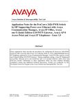
A full VRF solution commonly involves different portions of the IP networks being connected
to each other by an MPLS backbone network. The separate IP networks will be allocated
different tags in the MPLS network. So the full VRF solution involves not only managing
multiple separate IP networks within the same routers, but also a network-to-MPLS tag
mapping process.
In the full VRF solution a distinction is made between Customer Edge (CE) routers and
Provider Edge (PE) routers. CE routers aggregate the separate IP networks of the service
provider’s different clients. PE routers connect the IP networks to the MPLS backbone.
VPN 1
Customer A
VPN 1
Customer A
CE
PE
PE
CE
MPLS
network
MPLS-VRF
device
VPN 2
Customer B
MPLS-VRF
device
VPN 2
Customer B
CE = Customer edge device
PE = Provider edge router
VRF-lite is a subset of the full VRF solution. In a VRF-lite solution there are multiple IP
networks sharing the same routers, but no MPLS core is involved. So, VRF-lite is just the
customer edge router part of VRF, without the provider edge router part.
VRF-lite facilitates multiple separate routing tables within a single router - one routing table
associated with each of the customer VPNs connected to the device. Multiple VRF instances
are defined within a router. One or more Layer 3 interfaces (VLAN) are associated with each
VRF instance forming an isolated VRF routing domain. A Layer 3 interface cannot belong to
more than one VRF instance at any time.
Configure VRF-lite | Page 5
Understanding VRF-lite
VRF-lite security domains
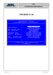
VRF-lite provides network isolation on a single device at Layer 3. Each VRF domain can use
the same or overlapping network addresses, as they have independent routing tables. This
separation of the routing tables prevents communication to Layer 3 interfaces in other VRF
domains on the same device. Each Layer 3 interface belongs to exactly one VRF instance and
traffic between two Layer 3 interfaces on the same VRF instance is allowed as normal. But by
default, interfaces in other VRF instances are not reachable as no route exits between the
interfaces unless explicitly configured via Inter-VRF routing.
vla
n1
vla
n2
PC1
Company A
10.
1.1
.1.1
1.1
.1/8
PC2
PC3
Company B
/24
SW
24
1.1/
6
1.1. .1.1/1
3
n
vla
vla 4 10.1
n5
1.1
vlan
vla
.1.1
n6
/24
10.
1.1
.1/2
4
PC4
PC5
VRF red
VRF green
VRF blue
Company C
PC6
For example, on a device three VRF instances (VRF red, VRF green and VRF blue) are
configured for three different companies. Devices PC1 and PC2 from Company A can
communicate normally within the confines of VRF red, but none of PC1’s and PC2’s traffic
can be seen by other devices in VRF green and VRF blue.
Route table and interface management with VRF-lite
A key feature that VRF-lite introduces to a router is the existence of multiple IP route tables
within the one router.
By default, before any VRF is configured, a router will have one route table, and routes via all
IP interfaces of the router will be stored in this one table. As VRF instances are configured on
the router, the original route table remains. This default route table, and its associated IP
interfaces, are then referred to as the default global VRF domain.
Interface management with VRF
Each network interface can belong to only one VRF. As mentioned above, initially every
interface is in the default global VRF domain. As Layer 3 interfaces are moved to the created
VRF instances, they are removed from the global VRF domain, so the global VRF domain
manages a decreasing set of Layer 3 interfaces.
Page 6 | Configure VRF-lite
Understanding VRF-lite
When a Layer 3 interface is moved to a VRF instance from the default global VRF domain, or
when a Layer 3 interface is moved from one VRF instance to another via command, the
interface name and id (ifindex) are never changed as a result of the interface movement.
However IP configuration on the interface in the previous VRF is unset (removed) before
moving the interface to a new VRF.
ARP entries associated with the Layer 3 interface are cleared when the interface is moved
from one VRF instance to another. In addition (static and dynamic) ARP entries are VRF
aware, as the same IP address can be used in other VRF instances.
Adding a VRF-aware static ARP
awplus(config)#arp ?
A.B.C.D IP address of the ARP entry
log
Arp log
vrf
VRF instance
awplus(config)#arp vrf <name> ?
A.B.C.D IP address of the ARP entry
Route management with VRF
Each VRF instance maintains its own IPv4 routing table independent from the routing table
of the global VRF domain or other VRFs.
Routing entries can be added statically by user command or dynamically by a routing
protocol module such as BGP, OSPF, or RIP within the VRF instance. Use of a dynamic
routing protocol allows for each VRF network to maintain a consistent routing table across
all the devices within the VRF network.
The way that each routing is able to define a separate instance of itself on multiple VRF
instances varies from protocol to protocol:
For BGP, one BGP routing instance will be running for an Autonomous System in the
global VRF domain and individual BGP routing tables will be managed per VRF by using
the address-family feature. One address-family is created for each VRF instance.
For OSPF, one OSPF routing instance is configurable per VRF, and one OSPF instance
is configurable within the global VRF domain.
For RIP, one RIP routing instance will be running in the default global VRF domain and
individual RIP routing tables will be managed per VRF by using the address-family
feature. One address-family is created for each VRF instance.
Note:
The command show ip route displays the routes associated with each VRF instance.
Configure VRF-lite | Page 7
Understanding VRF-lite
Inter-VRF communication
Whilst the prime purpose of VRF-lite is to keep routing domains separate from each other,
there are cases where you do want some communication between VRFs.
An example to consider is multiple 'clients' requiring shared Internet access. In this case a
VRF instance can be created for each, providing secure and separate routing. Whilst
overlapping IP addresses could be used with this scenario, only one instance of each
overlapping address range will be able to access the Internet for the simple reason that when
return traffic comes back from the Internet to an address in one of the overlapped subnets,
the VRF aware device must have only one choice for which instance of that subnet to send
that return traffic to.
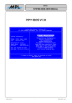
A distinct shared VRF is utilised to allow sharing of the Internet connection. The shared VRF
is actually just another VRF instance; it has no special VRF properties.
In the example below, each of the red and green VRFs need inter-VRF communication with
the shared VRF. This is achieved by selectively leaking routes between the shared VRF and
the other two VRFs, and vice-versa. The selective leaking can use statically configured routes
or dynamic route import/export via the BGP protocol.
Internet
F
d
re
a
sh
n
e )
re y
g an
F p
R
V om
(c
ess
acc
R
V
d
re i)
F F
R iV W
(
-Fi
Wi
Internal Company
Network
For example, a company may wish to segregate their network and provide Wi-Fi access to
the Internet for visitors to the company, whilst preventing the visitors from accessing the
internal company network. The users in internal company network and visitors in the Wi-Fi
network are able to share a single common Internet connection.
Internal company and Wi-Fi networks are isolated in Layer 3 on the same device by using
different VRFs, but they want to access the Internet by using the same network interface on
VRF shared. To make it work with dynamic route import/export, VRF green (company VRF)
needs to import routes from VRF shared to access the Internet and some selected routes
from VRF green need to be exported to VRF shared. Similar configuration is needed for VRF
red (Wi-Fi VRF) for importing/exporting routes between VRF red and VRF shared.
As a result traffic flows between VRF green and VRF shared and between VRF red and VRF
shared but not between VRF green and VRF red.
Page 8 | Configure VRF-lite
Understanding VRF-lite
Static and dynamic inter-VRF routing
As mentioned above, "Inter-VRF communication" on page 8, in some circumstances it is
required to (selectively) allow traffic between two interfaces that are not in the same VRF.
This will be useful if there is common network equipment (e.g. Internet connections or
shared resources) that multiple VRFs need to share.
Inter-VRF routing is achieved by statically or dynamically taking a route entry and its next-hop
interface from one VRF, and adding it into the routing table of another. A dynamic inter-VRF
route can be added by using the BGP route import/export feature. A static inter-VRF route
can be added by a user command. For more information on static routing, see "Static interVRF routing" on page 17.
Static and dynamic inter-VRF communication can be used simultaneously or separately.
Dynamic inter-VRF communication is only achieved via use of the BGP routing protocol.
OSPF and RIP cannot be used to achieve inter-VRF communication.
Internally transferring routes between VRF instances is quite separate from the sharing of
routes of a specific VRF routing domain, with external routers that are members of that same
domain. As mentioned above, all dynamic routing protocols can be used to distribute routing
information to external peer devices. OSPF, RIP, and BGP can all be used to dynamically
distribute routes to external peers within VRF routing domains.
When BGP is used for dynamic inter-VRF communication, routes from other routing
protocols (including connected routes, static routes, OSPF or RIP) are redistributed into a
VRF instance’s BGP route table (BGP must be configured and associated with the VRF
instance). Other VRF instances that are configured with BGP can selectively copy these
routes into their own separate BGP route tables.
Inter-VRF route leakage interoperates with the exchange of route information. Routes learnt
from external peers in one VRF domain can be leaked to other VRF instances and routes
leaked into a VRF instance can then be advertised to external peers connected to that
instance.
The details of dynamic inter-VRF routing are described in "Dynamic inter-VRF communication
explained" on page 18.
Configure VRF-lite | Page 9
Understanding VRF-lite
VRF-lite features in AW+
Here is a summary of the features provided by the AW+ VRF-lite implementation:
Multiple independent routing table instances may co-exist within the same device. The
same or overlapping IP addresses can be present in different route table instances without
conflicting. All routing table instances remain securely isolated from those existing in other
routing tables.
By default, no communication occurs between VRF instances, facilitating multiple secure
routing domains within the same VRF aware device.
However, inter-VRF communication between routing domains is possible by using either
static inter-VRF routes and/or dynamic filtered route leakage via BGP and its associated
route maps.
A single device configuration file simplifies management by providing the ability to create,
manage, and monitor all VRF instances.
Detailed diagnostic and debugging information is available.
Ability to view routing table information per VRF.
All appropriate VRF related information and error messages can be viewed in the
system wide log.
Separate instances of routing protocols can be mapped to VRF instances so that
distribution of route information can be performed on a per VRF domain basis. This
enables route information to be distributed securely within each VRF routing domain.
For example:
VRF1 = OSPF routing instance1
VRF2 = OSPF routing instance2
All Layer 3 interfaces and associated switch ports remain in the default global VRF domain
until associated with a specific VRF instance.
VRF is supported in HW and SW (including Inter-VRF communications).
The default global VRF domain always exists and cannot be removed. Initially during
startup, every VLAN belongs to the default global VRF domain. Also, when a VLAN is
removed from a VRF, it is automatically returned to the default global VRF domain. Only
one default global VRF domain exists in each physical device.
Static and dynamic routes can be leaked from a VRF instance to the global default VRF.
Selected routes within a VRF instance can be dynamically leaked to other VRF routing
domains. This applies both to routes that have been statically configured, and to routes
that have been learnt into a VRF instance on the device by routing protocol exchanges
with external peer routers.
When a VRF instance has received routes leaked from other VRF instances, that instance
can advertise those routes to external peer routers connected to interfaces in that VRF
instance, via the routing protocol operating within the VRF instance.
Page 10 | Configure VRF-lite
Understanding VRF-lite
Route limiting per VRF instance
In a multi-VRF network environment, it may be problematic if one VRF injects too many
routes and fills up the hardware forwarding table (FIB) on the device, which can affect other
VRFs as well as the global VRF. For more information see "Route Limits" on page 84
VRF-aware utilities within AW+
Some network utility and management features such as ping, traceroute, telnet client, SSH
client, and tcpdump are supported in a VRF aware manner.
VRF aware services include
Ping
awplus#ping ?
WORD Ping destination address or hostname
ip
IP echo
ipv6 IPv6 echo
vrf
VRF instance (source VRF)
<cr>
awplus#ping vrf <name> ?
WORD Ping destination address or hostname
ip
IP echo
awplus#ping vrf <name> x.x.x.x
awplus#ping vrf <name> x.x.x.x ?
broadcast Ping to a broadcast address
df-bit
Enable do-not-fragment bit in IP header
interval
Specify interval between pings
pattern
Specify data pattern
repeat
Specify repeat count
size
Specify datagram size
source
Specify source address or interface name
timeout
Specify timeout interval
tos
Specify type of service
<cr>
Trace route
awplus#traceroute ?
WORD Trace route to destination address or hostname
ip
IP Trace
ipv6 IPv6 trace
vrf
VRF instance
<cr>
awplus#traceroute vrf <name> ?
WORD Trace route to destination address or hostname
ip
IP Trace
awplus#traceroute vrf <name> x.x.x.x
Configure VRF-lite | Page 11
Understanding VRF-lite
Telnet client
awplus#telnet ?
WORD IPv4/IPv6 address or hostname of a remote system
ip
IP telnet
ipv6 IPv6 telnet
vrf
VRF instance
awplus#telnet vrf <name> ?
WORD IPv4 address or hostname of a remote system
ip
IP telnet
awplus#telnet vrf <name> ip x.x.x.x
SSH client
awplus#ssh ?
HOSTNAME IP/IPv6 address or hostname of a remote server
client
Configure global SSH client parameters
ip
IP SSH
ipv6
IPv6 SSH
port
SSH server port
user
Login user
version
SSH client version
vrf
VRF instance
awplus#ssh vrf <name> ?
HOSTNAME IP/IPv6 address or hostname of a remote server
ip
IP SSH
port
SSH server port
user
Login user
version
SSH client version
awplus#ssh vrf <name> x.x.x.x
TCP dump
awplus#tcpdump ?
LINE Execute tcpdump
vrf
VRF instance
<cr>
awplus#tcpdump vrf <name> ?
LINE Execute tcpdump
<cr>
awplus#tcpdump vrf <name>
In this VRF-lite implementation, other Layer 4+ services and applications are not supported
on a per-VRF basis - such as Telnet server, SSH server, file copy, system log, SNMP server,
DHCP server, DHCP relay, NTP server, etc. However, these services will remain supported
in the global VRF domain context, which is same as in a non-VRF environment.
Page 12 | Configure VRF-lite
Configuring VRF-lite
Configuring VRF-lite
The following section describes the generic commands used to configure VRF-lite.
CONFIGURING ACLS
PURPOSE
Step 1
awplus# conf t
Enter Global Configuration mode.
Step 2
awplus(config)# access-list standard
<access-list-name> {deny|
permit}<network>
Optional. This command configures a standard
named access-control-list (ACL). Matching
networks (routes) are either imported to or
exported from a VRF instance to BGP.
Alternatively, matching networks are denied
from being imported to or exported from a
VRF instance to BGP. This command is
optionally used in the context of VRF when
using BGP to facilitate inter-VRF
communications. These optional ACLs should
be configured before any inter-VRF
communication is configured, to prevent
unnecessary routes from being leaked from one
VRF to another.
CONFIGURING VRFS
PURPOSE
Step 1
awplus(config)#ip vrf <vrf-name> <lointerface-number>
Create a named Virtual Router Forwarding
(VRF) instance. If the optional Local Interface
(LO) parameter not specified, a local interface is
automatically created and associated with the
VRF instance. If the LO parameter is specified, it
allows the user to control which LO is
associated with a particular VRF instance.
Step 2
awplus(config-vrf)#rd <route
distinguisher>
Optional. Create a route distinguisher (rd) in
the form of an ASN, which also references a
specific VRF instance. Format is in the form
ASN:VRF instance. This command is required if
using BGP to facilitate inter-VRF communication.
Step 3
awplus(config-vrf)#route-target export
<ASN>
Optional. Exports routes from the VRF instance
to BGP.
Step 4
awplus(config-vrf)#route-target import
<ASN>
Optional. Imports routes from BGP into the
VRF instance.
Step 5
awplus(config-vrf)#import map <routemap-name>
Optional. Configure an import map, which
references a route map, and associated ACL.
Used to selectively import routes into the VRF
instance from BGP.
Step 6
awplus(config-vrf)#export map <routemap-name>
Optional. Configure an export map, which
references a route map, and associated ACL.
Used to selectively export routes from the VRF
instance to BGP.
Step 7
awplus(config-vrf)#exit
Return to Global Configuration mode.
Configure VRF-lite | Page 13
Configuring VRF-lite
CONFIGURING VLANS AND VLAN DATABASE
PURPOSE
Step 1
awplus(config)#vlan database
VLANs are created in the VLAN database, and
ports are assigned to relevant VLANs.
Step 2
awplus(config-vlan)#vlan x state enable
Step 3
awplus(config-vlan)#exit
Step 4
awplus(config)#interface portx.x.x
Step 5
awplus(config-if)#switchport access vlanx
Step 6
awplus(config-if)#exit
CONFIGURING LOCAL LOOPBACK IP INTERFACE
Step 1
awplus(config-if)#interface lo1
Step 2
awplus(config-if)#ip address x.x.x.x/x
Step 3
awplus(config-if)#exit
PURPOSE
Optional - IP network is associated with the LO
interface, to be used by upper layer routing
protocols.
CONFIGURING VLANS - IP AND VRF MEMBERSHIP
PURPOSE
Step 1
awplus(config)#interface <vlan-name>
VRF routing domains are formed by associating
a VLAN Layer 3 interface with a VRF instance.
Step 2
awplus(config-if)#ip vrf forwarding <vrf- <name>is the name of a VRF instance created
name>
by the IP VRF <name> command.
Step 3
awplus(config-if)#ip address <subnet>
Step 4
awplus(config-if)#exit
DYNAMIC ROUTING PROTOCOL - OSPF INSTANCE
PURPOSE
Step 1
awplus(config)#router osfp <1-65535>
<vrf-name>
Optional. Associate an OSPF routing instance
with a specific VRF instance, and enter router
configuration mode.
Step 2
awplus(config-router)#network <x.x.x.x/
x> area <area-id>
Define a network on which the OSPF instance
runs and the area ID for that network.
Step 3
awplus(config-router)#redistribute
<protocol>
Configure the device to redistribute information
from another routing protocol into OSPF. For
example BGP can be specified, to allow OSPF
to advertise inter-VRF routes to an OSPF peer.
Step 4
awplus(config-router)#exit
Page 14 | Configure VRF-lite
Configuring VRF-lite
DYNAMIC ROUTING PROTOCOL - RIP ADDRESS-FAMILY
PURPOSE
Step 1
awplus(config)#router rip
Optional. Enter router configuration mode for
RIP.
Step 2
awplus(config-router)#address-family
ipv4 vrf <vrf-name>
Associate a RIP address-family with a specific
VRF instance.
Step 3
awplus(config-router-af)#network
x.x.x.x/x
Define a network on which the RIP addressfamily runs.
Step 4
awplus(config-router-af)#redistribute
<protocol>
Configure the device to redistribute information
from another routing protocol into the RIP
address-family. For example BGP can be
specified, to allow RIP to advertise inter-VRF
routes to a RIP neighbor.
Step 5
awplus(config-router)#exit-addressfamily
Step 6
awplus(config-router)#exit
DYNAMIC ROUTING PROTOCOL - BGP ADDRESS-FAMILY
PURPOSE
Step 1
awplus(config)#router bgp <ASN>
Mandatory if BGP is used for inter-VRF
communications. Not required if static interVRF routes are used instead of BGP to provide
inter-VRF communications. Enter router
configuration mode for BGP and assign the BGP
ASN. Define a single BGP ASN for the device.
Multiple ASNs not supported.
Step 2
awplus(config-router)#address-family
ipv4 vrf <vrf-name>
Associate a BGP address-family with a specific
VRF instance.
Step 3
awplus(config-router-af)#redistribute
<protocol>
Configure the device to redistribute information
from another routing protocol into the BGP
address-family. For example 1) connected, or
static can be specified, to allow BGP to
advertise connected or static routes to BGP
neighbor - if external BGP neighbor is
configured. 2) Ensure the connected or static
routes are redistributed into BGP to be used for
inter-VRF communications.
Step 4
awplus(config-router-af)#neighbor
x.x.x.x <remote-ASN>
If required, define a BGP neighbor and its
associated ASN.
Step 5
awplus(config-router-af)#neighbor
x.x.x.x activate
Activate the BGP neighbor to allow the BGP
Transport Layer TCP connection to establish to
the specified BGP neighbor.
Step 6
awplus(config-router-af)#exit-addressfamily
Step 7
awplus(config-router)#exit
Configure VRF-lite | Page 15
Configuring VRF-lite
STATIC ROUTES
PURPOSE
Step 1
Optional. To add a static route into the Routing
table for a VRF instance. This can be a route
pointing externally to a nexthop reachable via
an interface in this VRF instance, or it can be
used to facilitate inter-VRF routing, in which
case it would point to an interface in a different
VRF instance. Static inter-VRF routes can be
used instead of BGP, or in conjunction with BGP
to provide inter-VRF communications.
awplus(config)# ip route vrf <name>
<network> {<gateway> <interface>|
<interface>}
ROUTE MAPS THAT REFERENCE ACLS AND VRFS
PURPOSE
Step 1
awplus(config)#route-map word (deny|
permit) <1-65535>
Optional. Configure a route map name that is
referenced by a VRF import or export map.
Step 2
awplus(config-route-map)#match ip
address <ACL name>
Configure a route map entry which references
an ACL.
Step 3
awplus(config-route-map)#exit
Step 4
awplus(config)#exit
Page 16 | Configure VRF-lite
Configuring VRF-lite
Static inter-VRF routing
Static inter-VRF routing involves creating static routes in one VRF instance whose egress
VLAN is in a different egress VLAN. These static routes must specify both the egress VLAN
and next hop IP address.
The following diagram illustrates use of static routing to achieve inter- VRF communication in
VRF-lite.
1 9 2 .1 6 8 .1 .0/2 4
VRF red
192.168.1.5
VLAN20
1 9 2 .1 6 8 .2 0 .0/2 4
global default VRF domain
VLAN10
1 9 2 .1 6 8 .2 0 .0/2 4
VRF green
192.168.20.6
192.168.20.5
Device A
VLAN10
1 9 2 .1 6 8 .5 0 .0/2 4
VRF blue
VLAN30
192.168.50.10
Device B
DEVICE A STATIC ROUTES CONFIGURATION
DEVICE B STATIC ROUTES CONFIGURATION
ip route vrf red 192.168.20.0/24 vlan10
ip route vrf blue 192.168.20.0/24 vlan10
From source vrf red, create a static route to
From source vrf blue, create a static route to 192.168.20.0/24
192.168.20.0/24 to access target vlan10. Target vlan is
required when performing static IVR.
to access target vlan10. Target vlan is required when
performing static IVR.
ip route 192.168.1.0/24 vlan20
ip route vrf green 192.168.50.0/24 vlan30
From the source global VRF domain, create a static route to From the source vrf green, create a static route to
192.168.50.0/24 to access target vlan30. Target vlan is required
192.168.1.0/24 to access target vlan20. Target vlan is
when performing static IVR.
required when performing static IVR.
ip route vrf red 192.168.50.0/24 192.168.20.6 vlan10 ip route vrf blue 192.168.1.0/24 192.168.20.5 vlan10
From source vrf red, create a static route to
192.168.50.0/24 with a next hop of 192.168.20.6
From source vrf blue, create a static route to 192.168.1.0/24
with a next hop of 192.168.20.5 egressing target vlan10.
egressing target vlan10. Target vlan is required when
performing static IVR.
Target vlan is required when performing static IVR.
ip route 192.168.50.0/24 192.168.20.6
ip route vrf green 192.168.1.0/24 192.168.20.5
From the global VRF domain, create a static route to
From the source vrf green, create a static route to 192.168.1.0/
24 with a next hop of 192.168.20.5. Static routes to networks
within a VRF instance do not require the target vlan.
192.168.50.0/24 with a next hop of 192.168.20.6.
Static routes to networks within a VRF instance do
not require target vlan.
Configure VRF-lite | Page 17
Dynamic inter-VRF communication explained
Dynamic inter-VRF communication explained
The following section explains how VRF routing domain isolation is maintained, and how
routes that exist in one VRF instance are leaked to another VRF instance via BGP. Only BGP
can be used to dynamically leak routes from one VRF instance to another.
The Forwarding Information Base (FIB) and routing protocols
Associated with each VRF instance is an IP route table, also known as the Forwarding
Information Base (FIB). When BGP address-families (associated with VRF instances) are
configured, a corresponding BGP route table is created for each VRF instance on which a
BGP address-family is configured.
Similarly, when RIP address-families (associated with VRF instances) are configured, a
corresponding RIP route table is created for each VRF instance on which a RIP address-family
is configured.
Similarly, when OSPF instances (associated with VRF instances) are configured, a
corresponding OSPF route table is created for each VRF instance on which an OSPF instance
is configured.
Each dynamic routing protocol automatically selects appropriate routes and copies them to
the FIB.
Static and connected routes are automatically added to the FIB when they are created.
OS
PF
1
ad R
fa dre IP
re mily ssd
F
F
R
V d
re IB
ad BG
fa dre P
re mily ssd
ad BG
fa dre P
bl mil ssue y
F
R
V lue
b IB
F
BGP routes copied between BGP
address-families to facilitate inter-VRF
communication
Page 18 | Configure VRF-lite
ad R
fa dre IP
bl mil ssue y
OS
PF
2
VRF Device
Dynamic inter-VRF communication explained
The command redistribute <protocol> can be configured in an OSPF instance, BGP
address-family, or RIP address-family. Via this command, routes are imported from the FIB
associated with the VRF instance into the dynamic routing protocol table. Any routing
protocol (OSPF, BGP, RIP static, connected, etc.) can be redistributed.
Dual role of
BGP
For example, if OSPF instance1 is configured on VRF red, and if OSPF 1 contains the
command redistribute BGP, then BGP routes will be copied from VRF red FIB to OSPF
instance1.
Similarly, if BGP address-family is configured on VRF red, and if the address-family contains
the command redistribute OSPF, then OSPF instance1 routes will be copied from the
VRF red FIB into the BGP red address-family route table.
The first role that BGP plays in a VRF-lite environment is to facilitate BGP peering to an
external router operating within the VRF routing domain via the neighbor x.x.x.x command
configured in a BGP address-family.
The second role that BGP plays is to facilitate route leakage between VRF routing domains.
Dynamic routing protocols (RIP and OSPF) do not facilitate route leakage. RIP and OSPF
only operate within a VRF routing domain.
Configure VRF-lite | Page 19
Dynamic inter-VRF communication explained
Inter-VRF communication via BGP
Dynamic inter-VRF route leakage is achieved by making copies of BGP routes that exist in
one BGP address-family associated with one VRF instance, to another BGP address-family
associated with a different VRF instance.
r
e
e
p r
P e
F t
S u
O ro
OS
PF
Redistribute BGP
from VRF red FIB
1
V
r RF
FI ed
B
Redistribute OSPF
from VRF red FIB
Redistribute BGP
from VRF blue FIB
ad BG
fa dre P
re mily ssd
V
b RF
FI lue
B
ad BG
fa dre P
bl mil ssue y
OS
PF
2
r
e
e
p r
P e
F t
S u
O ro
Redistribute OSPF
from VRF blue FIB
BGP routes copied between BGP
address-families to facilitate inter-VRF
communication
VRF Device
In the diagram above, the following is configured:
OSPF1 is configured in VRF-red, and OSPF1 contains redistribute BGP
OSPF2 is configured in VRF-blue, and OSPF2 contains redistribute BGP
BGP is configured and contains BGP address-families red and blue
Both BGP address-families contain redistribute OSPF
Then route leakage of routes from VRF red to VRF blue occurs as follows:
1. OSPF1 selects appropriate OSPF routes learned from external VRF red OSPF peer and
automatically adds them to red FIB route table.
2. OSPF1 routes are imported from red FIB route table into BGP address-family red BGP
route table (via the BGP redistribute OSPF command).
3. Via the route-target import command, BGP address-family red BGP routes are selected
and copied into BGP address-family blue BGP route table.
4. Appropriate BGP address-family blue BGP routes are selected and automatically added to
the VRF blue FIB route table.
5. OSPF2 then imports and redistributes the BGP routes (learned originally from VRF red
OSPF peer) into OSPF2 from VRF blue FIB route table (via OSPF redistribute BGP
command).
6. Those OSPF routes are then advertised to external VRF blue OSPF peer.
And the same process is used to leak routes from VRF blue to VRF red.
Page 20 | Configure VRF-lite
Dynamic inter-VRF communication explained
Using the route-target command
When BGP is used for inter-VRF communication, dynamic route leakage of BGP routes from
one VRF instance to another is achieved via the VRF route-target command.
There are three variations of the route-target command:
1. route-target export <ASN:VRFinstance>
for example:
ip vrf red
rd 100:1
route-target export 100:1
2. route-target import <ASN:VRFinstance>
for example:
ip vrf red
rd 100:1
route-target import 100:2
3. route-target both <ASN:VRFinstance>*
for example:
ip vrf red
rd 100:1
route-target
route-target
route-target
route-target
export
export
export
import
100:1
100:2
100:3
100:2
can be replaced with:
ip vrf red
rd 100:1
route-target export 100:1
route-target export 100:3
route-target both 100:2
*Use of the command route-target both is uncommon in a VRF-lite environment.
The command route-target export applies a BGP extended community attribute to each
BGP prefix stored in the BGP route table of the address-family associated with the VRF
instance. The content of this attribute is the (ASN) that was specified in the route-target
export command.
Configure VRF-lite | Page 21
Dynamic inter-VRF communication explained
The following three examples demonstrate how the route-target command facilitates interVRF communication:
1.
If VRF red configuration includes:
ip vrf red
rd 100:1
route-target export 100:1
And if VRF red initially has routes to networks 10.0.0.0/24, 20.0.0.0/24, then the entries in the
address-family red BGP route table for each of those two routes would have the extendedcommunity attribute applied as follows:
10.0.0.0/24 100:1
20.0.0.0/24 100:1
Also, if VRF shared configuration includes:
ip vrf shared
rd 100:2
route-target import 100:1
then VRF shared will check all other VRFs’ BGP tables searching for routes with the
extended-community attribute 100:1, and those specific routes will be copied into the VRF
shared BGP route table from the other VRFs, and they will be marked as copied BGP routes.
VRF shared will then have copied BGP routes that have been leaked from VRF red:
(copy)10.0.0.0/24 100:1
(copy)20.0.0.0/24 100:1
2. If VRF red initially includes:
ip vrf red
rd 100:1
route-target export 100:1
route-target import 100:2
10.0.0.0/24 100:1
20.0.0.0/24 100:1
And if VRF shared initially includes:
ip vrf shared
rd 100:2
route-target export 100:2
route-target import 100:1
30.0.0.0/24 100:2
40.0.0.0/24 100:2
Then via BGP inter-VRF routing (IVR), VRF red will end up with the routes:
10.0.0.0/24 100:1
20.0.0.0/24 100:1
(copy)30.0.0.0/24 100:2
(copy)40.0.0.0/24 100:2
And via BGP IVR, VRF shared will end up with the routes:
(copy)10.0.0.0/24 100:1
(copy)20.0.0.0/24 100:1
30.0.0.0/24 100:2
40.0.0.0/24 100:2
Each VRF instance now contains dynamic inter-VRF routes.
Page 22 | Configure VRF-lite
Dynamic inter-VRF communication explained
3. If VRF red configuration includes*:
ip vrf red
rd 100:1
route-target
route-target
route-target
route-target
route-target
route-target
export
export
export
export
import
import
100:1
100:2
100:3
100:4
100:5
100:6
And if VRF red initially has routes to networks 10.0.0.0/24, 20.0.0.0/24, then each of those
two routes would have multiple extended community attributes (as defined in the routetarget export command configured in the VRF instance) as follows:
10.0.0.0/24 100:1 100:2 100:3 100:4
20.0.0.0/24 100:1 100:2 100:3 100:4
And If VRF shared configuration includes:
ip vrf shared
rd 100:5
route-target export 100:5
route-target import 100:2
And if VRF shared initially has routes to networks 30.0.0.0/24, 40.0.0.0/24, then each of those
two routes would have an extended community attribute applied (as defined in the routetarget export command) as follows:
30.0.0.0/24 100:5
40.0.0.0/24 100:5
Then via BGP IVR, VRF red will end up with the routes:
10.0.0.0/24 100:1
20.0.0.0/24 100:1
(copy)30.0.0.0/24
(copy)40.0.0.0/24
100:2 100:3 100:4
100:2 100:3 100:4
100:5
100:5
And via BGP IVR, VRF shared will end up with the routes:
(copy)10.0.0.0/24 100:1 100:2 100:3 100:4
(copy)20.0.0.0/24 100:1 100:2 100:3 100:4
30.0.0.0/24 100:5
40.0.0.0/24 100:5
*Use of the command route-target export, as per example 3 above, to tag routes in a VRF
instance with ASNs associated with other VRF instances is uncommon in a VRF-lite
environment.
Configure VRF-lite | Page 23
Dynamic inter-VRF communication explained
How VRF-lite security is maintained
Incidentally, only the original routes can be copied from one VRF to another. Copied routes
cannot be subsequently copied to another VRF, to ensure VRF security domains are
enforced.
For example:
VRFred----VRFshared----VRFgreen
If VRF red routes are copied into the route table of VRF shared, VRF red routes will not be
able to subsequently be copied from VRF shared into the VRF green route table. This
ensures that while VRF green, and VRF red can access VRF shared, there is no inter-VRF
communication between VRF red and VRF green - unless additional route leakage is
configured.
Similarly, routes learnt by the default global VRF domain from a VRF instance via internal BGP
peering cannot be subsequently advertised from the default global VRF domain to another
VRF instance.
VRFred---default_global_VRF---VRFgreen
Viewing source VRF and attribute information for a prefix
The command show ip bgp < prefix> can be used to display source VRF and extended
community attribute information for a route.
For example:
VRF_device#show ip bgp 192.168.120.0
[VRF: green]
BGP routing table entry for 192.168.120.0/24
Paths: (1 available, best #1, table Default-IP-Routing-Table)
Not advertised to any peer
192.168.20.1 from 192.168.20.10 (192.168.20.10)
Origin IGP metric 0, localpref 100, valid, external, best
Extended Community: RT:500:2
Last update: Thu Nov 18 03:51:06 2010
[VRF: common]
BGP routing table entry for 192.168.120.0/24
Paths: (1 available, best #1, table Default-IP-Routing-Table)
Not advertised to any peer
192.168.20.1 from 192.168.20.10 (192.168.20.10)
Origin IGP metric 0, localpref 100, valid, external, best
Extended Community: RT:500:2
Copied from VRF: green
Last update: Thu Nov 18 03:51:06 2010
Page 24 | Configure VRF-lite
Simple VRF-lite configuration examples
Simple VRF-lite configuration examples
The following section contains simple configuration examples to explain the basics of VRF-lite
configuration used in conjunction with a variety of routing protocols.
Firstly, always create a clear VRF communication plan. This includes researching the various
routing protocols and likely IP network plans for each VRF, and the likely content of each VRF
routing table. Also confirm any overlapping IP address space requirements, and if there are
any inter-VRF communication requirements.
Multiple VRFs without inter-VRF communication
The partial configuration example below shows the key components required to support
multiple VRF instances with OSPF peering to external neighbors within each VRF instance.
There is no inter-VRF communication used in this first example.
Two interfaces, vlan11 and vlan12 are configured for Customer1 (VRF red), and two other
interfaces, vlan13 and vlan14 are configured for Customer2 (VRF green). In this example,
overlapping IP addresses are used. OSPF is used as the routing protocol within each VRF
instance.
PC3
PC4
R3
vlan
VRF
R1
13
4
R4
1
vlan
n 11
vla
vlan
12
Customer2 (VRF green)
R2
PC1
PC2
Customer1 (VRF red)
...
!
ip vrf red
description Customer1
!
ip vrf green
description Customer2
!
interface vlan11
ip vrf forwarding red
ip address 10.1.1.1/24
[cont...]
Configure VRF-lite | Page 25
Simple VRF-lite configuration examples
!
interface vlan12
ip vrf forwarding red
ip address 10.2.2.1/24
!
interface vlan13
ip vrf forwarding green
ip address 10.1.1.1/24
!
interface vlan14
ip vrf forwarding green
ip address 10.2.2.1/16
!
router ospf 1 red
network 10.1.1.0/24 area
network 10.2.2.0/24 area
redistribute connected
!
router ospf 2 green
network 10.1.1.0/24 area
network 10.2.0.0/16 area
redistribute connected
!
...
Page 26 | Configure VRF-lite
0
0
0
0
Simple VRF-lite configuration examples
VRFs accessing a shared network. An example of static inter-VRF routing
The partial configuration example below shows the key components required to support
static inter-VRF routing.
Two companies (VRF red and VRF green) are able to access shared vlan100. Shared vlan100
exists in the Global default VRF. Static inter-VRF routing is used in this example to facilitate
inter-VRF communication. There are no overlapping IP addresses. As there is no external
router in vlan100 and there is no Internet access via vlan100, ACLs are not required.
vla
n1
2
0.1
.0/2
4
1.1
lt
u
fa n
e i
d a
l
a m
b do
lo F
G R
V
00 24
/
n1
vla 100.0
.
0
0
1
.
0
10
F
R
V
d
re
F
R
V
n
e
re
g
1.2vlan 1
0.1 4
.0/2
4
- Inter VRF (IVR) communications
via static IVR routes
...
!
ip vrf red
!
ip vrf green
!
interface vlan12
ip vrf forwarding red
ip address 1.10.1.1/24
!
interface vlan14
ip vrf forwarding green
ip address 1.20.1.1/24
!
interface vlan100
ip address 100.100.100.100/24
!
ip route vrf red 0.0.0.0/0 vlan100
ip route vrf green 0.0.0.0/0 vlan100
ip route 1.10.1.0/24 vlan12
ip route 1.20.1.0/24 vlan14
!
...
Configure VRF-lite | Page 27
Simple VRF-lite configuration examples
Dynamic inter-VRF communication with RIP routing to
external peers
The partial configuration example below shows the key components required to support
dynamic inter-VRF communication between two VRF instances using BGP, with RIP routing to
external peers.
RIP address-families are created, and each RIP address-family is associated with a VRF
instance. To achieve inter-VRF communications, BGP is redistributed into each RIP family.
Conversely, BGP address-families are created and each BGP address-family is associated with
a VRF instance, and RIP is redistributed into each BGP address-family. Connected routes are
also redistributed into BGP to be leaked between VRF instances.
...
!
ip vrf red
rd 100:1
route-target export 100:1
route-target import 100:2
!
ip vrf green
rd 100:2
route-target export 100:2
route-target import 100:1
!
router rip
!
address-family ipv4 vrf red
network vlan20
redistribute bgp
exit-address-family
!
address-family ipv4 vrf green
network vlan60
redistribute bgp
exit-address-family
!
router bgp 100
address-family ipv4 vrf red
redistribute connected
redistribute rip
exit-address-family
!
address-family ipv4 vrf green
redistribute connected
redistribute rip
exit-address-family
!
...
Page 28 | Configure VRF-lite
Simple VRF-lite configuration examples
Dynamic inter-VRF communication with BGP routing to
external peers
The partial configuration example below shows the key components required to support
dynamic inter-VRF communication using BGP, with BGP routing to external peers.
BGP address-families are created. Each BGP address-family is associated with a VRF instance.
Routes within the VRF domain are advertised to external BGP peers. Selected BGP routes
(including connected routes redistributed into BGP, and BGP routes learned from external
BGP neighbors) are copied between VRF instances.
...
!
ip vrf red
rd 100:1
route-target export 100:1
route-target import 100:2
!
ip vrf green
rd 100:2
route-target export 100:2
route-target import 100:1
!
router bgp 100
!
address-family ipv4 vrf red
redistribute connected
neighbor 1.1.1.1 remote-as 100
neighbor 1.1.1.1 activate
exit-address-family
!
address-family ipv4 vrf green
neighbor 2.2.2.2 remote-as 200
neighbor 2.2.2.2 activate
redistribute connected
exit-address-family
!
...
Configure VRF-lite | Page 29
Simple VRF-lite configuration examples
Dynamic inter-VRF communication with OSPF routing to
external peers
The complete configuration example below shows the key components required to support
dynamic inter-VRF communication using BGP, with OSPF routing to external peers.
VRFs red, green and shared are configured. VRFs red and green can access VRF shared, but
not each other. OSPF routing is used in VRFs red and green, and these routes are leaked into
VRF shared via BGP. The connected routes in VRFs red, green and shared are also
redistributed into BGP to be leaked between VRF instances.
There are also three static routes configured in VRF shared to access shared router
networks. ACLs and associated route maps and VRF import maps are used to selectively leak
routes from VRF shared to VRFs red and green. For example, VRF red will selectively learn
routes to VRF shared networks 192.168.30.0/24 and 192.168.33.0/24, and VRF green will
selectively learn routes to VRF shared networks192.168.30.0/24 and 192.168.35.0/24.
192
.16
8.3
5.0
/24
d
re r
a te
sh u
ro
d
re
a
sh :3
F 0
R 10
V
n3
24
vla 30.0/
68.
1
.
92
d
re
F :1
R 0
V 10
1
192
.16
8.3
3.0
/24
n
e
re
g 2
F 0:
R 0
V 1
d r
re te
u
ro
n1
vla
PF1 24
OS 10.0/
.
168
.
2
19
4
0/2
34.
68.
.1
192
n
e r
re e
g ut
ro
n2
vla 2
PF 24
OS 20.0/
68.
2.1
19
- Inter VRF (IVR) communications
via Route leakage
Page 30 | Configure VRF-lite
Simple VRF-lite configuration examples
!
access-list standard greenBlock3334 deny 192.168.33.0/24
access-list standard greenBlock3334 deny 192.168.34.0/24
access-list standard greenBlock3334 permit any
access-list standard redBlock3435 deny 192.168.34.0/24
access-list standard redBlock3435 deny 192.168.35.0/24
access-list standard redBlock3435 permit any
!
ip vrf red
rd 100:1
route-target export 100:1
route-target import 100:3
import map red33
!
ip vrf green
rd 100:2
route-target export 100:2
route-target import 100:3
import map green35
!
ip vrf shared
rd 100:3
route-target import 100:1
route-target import 100:2
route-target export 100:3
!
vlan database
vlan 2-3 state enable
!
interface port1.0.1
switchport
switchport mode access
!
interface port1.0.2
switchport
switchport mode access
switchport access vlan 2
!
interface port1.0.3
switchport
switchport mode access
switchport access vlan 3
!
interface port1.0.4-1.0.26
switchport
switchport mode access
!
[cont...]
Configure VRF-lite | Page 31
Simple VRF-lite configuration examples
interface vlan1
ip vrf forwarding red
ip address 192.168.10.1/24
!
interface vlan2
ip vrf forwarding green
ip address 192.168.20.1/24
!
interface vlan3
ip vrf forwarding shared
ip address 192.168.30.1/24
!
router ospf 1 red
network 192.168.10.0/24 area 0
redistribute bgp
!
router ospf 2 green
network 192.168.20.0/24 area 0
redistribute bgp
!
router bgp 100
address-family ipv4 vrf red
redistribute ospf
redistribute connected
exit-address-family
!
address-family ipv4 vrf green
redistribute ospf
redistribute connected
exit-address-family
!
address-family ipv4 vrf shared
redistribute static
redistribute connected
exit-address-family
!
ip route vrf shared 192.168.33.0/24 192.168.30.3
ip route vrf shared 192.168.34.0/24 192.168.30.3
ip route vrf shared 192.168.35.0/24 192.168.30.3
!
route-map red33 permit 1
match ip address redBlock3435
!
route-map green35 permit 1
match ip address greenBlock3334
!
line con 0
line vty 0 4
!
end
Page 32 | Configure VRF-lite
Inter-VRF configuration examples with Internet access
Inter-VRF configuration examples with Internet
access
The following three complete examples are using a similar topology, however, each example
involves a different communication plan and a variety of routing protocols. All of the
following examples utilise one or more Internet connections.
Example A
Internet
Intranet
remote1
ute
4
F
R e4 0
V fic 20
a
of N 4_
A
L ce
V offi
3
F
R d3 0
V are 10 a
sh N 3_ 1
A d 0
L re 1 b
V ha N 3_ 2
s A d
2
F 2
L re 10 c
R te 0
V ha N 3_
V o 2
s
ed
A
m N _a
L ar
re A te2 48
sh
2 b
L
V mo N 2_
1
re A te
F 1
L o
R te 0
V em
V o 1 a
r
m N _
re A te1 11
L
b
V mo N 1_ 2
re LA te 1 c
V mo N 1_
3
re LA ote 1 d
V
N 1_ 0
m
re LA te 9 e
V mo N 1_
re LA ote
V m
re
F1 Ro
ute
VR atic
Ro
t
S
ult
1
a
t
f
e
e
ran
tD
e
Int
rne
F2 ut
e
t
VR et Ro
In
n
a
r
Int
RIP
Intranet
remote2
F4
VR P
RI
COMMUNICATION PLAN
VRF3 has communication with VRF1
VRF3 has communication with VRF2
No communication between:
VRF1 and VRF2
VRF1 and VRF4
VRF2 and VRF4
VRF3 and VRF4
Intranet remote1 and Intranet remote2 have IP address plan overlapping (vlan 10 and vlan20
respectively). There is no inter-VRF communication from VRF3 to overlapping networks associated
with vlan10 and vlan20.
Inter-VRF communication (VLAN to VLAN) are handled by static inter-VRF routes
VRF1 has access to the Internet via its Intranet remote 1 connection via vlan10
VRF2 has access to the Internet via its Intranet remote 2 connection via vlan20
VRF3 has no Internet access
Configure VRF-lite | Page 33
Inter-VRF configuration examples with Internet access
Configuration
!
ip vrf remote1 1
!
ip vrf remote2 2
!
ip vrf shared3 3
!
ip vrf office4 4
!
vlan database
vlan 10 name remote1_a
vlan 11 name remote1_b
vlan 12 name remote1_c
vlan 13 name remote1_d
vlan 20 name remote2_a
vlan 90 name remote1_e
vlan 100 name shared3_a
vlan 101 name shared3_b
vlan 102 name shared3_c
vlan 200 name office4_a
vlan 248 name remote2_b
vlan 10-13,20,90,100-102,200,248 state enable
!
interface port1.0.1
switchport
switchport mode trunk
switchport trunk allowed vlan add 10-13,90
!
interface port1.0.2
switchport
switchport mode trunk
switchport trunk allowed vlan add 20,248
!
interface port1.0.3
switchport
switchport mode trunk
switchport trunk allowed vlan add 100-102
!
interface port1.0.4
switchport
switchport mode trunk
switchport trunk allowed vlan add 200
!
interface port1.0.5
switchport
switchport mode access
switchport access vlan 100
!
interface port1.0.6-1.0.26
switchport
switchport mode access
!
interface vlan10
ip vrf forwarding remote1
ip address 10.0.0.1/8
!
interface vlan11
ip vrf forwarding remote1
ip address 11.0.0.1/8
!
interface vlan12
ip vrf forwarding remote1
ip address 12.0.0.1/8
Page 34 | Configure VRF-lite
Inter-VRF configuration examples with Internet access
!
interface vlan13
ip vrf forwarding remote1
ip address 13.0.0.1/8
!
interface vlan20
ip vrf forwarding remote2
ip address 10.0.0.1/8
!
interface vlan90
ip vrf forwarding remote1
ip address 14.0.0.1/8
!
interface vlan100
ip vrf forwarding shared3
ip address 30.0.0.1/8
!
interface vlan101
ip vrf forwarding shared3
ip address 31.0.0.1/8
!
interface vlan102
ip vrf forwarding shared3
ip address 32.0.0.1/8
!
interface vlan200
ip vrf forwarding office4
ip address 40.0.0.1/8
!
interface vlan248
ip vrf forwarding remote2
ip address 20.0.0.1/8
!
router rip
!
address-family ipv4 vrf remote2
network vlan20
redistribute connected
exit-address-family
!
address-family ipv4 vrf office4
network vlan200
exit-address-family
!
ip route vrf remote1 0.0.0.0/0 10.0.0.2
ip route vrf remote1 30.0.0.0/8 vlan100
ip route vrf remote1 31.0.0.0/8 vlan101
ip route vrf remote1 32.0.0.0/8 vlan102
ip route vrf remote1 80.0.0.0/8 10.0.0.2
ip route vrf remote2 0.0.0.0/0 10.0.0.2
ip route vrf remote2 30.0.0.0/8 vlan100
ip route vrf remote2 31.0.0.0/8 vlan101
ip route vrf remote2 32.0.0.0/8 vlan102
ip route vrf shared3 11.0.0.0/8 vlan11
ip route vrf shared3 12.0.0.0/8 vlan12
ip route vrf shared3 13.0.0.0/8 vlan13
ip route vrf shared3 14.0.0.0/8 vlan90
ip route vrf shared3 20.0.0.0/8 vlan248
!
line con 0
line vty 0 4
!
end
Configure VRF-lite | Page 35
Inter-VRF configuration examples with Internet access
Example B
Internet
Router
Private to
public NAT
Intranet
remote1
Intranet
remote2
te
F1 rou te
VR tatic
ou
s
tr
aul
t1
f
e
e
ran net d
Int
er
F2 ute
Int
VR et ro
n
ra
Int
RIP
Internet
4
F
R e4 0
V fic 20
a
of N 4_
A
L ce
V offi
3
F
R d3 0
V are 10 a
sh N 3_ 1
A d 0
L re 1 b
V ha N 3_ 2
s A d
2
F 2
L re 10 c
R te 0
V ha N 3_
V o 2
s
ed
A
m N _a
L ar
re A te2 48
sh
2 b
L
V mo N 2_
1
re A te
F 1
L o
R te 0
V em
V o 1 a
r
m N _
re A te1 11
L
b
V mo N 1_ 2
re LA te 1 c
V mo N 1_
3
re LA ote 1 d
V m N 1_ 0
re LA te 9 e
V mo N 1_
re A te
L
V mo
re
Router
Private to
public NAT
te
ou
lt r
u
efa
td
rne
e
Int
F4
VR oute
r
RIP
COMMUNICATION PLAN
VRF3 has communication with VRF1
VRF3 has communication with VRF2
No communication between:
VRF1 and VRF2
VRF1 and VRF4
VRF2 and VRF4
VRF3 and VRF4
Intranet remote1 and Intranet remote2 have IP address plan overlapping (vlan 10 and vlan20
respectively). There is no inter-VRF communication from VRF3 to overlapping networks associated
with vlan10 and vlan20.
inter-VRF communication is limited to connected interface routes only. Inter- VRF
communication (VLAN to VLAN) are handled by dynamic inter-VRF routing
VRF1 has access to the Internet via Intranet remote1 VLAN10
VRF2 has no Internet access
VRF3 has access to the Internet via vlan100
Page 36 | Configure VRF-lite
Inter-VRF configuration examples with Internet access
Configuration
!
access-list standard deny_overlap deny 10.0.0.0/8
access-list standard deny_overlap permit any
!
ip vrf remote1 1
rd 100:1
route-target export 100:1
route-target import 100:3
export map block10
!
ip vrf remote2 2
rd 100:2
route-target export 100:2
route-target import 100:3
export map block10
!
ip vrf shared3 3
rd 100:3
route-target import 100:1
route-target import 100:2
route-target export 100:3
!
ip vrf office4
!
vlan database
vlan 10 name remote1_a
vlan 11 name remote1_b
vlan 12 name remote1_c
vlan 13 name remote1_d
vlan 20 name remote2_a
vlan 90 name remote1_e
vlan 100 name shared3_a
vlan 101 name shared3_b
vlan 102 name shared3_c
vlan 200 name office4_a
vlan 248 name remote2_b
vlan 10-13,20,90,100-102,200,248 state enable
!
interface port1.0.1
switchport
switchport mode trunk
switchport trunk allowed vlan add 10-13,90
!
interface port1.0.2
switchport
switchport mode trunk
switchport trunk allowed vlan add 20,248
!
interface port1.0.3
switchport
switchport mode trunk
switchport trunk allowed vlan add 100-102
!
interface port1.0.4
switchport
switchport mode trunk
switchport trunk allowed vlan add 200
!
interface port1.0.5
switchport
switchport mode access
switchport access vlan 100
Configure VRF-lite | Page 37
Inter-VRF configuration examples with Internet access
!
interface port1.0.6-1.0.26
switchport
switchport mode access
!
interface vlan10
ip vrf forwarding remote1
ip address 10.0.0.1/8
!
interface vlan11
ip vrf forwarding remote1
ip address 11.0.0.1/8
!
interface vlan12
ip vrf forwarding remote1
ip address 12.0.0.1/8
!
interface vlan13
ip vrf forwarding remote1
ip address 13.0.0.1/8
!
interface vlan20
ip vrf forwarding remote2
ip address 10.0.0.1/8
!
interface vlan90
ip vrf forwarding remote1
ip address 14.0.0.1/8
!
interface vlan100
ip vrf forwarding shared3
ip address 30.0.0.1/8
!
interface vlan101
ip vrf forwarding shared3
ip address 31.0.0.1/8
!
interface vlan102
ip vrf forwarding shared3
ip address 32.0.0.1/8
!
interface vlan200
ip vrf forwarding office4
ip address 40.0.0.1/8
!
interface vlan248
ip vrf forwarding remote2
ip address 20.0.0.1/8
!
router rip
!
address-family ipv4 vrf remote2
network vlan20
redistribute connected
exit-address-family
!
address-family ipv4 vrf office4
network vlan200
exit-address-family
!
router bgp 100
address-family ipv4 vrf remote1
redistribute connected
exit-address-family
Page 38 | Configure VRF-lite
Inter-VRF configuration examples with Internet access
!
address-family ipv4 vrf remote2
redistribute connected
exit-address-family
!
address-family ipv4 vrf shared3
redistribute connected
exit-address-family
!
ip route vrf remote1 0.0.0.0/0 10.0.0.2
ip route vrf shared3 0.0.0.0/0 30.0.0.2
ip route vrf remote1 80.0.0.0/8 10.0.0.2
!
route-map block10 permit 1
match ip address deny_overlap
!
Additional note:
If VRF remote2 needs to have its own Internet access via vlan20, either:
add a static default route into this device:
ip route vrf remote2 0.0.0.0/0 10.0.0.2
Or
Configure Intranet remote2 RIP peer with default-originate (redistribute default route to
RIP peer) and hence ensure Intranet remote2 RIP peer advertises the default route via
RIP to this VRF aware device.
Configure VRF-lite | Page 39
Inter-VRF configuration examples with Internet access
Example C
Intranet
remote1
Intranet
remote2
e
ran
et
Int
t
F1 rou
VR tatic
1s
Internet
4
F
R e4 0
V fic 20
a
of N 4_
A
L ce
V offi
3
F
R d3 0
V are 10 a
sh N d3_ 01
A
L re 1 b
V ha N 3_ 2
s A ed 0
2
F 2
L r 1 _c
R te 0
V a
V o 2 a
sh AN ed3
m N _
L ar
re A te2 48
sh
2 b
L
V mo N 2_
1
re A te
F 1
L o
R te 0
V em
V o 1
r
m N _a
re A te1 11
L
b
V mo N 1_ 2
re LA te 1 c
V mo N 1_
3
re LA ote 1 d
V
N 1_ 0
m
re LA te 9 e
V mo N 1_
re LA ote
V m
re
F2 ute
VR et ro
n
a
r
Int
RIP
te
rou
e
td
ne
er
Int
lt
fau
Router
Private to
public NAT
F4
VR oute
r
P
I
R
COMMUNICATION PLAN
VRF3 has communication with VRF1
VRF3 has communication with VRF2
No communication between:
VRF1 and VRF2
VRF1 and VRF4
VRF2 and VRF4
VRF3 and VRF4
Intranet remote1 and Intranet remote2 have IP address plan overlapping (vlan 10 and vlan20
respectively). There is no inter-VRF communication from VRF3 to overlapping networks associated
with vlan10 and vlan20.
Inter-VRF communication is limited to connected interface routes only.
Inter-VRF communications (VLAN to VLAN) are handled by dynamic inter-VRF routing.
VRF1 and VRF2 can both access the Internet via shared VRF3 vlan100, however additional HW ACLs
are now required to prevent data from VRF1 being routed via Internet access router back to VRF2
and vice-versa.
Page 40 | Configure VRF-lite
Inter-VRF configuration examples with Internet access
Configuration
!
access-list standard deny_overlap deny 10.0.0.0/8
access-list standard deny_overlap permit any
!
ip vrf remote1 1
rd 100:1
route-target export 100:1
route-target import 100:3
export map block10
!
ip vrf remote2 2
rd 100:2
route-target export 100:2
route-target import 100:3
export map block10
!
ip vrf shared3 3
rd 100:3
route-target import 100:1
route-target import 100:2
route-target export 100:3
!
ip vrf office4 4
!
access-list hardware deny_to_vrf1
deny ip any 11.0.0.0/8
deny ip any 12.0.0.0/8
deny ip any 13.0.0.0/8
deny ip any 14.0.0.0/8
access-list hardware deny_to_vrf2
deny ip any 20.0.0.0/8
!
vlan database
vlan 10 name remote1_a
vlan 11 name remote1_b
vlan 12 name remote1_c
vlan 13 name remote1_d
vlan 20 name remote2_a
vlan 90 name remote1_e
vlan 100 name shared3_a
vlan 101 name shared3_b
vlan 102 name shared3_c
vlan 200 name office4_a
vlan 248 name remote2_b
vlan 10-13,20,90,100-102,200,248 state enable
!
interface port1.0.1
switchport
switchport mode trunk
switchport trunk allowed vlan add 10-13,90
access-group deny_to_vrf2
!
interface port1.0.2
switchport
switchport mode trunk
switchport trunk allowed vlan add 20,248
access-group deny_to_vrf1
!
interface port1.0.3
switchport
switchport mode trunk
switchport trunk allowed vlan add 100-102
Configure VRF-lite | Page 41
Inter-VRF configuration examples with Internet access
!
interface port1.0.4
switchport
switchport mode trunk
switchport trunk allowed vlan add 200
!
interface port1.0.5
switchport
switchport mode access
switchport access vlan 100
!
interface port1.0.6-1.0.26
switchport
switchport mode access
!
interface vlan10
ip vrf forwarding remote1
ip address 10.0.0.1/8
!
interface vlan11
ip vrf forwarding remote1
ip address 11.0.0.1/8
!
interface vlan12
ip vrf forwarding remote1
ip address 12.0.0.1/8
!
interface vlan13
ip vrf forwarding remote1
ip address 13.0.0.1/8
!
interface vlan20
ip vrf forwarding remote2
ip address 10.0.0.1/8
!
interface vlan90
ip vrf forwarding remote1
ip address 14.0.0.1/8
!
interface vlan100
ip vrf forwarding shared3
ip address 30.0.0.1/8
!
interface vlan101
ip vrf forwarding shared3
ip address 31.0.0.1/8
!
interface vlan102
ip vrf forwarding shared3
ip address 32.0.0.1/8
!
interface vlan200
ip vrf forwarding office4
ip address 40.0.0.1/8
!
interface vlan248
ip vrf forwarding remote2
ip address 20.0.0.1/8
!
router rip
!
address-family ipv4 vrf remote2
network vlan20
redistribute connected
Page 42 | Configure VRF-lite
Inter-VRF configuration examples with Internet access
exit-address-family
!
address-family ipv4 vrf office4
network vlan200
exit-address-family
!
router bgp 100
address-family ipv4 vrf remote1
redistribute connected
exit-address-family
!
address-family ipv4 vrf remote2
redistribute connected
exit-address-family
!
address-family ipv4 vrf shared3
redistribute connected
exit-address-family
!
ip route vrf remote1 0.0.0.0/0 30.0.0.2 vlan100
ip route vrf remote2 0.0.0.0/0 30.0.0.2 vlan100
ip route vrf shared3 0.0.0.0/0 30.0.0.2
ip route vrf remote1 80.0.0.0/8 10.0.0.2
!
route-map block10 permit 1
match ip address deny_overlap
Configure VRF-lite | Page 43
Configuring a complex inter-VRF solution
Configuring a complex inter-VRF solution
A network comprising of multiple devices that demonstrates inter-VRF routing. A variety of
routing protocols are used in this example.
Network description
Internet
P
G et er
-B n t
e ter ou
r
In r
e
e
p
d
re r
a te
sh u
ro
192
.16
n3 4
vla 0.0/2
8.3
.16
e
g
n r
ra te
o ou
r
n4 4
vla 0.0/2
8.4
.16
r
e
e
p er
IP ut
R ro
192
192
.16
8.1
8.0
/24
.16
8.2
0.0
/24
192
.16
Red type - over lapping IP address ranges
/24
40.0
8.1
.16
2
9
1
192
r
e
e
p r
P e
F t
S u
O ro
/24
7.0
8.1
.16
3.0
/24
192
192
8.4
re
a
w
-a e
F ic
R ev
V d
n2 4
vla 0.0/2
68.2
.1
192
/24
.16.0
.168
192
/24
4.0
8.4
.16
192
e
g
n .4
ra 4
o .4. 2
F 4 R = F
V 04 SP
e L O
lu .3
b .3
F .3
R 3
V 3= IP
0 R
n L
e 2
re .
g 2.2
F .
R 2 P
V 2= BG
0
L i-
r
e
e
p r
P e
G t
B u
i- ro
4
5.0/2
68.1
192.1
/24
5.0
8.4
.16
2
9
1
192 vlan
.16 5
8.1
00.0
/24
d
re
a 5.5
sh 5.
F 5. P
R = G
V 05 -B
L e
/24
.14.0
.168
192
d 1
re .1.
F 1
R 1. -1
V = F
1 P
0 S
L O
192 vlan
.16 1
8.1
0.0
/24
p
a
rl .6
ve 6
o .6.
F 6
R =
V 06
L
192 vlan
.16 7
8.5
0.0
/24
r
e
e
p r
P e
F t
S u
O ro
4
3.0/2
68.1
192.1
192 vlan
.16 6
8.1
0.0
/24
8.1
9.0
/24
- Inter VRF (IVR) communications
via Route leakage
The VRF-aware device has six separate VRFs configured, they are named: red, green, blue,
orange, shared and overlap. The VRF-aware device has static routes to two router networks
(orange router and shared router). It also peers to two OSPF routers (OSPF red peer and
OSPF orange peer), one i-BGP peer (i-BGP green peer) and one RIPv2 peer (RIP blue peer),
and one e-BGP peer (e-BGP shared Internet peer) that allows Internet access. None of the
peer devices are VRF aware. Dynamic inter-VRF communication allows selected VRFs to
access a common shared Internet connection.
Each VLAN(s) is associated with a VRF instance.
Each VRF instance also has its own unique IP local interface and associated local IP address.
Each VRF contains its own separate IP routing domain and separate (OSPF) routing
protocol instance or (BGP/RIP) address-family.
The VRF instances red, green, blue, and orange, are all able to access the Internet via VRF
shared. They also have filtered access to ‘shared router’ subnets. All inter-VRF communication
between VRFs red, green, blue, and orange is blocked.
BGP, route-maps, and Access Control Lists (ACLs) are used to ‘leak’ selected routes between
VRFs to allow filtered inter-VRF (IVR) communication.
Page 44 | Configure VRF-lite
Configuring a complex inter-VRF solution
VRF communication plan
VRF shared can access all VRFs red, green, blue and orange (excluding VRF overlap).
VRFs red, green, blue, and orange are only able to access VRF shared. They cannot access
each other in this example.
VRF overlap remains completely isolated from all other VRFs, and it has a connected route
to subnet 192.168.10.0/24, which is also configured in VRF red. No routes are exported
from or imported to VRF overlap, ensuring there is no IP address range overlap conflict
when performing inter-VRF communication.
VRF red can access the Internet, and VRF shared subnets, 192.168.100.0/24, 192.168.43.0/
24, but VRF red cannot access VRF shared subnets 192.168.44.0/24, 192.168.45.0/24.
VRF red has a connected route to subnet 192.168.10.0/24, which is also configured in VRF
overlap. This connected route in VRF red is leaked to other VRFs.
VRF green can access the Internet, and VRF shared subnets, 192.168.100.0/24,
192.168.44.0/24, but VRF green cannot access VRF shared subnets 192.168.43.0/24,
192.168.45.0/24.
VRF green has a connected route to subnet 192.168.20.0/24, which overlaps a static route
configured in VRF orange. This connected route in VRF green is leaked to other VRFs.
VRF blue can access the Internet, and VRF shared subnets, 192.168.100.0/24,
192.168.45.0/24, but VRF blue cannot access VRF shared subnets 192.168.43.0/24,
192.168.44.0/24.
VRF orange can access the Internet, and can also access all VRF shared subnets,
192.168.100.0/24, 192.168.43.0/24,192.168.44.0/24, 192.168.45.0/24.
VRF orange has static route to subnet 192.168.20.0/24, which overlaps a connected route
configured in VRF green. Therefore this subnet is not leaked from VRF orange to other
VRF instances, ensuring there is no IP address range overlap conflict when performing
inter-VRF communication.
Configure VRF-lite | Page 45
Configuring a complex inter-VRF solution
Configuration breakdown
When configuring a complex inter-VFR aware device, such as in our example, the
configuration order is important. We have provided a breakdown before each step to
explain the key points you will need to consider.
Configure the
standard ACLs
These standard ACL's are associated with routes maps. The route maps are referenced by
VRF import and export maps. VRF export maps filter routes exported to BGP. VRF import
maps filter routes imported into the VRF domain from BGP. BGP is used to leak routes
between VRFs.
These ACLs should be configured before any inter-VRF communication is configured, to
prevent unnecessary routes from being leaked from one VRF to another.
CONFIGURE STANDARD ACLS
awplus#conf t
Enter configuration commands, one per line. End with CNTL/Z.
awplus(config)#access-list standard blueBlock4344 deny 192.168.43.0/24
awplus(config)#access-list standard blueBlock4344 deny 192.168.44.0/24
awplus(config)#access-list standard blueBlock4344 permit any
awplus(config)#access-list standard greenBlock4345 deny 192.168.43.0/24
awplus(config)#access-list standard greenBlock4345 deny 192.168.45.0/24
awplus(config)#access-list standard greenBlock4345 permit any
awplus(config)#access-list standard orangeBlock20Export140 deny 192.168.20.0/24
awplus(config)#access-list standard orangeBlock20Export140 permit any
awplus(config)#access-list standard orangeNoBlock permit any
awplus(config)#access-list standard redBlock4445 deny 192.168.44.0/24
awplus(config)#access-list standard redBlock4445 deny 192.168.45.0/24
awplus(config)#access-list standard redBlock4445 permit any
Configure the
VRFs
Next we configure the six numbered VRFs named red, green, blue, orange, shared and
overlap, via the command ip vrf-name number
The optional number parameter creates and assigns a local interface (LO) to the VRF
instance. This number parameter allows the user to manually control which local interface is
associated with each VRF. If not specified, a local interface is automatically created and
assigned to the VRF instance in the order of VRF creation. Once an LO is created, it remains
assigned to the VRF (including over a reboot), unless manually changed by the user.
Only a single local interface per VRF is supported, and each local interface can be configured
with its own local ip address.
A local interface (also referred to as an internal loopback interface) is an internal interface
that is always available for higher layer protocols to use and advertise to the network.
Although a local interface is assigned an IP address, it does not have the usual requirement of
connecting to a lower layer physical entity.
Page 46 | Configure VRF-lite
Configuring a complex inter-VRF solution
Local interfaces can be utilised by a number of protocols for various purposes. They can be
used as a reliable address via which to access a device - an address that is always accessible,
irrespective of the link status of any individual external interface.
Within each VRF, configure optional route distinguisher (RD), route-targets and VRF import
and export maps. The RD, route-targets and VRF import and export maps are used when
leaking routes via BGP. They are not required when inter-VRF communication is achieved via
static inter-VRF routes. BGP is used to facilitate inter-VRF communication in this example.
The RD is a BGP ASN (xxx:). The VRF RD is also used by MPLS to facilitate VRF VPNs,
which are currently not supported, and thus serves little purpose in the context of VRF-lite.
However the RD command is required if using BGP to facilitate inter-VRF communications.
Each RD references a unique VRF instance (:xxx). A complete VRF ASN uses the syntax
xxx:xxx. For example 100:1 denotes BGP ASN 100, VRF instance1.
The command route-target export xxx:xxx enables routes in the VRF domain with a
matching VRF ASN tag to be exported via BGP to be subsequently leaked to other VRFs.
The command route-target import xxx:xxx enables routes from other VRF domains with a
matching VRF ASN tag to be imported via BGP into the VRF domain.
The command export map name references a route map, which in turn references the ACLs
previously configured. This command ensures (via the associated ACLs) that only selected
routes are exported from the VRF domain to BGP.
In this example VRF orange has a static route to network 192.168.20.0/24. This same IP
subnet is assigned to vlan 2, which is a part of VRF green. Therefore there is an export map
(orange 140) and associated ACL orangeBlock20Export140 deny 192.168.20.0/24 to ensure
the network 192.168.20.0 is not exported into BGP, whilst still allowing the export of other
networks that do not match the ACL.
The command import map name references a route map, which in turn references the ACLs
previously configured. This commands ensures (via the associated ACLs) that only selected
routes are imported into the VRF domain from BGP.
There is no route leakage to or from VRF overlap. VRF overlap (and its associated VLANs)
remain completely isolated from all other VRF domains. VRF overlap contains network
192.168.10.0/24 associated with vlan6. This same subnet is also contained in VRF red vlan1.
This is OK, as VRF overlap has no associated route-target import and route-target export
commands.
Configure VRF-lite | Page 47
Configuring a complex inter-VRF solution
CONFIGURE VRFS
awplus(config)#ip vrf red 1
awplus(config-vrf)#rd 100:1
awplus(config-vrf)#route-target export 100:1
awplus(config-vrf)#route-target import 100:5
awplus(config-vrf)#import map red43
awplus(config-vrf)#exit
awplus(config)#ip vrf green 2
awplus(config-vrf)#rd 100:2
awplus(config-vrf)#route-target export 100:2
awplus(config-vrf)#route-target import 100:5
awplus(config-vrf)#import map green44
awplus(config-vrf)#exit
awplus(config)#ip vrf blue 3
awplus(config-vrf)#rd 100:3
awplus(config-vrf)#route-target export 100:3
awplus(config-vrf)#route-target import 100:5
awplus(config-vrf)#import map blue45
awplus(config-vrf)#exit
awplus(config)#ip vrf orange 4
awplus(config-vrf)#rd 100:4
awplus(config-vrf)#route-target export 100:4
awplus(config-vrf)#route-target import 100:5
awplus(config-vrf)#import map orange434445
awplus(config-vrf)#export map orange140
awplus(config-vrf)#exit
awplus(config)#ip vrf shared 5
awplus(config-vrf)#rd 100:5
awplus(config-vrf)#route-target import 100:1
awplus(config-vrf)#route-target import 100:2
awplus(config-vrf)#route-target import 100:3
awplus(config-vrf)#route-target import 100:4
awplus(config-vrf)#route-target export 100:5
awplus(config-vrf)#exit
awplus(config)#ip vrf overlap 6
awplus(config-vrf)#exit
Page 48 | Configure VRF-lite
Configuring a complex inter-VRF solution
Configure the
hardware ACLs
The command access-list hardware <name> creates the hardware access list. The access list
is associated with individual switch ports as an access-group. Each access group contains one
or more filters, which filter source traffic ingressing the switch port based on the filter entry
order.
Each individual filter in the example below match on IP traffic destined to a specific network
from any source IP.
Any IP traffic not matching an ACL is implicitly permitted. This allows traffic not filtered to be
able to access the Internet.
Note - these traffic filters are being used for quite a different purpose than the ACLs that are
used in the route-maps for controlling which routes are leaked between VRFs.
Instead, these filters are checking individual packets that are coming into the switch, and
blocking those packets that are trying to reach IP addresses that should not be reachable
from their VRF domain.
Via the filters, the switch knows which IP subnets should not be reachable from a given
domain, and so can drop any packets that are trying to reach IP addresses in those subnets.
The dropping (filtering) of those ingress packets is important in the case where a VRF has a
default route to a shared VRF and there is an external router that exists in the shared VRF. If
there is no external router in the shared VRF or VRF has no default route via the shared VRF,
then these IP hardware filters are not required.
Without these filters, traffic which has source IP within one VRF to destination IP within
another VRF will be routed via the shared VRF to the external router (the external Internet
BGP router in this example). The external router will route the traffic back to the shared
VRF, which will in turn route the traffic to the destination IP within the destination VRF. And
the packet will be replied to. In effect, the external router inadvertently breaks the inter-VRF
security.
Without the external router, although the shared VRF has routes to the other VRF domains,
the VRF device will maintain the inter-VRF security. Traffic from one VRF will be unable to
access another VRF via the shared VRF. In that case the hardware traffic filters are not so
important, but they can still be used to prevent any accidental forwarding (by some external
device) of traffic from one VRF to another VRF that the traffic should not be able to access.
Configure VRF-lite | Page 49
Configuring a complex inter-VRF solution
CONFIGURE HARDWARE ACLS
awplus(config)#access-list hardware access43
awplus(config-ip-hw-acl)#permit ip any 192.168.43.0/24
awplus(config-ip-hw-acl)#exit
awplus(config)#access-list hardware access44
awplus(config-ip-hw-acl)#permit ip any 192.168.44.0/24
awplus(config-ip-hw-acl)#exit
awplus(config)#access-list hardware access45
awplus(config-ip-hw-acl)#permit ip any 192.168.45.0/24
awplus(config-ip-hw-acl)#exit
awplus(config)#access-list hardware allow100_deny_private
awplus(config-ip-hw-acl)#permit ip any 192.168.100.0/24
awplus(config-ip-hw-acl)#deny ip any 192.168.0.0/16
awplus(config-ip-hw-acl)#exit
awplus(config)# access-list hardware allow_to_self_10
awplus(config-ip-hw-acl)#permit ip any 192.168.10.0/24
awplus(config-ip-hw-acl)#exit
awplus(config)# access-list hardware allow_to_self_20
awplus(config-ip-hw-acl)#permit ip any 192.168.20.0/24
awplus(config-ip-hw-acl)#exit
awplus(config)# access-list hardware allow_to_self_30
awplus(config-ip-hw-acl)#permit ip any 192.168.30.0/24
awplus(config-ip-hw-acl)#exit
awplus(config)# access-list hardware allow_to_self_40
awplus(config-ip-hw-acl)#permit ip any 192.168.40.0/24
awplus(config-ip-hw-acl)#exit
Configure the
VLANs
VLANs are created in the VLAN database, and ports are assigned to relevant VLANs.
The access lists are assigned in order to the individual switch ports as access groups. The
order in which the access groups are attached to a port is important - packets are matched
against the ACLs in the order they are attached to the interface.
In this example, three access groups are attached to port 1.0.1.
The first access group allow_to_self_10 permits traffic that has destination IP (192.168.10.0/
24) within the same IP subnet that the switch port is a member of.
The second access group access43 permits traffic that has destination IP (192.168.43.0/24)
within the external shared router subnet. This allows VRF red to access the subnet
192.168.43.0/24 via the shared VRF.
Page 50 | Configure VRF-lite
Configuring a complex inter-VRF solution
The third access group allow100_deny_private permits VRF red to access shared VRF
network 192.168.100.0/24. Subsequently traffic to all networks within the 192.168.0.0/16
address ranges is denied.
The order of filtering is:
1. Allow access to the subnet in which the port resides.
2. Allow access to specific remote networks via shared.
3. Allow access to the 192.168.100.0/24 address range, then deny access to all other
networks within the 192.168.0.0/16 address ranges.
4. And implicitly, all other traffic not matching the ACLs is allowed to access the Internet.
CONFIGURE VLAN DATABASE
awplus(config)#vlan database
awplus(config-vlan)#vlan 2-7 state enable
awplus(config-vlan)#exit
awplus(config)#interface port1.0.1
awplus(config-if)#access-group allow_to_self_10
awplus(config-if)#access-group access43
awplus(config-if)#access-group allow100_deny_private
awplus(config)#interface port1.0.2
awplus(config-if)#switchport access vlan 2
awplus(config-if)#access-group allow_to_self_20
awplus(config-if)#access-group access44
awplus(config-if)#access-group allow100_deny_private
awplus(config-if)#exit
awplus(config)#interface port1.0.3
awplus(config-if)#switchport access vlan 3
awplus(config-if)#access-group allow_to_self_30
awplus(config-if)#access-group access45
awplus(config-if)#access-group allow100_deny_private
awplus(config-if)#exit
awplus(config)#interface port1.0.4-1.0.5
awplus(config-if)#switchport access vlan 4
awplus(config-if)#access-group allow_to_self_40
awplus(config-if)#access-group access43
awplus(config-if)#access-group access44
awplus(config-if)#access-group access45
awplus(config-if)#access-group allow100_deny_private
awplus(config-if)#exit
awplus(config)#interface port1.0.6-1.0.7
awplus(config-if)#switchport access vlan 5
awplus(config-if)#exit
[cont...]
Configure VRF-lite | Page 51
Configuring a complex inter-VRF solution
awplus(config)#interface port1.0.8
awplus(config-if)#switchport access vlan 6
awplus(config-if)#exit
awplus(config)#interface port1.0.9
awplus(config-if)#switchport access vlan 7
awplus(config-if)#exit
Configure the IP
addresses
An IP address is allocated to each Local interface.
Also, VLANs are associated with each VRF instance. Each VRF instance can contain multiple
VLANs. A VLAN cannot be allocated to multiple VRFs. Each VLAN is allocated an IP subnet.
In the example below vlan 1 and vlan 6 are configured with the same IP network. The
overlapping subnets is a key feature that VRF provides. This is valid as each of the VLANs
reside in a different VRF domain.
CONFIGURE IP ADDRESSES
awplus(config-if)#interface lo1
awplus(config-if)#ip address 1.1.1.1/32
awplus(config-if)#exit
awplus(config)#interface lo2
awplus(config-if)#ip address 2.2.2.2/32
awplus(config-if)#exit
awplus(config-if)#exit
awplus(config)#interface lo3
awplus(config-if)#ip address 3.3.3.3/32
awplus(config-if)#exit
awplus(config)#interface lo4
awplus(config-if)#ip address 4.4.4.4/32
awplus(config-if)#exit
awplus(config)#interface lo5
awplus(config-if)#ip address 5.5.5.5/32
awplus(config-if)#exit
awplus(config)#interface lo6
awplus(config-if)#ip address 6.6.6.6/32
awplus(config-if)#exit
[cont...]
Page 52 | Configure VRF-lite
Configuring a complex inter-VRF solution
awplus(config)#interface vlan1
awplus(config-if)#ip vrf forwarding red
awplus(config-if)#ip address 192.168.10.1/24
awplus(config)#interface vlan2
awplus(config-if)#ip vrf forwarding green
awplus(config-if)#ip address 192.168.20.1/24
awplus(config-if)#exit
awplus(config)#interface vlan3
awplus(config-if)#ip vrf forwarding blue
awplus(config-if)#ip address 192.168.30.1/24
awplus(config-if)#exit
awplus(config)#interface vlan4
awplus(config-if)#ip vrf forwarding orange
awplus(config-if)#ip address 192.168.40.1/24
awplus(config-if)#exit
[awplus(config)#interface vlan5
awplus(config-if)#ip vrf forwarding shared
awplus(config-if)#ip address 192.168.100.1/24
awplus(config-if)#exit
awplus(config)#interface vlan6
awplus(config-if)#ip vrf forwarding overlap
awplus(config-if)#ip address 192.168.10.1/24
awplus(config-if)#exit
awplus(config)#interface vlan7
awplus(config-if)#ip vrf forwarding overlap
awplus(config-if)#ip address 192.168.50.1/24
awplus(config-if)#exit
Configure VRF-lite | Page 53
Configuring a complex inter-VRF solution
Configure
routing
Dynamic routing protocols are configured as required and associated with each VRF.
OSPF instance 1 is associated with VRF red. OSPF instance 2 is associated with VRF orange.
RIP and BGP use address-families as the equivalent of OSPF instances. A RIP ipv4 addressfamily is created and associated with VRF blue. Appropriate IP networks are allocated to
each routing protocol instance or address-family. BGP inter-VRF routes are imported and
redistributed via each routing protocol instance or address-family. This allows each external
peer router connected in each VRF domain to be taught filtered routes to subnets in VRF
shared.
The command default-information originate ensures that OSPF or RIP within each VRF
instance redistributes, and advertises to external peers in each VRF instance, a static default
route to access the Internet via VRF shared.
CONFIGURE DYNAMIC ROUTING
awplus(config)#router ospf 1 red
awplus(config-router)#network 192.168.10.0/24 area 0
awplus(config-router)#redistribute bgp
awplus(config-router)#default-information originate
awplus(config-router)#exit
awplus(config)#router ospf 2 orange
awplus(config-router)#network 192.168.40.0/24 area 0
awplus(config-router)#redistribute static
awplus(config-router)#redistribute bgp
awplus(config-router)#default-information originate
awplus(config-router)#exit
awplus(config)#router rip
awplus(config-router)#address-family ipv4 vrf blue
awplus(config-router-af)#network 192.168.30.0/24
awplus(config-router-af)#redistribute bgp
awplus(config-router-af)#default-information originate
awplus(config-router-af)#exit-address-family
awplus(config-router)#exit
BGP with ASN 100 is configured. BGP is used to provide inter-VRF communication.
BGP address-families are created. Each BGP address-family is associated with a VRF instance,
excluding VRF overlap. There is no route leakage to or from VRF overlap, so VRF overlap
does not require an associated BGP address-family to be configured.
Via the address-families, routes (prefixes) from each routing protocol associated with each
VRF instance are redistributed into BGP100. Via the VRF export maps, and ACLs they are
subsequently leaked to and from VRF shared.
Connected (interface) routes and OSPF instance 1 routes associated with VRF red are
imported and redistributed into BGP100.
Page 54 | Configure VRF-lite
Configuring a complex inter-VRF solution
Connected routes associated with VRF green are redistributed into BGP, and also advertised
to the external BGP neighbor router. VRF green has an i-BGP peering relationship to its
neighbor as the neighbor ASN is the same (ASN 100). BGP routes learned from the external
i-BGP neighbor are added to BGP 100. As the connection is i-BGP (not e-BGP), the BGP
command next-hop-self is required to ensure the next-hop IP address is modified for each
prefix advertised to the external i-BGP peer. The next hop address becomes the VRF green
vlan2 ip address ‘192.168.20.1’. Without this command inter-VRF routes advertised to the
external i-BGP peer would retain the original next-hop IP address associated with VRF
shared.
For example, the i-BGP standard dictates that without the command next-hop-self, the VRF
shared route 192.168.44.0/24 leaked into VRF green would be advertised to the external
VRF green i-BGP peer retaining the original VRF shared next-hop IP 192.168.100.2, instead of
being modified to become the VRF green vlan2 IP 192.168.20.1.
The e-BGP standard dictates that the next-hop IP is automatically modified when advertising
a prefix to an e-BGP neighbor, so the command next-hop-self is not required for external eBGP peering relationships.
The default-originate command is required to ensure BGP redistributes the VRF green static
default route to VRF green external i-BGP neighbor.
Connected routes and RIPv2 routes associated with VRF blue are imported and
redistributed into BGP to be leaked to VRF shared.
Connected routes, OSPF instance 2 routes, and the static route associated with VRF orange
are redistributed into BGP. VRF orange also has two static routes to orange router subnets
192.168.140.0/24 and 192.168.20.0/24. Only static route 192.168.140.0/24 is redistributed
into BGP. Previously, VRF orange static route 192.168.20.0/24 was filtered via VRF export
ACL as the network address range is also used elsewhere - with VRF green vlan2.
Connected routes and static routes associated with VRF shared are redistributed into BGP.
VRF shared has static routes to external shared router networks 192.168.43.0/24,
192.168.44.0/24 and 192.168.45.0/24 as well as a static default route to the Internet. VRF
shared has an e-BGP peering relationship to its internet-facing neighbor as the neighbor ASN
is different (peer ASN = 300 instead of 100). The external Internet router learns routes to all
networks associated with VRFs red, green, blue and orange via the e-BGP peering
relationship.
Note:
A unique AS number (ASN) is allocated to each AS for use in BGP routing. The
numbers are assigned by IANA and the Regional Internet Registries (RIR), the same
authorities that allocate IP addresses. There are public numbers, which may be used
on the Internet and range from 1 to 64511, and private numbers from 64512 to
65535, which can be used within an organization.
Configure VRF-lite | Page 55
Configuring a complex inter-VRF solution
CONFIGURE DYNAMIC ROUTING
awplus(config)#router bgp 100
awplus(config-router)#address-family ipv4 vrf red
awplus(config-router-af)#redistribute connected
awplus(config-router-af)#redistribute ospf
awplus(config-router-af)#exit-address-family
awplus(config-router)#address-family ipv4 vrf green
awplus(config-router-af)#redistribute connected
awplus(config-router-af)#neighbor 192.168.20.2 remote-as 100
awplus(config-router-af)#neighbor 192.168.20.2 next-hop-self
awplus(config-router-af)#neighbor 192.168.20.2 activate
awplus(config-router-af)#neighbor 192.168.20.2 default-originate
awplus(config-router-af)#exit-address-family
awplus(config-router)#address-family ipv4 vrf blue
awplus(config-router-af)#redistribute connected
awplus(config-router-af)#redistribute rip
awplus(config-router-af)#exit-address-family
awplus(config-router)#address-family ipv4 vrf orange
awplus(config-router-af)#redistribute connected
awplus(config-router-af)#redistribute static
awplus(config-router-af)#redistribute ospf
awplus(config-router-af)#exit-address-family
awplus(config-router)#address-family ipv4 vrf shared
awplus(config-router-af)#redistribute connected
awplus(config-router-af)#redistribute static
awplus(config-router-af)#neighbor 192.168.100.254 remote-as 200
awplus(config-router-af)#neighbor 192.168.100.254 activate
awplus(config-router-af)#exit-address-family
awplus(config-router)#exit
Static routes are configured. Each VRF instance is also configured with its own static default
route (via VRF shared) to allow each of them to access the internet. Default routes are not
able to be leaked dynamically via BGP between VRF instances as the BGP default-originate
command only applies when peering to an external BGP neighbor.
The command ip route <source-vrf-name> < dest-network> < next-hop-ip> <egressvlan> is used. For example the command ip route vrf red 0.0.0.0/0 192.168.100.254 vlan5
denotes a static default route to the Internet which has a next-hop IP of 192.168.100.254
(192.168.100.254 is the IP address of the Internet router), which originates from VRF red,
which egresses vlan5 in VRF shared.
The routes configured on VRF shared do not need to specify the egress VLAN, as they are
not inter-VRF routes. So, the command ip route vrf shared 192.168.45.0/24 192.168.100.2
Page 56 | Configure VRF-lite
Configuring a complex inter-VRF solution
denotes a static route to destination network 192.168.45.0/24 which has a next hop of
192.168.100.2, which originates from VRF shared, which egresses VLAN5 in VRF shared. In
this example each VRF instance red, green, blue, orange and shared has their own static
default route to the Internet via VRF shared.
CONFIGURE STATIC ROUTING
awplus(config)#ip route vrf red 0.0.0.0/0 192.168.100.254 vlan5
awplus(config)#ip route vrf green 0.0.0.0/0 192.168.100.254 vlan5
awplus(config)#ip route vrf blue 0.0.0.0/0 192.168.100.254 vlan5
awplus(config)#ip route vrf orange 0.0.0.0/0 192.168.100.254 vlan5
awplus(config)#ip route vrf orange 192.168.20.0/24 192.168.40.2
awplus(config)#ip route vrf orange 192.168.140.0/24 192.168.40.2
awplus(config)#ip route vrf shared 0.0.0.0/0 192.168.100.254
awplus(config)#ip route vrf shared 192.168.43.0/24 192.168.100.2
awplus(config)#ip route vrf shared 192.168.44.0/24 192.168.100.2
awplus(config)#ip route vrf shared 192.168.45.0/24 192.168.100.2
Configure route
maps
The final part of this configuration example is the route-map configuration. The command
route-map routemap-name permit 1 is used to create a route-map. Each route-map in turn
references a particular standard ACL.
VRF export maps filter routes exported to BGP. VRF import maps filter routes imported into
the VRF domain from BGP. BGP is used to leak routes between VRFs.
CONFIGURE ROUTE MAPS
awplus(config)#route-map red43 permit 1
awplus(config-route-map)#match ip address redBlock4445
awplus(config-route-map)#exit
awplus(config)#route-map green44 permit 1
awplus(config-route-map)#match ip address greenBlock4345
awplus(config-route-map)#exit
awplus(config)#route-map blue45 permit 1
awplus(config-route-map)#match ip address blueBlock4344
awplus(config-route-map)#exit
awplus(config)#route-map orange434445 permit 1
awplus(config-route-map)#match ip address orangeNoBlock
awplus(config-route-map)#exit
awplus(config)#route-map orange140 permit 1
awplus(config-route-map)#match ip address orangeBlock20Export140
awplus(config-route-map)#exit
awplus(config)#exits
Configure VRF-lite | Page 57
Configuring a complex inter-VRF solution
Complete show run output from VRF device is below
awplus>ena
awplus#sh run
!
service password-encryption
!
no banner motd
!
username manager privilege 15 password 8 $1$bJoVec4D$JwOJGPr7YqoExA0GVasdE0
!
access-list standard blueBlock4344 deny 192.168.43.0/24
access-list standard blueBlock4344 deny 192.168.44.0/24
access-list standard blueBlock4344 permit any
access-list standard greenBlock4345 deny 192.168.43.0/24
access-list standard greenBlock4345 deny 192.168.45.0/24
access-list standard greenBlock4345 permit any
access-list standard orangeBlock20Export140 deny 192.168.20.0/24
access-list standard orangeBlock20Export140 permit any
access-list standard orangeNoBlock permit any
access-list standard redBlock4445 deny 192.168.44.0/24
access-list standard redBlock4445 deny 192.168.45.0/24
access-list standard redBlock4445 permit any
!
no service ssh
!
service telnet
!
service http
!
no clock timezone
!
snmp-server
!
exception coredump size unlimited
!
ip domain-lookup
!
no service dhcp-server
!
ip vrf red 1
rd 100:1
route-target export 100:1
route-target import 100:5
import map red43
!
ip vrf green 2
rd 100:2
route-target export 100:2
route-target import 100:5
import map green44
!
ip vrf blue 3
rd 100:3
route-target export 100:3
route-target import 100:5
import map blue45
!
ip vrf orange 4
rd 100:4
route-target export 100:4
route-target import 100:5
import map orange434445
export map orange140
Page 58 | Configure VRF-lite
Configuring a complex inter-VRF solution
!
ip vrf shared 5
rd 100:5
route-target import 100:1
route-target import 100:2
route-target import 100:3
route-target import 100:4
route-target export 100:5
!
ip vrf overlap 6
!
no ip multicast-routing
!
spanning-tree mode rstp
!
access-list hardware access43
permit ip any 192.168.43.0/24
access-list hardware access44
permit ip any 192.168.44.0/24
access-list hardware access45
permit ip any 192.168.45.0/24
access-list hardware allow100_deny_private
permit ip any 192.168.100.0/24
deny ip any 192.168.0.0/16
access-list hardware allow_to_self_10
permit ip any 192.168.10.0/24
access-list hardware allow_to_self_20
permit ip any 192.168.20.0/24
access-list hardware allow_to_self_30
permit ip any 192.168.30.0/24
access-list hardware allow_to_self_40
permit ip any 192.168.40.0/24
!
switch 1 provision x900-24
!
vlan database
vlan 2-7 state enable
!
interface port1.0.1
switchport
switchport mode access
access-group allow_to_self_10
access-group access43
access-group allow100_deny_private
!
interface port1.0.2
switchport
switchport mode access
switchport access vlan 2
access-group allow_to_self_20
access-group access44
access-group allow100_deny_private
!
interface port1.0.3
switchport
switchport mode access
switchport access vlan 3
access-group allow_to_self_30
access-group access45
access-group allow100_deny_private
!
interface port1.0.4-1.0.5
switchport
switchport mode access
Configure VRF-lite | Page 59
Configuring a complex inter-VRF solution
switchport access vlan 4
access-group allow_to_self_40
access-group access43
access-group access44
access-group access45
access-group allow100_deny_private
!
interface port1.0.6-1.0.7
switchport
switchport mode access
switchport access vlan 5
!
interface port1.0.8
switchport
switchport mode access
switchport access vlan 6
!
interface port1.0.9
switchport
switchport mode access
switchport access vlan 7
!
interface port1.0.10-1.0.24
switchport
switchport mode access
!
interface lo1
ip address 1.1.1.1/32
!
interface lo2
ip address 2.2.2.2/32
!
interface lo3
ip address 3.3.3.3/32
!
interface lo4
ip address 4.4.4.4/32
!
interface lo5
ip address 5.5.5.5/32
!
interface lo6
ip address 6.6.6.6/32
!
interface vlan1
ip vrf forwarding red
ip address 192.168.10.1/24
!
interface vlan2
ip vrf forwarding green
ip address 192.168.20.1/24
!
interface vlan3
ip vrf forwarding blue
ip address 192.168.30.1/24
!
interface vlan4
ip vrf forwarding orange
ip address 192.168.40.1/24
!
interface vlan5
ip vrf forwarding shared
ip address 192.168.100.1/24
!
Page 60 | Configure VRF-lite
Configuring a complex inter-VRF solution
interface vlan6
ip vrf forwarding overlap
ip address 192.168.10.1/24
!
interface vlan7
ip vrf forwarding overlap
ip address 192.168.50.1/24
!
router ospf 1 red
network 192.168.10.0/24 area 0
redistribute bgp
default-information originate
!
router ospf 2 orange
network 192.168.40.0/24 area 0
redistribute static
redistribute bgp
default-information originate
!
router rip
!
address-family ipv4 vrf blue
network 192.168.30.0/24
redistribute bgp
default-information originate
exit-address-family
!
router bgp 100
!
address-family ipv4 vrf red
redistribute connected
redistribute ospf
exit-address-family
!
address-family ipv4 vrf green
redistribute connected
neighbor 192.168.20.2 remote-as 100
neighbor 192.168.20.2 next-hop-self
neighbor 192.168.20.2 activate
neighbor 192.168.20.2 default-originate
exit-address-family
!
address-family ipv4 vrf blue
redistribute connected
redistribute rip
exit-address-family
!
address-family ipv4 vrf orange
redistribute connected
redistribute static
redistribute ospf
exit-address-family
!
address-family ipv4 vrf shared
redistribute connected
redistribute static
neighbor 192.168.100.254 remote-as 200
neighbor 192.168.100.254 activate
exit-address-family
!
ip route vrf red 0.0.0.0/0 192.168.100.254 vlan5
ip route vrf green 0.0.0.0/0 192.168.100.254 vlan5
ip route vrf blue 0.0.0.0/0 192.168.100.254 vlan5
ip route vrf orange 0.0.0.0/0 192.168.100.254 vlan5
Configure VRF-lite | Page 61
Configuring a complex inter-VRF solution
ip route vrf orange 192.168.20.0/24 192.168.40.2
ip route vrf orange 192.168.140.0/24 192.168.40.2
ip route vrf shared 0.0.0.0/0 192.168.100.254
ip route vrf shared 192.168.43.0/24 192.168.100.2
ip route vrf shared 192.168.44.0/24 192.168.100.2
ip route vrf shared 192.168.45.0/24 192.168.100.2
!
route-map red43 permit 1
match ip address redBlock4445
!
route-map green44 permit 1
match ip address greenBlock4345
!
route-map blue45 permit 1
match ip address blueBlock4344
!
route-map orange434445 permit 1
match ip address orangeNoBlock
!
route-map orange140 permit 1
match ip address orangeBlock20Export140
!
!
line con 0
line vty 0 4
!
end
IP route table from VRF device is below
awplus#show ip route
No entries in route table
[VRF: red]
Codes: C - connected, S - static, R - RIP, B - BGP
O - OSPF, IA - OSPF inter area
N1 - OSPF NSSA external type 1, N2 - OSPF NSSA external type 2
E1 - OSPF external type 1, E2 - OSPF external type 2
* - candidate default
Gateway of last resort is 192.168.100.254 to network 0.0.0.0
S*
C
B
C
O
O
B
B
0.0.0.0/0 [1/0] via 192.168.100.254, vlan5
1.1.1.1/32 is directly connected, lo1
5.5.5.5/32 [20/0] is directly connected, lo5, 00:07:21
192.168.10.0/24 is directly connected, vlan1
192.168.13.0/24 [110/2] via 192.168.10.2, vlan1, 00:06:27
192.168.14.0/24 [110/2] via 192.168.10.2, vlan1, 00:06:27
192.168.43.0/24 [20/0] via 192.168.100.2, vlan5, 00:07:17
192.168.100.0/24 [20/0] is directly connected, vlan5, 00:07:17
[VRF: green]
S*
0.0.0.0/0 [1/0] via 192.168.100.254, vlan5
C
2.2.2.2/32 is directly connected, lo2
B
5.5.5.5/32 [20/0] is directly connected, lo5, 00:07:21
B
192.168.15.0/24 [200/0] via 192.168.20.2, vlan2, 00:06:15
B
192.168.16.0/24 [200/0] via 192.168.20.2, vlan2, 00:06:14
C
192.168.20.0/24 is directly connected, vlan2
B
192.168.44.0/24 [20/0] via 192.168.100.2, vlan5, 00:07:17
B
192.168.100.0/24 [20/0] is directly connected, vlan5, 00:07:17
Page 62 | Configure VRF-lite
Configuring a complex inter-VRF solution
[VRF: blue]
S*
0.0.0.0/0 [1/0] via 192.168.100.254, vlan5
C
3.3.3.3/32 is directly connected, lo3
B
5.5.5.5/32 [20/0] is directly connected, lo5, 00:07:21
R
192.168.17.0/24 [120/2] via 192.168.30.2, vlan3, 00:06:48
R
192.168.18.0/24 [120/2] via 192.168.30.2, vlan3, 00:06:48
C
192.168.30.0/24 is directly connected, vlan3
B
192.168.45.0/24 [20/0] via 192.168.100.2, vlan5, 00:07:17
B
192.168.100.0/24 [20/0] is directly connected, vlan5, 00:07:17
[VRF: orange]
S*
0.0.0.0/0 [1/0] via 192.168.100.254, vlan5
C
4.4.4.4/32 is directly connected, lo4
B
5.5.5.5/32 [20/0] is directly connected, lo5, 00:07:20
O E2
192.168.19.0/24 [110/20] via 192.168.40.3, vlan4, 00:06:29
S
192.168.20.0/24 [1/0] via 192.168.40.2, vlan4
C
192.168.40.0/24 is directly connected, vlan4
B
192.168.43.0/24 [20/0] via 192.168.100.2, vlan5, 00:07:17
B
192.168.44.0/24 [20/0] via 192.168.100.2, vlan5, 00:07:17
B
192.168.45.0/24 [20/0] via 192.168.100.2, vlan5, 00:07:16
B
192.168.100.0/24 [20/0] is directly connected, vlan5, 00:07:17
S
192.168.140.0/24 [1/0] via 192.168.40.2, vlan4
[VRF: shared]
S*
0.0.0.0/0 [1/0] via 192.168.100.254, vlan5
B
1.1.1.1/32 [20/0] is directly connected, lo1, 00:07:21
B
2.2.2.2/32 [20/0] is directly connected, lo2, 00:07:21
B
3.3.3.3/32 [20/0] is directly connected, lo3, 00:07:21
B
4.4.4.4/32 [20/0] is directly connected, lo4, 00:07:21
C
5.5.5.5/32 is directly connected, lo5
B
192.168.10.0/24 [20/0] is directly connected, vlan1, 00:07:17
B
192.168.13.0/24 [20/2] via 192.168.10.2, vlan1, 00:06:26
B
192.168.14.0/24 [20/2] via 192.168.10.2, vlan1, 00:06:26
B
192.168.15.0/24 [200/0] via 192.168.20.2, vlan2, 00:06:15
B
192.168.16.0/24 [200/0] via 192.168.20.2, vlan2, 00:06:15
B
192.168.17.0/24 [20/2] via 192.168.30.2, vlan3, 00:06:47
B
192.168.18.0/24 [20/2] via 192.168.30.2, vlan3, 00:06:47
B
192.168.19.0/24 [20/20] via 192.168.40.3, vlan4, 00:06:28
B
192.168.20.0/24 [20/0] is directly connected, vlan2, 00:07:17
B
192.168.30.0/24 [20/0] is directly connected, vlan3, 00:07:17
B
192.168.40.0/24 [20/0] is directly connected, vlan4, 00:07:17
S
192.168.43.0/24 [1/0] via 192.168.100.2, vlan5
S
192.168.44.0/24 [1/0] via 192.168.100.2, vlan5
S
192.168.45.0/24 [1/0] via 192.168.100.2, vlan5
C
192.168.100.0/24 is directly connected, vlan5
B
192.168.140.0/24 [20/0] via 192.168.40.2, vlan4, 00:07:15
[VRF: overlap]
C
6.6.6.6/32 is directly connected, lo6
C
192.168.10.0/24 is directly connected, vlan6
C
192.168.50.0/24 is directly connected, vlan7
awplus#
Configure VRF-lite | Page 63
Configuring a complex inter-VRF solution
Configuration files for each external router used in the topology and its associated
route table is below. None of the external routers are VRF aware.
hostname Internet_router
!
vlan database
vlan 2 state enable
!
interface port1.0.2
switchport access vlan 2
!
interface vlan1
ip address 192.168.100.254/24
!
interface vlan2
ip address 192.168.200.1/24
!
router bgp 200
bgp router-id 192.168.200.1
neighbor 192.168.100.1 remote-as 100
neighbor 192.168.100.1 activate
!
ip route 0.0.0.0/0 192.168.200.254
!
Internet_router#show ip route
Codes: C - connected, S - static, R - RIP, B - BGP
O - OSPF, IA - OSPF inter area
N1 - OSPF NSSA external type 1, N2 - OSPF NSSA external type 2
E1 - OSPF external type 1, E2 - OSPF external type 2
* - candidate default
Gateway of last resort is 192.168.200.254 to network 0.0.0.0
S*
0.0.0.0/0 [1/0] via 192.168.200.254, vlan2
B
1.1.1.1/32 [20/0] via 192.168.100.1, vlan1, 00:09:30
B
2.2.2.2/32 [20/0] via 192.168.100.1, vlan1, 00:09:30
B
3.3.3.3/32 [20/0] via 192.168.100.1, vlan1, 00:09:30
B
4.4.4.4/32 [20/0] via 192.168.100.1, vlan1, 00:09:30
B
5.5.5.5/32 [20/0] via 192.168.100.1, vlan1, 00:09:30
B
192.168.10.0/24 [20/0] via 192.168.100.1, vlan1, 00:09:30
B
192.168.13.0/24 [20/0] via 192.168.100.1, vlan1, 00:09:30
B
192.168.14.0/24 [20/0] via 192.168.100.1, vlan1, 00:09:30
B
192.168.15.0/24 [20/0] via 192.168.100.1, vlan1, 00:09:30
B
192.168.16.0/24 [20/0] via 192.168.100.1, vlan1, 00:09:30
B
192.168.17.0/24 [20/0] via 192.168.100.1, vlan1, 00:09:30
B
192.168.18.0/24 [20/0] via 192.168.100.1, vlan1, 00:09:30
B
192.168.19.0/24 [20/0] via 192.168.100.1, vlan1, 00:09:30
B
192.168.20.0/24 [20/0] via 192.168.100.1, vlan1, 00:09:30
B
192.168.30.0/24 [20/0] via 192.168.100.1, vlan1, 00:09:30
B
192.168.40.0/24 [20/0] via 192.168.100.1, vlan1, 00:09:30
B
192.168.43.0/24 [20/0] via 192.168.100.2, vlan1, 00:09:30
B
192.168.44.0/24 [20/0] via 192.168.100.2, vlan1, 00:09:30
B
192.168.45.0/24 [20/0] via 192.168.100.2, vlan1, 00:09:30
C
192.168.100.0/24 is directly connected, vlan1
B
192.168.140.0/24 [20/0] via 192.168.100.1, vlan1, 00:09:30
C
192.168.200.0/24 is directly connected, vlan2
Internet_router#
Page 64 | Configure VRF-lite
Configuring a complex inter-VRF solution
hostname shared_router
!
vlan database
vlan 2-4 state enable
!
interface port1.0.2
switchport access vlan 2
!
interface port1.0.3
switchport access vlan 3
!
interface port1.0.4
switchport access vlan 4
!
interface vlan1
ip address 192.168.100.2/24
!
interface vlan2
ip address 192.168.43.1/24
!
interface vlan3
ip address 192.168.44.1/24
!
interface vlan4
ip address 192.168.45.1/24
!
ip route 0.0.0.0/0 192.168.100.1
!
shared_router#show ip route
Codes: C - connected, S - static, R - RIP, B - BGP
O - OSPF, IA - OSPF inter area
N1 - OSPF NSSA external type 1, N2 - OSPF NSSA external type 2
E1 - OSPF external type 1, E2 - OSPF external type 2
* - candidate default
Gateway of last resort is 192.168.100.1 to network 0.0.0.0
S*
0.0.0.0/0 [1/0] via 192.168.100.1, vlan1
C
192.168.43.0/24 is directly connected, vlan2
C
192.168.44.0/24 is directly connected, vlan3
C
192.168.45.0/24 is directly connected, vlan4
C
192.168.100.0/24 is directly connected, vlan1
shared_router#
Configure VRF-lite | Page 65
Configuring a complex inter-VRF solution
hostname red_ospf_peer
!
vlan database
vlan 2-3 state enable
!
interface port1.0.2
switchport access vlan 2
!
interface port1.0.3
switchport access vlan 3
!
interface vlan1
ip address 192.168.10.2/24
!
interface vlan2
ip address 192.168.13.1/24
!
interface vlan3
ip address 192.168.14.1/24
!
router ospf 1
ospf router-id 192.168.10.2
network 192.168.10.0/24 area 0
redistribute connected
!
red_ospf_peer#show ip route
Codes: C - connected, S - static, R - RIP, B - BGP
O - OSPF, IA - OSPF inter area
N1 - OSPF NSSA external type 1, N2 - OSPF NSSA external type 2
E1 - OSPF external type 1, E2 - OSPF external type 2
* - candidate default
Gateway of last resort is 192.168.10.1 to network 0.0.0.0
O*E2
0.0.0.0/0 [110/10] via 192.168.10.1, vlan1, 00:00:07
O E2
5.5.5.5/32 [110/1] via 192.168.10.1, vlan1, 00:00:07
C
192.168.10.0/24 is directly connected, vlan1
C
192.168.13.0/24 is directly connected, vlan2
C
192.168.14.0/24 is directly connected, vlan3
O E2
192.168.43.0/24 [110/1] via 192.168.10.1, vlan1, 00:00:07
O E2
192.168.100.0/24 [110/1] via 192.168.10.1, vlan1, 00:00:07
red_ospf_peer#
Page 66 | Configure VRF-lite
Configuring a complex inter-VRF solution
hostname green_i_BGP_peer
!
vlan database
vlan 2-3 state enable
!
interface port1.0.2
switchport access vlan 2
!
interface port1.0.3
switchport access vlan 3
!
interface vlan1
ip address 192.168.20.2/24
!
interface vlan2
ip address 192.168.15.1/24
!
interface vlan3
ip address 192.168.16.1/24
!
router bgp 100
bgp router-id 192.168.20.2
redistribute connected
neighbor 192.168.20.1 remote-as 100
neighbor 192.168.20.1 activate
!
green_i_bgp_peer#show ip route
Codes: C - connected, S - static, R - RIP, B - BGP
O - OSPF, IA - OSPF inter area
N1 - OSPF NSSA external type 1, N2 - OSPF NSSA external type 2
E1 - OSPF external type 1, E2 - OSPF external type 2
* - candidate default
Gateway of last resort is 192.168.20.1 to network 0.0.0.0
B*
0.0.0.0/0 [200/0] via 192.168.20.1, vlan1, 00:02:58
B
2.2.2.2/32 [200/0] via 192.168.20.1, vlan1, 00:02:58
B
5.5.5.5/32 [200/0] via 192.168.20.1, vlan1, 00:02:58
C
192.168.15.0/24 is directly connected, vlan2
C
192.168.16.0/24 is directly connected, vlan3
C
192.168.20.0/24 is directly connected, vlan1
B
192.168.44.0/24 [200/0] via 192.168.20.1, vlan1, 00:02:58
B
192.168.100.0/24 [200/0] via 192.168.20.1, vlan1, 00:02:58
green_i_BGP_peer#
Configure VRF-lite | Page 67
Configuring a complex inter-VRF solution
hostname blue_rip_peer
!
vlan database
vlan 2-3 state enable
!
interface port1.0.2
switchport access vlan 2
!
interface port1.0.3
switchport access vlan 3
!
interface vlan1
ip address 192.168.30.2/24
!
interface vlan2
ip address 192.168.17.1/24
!
interface vlan3
ip address 192.168.18.1/24
!
router rip
network 192.168.30.0/24
redistribute connected
!
blue_rip_peer#show ip route
Codes: C - connected, S - static, R - RIP, B - BGP
O - OSPF, IA - OSPF inter area
N1 - OSPF NSSA external type 1, N2 - OSPF NSSA external type 2
E1 - OSPF external type 1, E2 - OSPF external type 2
* - candidate default
Gateway of last resort is 192.168.30.1 to network 0.0.0.0
R*
0.0.0.0/0 [120/2] via 192.168.30.1, vlan1, 00:00:02
R
5.5.5.5/32 [120/2] via 192.168.30.1, vlan1, 00:00:02
C
192.168.17.0/24 is directly connected, vlan2
C
192.168.18.0/24 is directly connected, vlan3
C
192.168.30.0/24 is directly connected, vlan1
R
192.168.45.0/24 [120/2] via 192.168.30.1, vlan1, 00:00:02
R
192.168.100.0/24 [120/2] via 192.168.30.1, vlan1, 00:00:02
blue_rip_peer#
Page 68 | Configure VRF-lite
Configuring a complex inter-VRF solution
hostname orange_router
!
vlan database
vlan 2-3 state enable
!
interface port1.0.2
switchport access vlan 2
!
interface port1.0.3
switchport access vlan 3
!
interface vlan1
ip address 192.168.40.2/24
!
interface vlan2
ip address 192.168.20.1/24
!
interface vlan3
ip address 192.168.140.1/24
!
ip route 0.0.0.0/0 192.168.40.1
!
orange_router#show ip route
Codes: C - connected, S - static, R - RIP, B - BGP
O - OSPF, IA - OSPF inter area
N1 - OSPF NSSA external type 1, N2 - OSPF NSSA external type 2
E1 - OSPF external type 1, E2 - OSPF external type 2
* - candidate default
Gateway of last resort is 192.168.40.1 to network 0.0.0.0
S*
0.0.0.0/0 [1/0] via 192.168.40.1, vlan1
C
192.168.20.0/24 is directly connected, vlan2
C
192.168.40.0/24 is directly connected, vlan1
C
192.168.140.0/24 is directly connected, vlan3
orange_router#
Configure VRF-lite | Page 69
Configuring a complex inter-VRF solution
hostname orange_ospf_peer
!
vlan database
vlan 2 state enable
!
interface port1.0.2
switchport access vlan 2
!
interface vlan1
ip address 192.168.40.3/24
!
interface vlan2
ip address 192.168.19.1/24
!
router ospf 1
ospf router-id 192.168.40.3
network 192.168.40.0/24 area 0
redistribute connected
!
orange_ospf_peer# show ip route
Codes: C - connected, S - static, R - RIP, B - BGP
O - OSPF, IA - OSPF inter area
N1 - OSPF NSSA external type 1, N2 - OSPF NSSA external type 2
E1 - OSPF external type 1, E2 - OSPF external type 2
* - candidate default
Gateway of last resort is 192.168.40.1 to network 0.0.0.0
O*E2
0.0.0.0/0 [110/10] via 192.168.40.1, vlan1, 00:05:34
O E2
5.5.5.5/32 [110/1] via 192.168.40.1, vlan1, 00:05:34
C
192.168.19.0/24 is directly connected, vlan2
O E2
192.168.20.0/24 [110/20] via 192.168.40.2, vlan1, 00:05:34
C
192.168.40.0/24 is directly connected, vlan1
O E2
192.168.43.0/24 [110/1] via 192.168.40.1, vlan1, 00:05:34
O E2
192.168.44.0/24 [110/1] via 192.168.40.1, vlan1, 00:05:34
O E2
192.168.45.0/24 [110/1] via 192.168.40.1, vlan1, 00:05:34
O E2
192.168.100.0/24 [110/1] via 192.168.40.1, vlan1, 00:05:34
O E2
192.168.140.0/24 [110/20] via 192.168.40.2, vlan1, 00:05:34
orange_ospf_peer#
Page 70 | Configure VRF-lite
VCStack and VRF-lite
VCStack and VRF-lite
The following example illustrates how to configure VRF-lite in a VCStacked environment.
In the example below, each port from the x900 connects to a different x610 VCStack
member. Each port also belongs to a different VRF domain.
E-BGP peering between IP local addresses is used between the x900 and x610 VCStack
members on a per VRF basis - in order for the x900 device to learn routes to x610 subnets
associated with each VRF.
14
.0. et
rt1 viol
o
P 14
AN
VL
DU
r1
be
TA
em
ck
r2
be
em
m
15
.0. y
rt2 5 gre
o
P 1
AN
VL
00
10
m
sta
.14 t
1.0 viole
t
r
Po 14
AN
L
V
4
1
.0.
rt1
Po
1
.0.
rt1
Po
x6
ck
y
sta
P
VL ort1.0
AN .11
11
gre
1
AN
VL olet
vi
x9
e-BGP peering VRF violet
from x900 lo7 70.70.70.2
to DUTA lo7 7.7.7.1
via VLAN 14
V
Po
0.2
.
rt1
15
15
.0. y
rt1 5 gre
o
P 1
N
LA
AN
VL rey
g
1
.0.
e-BGP peering VRF grey
rt2
Po
from x900 lo8 80.80.80.2
to DUTA lo8 8.8.8.1
via VLAN 15
P
VL ort2.0
AN .1
10 0
vio
let
Other features used in this configuration
In the configuration below, you will notice a couple of features in use that have not been
previously discussed, namely stack provisioning and virtual-chassis ID.
Stack provisioning
Provisioning provides the ability to pre-configure a switch for stacking.
With provisioning, you can configure stack members and their ports, even though they are
not currently physically present, and configure them ready for future addition to the stack.
This means that you can either pre-configure ports belonging to a switch that has not yet
been installed, or load a configuration that references these ports.
For example:
switch 1 provision x610-48
switch 2 provision x610-48
Note:
You can only stack, and therefore provision, switches of the same basic model.
Configure VRF-lite | Page 71
VCStack and VRF-lite
Virtual Chassis ID
Also, the optional command stack virtual-chassis-id <value> specifies the VCS virtual chassis
ID.
If not configured, the stack will automatically select a virtual-chassis-id from a number within
the assigned range 0-4095. The ID selected will determine which virtual MAC address the
stack will automatically use. The MAC address assigned to a stack must be unique within its
network.
For more information about VCStack, refer to http://www.alliedtelesis.com/media/fount/
how_to_note_alliedware_plus/overview_aw_plus__stacking_REVD.pdf.
X610 VCStack configuration
!
hostname DUTA
!
stack virtual-chassis-id 2034
!
ip vrf violet 7
rd 100:7
!
ip vrf grey 8
rd 100:8
!
switch 1 provision x610-48
switch 2 provision x610-48
!
vlan database
vlan 10-11,14-15 state enable
!
interface port1.0.1
switchport access vlan 14
!
interface port1.0.11
switchport access vlan 11
!
interface port1.0.14
switchport access vlan 14
!
interface port2.0.1
switchport access vlan 15
!
interface port2.0.10
switchport access vlan 10
!
interface port2.0.15
switchport access vlan 15
!
interface lo7
ip address 7.7.7.1/32
!
interface lo8
ip address 8.8.8.1/32
!
interface vlan10
ip vrf forwarding violet
ip address 10.10.10.1/24
!
interface vlan11
ip vrf forwarding grey
Page 72 | Configure VRF-lite
VCStack and VRF-lite
ip address 11.11.11.1/24
!
interface vlan14
ip vrf forwarding violet
ip address 192.168.14.1/24
!
interface vlan15
ip vrf forwarding grey
ip address 192.168.15.1/24
!
router bgp 100
!
address-family ipv4 vrf violet
redistribute connected
neighbor 70.70.70.2 remote-as 300
neighbor 70.70.70.2 ebgp-multihop 2
neighbor 70.70.70.2 update-source lo7
neighbor 70.70.70.2 activate
exit-address-family
!
address-family ipv4 vrf grey
redistribute connected
neighbor 80.80.80.2 remote-as 300
neighbor 80.80.80.2 ebgp-multihop 2
neighbor 80.80.80.2 update-source lo8
neighbor 80.80.80.2 activate
exit-address-family
!
ip route vrf violet 70.70.70.2/32 192.168.14.2
ip route vrf grey 80.80.80.2/32 192.168.15.2
!
x900 configuration
!
hostname x900
!
ip vrf violet 7
rd 300:7
!
ip vrf grey 8
rd 300:8
!
vlan database
vlan 14-15 state enable
!
interface port1.0.1
switchport access vlan 14
!
interface port1.0.2
switchport access vlan 15
!
interface port1.0.14
switchport access vlan 14
!
interface port1.0.15
switchport access vlan 15
!
interface lo7
ip address 70.70.70.2/32
!
interface lo8
ip address 80.80.80.2/32
Configure VRF-lite | Page 73
VCStack and VRF-lite
!
interface vlan14
ip vrf forwarding violet
ip address 192.168.14.2/24
!
interface vlan15
ip vrf forwarding grey
ip address 192.168.15.2/24
!
router bgp 300
!
address-family ipv4 vrf grey
network 80.80.80.2/32
redistribute connected
neighbor 8.8.8.1 remote-as 100
neighbor 8.8.8.1 ebgp-multihop 2
neighbor 8.8.8.1 update-source lo8
neighbor 8.8.8.1 activate
exit-address-family
!
address-family ipv4 vrf violet
network 70.70.70.2/32
redistribute connected
neighbor 7.7.7.1 remote-as 100
neighbor 7.7.7.1 ebgp-multihop 2
neighbor 7.7.7.1 update-source lo7
neighbor 7.7.7.1 activate
exit-address-family
!
ip route vrf violet 7.7.7.1/32 192.168.14.1
ip route vrf grey 8.8.8.1/32 192.168.15.1
!
Page 74 | Configure VRF-lite
VCStack and VRF-lite
Sharing VRF routing and double tagging on the same port
In this scenario, both VRF-lite traffic and double vlan tagged traffic is transported between
the two x610 switches via a single shared port. The double tagging feature (nested vlans)
makes use of the tag-in-tag technique. The inner tag comes from the end hosts whilst the
outer tag is configured in the x610 switches. VRF-lite traffic remains separated from the
double vlan tagged traffic.
po
r
19 t6 vla
2
vrf .168 n112
po
gre .11
r
en 2.1
19 t5 vla
2.1 n1
vrf 68 11
red .11
1.1
68
2.1
6
2
.11
2.2
.1
.78
68
.1
92
1
por
t
vla 12
n20
c
po
r
ust
vla t20
om
n2
er
vla 0 p
por
n1 ro
t
vla 1 1 vid
n1 92 er
2 1 .16 po
92 8.1 rt
.16 1.
8.1 1 v
2.1 rf re
vrf d
gre
en
por
t
vla 12
n20
c
1.2
.21
19
A
2.1
19
8
.16
10
B
19
19
x6
10
x6
po
r
vla t20
n
vla 20 p
n
vla 11 1 rovid
n1 92 er
2 1 .16 po
92 8.1 rt
.16 1.
8.1 2 v
po
2.2 rf re
r
vrf d
19 t5 vla
gre
2.1 n2
en
vrf 68 11
red .211
.1
2
11.
8.1
6
2.1
1
8.2
2.2
8.2
8.7
6
2.1
ust
po
r
om
19 t6 vla
er
2.1 n2
por
vrf 68 12
t
gre .21
en 2.1
19
Communication plan
Host 192.168.111.2 A can communicate with host 192.168.211.2 by VRF red routing.
Host 192.168.112.2 A can communicate with host 192.168.212.2 by VRF green routing.
Host 192.168.78.1 can communicate with host 192.168.78.2 by double tagging. When
Ethernet frames enter the customer edge port, the switch adds an outer vlan tag (VID 20)
on top of the customer inner vlan tag. Ethernet frames can also be sent untagged from
the hosts. The customer VID (inner tag) is ignored whilst the frames are bridged between
the two x610 switches. As Ethernet frames exit the customer edge port of the destination
switch, the outer tag is removed. Therefore, when the packets exit the customer port, the
original VLAN tags (or untagged Ethernet frames) are preserved.
Configure VRF-lite | Page 75
VCStack and VRF-lite
Configurations
x610 A
ip vrf red 1
ip vrf green 2
vlan database
vlan 20 name nested
vlan 11-12,20,111-112 state enable
interface port1.0.5
switchport access vlan 111
interface port1.0.6
switchport access vlan 112
interface port1.0.12
switchport access vlan 20
switchport vlan-stacking customer-edge-port
interface port1.0.20
switchport mode trunk
switchport trunk allowed vlan add 11-12,20
switchport trunk native vlan none
switchport vlan-stacking provider-port
interface vlan11
ip vrf forwarding red
ip address 192.168.11.1/24
interface vlan12
ip vrf forwarding green
ip address 192.168.12.1/24
interface vlan111
ip vrf forwarding red
ip address 192.168.111.1/24
interface vlan112
ip vrf forwarding green
ip address 192.168.112.1/24
ip route vrf red 192.168.211.0/24 192.168.11.2
ip route vrf green 192.168.212.0/24 192.168.12.2
x610 B
ip vrf red 1
ip vrf green 2
vlan database
vlan 20 name nested
vlan 11-12,20,111-112 state enable
interface port1.0.5
switchport access vlan 111
interface port1.0.6
switchport access vlan 112
interface port1.0.12
switchport access vlan 20
switchport vlan-stacking customer-edge-port
Page 76 | Configure VRF-lite
VCStack and VRF-lite
interface port1.0.20
switchport mode trunk
switchport trunk allowed vlan add 11-12,20
switchport trunk native vlan none
switchport vlan-stacking provider-port
interface vlan11
ip vrf forwarding red
ip address 192.168.11.2/24
interface vlan12
ip vrf forwarding green
ip address 192.168.12.2/24
interface vlan111
ip vrf forwarding red
ip address 192.168.211.1/24
interface vlan112
ip vrf forwarding green
ip address 192.168.212.1/24
ip route vrf red 192.168.111.0/24 192.168.11.1
ip route vrf green 192.168.112.0/24 192.168.12.1
Configure VRF-lite | Page 77
Dynamic inter-VRF routing between the global VRF domain and a VRF instance
Dynamic inter-VRF routing between the global VRF
domain and a VRF instance
This section contains two configuration examples. Both examples show how to configure
dynamic inter-VRF routing via BGP between the default global VRF domain and VRF red.
Both examples use the same topology as described in the drawing below. The first example
includes i-BGP peering to the external red router. The second example includes e-BGP
peering to the external red router. Both examples involve leaking BGP routes between the
global VRF domain and VRF red, and subsequently to the external red router.
To achieve dynamic inter-VRF routing between the default global VRF domain and a VRF
instance, an internal e-BGP neighbor relationship is formed between the global VRF domain
and VRF red using the BGP remote-as and local-as commands.
The internal e-BGP peering relationship is only used when performing inter-VRF route
leakage from the default global VRF domain to a VRF instance.
192
.16
2.4
5.0
/24
/24
4.0
8.4
16
92.
1
n1 4
vla 0.0/2
.5
8
.16
192
d 2
re 2.
F .
R .2
V 12
0
L
e -b
g
bet p/i-b
we gp
en pee
L0 rin
ip a g
ddr
ess
e
F
R
lV n
a i .1
b a .1
lo m 1
g do 1.
0
L
192
.16
8.4
3.0
/24
s
.7
.7 er
.7 t
7 u
0 ro
L d
re
n2 4
vla 3.0/2
8.1
.16
0
n 1 24
vla .10.0/
68
1
.
92
1
192
n3 4
vla 4.0/2
.1
8
6
2.1
19
- Inter VRF (IVR) communication
via Route leakage
Additional notes
In addition, route maps are referenced by BGP, to filter selective routes advertised to each
VRF instance from the global VRF domain.
The first example involves leaking routes from default global VRF domain to VRF red
(internally via e-BGP), and subsequently to an external i-BGP neighbor (red router) and viceversa.
The second example involves leaking routes from default global VRF domain to VRF red
(internally via e-BGP), and subsequently to an e-BGP neighbor (red router) and vice-versa.
Page 78 | Configure VRF-lite
Dynamic inter-VRF routing between the global VRF domain and a VRF instance
For both these examples all BGP neighbor relationships involve peering between IP local
addresses, not to VLAN interface IP addresses within the same subnet.
BGP configuration tips
The following BGP configuration tips are included to explain the use of some BGP specific
commands used in the i-BGP and e-BGP example configuration files below.
neighbor x.x.x.x update-source lo
The command neighbor x.x.x.x update-source lo is used to ensure the lo is used as the
update source when establishing the BGP neighbor relationship instead of the egress VLAN
interface IP.
neighbor x.x.x.x ebgp-multihop 2
The command neighbor x.x.x.x ebgp-multihop 2 is not applicable for an i-BGP connection,
but is required for e-BGP when peering to an IP address in a remote network. For example,
when forming an e-BGP neighbor relationship to the IP local address configured in a remote
peer, the command is required.
This command above, is automatically generated when using e-BGP peering in conjunction
with the neighbor x.x.x.x update-source command. The command defaults to hop count of
2 when automatically generated, but it can be explicitly configured to allow e-BGP peering to
devices up to 255 hops away.
I-BGP doesn't default to peers being in the same subnet, as it supports multi-hop
automatically. This is because the default configuration of i-BGP is a full mesh of all the
routers in the AS and there’s no expectation that all i-BGP peers within the mesh will be in
the same subnet. So, unlike e-BGP it can be quite common for an i-BGP TCP connection to
be formed to IP address in a remote network, instead of peering to an IP address in same
subnet.
In the case of e-BGP, it is uncommon to peer to a local loopback address, and similarly, the
connection is not typically via a multi-hop L3 routed path - and the concept of a full mesh
between all peers doesn’t apply. Hence e-BGP defaults to not allowing peering beyond a
single hop.
neighbor x.x.x.x next-hop-self
I-BGP does not change the next hop address contained in BGP routes. To get i-BGP to
change the nexthop IP, you need to use the neighbor x.x.x.x next-hop-self command.
neighbor x.x.x.x route-map <xx> out
The command neighbor x.x.x.x route-map <xx> out is used to reference and apply a route
map. The route map in turn references an access-list. The out parameter in the command
neighbor x.x.x.x route-map <xx> out specifies that the access list (used to filter routes),
applies to outgoing advertisements.
Configure VRF-lite | Page 79
Dynamic inter-VRF routing between the global VRF domain and a VRF instance
The global parameter in the command neighbor x.x.x.x remote-as <64515> global is
required to facilitate an e-BGP peering to the global VRF domain from VRF red.
Conversely, the target vrf-name in the command neighbor x.x.x.x remote-as <64512> vrf
<red> is required to be configured to facilitate an e-BGP peering to VRF red from the global
VRF domain.
Additionally, the global VRF domain contains remote-as 64512, and local-as 64515 to ensure
e-BGP is used for internal peering to VRF red.
Conversely, VRF red contains remote-as 64515, and local-as 64512 to ensure e-BGP is used
for internal peering to the global VRF domain.
Page 80 | Configure VRF-lite
Dynamic inter-VRF routing between the global VRF domain and a VRF instance
Dynamic inter-VRF communication with i-BGP routing to
external peer
VRF device
access-list standard redblock4445 deny 192.168.44.0/24
access-list standard redblock4445 deny 192.168.45.0/24
access-list standard redblock4445 permit any
!
ip vrf red 1
rd 100:1
!
vlan database
vlan 10 state enable
!
interface port1.0.3
switchport access vlan 10
!
interface lo
ip address 1.1.1.1/32
!
interface lo1
ip address 2.2.2.2/32
!
interface vlan1
ip address 192.168.50.1/24
!
interface vlan10
ip vrf forwarding red
ip address 192.168.10.1/24
!
router bgp 100
redistribute connected
redistribute static
neighbor 2.2.2.2 remote-as 64512 vrf red
neighbor 2.2.2.2 local-as 64515
neighbor 2.2.2.2 update-source 1.1.1.1
neighbor 2.2.2.2 route-map 43 out
!
address-family ipv4 vrf red
redistribute connected
redistribute static
neighbor 1.1.1.1 remote-as 64515 global
neighbor 1.1.1.1 local-as 64512
neighbor 1.1.1.1 update-source lo1
neighbor 1.1.1.1 activate
neighbor 7.7.7.7 remote-as 100
neighbor 7.7.7.7 update-source lo1
neighbor 7.7.7.7 activate
neighbor 7.7.7.7 next-hop-self
exit-address-family
!
ip route 2.2.2.2/32 lo1
ip route 192.168.43.0/24 192.168.50.2
ip route 192.168.44.0/24 192.168.50.2
ip route 192.168.45.0/24 192.168.50.2
ip route vrf red 1.1.1.1/32 lo
ip route vrf red 7.7.7.7/32 192.168.10.2
!
route-map 43 permit 1
match ip address redblock4445
Configure VRF-lite | Page 81
Dynamic inter-VRF routing between the global VRF domain and a VRF instance
red router
vlan database
vlan 2-3 state enable
!
interface port1.0.13
switchport access vlan 2
!
interface port1.0.14
switchport access vlan 3
!
interface lo
ip address 7.7.7.7/32
!
interface vlan1
ip address 192.168.10.2/24
!
interface vlan2
ip address 192.168.13.1/24
!
interface vlan3
ip address 192.168.14.1/24
!
router bgp 100
redistribute connected
redistribute static
neighbor 2.2.2.2 remote-as 100
neighbor 2.2.2.2 update-source lo
!
ip route 2.2.2.2/32 192.168.10.1
ip route 172.16.50.0/24 192.168.13.2
ip route 172.16.55.0/24 192.168.14.2
!
Dynamic inter-VRF communication with e-BGP routing to
external peer
access-list standard redblock4445 deny 192.168.44.0/24
access-list standard redblock4445 deny 192.168.45.0/24
access-list standard redblock4445 permit any
!
ip vrf red 1
rd 100:1
!
vlan database
vlan 10 state enable
!
interface port1.0.3
switchport access vlan 10
!
interface lo
ip address 1.1.1.1/32
!
interface lo1
ip address 2.2.2.2/32
!
interface vlan1
ip address 192.168.50.1/24
!
interface vlan10
ip vrf forwarding red
ip address 192.168.10.1/24
!
router bgp 100
Page 82 | Configure VRF-lite
Dynamic inter-VRF routing between the global VRF domain and a VRF instance
redistribute connected
redistribute static
neighbor 2.2.2.2 remote-as 64512 vrf red
neighbor 2.2.2.2 local-as 64515
neighbor 2.2.2.2 update-source 1.1.1.1
neighbor 2.2.2.2 route-map 43 out
!
address-family ipv4 vrf red
redistribute connected
redistribute static
neighbor 1.1.1.1 remote-as 64515 global
neighbor 1.1.1.1 local-as 64512
neighbor 1.1.1.1 update-source lo1
neighbor 1.1.1.1 activate
neighbor 7.7.7.7 remote-as 300
neighbor 7.7.7.7 ebgp-multihop 2
neighbor 7.7.7.7 update-source lo1
neighbor 7.7.7.7 activate
exit-address-family
!
ip route 2.2.2.2/32 lo1
ip route 192.168.43.0/24 192.168.50.2
ip route 192.168.44.0/24 192.168.50.2
ip route 192.168.45.0/24 192.168.50.2
ip route vrf red 1.1.1.1/32 lo
ip route vrf red 7.7.7.7/32 192.168.10.2
!
route-map 43 permit 1
match ip address redblock4445
red router
!
vlan database
vlan 2-3 state enable
!
interface port1.0.13
switchport access vlan 2
!
interface port1.0.14
switchport access vlan 3
!
interface lo
ip address 7.7.7.7/32
!
interface vlan1
ip address 192.168.10.2/24
!
interface vlan2
ip address 192.168.13.1/24
!
interface vlan3
ip address 192.168.14.1/24
!
router bgp 300
redistribute connected
redistribute static
neighbor 2.2.2.2 remote-as 100
neighbor 2.2.2.2 ebgp-multihop 255
neighbor 2.2.2.2 update-source lo
!
ip route 2.2.2.2/32 192.168.10.1
ip route 172.16.50.0/24 192.168.13.2
ip route 172.16.55.0/24 192.168.14.2
!
Configure VRF-lite | Page 83
Route Limits
Route Limits
In multi-VRF network environment, it may be disastrous if one VRF injects too many routes
and fills up the hardware forwarding table (FIB) on a device which can affect other VRFs (as
well as the global VRF).
In software version 5.4.2 and later, it is possible to mitigate this risk, as route limits can now
be configured on a per VRF basis.
Existing AW+ commands max-static-routes and max-fib-routes have been extended in
5.4.2 to allow configurable static and dynamic route limits on a per VRF instance basis.
Note:
The command max-fib-routes only counts dynamic routes (not including static and
connected routes).
Note:
By default, there is no preset allocation of the number of route table entries available
to each VRF instance. When static and/or dynamic VRF instances are configured
(without setting limits via the commands max-static-routes and max-fib-routes), the
number of route table entries available to each VRF instance are not automatically
reserved.
Configuring static route limits
AW+ supports the ability to limit static routes via the max-static-routes command in the
global VRF domain, with a default maximum limit of 1000 (routes). This same AW+
command is now also able to be applied on a per VRF basis.
Static route limits can be applied as part of VRF Configuration Mode via the command:
awplus(vrf-config)# max-static-routes <1-1000>
The following example shows how to configure a limit of 200 static routes, applied to VRF
red:
awplus(config)# ip vrf red
awplus(config-vrf)# max-static-routes 200
Note:
Page 84 | Configure VRF-lite
Static routes limits are applied before adding routes to the RIB. Rejected static
routes will not be in the running config.
Route Limits
Configuring Dynamic route limits
AW+ supports the ability to limit dynamic routes via the max-fib-routes command in the
global VRF domain, which is unlimited by default. This same AW+ command is now also able
to be applied on a per VRF basis.
max-fib-routes
Description
Use the command max-fib-routes to set the maximum number of dynamic routes in FIB
(Forwarding Information Base). Static and Connected routes are not included. Dynamic
routes to be added to the HW FIB table that exceed the configured limit are rejected.
When an additional threshold value (in percentage) is configured, a warning message is
generated if the number of dynamic routes in the FIB exceeds the threshold, and the routes
exceeding the limit are rejected.If warning-only is specified, routes are still allowed to be
added, but a warning message is generated when the threshold is reached.
When this command is executed in VRF Configuration mode, it sets the maximum number
of dynamic routes that can be added to the HW FIB table associated with the VRF instance.
Command
Syntax
Default
Command
Level
max-fib-routes <1-4294967294> (<1-100>|warning-only|)
PARAMETER
DESCRIPTION
max-fib-routes
Set maximum fib routes number
<1- 4294967294>
Allowed number of fib routes excluding Connect and Static
<1-100>
Warning threshold in percentage
warning-only
Allow to add more routes than the limit but with warning message
By default, the maximum number of dynamic routes is 4294967294 and no warning
threshold is set.
PROMPT
MODE
PRIVILEGE LEVEL
(config)
CONFIG_MODE
PRIVILEGE_MAX
(config-vrf)
VRF_MODE
PRIVILEGE_VR_MAX
Warning thresholds (percentage) can be configured for dynamic route limits.
awplus(vrf-config)# max-fib-routes <1-4294967294> WARNINGTHRESHOLD%
Examples
To set the maximum number of dynamic routes to 2000 and warning threshold with 75%,
applied to VRF red HW FIB, configure the following:
Configure VRF-lite | Page 85
Route Limits
awplus(config)# ip vrf red
awplus(config-vrf)# max-fib-routes 2000 75
Alternatively, to ensure a warning message is generated when the number of routes exceeds
the limit (whilst ensuring routes exceeding the limit can still be added), configure the
following:
awplus(config)# ip vrf red
awplus(vrf-config)# max-fib-routes <1-4294967294> warning-only
Note:
See Also
Dynamic limits routes are applied before adding routes to the FIB. All routes,
including rejected dynamic routes can be displayed via the command show ip
route database.
max-fib-routes
no max-fib-routes
show ip route
no max-fib-routes
Description
Use this command to reset the maximum number of dynamic routes in FIB.
When this command is executed in VRF Configuration mode, it sets the maximum number
of dynamic routes that can be added to the HW FIB table associated with the VRF instance.
Command
Syntax
Default
Command
Level
See Also
no max-fib-routes
PARAMETER
DESCRIPTION
no
Negate a command or set its defaults
max-fib-routes
Set maximum fib routes number
By default, the maximum number of dynamic routes is 4294967294 and no warning
threshold is set.
PROMPT
MODE
PRIVILEGE LEVEL
(config)
CONFIG_MODE PRIVILEGE_MAX
PRIVILEGE_MAX
(config-vrf)
VRF_MODE PRIVILEGE_VR_MAX
PRIVILEGE_VR_MAX
max-fib-routes
show ip route
Page 86 | Configure VRF-lite
VRF-lite usage guidelines
VRF-lite usage guidelines
The general guideline is that all current services remain available in the default global VRF
domain only, unless the service is either explicitly VRF aware, or the service runs completely
independently of VRF and therefore has no requirement to be VRF aware.
VRF-LITE SPECIFIC GUIDELINES
Utility services such as TFTP, SNMP, SSH server, telnet server, system log, file copy, DHCP relay,
DHCP server, DHCP snooping, NTP server are not VRF aware and remain available in the global
VRF domain only.
VRF-lite is supported for IPv4 unicast and broadcast traffic only. L2 and L3 multicast services,
including IGMP snooping, IGMP querier, IGMP proxy, PIM remain available via the global VRF
domain only.
IPv6 routing protocols are not VRF aware and remain available in the global VRF domain only.
SNMP and syslog services remain available via the global VRF domain only.
In the case of Nested VLANs (VLAN double tagging), all VLANs (and associated switch ports)
must be a member of the global VRF domain only.
GVRP is not supported in conjunction with VRF-lite.
QoS services remain available via the global VRF domain only.
Subnet-based VLAN classification is not supported in conjunction with VRF-lite.
All private VLANs must be a member of the global VRF domain only.
802.1Q trunked links are able to span multiple VRF instances with the x610 product only.
802.1Q trunked links are not able to span multiple VRF instances with x900 series switch and the
Switchblade x908 switch - all VLANs associated with an 802.1Q trunked link must exist within a
single VRF instance for these products.
All data VLANs and associated control VLAN associated with an EPSR domain must exist within
the same VRF instance. For example, EPSR data VLAN(s) cannot reside in a different VRF instance
than the associated control VLAN for an EPSR domain.
Both RSTP or MSTP can be used in conjunction with VRF. VLANs associated with an MSTP
instance should exist within same VRF instance.
802.1x authentication services remain available via the global VRF domain only.
VRRP instances continue to operate on a per port basis - VRRP monitored interfaces defined in a
VRRP instance should exist within the same VRF instance as the VRRP instance.
Filtering services (routemaps, access groups, ACLs) continue to work independently of VRF-lite.
Static aggregation and LACP continue to work independently of VRF-lite.
LLDP continues to work independently of VRF-lite.
Configure VRF-lite | Page 87
Useful VRF-related diagnostics command list
Useful VRF-related diagnostics command list
Below is a summary list of diagnostics commands that you may find helpful when
troubleshooting VRF-related issues. Many existing commands have been made VRF aware
and some are included below. Please refer to the software reference manual for a complete
list of VRF aware commands.
General
awplus#show
awplus#show
awplus#show
awplus#show
awplus#show
awplus#show
awplus#show
tech-support
running-config
running-config vrf
system
boot
clock
license
VRF
awplus#show
awplus#show
WORD
brief
detail
interface
|
>
>>
<cr>
awplus#show
awplus#show
ip vrf
ip vrf ?
VRF instance name
Brief VRF instance information
Detailed VRF instance information
Interface information
Output modifiers
Output redirection
Output redirection (append)
ip vrf interface
ip vrf detail
Routing general
awplus#show ip route
(selected routes listed for each VRF)
Codes: C - connected, S - static, R - RIP, B - BGP
O - OSPF, IA - OSPF inter area
N1 - OSPF NSSA external type 1, N2 - OSPF NSSA external type 2
E1 - OSPF external type 1, E2 - OSPF external type 2
* - candidate default
[VRF: <VRFname A>]
[VRF: <VRFnameB>]
[VRF: <VRFnameC>]
awplus#show ip route database
(complete route table database listed for each VRF)
Codes: C - connected, S - static, R - RIP, B - BGP
O - OSPF, IA - OSPF inter area
N1 - OSPF NSSA external type 1, N2 - OSPF NSSA external type 2
E1 - OSPF external type 1, E2 - OSPF external type 2
* - candidate default
[VRF: <VRFname A>]
[VRF: <VRFnameB>]
[VRF: <VRFnameC>]
awplus#show ip route ?
A.B.C.D
Network in the IP routing table to display
A.B.C.D/M IP prefix <network>/<length>, e.g., 35.0.0.0/8
bgp
Border Gateway Protocol (BGP)
Page 88 | Configure VRF-lite
Useful VRF-related diagnostics command list
connected
database
global
ospf
rip
static
summary
vrf
|
>
>>
<cr>
Connected
IP routing table database
Global Routing/Forwarding table
Open Shortest Path First (OSPF)
Routing Information Protocol (RIP)
Static routes
Summary of all routes
Display routes from a VRF instance
Output modifiers
Output redirection
Output redirection (append)
awplus#show ip route vrf <name>
awplus#show ip route vrf <name> ?
bgp
Border Gateway Protocol (BGP)
connected Connected
database
IP routing table database
ospf
Open Shortest Path First (OSPF)
rip
Routing Information Protocol (RIP)
static
Static routes
|
Output modifiers
>
Output redirection
>>
Output redirection (append)
<cr>
Routing protocols
awplus#show ip rip
(rip routes listed for each VRF)
awplus#show ip rip vrf <name> ?
database
IP RIP database
interface IP RIP interface status and configuration
|
Output modifiers
>
Output redirection
>>
Output redirection (append)
<cr>
awplus#show ip rip database
awplus#sh ip rip database full
(complete rip routes database listed for each VRF)
awplus#show ip rip vrf <name> ?
database
IP RIP database
interface IP RIP interface status and configuration
|
Output modifiers
>
Output redirection
>>
Output redirection (append)
<cr>
awplus#show ip ospf
awplus#show ip ospf neighbor
(neighbor information lisyed by OSPF process ID - each OSPF process is
associated with a VRF instance)
OSPF process 1:
Neighbor ID
Pri
OSPF process 2:
Neighbor ID
Pri
State
Dead Time
Address
Interface
State
Dead Time
Address
Interface
Configure VRF-lite | Page 89
Useful VRF-related diagnostics command list
awplus#sh ip ospf interface
awplus#sh ip ospf
<0-65535>
border-routers
database
interface
neighbor
route
virtual-links
|
>
>>
<cr>
?
Process ID number
Border and Boundary Router Information
Database summary
Interface information
Neighbor list
OSPF routing table
Virtual link information
Output modifiers
Output redirection
Output redirection (append)
awplus#sh ip ospf
awplus#sh ip ospf
border-routers
database
neighbor
route
virtual-links
|
>
>>
<cr>
1
1 ?
Border and Boundary Router Information
Database summary
Neighbor list
OSPF routing table
Virtual link information
Output modifiers
Output redirection
Output redirection (append)
awplus#show ip ospf 1 neighbor
awplus#show ip bgp
[VRF: <VRFnameA list>]
[VRF: <VRFnameB list>]
awplus#show ip bgp ?
A.B.C.D
IP prefix <network>, e.g., 35.0.0.0
A.B.C.D/M
IP prefix <network>/<length>, e.g., 35.0.0.0/8
attribute-info
List all bgp attribute information
cidr-only
Display only routes with non-natural netmasks
community
Display routes matching the communities
community-info
List all bgp community information
community-list
Display routes matching the community-list
dampening
Display detailed information about dampening
defer-delete
peer defer delete status
filter-list
Display routes conforming to the filter-list
global
Global Routing/Forwarding table
inconsistent-as Display routes with inconsistent AS Paths
multicast
Address family modifier
neighbors
Detailed information on TCP and BGP neighbor connections
paths
Path information
prefix-list
Display routes matching the prefix-list
quote-regexp
Display routes matching the AS path "regular expression"
regexp
Display routes matching the AS path regular expression
route-map
Display routes matching the route-map
scan
BGP scan status
summary
Summary of BGP neighbor status
unicast
Address family modifier
view
BGP view
vrf
VRF instance
|
Output modifiers
>
Output redirection
>>
Output redirection (append)
<cr>
Page 90 | Configure VRF-lite
awplus#show ip bgp vrf <name> ?
A.B.C.D
IP prefix <network>, e.g., 35.0.0.0
A.B.C.D/M
IP prefix <network>/<length>, e.g., 35.0.0.0/8
cidr-only
Display only routes with non-natural netmasks
community
Display routes matching the communities
community-list
Display routes matching the community-list
dampening
BGP Specific commands
filter-list
Display routes conforming to the filter-list
inconsistent-as Display routes with inconsistent AS Paths
neighbors
Detailed information on TCP and BGP neighbor connections
prefix-list
Display routes matching the prefix-list
quote-regexp
Display routes matching the AS path "regular expression"
regexp
Display routes matching the AS path regular expression
route-map
Display routes matching the route-map
summary
Summary of BGP neighbor status
|
Output modifiers
>
Output redirection
>>
Output redirection (append)
<cr>
awplus#show ip bgp x.x.x.x
ARP
awplus#show arp
IP Address
MAC Address
Interface
Port
Type
[VRF: <VRFnameA>]
IP Address
MAC Address
Interface
Port
Type
[VRF: <VRFname B>]
IP Address
MAC Address
Interface
Port
Type
[VRF: <VRFnameC>]
IP Address
MAC Address
Interface
Port
Type
awplus#show arp vrf <name>
[VRF: <name>]
IP Address
MAC Address
Interface
Port
Type
HW platform table commands
awplus#show platform table ip
awplus#show platform table mac
TCPdump
awplus#tcpdump ?
LINE Execute tcpdump
vrf
VRF instance
<cr>
awplus#tcpdump vrf <name> ?
LINE Execute tcpdump
C613-16164-00 REV E