1
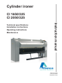
Cylinder ironer
CI 1650/325
CI 2050/325
Instruction manual
Technical specifications
Installation instructions
Operating instructions
Maintenance
Part No. D1273
Code: B12340801
September 2010
Contents
1
2
3
4
5
6
7
Safety Information ........................................................................................... 4
Explanation of Safety Messages .................................................................... 4
Safety notice ................................................................................................... 6
Important Safety Instructions .......................................................................... 7
Product description ......................................................................................... 9
Intended use ................................................................................................... 9
Description of structural components ........................................................... 10
Workplaces and noise level .......................................................................... 11
Technical data CI1650/325, CI2050/325 ...................................................... 12
Warranty and service instructions ................................................................ 14
Initial setup of the machine .......................................................................... 15
Transport and machine fastening ................................................................. 15
Setting up the machine ................................................................................. 16
Basic checks ................................................................................................. 22
Operation ........................................................................................................ 24
Operating devices and their position ............................................................ 24
Starting the machine ..................................................................................... 25
Functions ...................................................................................................... 26
Failure and information signals ..................................................................... 28
Machine function, adjustment and troubleshooting .................................. 32
Description of machine functions .................................................................. 32
Adjustments of the machine ......................................................................... 37
Troubleshooting ............................................................................................ 42
Description of the control system ............................................................... 44
General description of the control system .................................................... 44
Control panel and function keys ................................................................... 46
Menu structure and how to enter .................................................................. 47
"Manu" adjusting menu ................................................................................. 49
"Coin" adjusting menu .................................................................................. 50
Technical menu ............................................................................................. 52
Display menu ................................................................................................ 55
Central panel ................................................................................................ 55
Sigma explorer ............................................................................................. 55
Maintenance ................................................................................................... 56
Safety advice ................................................................................................ 56
Maintenance scheme ................................................................................... 56
Contents
1
Safety Information
Explanation of Safety Messages
Throughout this manual and on machine decals, you will find precautionary statements (“DANGER”, “WARNING” and
“CAUTION”) followed by specific instructions. These precautions are intended for the personal safety of the operator,
user, servicer, and those maintaining the machine.
DANGER
Indicates an imminently hazardous situation that, if not
avoided, will cause severe personal injury or death.
WARNING
Indicates a hazardous situation that, if not avoided, could
cause severe personal injury or death.
CAUTION
Indicates a hazardous situation that, if not avoided, may
cause minor or moderate personal injury or property
damage.
Additional precautionary statements (“IMPORTANT” and “NOTE”) are followed by specific instructions.
IMPORTANT: The word “IMPORTANT” is used to inform the reader of specific procedures where minor
machine damage will occur if the procedure is not followed.
NOTE: The word “NOTE” is used to communicate installation, operation, maintenance or servicing
information that is important but not hazard related.
4
1
Safety signs and labels are also placed on the unit. Those signs and labels are limited messages.
Where needed, further explanations are provided below. These signs are to be inspected for readability and
replaced when missing, damaged, or unreadable. Refer to the Maintenance section of this manual for the
periodic maintenance schedule. Refer to the parts manual for ordering information.
WARNING
Electric hazard inside.
Can cause death or serious injury.
Turn off and lock out/tag out all electric power
before opening.
WARNING
Moving parts hazard.
Can cause serious injury.
Do not operate unless all guards and covers are
in place.
Do not put hands/fingers beyond guard/cover.
WARNING
Burn hazards.
Contact with machine components or hot goods
can burn you.
Do not operate unless all guards are in place.
Use care when handling recently processed or
dried goods.
5
1
WARNING
Failure to install, maintain, and/or operate this machine according to the manufacturer's
instructions may result in conditions which can produce serious injury, death, and/or
property damage.
Do not repair or replace any part of the machine or attempt any servicing unless specifically
recommended or published in this Installation/Operation Manual and that you are qualified
to carry out.
Whenever ground wires are removed during servicing, these ground wires must be
reconnected to ensure that the machine is properly grounded and to reduce the risk of fire,
electric shock, serious injury, or death.
WARNING
Toxic and fire hazards.
Machine produces gases, fumes and lint which may be toxic or catch
fire and could result in serious injury or death.
Vent exhaust outdoors and regularly clean lint away from machine.
WARNING
Burn and crash hazards.
Push red finger guard bar daily to test. If ironer does not stop,
do not use.
Turn off and lock out/tag out all power until repaired.
Safety notice
CAUTION: Note for installation
The appliance, when installed, must be electrically grounded in accordance with local codes or, in the absence of local
codes, with the NATIONAL ELECTRICAL CODE, ANSI/NFPA 70, or Canadian Electrical Code, CSA C22.1.
The installation must comply with local codes or, in the absence of local codes, with the current National Fuel Gas Code,
ANSI Z22.1, or the current CAN/CSA B149, Installation Codes.
The appliance and its appliance main gas valve must be disconnected from the gas supply piping system during any
pressure testing of that system at test pressures in excess of 1/2 psi (3.5 kPa).
The appliance must be isolated from the gas supply piping system by closing the equipment shutoff valve during any
pressure testing of the gas supply piping system at test pressures equal to or less than 1/2 psi (3.5 kPa).
There must be provisions for adequate combustion and ventilation air, clearance around air openings and accessibility
clearances for servicing and operation.
6
1
Important Safety Instructions
Save These Instructions
WARNING
To reduce the risk of fire, electric shock, serious injury or
death to persons when using your cylinder ironer, read
and follow these basic precautions:
1. Read all instructions before using the ironer.
2. Refer to the Grounding Instructions for the proper grounding of the ironer.
3. Do not iron articles that have been previously cleaned in, washed in, soaked in, or spotted with
gasoline, dry-cleaning solvents, or other flammable or explosive substances as they give off vapors
that could ignite or explode.
4. Do not allow children to play on or around the ironer. Close supervision of children is necessary when
the ironer is used near children. This is a safety rule for all appliances.
5. Check the operation of the safety finger guard at the beginning of every shift. Operating the safety
guard should stop the ironer immediately. If this safety feature is not working properly, employees must
shut off the ironer and notify the supervisor. Do not operate the ironer until the safety finger guard is
repaired and working properly. Be sure that all other safety features, including guards and panels, are
in place before operating the ironer.
6. Never service the ironer while it is running. Never reach over, under, or behind the safety finger guard
or into any area near hot surfaces or moving parts without first shutting off the ironer at the switch and
power source. Follow this rule whenever working on the ironer to avoid serious injury from the ironer's
heat and/or pressure.
7. Never try to remove, adjust, or straighten jammed or misfed linen while the ironer is running.
Attempting to clear the jammed linen item can result in the user being caught in the linen and pulled
into the ironer. If something is jammed in the ironer, turn off the power before attempting to correct the
problem. Avoid contact with heated parts.
8. Protect yourself and fellow workers by making sure that everyone follows all the rules. Read and follow
all safety labels and warnings. Learn all aspects of the equipment such as what is hot, which parts
move, all safety shutoffs, and all emergency procedures. Do not come close to moving or heated
parts. Do not wear loose clothing, sweaters, jewelry or neck ties when near the ironer.
9. Frequent scheduled safety meetings are a must to review and update rules. If anyone is observed
breaking the rules, the supervisor or manager should be notified immediately. Reporting people for
rule breaking could save their lives or limbs.
10. Emergency shutoffs such as finger bars and emergency stop switches, should be painted red and
clearly labeled.
11. Maintenance personnel should work in a buddy system for mutual protection when working on a
ironer.
12. If in doubt, don't. Do not do anything until the supervisor or service-maintenance department has been
contacted. Only qualified personnel should service the ironer.
13. Do not install or store the ironer where it will be exposed to water and/or weather.
14. Do not tamper with the controls.
15. Do not repair or replace any part of the ironer, or attempt any servicing unless specifically
recommended in this installation/operation manual.
16. To reduce the risk of fire, DO NOT IRON plastics or articles containing foam rubber or similarly
textured rubber-like materials.
17. Keep area around the exhaust opening and adjacent surrounding area free from the accumulation of
lint, dust, and dirt.
18. The interior of the ironer and the exhaust duct should be cleaned periodically by qualified service
personnel.
7
1
19. If not installed, operated, and maintained in accordance with the manufacturer's instructions or if
there is damage to or mishandling of this product's components, use of this product could expose
you to substances in the fuel or from fuel combustion which can cause death or serious illness and
which are known to the State of California to cause cancer, birth defects, or other reproductive harm.
20. Do not put articles soiled with vegetable or cooking oil in the ironer, as these oils may not be
removed during washing. Due to the remaining oil, the fabric may catch on fire by itself.
21. To reduce the risk of fire, DO NOT put articles which have traces of any flammable substances such
as machine oil, flammable chemicals, thinner, etc., or anything containing wax or chemicals such as
in mops and cleaning cloths, or anything dry-cleaned at home with dry-cleaning solvent in the ironer.
22. ALWAYS disconnect the electrical power to the ironer before servicing. Disconnect power by shutting
off appropriate breaker of use.
23. Install this ironer according to the Installation Instructions in this manual.
All connections for electrical power, grounding, and gas supply must comply with local codes and be
made by licensed personnel when required.
WARNING
To prevent serious injury or death, read ironer
manuals before installing, operating, maintaining,
or cleaning the ironer.
8
2
Product description
Intended use
The machine, described in this manual is solely intended to use it for ironing of
sheets, small pieces of linen, pillowcases, table linen and other flat linen.
It is not suitable for garments or other thick linen.
WARNING
Any other use of the machine may involve risks to persons
and must therefore only take place after previously
obtained written approval from the manufacturer.
Equipment and components on the machine, which are important to safety and
health, have been constructed in preparation for an expected life of 15,000 operating
hours - however max. 10 years from the time of manufacture.
WARNING
The correct function of such equipment and components
within this period implies that the prescribed maintenance
is carried out.
Normally the ironed pieces are coming into the outlet tray after ironing, where the
operator can take them without any danger.
WARNING
It may involve risk of burning to the operator when taking
the sheets directly from the roll, deeper into the machine
at the outlet tray. Jams should always be taken away by
authorized personnel.
The normal, permanent working places of the operating personnel (operator) have
been marked on the layout.
WARNING
It may involve risk to the operator to work on or under
the machine. Work Stay in these areas is only allowed for
authorized personnel, and only when the machine has been
stopped, cooled down and the main switch has been locked
in position "0".
Important
This manual is a part of the delivered machine volume, and is to be handed
over to the new owner if the machine is sold.
If any doubt should occur about the contents in the manuals in your local
language, which you should have received at the time the machine was first
installed, it will always be the English text, which is valid.
9
2
Description of structural components
This machine is delivered in various types adjusted to the needs of the individual
laundry. The principal components of the machine are the following:
2
7
1
3
5
4
4
6
6
7
7
1
1. Operation panel
2. Emergency stop
3. Input conveyor
4. Outlet tray
5. Tray for wet linen
6. Foot stop (option)
7. Exhaust pipe (top or back / option)
Further information about the construction of this machine will appear from the
"Techical data" paragraph in the manual.
10
2
Workplaces and noise level
The construction and appearance of the machine are illustrated on the layout below.
On the layout, the operators’ workplaces during normal operation are indicated by the
human figures, which are sketched in.
WARNING
It may involve risk to the operator to work on or under
the machine. Work Stay in these areas is only allowed for
authorized personnel, and only when the machine has been
stopped, cooled down and the main switch has been locked
in position "0".
Normally the ironed pieces are coming into the outlet tray after ironing, where the
operator can take them without any danger.
WARNING
It may involve risk of burning to the operator when taking
the sheets directly from the roll, deeper into the machine
at the outlet tray. Jams should always be taken away by
authorized personnel.
The sound pressure levels of the machine have been measured at a height of 1.6 m
at the indicated workplaces of the operator. The value for the workplace is 60dB.
side view
top view
11
2
Technical data CI1650/325, CI2050/325
1650/325
2050/325
Diameter
323 mm
323 mm
Length
1740 mm
2140 mm
Working width
1600 mm
2000 mm
Height
1140 mm
1140 mm
Roller
Dimensions
Width
2328 mm
2728 mm
886 (650) mm
886 (650) mm
Gas-heated
625 kg
710 kg
Electrical heated
665 kg
760 kg
Electric 400V 3p + 0 50Hz
35A
35A
Electric 230V 3p + 0 50Hz
50A
65A
Gas 230V 1p + 0 50Hz
10A
10A
Gas 120V 1p + 60Hz
10A
10A
Depth (excl. feeding bag)
Net weight
Electrical connection
Other connections
Gas
1/2"
Motor drive main roll
0.18 kW
Motor ventilator
0.13 kW
Adjustable speed
1.4 -> 6 m/min.
Airflow ventilator
570m³/h
Exhaust
Ø 100 mm
Use of power
Electrical heated
18 kW
22.5 kW
Gas-heated
28 kW
35 kW
Electric consumption of gasheated ironer
0.6 kW
0.6 kW
Electric consumption of electrical
ironer
18.6 kW
23.1 kW
33 Kg/h
42 Kg/h
42.5 Kg/h
53.5 Kg/h
Capacity linen (percentage of moisture 50%)
Electrical
Gas
Ambient conditions
Permitted max. ambient temperature
Permitted max. relative moisture
of the atmosphere
+40°C
85%
12
2
Sound level measurement
Measuring points
The measuring points are defined as workplaces on the machine in question during normal operation.
Measuring method
The measuring result is an average of a measurement for 60 seconds, measured on the actual machine or on a
corresponding machine. The measuring result will appear as a LpA value. The result will have an uncertainty of ± 2 dB.
The LpA value is the reference workplace emission.
Measuring conditions
During the measurements, the machine will be equipped with legs or transport wheels and be located on a concrete floor.
Measuring equipment
The measurements are carried out with a noise meter approved for DIN IEC 651 Class 3.
Conversion table
Length: 1 m = 1,000 mm = 3.2808 ft = 39.3701 in
Weight: 1 kg = 1,000 g = 2.2046 lb
Area: 1 m² = 10.7639 ft² = 1.550 . 10³ in²
Volume: 1 m³ = 1,000 l = 35.3145 ft³ = 60.976 . 10³ in³
Temperature: °C = 0.556 . (°F - 32)
(0 °C = 32.0 °F)
Force: 1 N = 0.2248 lbf
-3
Pressure: 1 Pa = 0.145 . 10 psi
1 bar = 14.50 psi
Tension, mechanical: 1 N/mm² = 106 Pa = 145.0 lbf/in²
-6
Energy, mechanical: 1 J = 947.8 . 10 Btu
Energy, electrical: 1 kWh = 3.412 . 10³ Btu
Effect: 1 kW = 3413 Btu/h = 1.341 hp
Momentum: 1 Nm = 737.1 . 10-3 lb-ft
13
2
Warranty and service instructions
The manufacturer undertakes to replace defective parts resulting from faulty design, materials or
workmanship for a period not exceeding 12 months from contractual delivery time, or max. 2,500
operating hours. The warranty is only valid if the product is correctly installed and maintained in
accordance with the manufacturer's instruction and common practice. No warranty claim can be made
as a result of inappropriate operation, improper use, and use of force.
The manufacturer's warranty does not include damage that is due to insufficient maintenance, changes
or repair made without the written consent of the manufacturer, normal wear or defects due to war,
strike, lockout, and other force majeure or political conditions, which the manufacturer cannot control.
The same applies to damage to products, which are not supplied by the manufacturer or a construction
ordered by the buyer.
Wearing parts such as transport belts, drive belts or similar are not included in the warranty.
The manufacturer is not liable for production losses due to machine malfunctions.
Faulty parts will be replaced by the manufacturer upon receipt of the faulty components.
Transport costs to the manufacturer and back to the buyer, transport insurance and installation costs
are for the buyer's account.
14
3
Initial setup of the machine
Transport and machine
fastening
The machine has been secured with bolts on a solid wooden frame and has been
safely packed in plastic sheeting from the factory.
WARNING / DANGER
During all transport and handling of the machine, there is a risk of the
machine tipping over or falling over onto persons. In order to avoid
accidents, the following should therefore be observed:
During transport and handling with a fork-lift truck, the forks should be
situated proportional to the center of gravity as shown below and on the
packing of the machine.
Never use lifting and hoisting material with a too small lifting capacity.
See paragraph 'Technical data' concerning the weight of the machine.
The max. weight of the machine including packing is stated on the packing
of the machine.
Never move the machine on inclined or uneven surfaces.
Important
We recommend to let the wooden frame remain bolted for the use of
transport with fork-lift truck, until the machine is near the place of setting up.
15
3
Setting up the machine
Preparation of the machine
- Inspect the machine by delivery on any damage.
- The machine can be moved by a manual pallet lifter.
- Remove the packing carefully and remove the parts on top of the machine.
- Place the machine on its final position. Keep in mind that the sides of the
machine have to be free of any surroundings of at least 1 meter.
- The back must be at least 30 cm from the wall because of the turning cover.
Mechanical installation
- The machine has to be level. To check this, use a spirit level.
- The machine can be levelled by adjusting the four bolts under the machine.
Loosen the lock nuts, adjust the four bolts so the machine is level and fasten
the lock nuts.
//////////////////////////
30 cm
16
3
Exhaust system
Whenever possible, install the ironer along an outside wall where duct length can be kept to a minimum, and
make-up air can be easily accessed. The construction must not block the airflow at the rear of the ironer.
Doing so would prevent adequate air supply to the ironer combustion.
For maximum efficiency, ironer air must be exhausted to the outdoors by the shortest possible route.
Note
Never connect an ironer duct at a 90° angle to the collector dust (see picture below).
Doing so will cause excessive back pressure, resulting in poor performance.
Never connect two ironer exhaust ducts directly across from each other at the point of
entry to the collector dust.
Number of ironers
D1
D2
D3
Diameter of the exhaust pipe (in mm)
100
150
225
Ventilation aperture required section (in dm²)
0,8
1,8
4
D1
1
D2
D2
2
17
3
In order to ensure a satisfactory function of the machine exhaust system, the subsequent pipe system that is
installed in the laundry, should as minimum be dimensioned according to the following guidelines. If the pressure
loss in the piping system is increased as a result of dimensioning faults, this will cause a reduction of the exhaust
and thus the machine capacity.
In case of short distances between the ironer and the outlet to the outside, i.e. less than 15m including allowance
for bends, the exhaust pipe can be made as a channel with diameter 125mm for all machine types.
In case of longer distances, we recommend to use a larger pipe diameter. When judging the exhaust channel,
see the following tables that deal with pressure loss and the dynamic pressure by different pipe dimensions and
also deal with the equivalent pipe lengths for different part elements in an exhaust channel.
Dynamic pressure (Pd) in [Pa] and specific pressure loss (∆p) in [Pa/m] dependent on volume flow in m³/h and
pipe diameter (dia) in mm. S is the speed in m/s.
Diameter
Volume
m³/hour
250
350
450
550
650
750
850
950
1050
1150
1250
1350
100
Pd
Pa
47
93
153
229
320
426
547
683
834
1001
1182
1379
Diameter
Volume
m³/hour
250
350
450
550
650
750
850
950
1050
1150
1250
1350
125
∆p
S
Pa
14
26
42
62
85
112
143
178
217
259
305
355
m/s
8,8
12,4
15,9
19,5
23,0
26,5
30,1
33,6
37,1
40,7
44,2
47,7
Pd
Pa
19
38
63
94
131
174
224
280
342
410
484
565
160
Pd
Pa
7
14
23
35
49
65
83
104
127
153
180
210
150
∆p
S
Pa
4
8
13
19
26
34
44
54
66
79
92
107
m/s
5,7
7,9
10,2
12,4
14,7
17,0
19,2
21,5
23,8
26,0
28,3
30,6
Pd
Pa
9
18
30
45
63
84
108
135
165
198
234
272
180
∆p
S
Pa
1
2
4
5
7
10
12
15
18
22
25
29
m/s
3,5
4,8
6,2
7,6
9,0
10,4
11,7
13,1
14,5
15,9
17,3
18,7
Pd
Pa
5
9
15
22
30
41
52
65
79
95
113
131
∆p
S
Pa
2
3
5
7
10
13
17
21
25
30
35
41
m/s
3,9
5,5
7,1
8,6
10,2
11,8
13,4
14,9
16,5
18,1
19,6
21,2
200
∆p
S
Pa
1
1
2
3
4
5
7
8
10
12
14
16
m/s
2,7
3,8
4,9
6,0
7,1
8,2
9,3
10,4
11,5
12,6
13,6
14,7
Pd
Pa
3
6
10
14
20
27
34
43
52
63
74
86
∆p
S
Pa
0
1
1
2
2
3
4
5
6
7
8
9
m/s
2,2
3,1
4,0
4,9
5,7
6,6
7,5
8,4
9,3
10,2
11,1
11,9
18
3
Equivalent pipe length in m for selected single resistances :
Right-angled corner : 13.4
90 degrees smooth bend R/D = 2 : 2.1
90 degrees angular bend R/D = 2 (three sections) : 2.6
90 degrees angular bend R/D = 2 (five sections) : 2.1
In general, we recommend that the pressure loss in the exhaust pipe is kept as low as possible.
If more machines are to be connected to the same exhaust channel, it is necessary to contact a ventilating firm that can
advise you with regard to the correct dimensioning of the exhaust channel.
The pressure loss in the exhaust channel can be calculated in the following way :
Pchannel = Pd + Iength channel x ∆p
If Pchannel > 300 Pa, we recommend to increase the pipe dimension.
For this purpose, a prefabricated transfer piece is to be used.
To avoid noise, we advise to keep the maximum velocity in the pipe under 12 m/sec.
19
3
Electrical installation
The customer must install a circuit breaker for each machine.
Compare the type of network and its voltage with the data mentioned on the machine and pay attention
to the instructions. For the connection, regulations according to VDE 0100 as well as the local valid
regulations of the energy providing premises are to be taken into consideration.
It is very important to have the electric connections done by a qualified technician, in order to make sure
that the installation is effected in accordance with the prevailing standards and instructions and the valid
instructions where the machine is to be installed.
Make sure that the voltage, which is to be connected, corresponds to the voltage mentioned on the
indication plate of the ironer inside the righthanded frame. The selected network connection cannot
be less powerful than the H07RNF according to the VDE 0282 and should have a minimum diameter,
which corresponds to the nominal electric power mentioned on the ironer.
Each machine must have a main switch. With this main switch, it is possible to cut the electrical
equipment from the mains, also by persons who have not been trained in the field of electrotechnics.
This is necessary for cleaning, maintenance and reparation activities, both for the machine itself and for
the corresponding electrical equipment. In the guidance from the feeding to the electrical equipment, the
main switch is always behind the proper mains connection.
The main switch can also be applied in the supply guidance separately. It needs to be placed very close
to the machine so that there cannot be misunderstandings that the switch belongs to the machine.
When there are two or more main switches, there may not exist a dangerous situation when not all
the main switches are disconnected at the same time. For each main switch, there must be a warning,
which says that there is more than one feeding. If the main switches are placed far from each other
(not usual and not recommended), a supply will have to be made which separates the main switches by
disconnecting one of them. The control of this supply is in fact a safety-related control which applies
EN 954-1. In practice, the supply will often be executed in category 1 (EN 954-1) with bipolar contacts.
Overview circuit breakers and wire section feeding cable per machine
Circuit breaker size
Cable section
Fuse
CI325 gas
25A
1,5mm²
16A
CI325 elec 3x230V
80A
16mm²
63A
CI325 elec 3x400V
63A
6mm²
40A
20
3
Gas tube installation
- It is important to have the connections performed by an authorized mechanic in order
to be sure that the installation corresponds to the current rules and guidelines of the
country where the ironer will be installed.
- The gas supply pipe must be fitted with a stop valve, which is easily to reach.
- The ironer must be connected to the type of gas, which is stated on the apparatus.
The inlet gas pressure must correspond to the specification on the type plate, as well.
- Using a gas pipe that is too small can lead to insufficient gas supply, which results in a
poor heating and a poor ironing result.
WARNING
Test all clutches and connections for possible
leaks by means of a soap solution. NEVER by
means of a flame.
Gas supply DN16
(1/2" BSP)
- The customer must install a filter and a manual stop valve on the supply side of the machine.
- Gas installation and connection must be done by qualified personnel only.
21
3
Basic checks
Important
The first start-up of the machine should only be performed by an authorized
service engineer or a distributor.
In special cases, it may be allowed that the first start-up is performed by the
customer, but only after thorough instruction.
WARNING
If the first start-up is performed on one's own
initiative, this may cause damage to persons,
things, or environment.
- Check if all safety guards with interlocking device are closed, and that all emergency stop devices
have been deactivated.
- Start the machine.
All machines have been tested and adjusted from the factory. However, factors such as temperatures,
moisture of the atmosphere etc. may imply that an adjustment is necessary at the set-up place.
Ventilation of the room
The machine is fitted with a ventilator. This ventilator ensures vaporized moisture, and with a gasheated ironer the flue gases, being exhausted.
It is important that the room, in which the ironer has been installed, is sufficiently ventilated. You have
to take the universal rules for laundry environments into account together with the fact that the ironer
exhausts 350 m³/h. It is also important that sufficient fresh air can enter the room.
Check this before you start the machine!
22
3
Air filters
Before operating the machine, the air filter(s) must be checked.
By removing the right door, you can check if the filter on the venturi of the gas valve is not blocked by
something.
Important
Do not cover this filter at any time!
Exhaust gases
The exhaust gases of a gas-heated ironer must be inspected by an authorized mechanic.
The gas burner needs to be adjusted at prevailing rules, gas sort and gas pressure.
The measured exhaust gases may not be higher than the current rules.
Check the exhaust pipe on leaks and repair this, if so.
23
4
Operation
Operating devices and their position
The machine is equipped with the following operating devices:
1: Emergency stop button
2: Gas failure reset button
3: Start/stop button
4: “+” Button
5: “-“ Button
6: Return button
7: Left display (temperature)
8: Right display (speed)
When the power is switched to the machine by the main switch, then “
appear for 5 seconds.
” and the program version will
Then the left display will give the actual temperature (in °C or °F) and the right display will give the actual
speed (in M/min or ft/min).
24
4
Starting the machine
After switching the power to the machine, the display will show:
After 2 seconds:
X.XX
X.XX = number software version
After 5 seconds:
The ironer starts running and the heating is activated.
The small dot in the left display shows that the heating power is activated.
If the small dot is blinking, only 1 set of elements is activated (only electrical heated ironers).
25
4
Functions
Set the iron temperature
The left display shows the previous setting of the temperature in a blinking mode when the - button is
pressed.
Now the setting is changeable by pushing the - or + button. Once the setting is done, press the return
button to confirm.
Set the ironing speed
The right display shows the previous setting of the speed in a blinking mode when the + button is
pressed.
Now the setting is changeable by pushing the + or - button. Once the setting is done, press the return
button to confirm.
Pedal
The pedal can be used to spread out the linen.
The feeding and ironing belts stop turning while this pedal is being stepped on and the display will show
during 30 seconds:
WARNING
Do not use this pedal more and longer than necessary to
avoid damage of the linen by overheating. The machine
gives an acoustical signal after some seconds to warn.
Finger protection panel
For safety reasons, the feeding and ironing belts stop turning if the finger protection panel is pushed
backwards. The buzzer is activated and on the display will appear:
Important
This panel may also be pushed back due to accumulation or multiple folding
of linen, as a result of which the machine also stops and the same warning is
coming on the display. Take the linen away and reset the emergency circuit
and start the machine again.
26
4
Return button
(not with guiding ribbons)
In case a piece is fixated inside the ironer, it is possible to let the feeding belts and the main roll with
the belts turn backwards by pressing the return button continuously. It is necessary to pull the
linen tightly backwards when doing so. After having released this button, press the start button again,
otherwise the ironing process will be ended.
WARNING
Do not use this button when the linen has already
completely disappeared from the feeding belts into the
ironer. This could cause a jam inside the ironer and damage
the linen and/or the ironer.
Ironing
Now it is possible to start ironing as the temperature is high enough.
Put the linen as flat as possible on the feeding belts in order to avoid creasing.
The linen will be carried on into the ironer by the feeding belts.
Always spread open the linen by hand as flat as possible and make sure that it does not get stuck
anywhere.
Ending
The ironing process is stopped by pressing the start button.
The heating is switched off. However, in order not to get overheated, the feeding* and ironing belts,
as well as the fan keep running until the cooldown temperature has been reached.
(*) With a coin ironer, the feeding belts are not running.
The speed and “
” are alternately displayed on the right display during this cooldown period.
After the cooldown temperature is reached, the drive and the ventilator are switched off.
27
4
Failure and information signals
WARNING
If the procedure described here does not rectify
the operational failure, the technical personnel of
the laundry should be called in.
Activate hand protection
The foot pedal is pressed
There is a failure in the gas control (with a gas-heated ironer)
There is a failure in the relays for the heating elements
Important
When this signal is coming, press the reset button in case of a gas-heated
ironer (see drawing p. 15). If this problem continues, an engineer must be
consulted.
28
4
There is an overheat problem (more than 190° detected).
There is a short circuit in the temperature sensor 1.
There is a broken wire in the temperature sensor 1.
There is an overheat problem (more than 190° detected).
There is a short circuit in the temperature sensor 2.
There is a broken wire in the temperature sensor 2.
Cool down situation
The foot pedal is pressed and there is an overheat situation.
Important
The foot pedal has to be released as soon as possible. It is possible that
linen in the ironer or the belts of the ironer will be damaged by burning if the
machine is not quick started up again.
After 30 seconds, the roll will start again automatically.
29
4
The pressure switch is not activated (ventilator is not running or too much counterpressure in
exhaust pipe).
The pressure switch is activated when the ventilator is not active (pressure switch is damaged
or bypassed).
Important
An engineer must check the working of the switch and replace it in case of
malfunction.
The speed sensor is not giving signals and the motor is activated (speed sensor is damaged
or motor is not running).
Important
The foot pedal has to be released as soon as possible to prevent that linen in
the ironer will be damaged by burning.
30
4
The heating elements are switched off but the relay stays on (contacts of the relay are burnt together).
WARNING
The relays have to be replaced to prevent
overheating of the ironer and damage to linen
and ironer.
31
5
Machine function, adjustment and troubleshooting
Description of machine functions
General description of machine function
The ironer is intended to iron and dry sheets and towels. This happens by means of a heated roller,
across which the sheet is transported. The roller heats the sheet, which evaporates the residual moisture
in the sheet. After that, the sheet leaves the machine where a plate collects the sheet.
The sheet can now be taken away.
Feeding sheets and towels
The sheets have to be laid on the feeding belts in a level way. The sheet is taken into the machine
because of the running belts.
If the sheet does not cover the entire width of the feeding belts, you have to feed the sheet at the right
or left side alternately. This improves the effective function of the machine and prevents the ironing roller
from locally becoming too hot.
If a sheet that is too thick or creased, is fed, the plate above the feeding belts will be pressed in. This will
stop the machine in order to prevent the machine from being jammed. The sheet has to be laid properly
before you can start the machine with the start button. If this is not possible, you let the machine run
backwards so that the sheet comes out of the machine. This can be done by means of the control or with
the optional handle.
WARNING
A sheet being too long in the machine can burn.
Firmly deal with this matter and remove the sheet
in time.
32
5
Operating the foot pedal (option)
The machine is equipped with a foot pedal (see picture below). This foot pedal is located in the middle of
the machine between the two side frames underneath the outlet plate.
The foot pedal is used for feeding sheets in an easy way.
By pressing down the foot pedal when the machine is running, the machine will stop during 30 seconds.
In this way, you can easily and properly lay down the sheet on the feeding belts.
After releasing the foot pedal, the machine will start to run again.
33
5
Setting the temperature
The ironing temperature of the machine can be set on the control panel. Standard, this can vary between
130 and 175°C and is adjustable per degree. The range of the temperature setting can be changed in the
technical menu of the machine. This is shown on the left window of the control panel (see 7 on the picture
below).
Advice
At the first start up of the ironer, set the ironing
temperature to max. 160°C. When start ironing,
increase the temperature to the desired level.
The temperature can be changed as follows:
Press the “–“ key (5) to enter the temperature
window (7). With the “+” (4) and “–“ (5) key, you can
set the temperature. Press the ↓ key (6) to leave
the menu.
WARNING
Always watch the temperature setting when
different sorts of textile are being processed.
The temperature may not be too high, otherwise
the textile could catch fire.
Important
If you have set a new temperature that is lower than the actual ironing
roller temperature of the machine, you have to take into account that it may
take some time before the ironing roller has cooled down to the lower (set)
temperature.
34
5
Setting the speed
The speed of the ironing roller is shown on the right display (8) of the control panel.
The speed of the ironing roller can be set on the control panel. This can vary between 1.4 m/min and
6 m/min and is adjustable per 0.1 m/min. The range of the speed setting can be changed in the technical
menu of the machine.
The speed can be changed as follows:
Press the “+“ key (4) to enter the speed
window (8). With the “+” (4) and “–“ (5) key,
you can set the speed.
Press the ↓ key (6) to leave the menu.
The speed has to be set in combination with the temperature. The speed is set correctly if the sheet
leaves the machine dry and the heating device is able to remain the wanted temperature.
Take into account that it takes some time for the heating control to create a stable working point of the
machine.
35
5
Manual drive
The machine can be driven by means of the optional manual drive with manpower. This can be useful
after a voltage drop. If, during the voltage drop, a sheet is in the machine, it could catch fire. If you use
the manual drive in this case, it is possible to let the sheet come out of the machine.
If the manual drive has to be used, you need the handle, which can be found at the front machine beam
underneath the collecting plate (see 1 on the picture below).
This handle can be coupled to the motor of the machine by turning the lid (3) to the left so that a hole
becomes visible. Put the handle in this hole and turn the handle in such a way that it meshes in the bush,
which is behind the lid.
The handle is now in position 2. You can now drive the machine by turning the handle either forward or
backward.
The machine can be started with the emergency unlocking button and the start button (if it’s live again) by
closing the lid (3) (turn to the right).
Put the handle back in its original position (1), so you can always find it when you need it.
36
5
Adjustments of the machine
Guiding ironing belts
The ironing belts are guided by plates on a beam, which is placed between the ironing belts.
On the outlet side, a beam, which has a fixed position, guides these ironing belts
(see 1 on the picture below).
There is also a beam on the back side of the machine (see 2 on the picture below).
If the guiding of the ironing belts is not adjusted correctly, it will effect the life of the ironing belts in a
negative way. If the ironing belts have been dismounted/replaced, you have to recheck the guiding of
the ironing belts. Beam 2 can be reached if you remove the plating on the rear side of the machine.
37
5
Tightening the drive chain
A chain drives the machine. In the course of time, this chain will extend. It is important that the chain’s
tension is checked every month. You can check the chain’s tension by moving the left part of the chain,
at half-height, to the left and the right.
The total motion of freedom of the chain may horizontally not be more than 30mm. If it is more than
30mm, you have to tighten the chain. This can be done by slackening the four bolts B (see B on the
picture below) a few turns. By doing so, the motor becomes loose and it will move downwards.
If the motor is not moving downwards by itself, you can do this by hand. After that, screw the four bolts B
again. Check the chain tension once again. Repeat the procedure, if necessary.
Never tighten the chain too much.
WARNING
Only do this when the machine has been
stopped, cooled down and the main switch has
been locked in position "0".
38
5
Tightening the ironing belts
The ironing belts ensure the contact of the sheet with the ironing roller. These ironing belts will extend and
will become thinner in course of time. Therefore, it is important to tighten the ironing belts in time, in order
to remain the ironing effectivity of the machine.
The ironing belts are tensioned by means of springs. There is a spring on each side of the machine
(see S on the picture below).
A bolt with a nut is fastened to this spring. The position of the nut on the bolt determines the spring
force of the tensioner. The further you screw the nut on the bolt, the tauter the spring is pulled. It is
important that the spring remains tensioned permanently. This means that the nut may not come loose
from the clamping plate while the machine is running. Check the spring tension each month and adjust if
necessary.
39
5
1) Tightening the feeding belts
The feeding belts transport the sheet into the machine. The feeding belts are driven by the feeding roller.
If the contact of the feeding belts with this feeding roller is unsatisfactory, the belts will slip, which results
in a poor sheet transport. In this case, it is necessary to tighten the feeding belts.
WARNING
Only do this when the machine has been
stopped, cooled down and the main switch has
been locked in position "0".
In order to tighten the feeding belts, you first have to unscrew a number of bolts.
First loosen the bolt B1 one turn (1x on the left side and 1x on the right side of the machine) (see B1 on
the following page). Then loosen the bolts B2 one turn (2x on the left side and 2x on the right side of the
machine) (see B2 on the following page). Attention: the back bolts B2 are situated underneath the hand
protection plate. These bolts can be reached by means of a wrench.
Now the feeding bed is loose, you have to tighten the back part of the feeding bridge. Do this by
tightening the hexagon socket screws, using a socket head wrench with wrench width 6 (see T on the
following page), until the belts are tightened sufficiently.
These screws (see H_S on the following page) are each situated behind a cover plate and they are
accessible through a hole at the front of the stainless steel cover plate above the feeding roller, at the left
and right of the machine.
ATTENTION
The cover plates do not have to be removed in
order to be able to tighten the feeding belts.
After the belts have been tightened, you first have to tighten bolts B2, then bolts B1.
40
5
2) Adjusting the gap between input table and main roll
The gap between main roll and input table can be adjusted by pins coming out from the input table.
To adjust: follow the procedure on the previous page, except for bolt B1.
To move the pins forward: screw B3 until desired.
To move the pins backward: unscrew B3.
Tighten bolts B2.
B2
B1
H_S
B3
T
H_S
41
5
Troubleshooting
Starting problems
Fault
Cause
Remedy
No air has been exhausted.
"No air" on display
"No speed" on
display
Clean fan.
Clean outlet tube.
Fan blocked.
Eliminate the fault.
Vacuum valve does not connect.
Check if the valve’s switch connects.
Plug of vacuum valve is not inserted.
Insert the plug in the right input of the control.
Malfunction frequency converter.
See page 44.
Frequency converter out of order.
See page 44.
Plug of drive is not inserted.
Insert the plug in the right input of the control.
Speed sensor does not detect pulses.
Adjust distance chain wheel and sensor to 1mm.
Check position/switching point of the switch.
Out of order, replace sensor.
"No heat" on
display
"Foot" on display
Burner in reset.
Open gas tap and reset burner.
Ionization follow-up cable not inserted well in
contact of burner.
Insert plug well in burner and control print.
Plug of heating is plugged out of the burner.
Insert plug in right input of the control.
No gas in pipe at first set-up.
Make many start attempts, with resets in the
meantime, so that air is removed from the pipes.
Overheat switch tripped.
Check system and reset switch.
Fuse gas control broken.
Replace fuse after controlling system.
Foot pedal is operated.
Release the foot pedal.
Readjust the switch.
Tighten the springs.
Temperature sensor cable interrupted.
"Heat1" or
"Heat2" on display Temperature sensor out of order.
(number of the
Input on control out of order.
defective sensor)
Check cable and repair defects.
Replace the sensor by a new one.
Replace the control by a new one.
Frequency converter
Fault
Condition
OI.AC**
Drive output instantaneous over current.
Possible cause
Insufficient ramp times.
Phase to phase or phase to ground short circuit on the drives
output.
Drive requires autotuning to the motor.
Motor or motor connections changed, re-autotune drive to motor.
It.AC
I²t on drive output current.
Excessive mechanical load.
High impedance phase to phase or phase to ground short circuit
at drive output.
Drive requires re-autotuning to motor.
HFxx trip
Hardware faults.
Internal drive hardware fault.
42
5
Fault
OVL.d
hot
br.rS
AC.Lt
Condition
Solution
I x t overload (I = current, t = time).
Reduce motor current (Load).
Heatsink/IGBT temperature high.
Reduce ambient temperature or reduce motor current.
Braking resistor overload.
Call Customer Service.
Drive is in current limit.
Call Customer Service.
Burner
Fault
Cause
Continuous
malfunction
after reset
No supply voltage so also no burning
reset lamp.
Check fuses and wiring.
Overheat.
Check overheat thermostat (see Fig. 1).
Short-circuit electrode to earth.
Adjust electrode properly -> ignition probe: 3 mm from burner
(see Fig. 2).
No gas supply.
Check gas supply, gas tap and function of the gas valves.
No ignition spark.
Adjust electrode properly.
Machine has no contact with earth.
Check electrical connection of the machine.
Check overheat thermostat.
No ignition while there is a spark.
No gas supply.
Wrong adjustment gas valve.
No PWM signal on ventilator (turns full at spark).
Malfunction
burner after
2 start
attempts
Remedy
thermostat
3 mm
Fig. 1
Fig. 2
43
6
Description of the control system
General description of the control system
The control system consists of a microprocessor board with built-on display and push-buttons.
Electric heating control
For the electric heated version, the relays for the heating elements are controlled by a time related P.I.D.
controlled function built in the program of the processor, which has the opportunity of a quick reaction with
limited overshoot. The elements are activated by relays.
Gas heating
With the gas version, a PWM controlled ventilator is used, which is controlled by the microprocessor.
This ventilator blows the mix of gas and air into the burner, which means that the power of the burner is
controlled by the microprocessor. The advantage is that also here the burner is controlled with a P.I.D.
controlled function from 20-40 to 100% so that there is a quick reacting system with a low overshoot.
When the need of power is lower than 15%, the burner will be temporarily switched off.
Temperature control
The temperature of the roll is measured by Pt1000 elements that are mounted on a contact plate on the
roll. The Pt1000 are directly connected to the microprocessor board.
To prevent overheating when there is a malfunction of the Pt1000 or the microprocessor board,
a maximum temperature switch is placed, which switches off the power of the relay of the elements or the
power of the gas control unit.
temp2: left sensor
temp1: right sensor
44
6
Control of exhaust ventilator
The exhaust ventilator always turns on maximum when the ironer is switched on. An underpressure
switch is mounted, which controls the working of the exhaust ventilator. The function of this
underpressure switch is controlled when starting up the machine and will give a warning sign when the
function is not correct.
Speed control
The speed is controlled by means of a frequency regulator, which is controlled by a feedback system
through the microprocessor board.
The speed is checked by an approximated switch, which is activated by the teeth of a detection wheel.
teeth of a detection wheel
approximated switch
Start/stop function
The ironer can be started and stopped by pressing the 0/I button.
The foot pedal can temporarily stop the ironer.
45
6
Control panel and function keys
The machine is equipped with the following operating devices:
1: Emergency stop button
2: Reset gas
3: Start/stop button
4: “+” Button
5: “-“ Button
6: Return button
7: Left display (temperature)
8: Right display (speed)
When the power is switched to the machine by the main switch, “
appear during 5 seconds.
” and the program version will
Then the left display will give the actual temperature (in °C or °F) and the right display will give the actual
speed (in M/min).
46
6
Menu structure and how to enter
After installation, each ironer needs to be configured.
There are 2 different systems: Manual and Coin version.
Manual version
When the main switch is switched on, "
" appears on the right display during 5 seconds.
To enter the adjusting menus, press the I/0 button and ↓ button simultaneously until "
the right display. With the + and - button, it is possible to switch between the menus
. By pressing the ↓ button, you choose a specific menu.
" appears on
,
and
5 sec
I/0 +
I
-+
-+
+-
Coin version: hidden buttons
The hidden buttons (A) normally have no function in the coin version.
However, during the configuration, they have the same function as the manual version.
A
47
6
Menu structure
When the main switch is switched on, "
" appears on the right display during 5 seconds.
To enter the adjusting menus, activate the microswitch inside the coin box casing.
When "
" appears, keep pressing the microswitch (approximately 5 sec.) until "
" appears
on the display. Then press the “I” button to reset the emergency stop, after which the blinking "
"
menu will appear on the right display.
Then press the hidden ↓ button until 3 blinking dashes appear on the left display (approximately 2 sec.).
Release the ↓ button and press the microswitch again (approximately 5 sec.) until "
the right display.
With the + and - button, it is possible to switch between the menus
By pressing the ↓ button, you choose a specific menu.
,
" lights up on
and
.
5 sec
5 sec
I
2 sec
5 sec
-+
-+
+-
48
6
"Manu" adjusting menu
This is the group of parameters for the manual ironer with start button action.
Manu
Press the return button to continue.
t °C or t °F [default: °C]
+
Change, if necessary, by means of the + button and then press the
return button.
+
XX Cool [default: 80°C]
-
This cool down temperature can be adjusted between 80 and 100°C
by pressing the + or - button.
Then press the return button.
Iron
The following settings determine the 2 temperatures in between which
it will be possible to set the temperature during operation.
+
XXX Low [default: 130°C]
+
-
This is the low limit temperature.
It can be changed by pressing the + or - button.
Then press the return button.
XXX High [default: 175°C]
This is the high limit temperature.
It can be changed by pressing the + or - button.
Then press the return button.
+
SP.L X.X [default: 1,4 m/min]
+
This is the low limit of the speed.
It can be changed by pressing the + or - button.
Then press the return button.
SP.H X.X [default: 6 m/min]
-
This is the high limit of the speed.
It can be changed by pressing the + or - button.
Then press the return button.
+
A.St X.X [default: 0.0]
-
XXX
In order to avoid that the ironer remains unused at temperature for a
long time, it is possible to enter a switch off time.
In case of “0.0”, the cycle must be stopped manually.
Then press the return button.
End
Press the return button to confirm the setting of this parameter group.
49
6
"Coin" adjusting menu
This is the group of parameters for the coin operated ironer.
Coin
Press the return button to continue.
on t °C [default : °C]
By selecting this parameter, the temperature will be calculated and
shown in °C. Press the return button to choose this option.
+
Off t °C [default : °C]
+
+
By selecting this parameter, the temperature will be calculated in °C
but not shown during operation. Press the return button to choose this
option.
On t °F [default : °F]
By selecting this parameter, the temperature will be calculated and
shown in °F. Press the return button to choose this option.
+
Off t °F [default : °F]
+
By selecting this parameter, the temperature will be calculated in °F
but not shown during operation. Press the return button to choose this
option.
XX Cool [default : 80°C]
+
This cool down temperature can be adjusted between 80 and 100°C
by pressing the + or - button.
Then press the return button.
XXX Iron [default : 160°C]
+
This is the operating temperature of the ironer. This can be adjusted
between 130 and 175°C with the + and - button. Then press the return
button.
SP X.X [default : 1.4 m/min]
+
This is the operating speed of the ironer belts. It can be changed with
the + and - button.
Then press the return button.
C1L (coin 1 low)
-
Here, you can adjust the time in minutes and seconds with the + and button for low tariff coin 1. Then press the return button.
50
6
+
C1M (coin 1 Medium)
-
Here, you can adjust the time in minutes and seconds with the + and button for middle tariff coin 1. Then press the return button.
+
C1H (coin 1 High)
-
Here, you can adjust the time in minutes and seconds with the + and button for high tariff coin 1. Then press the return button.
+
C2L (coin 2 low)
-
Here, you can adjust the time in minutes and seconds with the + and button for low tariff coin 2. Then press the return button.
+
C2M (coin 2 Medium)
-
Here, you can adjust the time in minutes and seconds with the + and button for middle tariff coin 2. Then press the return button.
+
C2H (coin 2 High)
-
Here, you can adjust the time in minutes and seconds with the + and button for high tariff coin 2. Then press the return button.
+
Add XX [default : 00]
-
This parameter determines the minimum amount to be inserted (in
minutes) before the machine will start. It can be changed with the
+ and - button. Then press the return button.
+
Y/n ti.St
+
Y/n rEmo
+
+
If the ironing temperature drops below 130°C, the feeding belts stop
running. Select "Yes" or "no" with the + button whether the remaining
time should count down or not. Then press the return button.
Select y (yes) or n (no) by means of the + button if a central operating
system is provided. Then press the return button.
Y/n rM.St. (only if rEmo = Yes)
Select y (yes) or n (no) by means of the + button if a central operating
system is provided, by which a running cycle can be stopped (via
coin 2). Then press the return button.
Y/n Pr.cY (only if rEmo = Yes)
Select y (yes) or n (no) by means of the + button if the cycle contact
musn’t be closed continuously during the cycle. As a result, the contact
can open when the temperature is too low (see ti.St).
End
Press the return button to confirm.
51
6
Technical menu
This is the group of parameters, which effect the technical operation of the ironer. They are programmed in the factory
and normally do not need to be changed.
tEch
Press the return button to continue.
+
Adr X.X [default : 1]
X.X
This is the serial address of the ironer when connected in a network.
Only change when placed in a network. Press the return button to
choose this option.
-
Dia XXX [default : 325]
Select the roller diameter by means of this parameter. Press the return
button to choose this option.
+
+
+
Len XXXX [default : 1650-2050]
XXXX
Select the ironer length by means of this parameter. Press the return
button to choose this option.
-
Elec (Electric heating)
This parameter indicates which heating system is used in the ironer.
Press the return button to choose this option.
+
+
+
52
6
+
kp XXXX [default: gas 300] [default: elec 400]
XXXX
+
Value of the proportion of the P.I.D. regulator for the burner.
Press the return button to choose this option.
kd XXXX [default: gas 1000] [default: elec 3000]
XXXX
-
Differential value of the P.I.D. regulator for the burner. Press the return
button to choose this option.
+
ki XXXX [default: gas 0.5] [default: elec 2.0]
XX.X
-
Integrator value of the P.I.D. regulator for the burner. Press the return
button to choose this option.
+
+
Start PWM [default: 40]
XX
-
At the moment of ignition of the burner: as long as there is no
feedback measured, this value will be sent (only with gas heating).
+
Minimum PWM (default: 25)
XX
-
When the measured signal is smaller, this value will be sent (only with
gas heating).
+
PWM XX
XX
-
+
Test signal to check the PWM of the burner. The chosen value (25%,
50% or 100%) will be sent during normal operation, independently of
the temperature. After a voltage interruption, PWM will automatically
be put on "none" (only with gas heating).
L.r or Lr.SS [default: L.r]
This parameter affects the function of the frequency converter and
must therefore never be changed, unless another type of converter is
built in. Press the return button to choose this option.
Remark:
Settings kp, kd, ki, SPW, MPW and PWM are not possible when heat = steam.
53
6
rEv Y/n [default: YES] (not adjustable with coin)
Depending on the used guiding ribbon of the pressure roller, the roller
can be reversed (only with manually operated machine).
tMP 1
Temperature of probe 1.
tMP 2
Temperature of probe 2.
End
Press the return button to confirm the settings of this parameter group.
54
6
Display menu
This group contains the data of total operating hours and the total number of inserted coins.
DiSP
Press the return button to continue.
XXXX
Id. XXXX
XXX
C1 XXX
XXX
C2 XXX
This is the index concerning the total operating hours of the ironer.
This may be an interesting indicator in view of maintenance.
Press the return button to continue.
This is the total number of coins inserted in coin meter 1 (max. 999).
Press the return button to continue.
This is the total number of coins inserted in coin meter 2 (max. 999).
Press the return button to continue.
XXX
End
Press the return button to continue.
Central panel
Optional, it is possible to operate the coin version through a central panel.
In this case, not a coin selector is built in, but instead of that, an extra PC board with a relay that gives impulses
instead of the coin selector contacts.
Sigma explorer
It is possible to connect the machine to a PC with Sigma Explorer software together with other IPSO machines in a
bus system. This can be used for different coin tariffs and parameter functions.
55
7
Maintenance
Safety advice
When starting the maintenance work on the ironer, the following should be observed:
1. Turn off the gas tap in case of a gas-heating ironer.
2. Ensure that the ironer has cooled down until it has reached the environmental temperature.
3. Use proper tools in order to avoid damage to the machine, which can result in personal injury.
Maintenance scheme
The cleaning and maintenance intervals mentioned below are based on a use of 8 hours a day and 5 days a
week. If the use of this machine differs, the intervals given below can be adjusted linearly.
Daily maintenance
Cleaning:
Surrounding area
Daily clean the surrounding area of the machine. Keep it free from dust as much as possible. A clean workroom
will prolong the life of the machine as less dust and dirt will be drawn in the machine.
Filter for gas-heated ironer
Gas-heated ironers are equipped with an air filter. This filter is located in the right-hand door of the machine.
Clean it manually or with a vacuum cleaner after the machine has been turned off.
WARNING
Maintenance on the machine is solely reserved
for the maintenance personnel.
56
7
Weekly maintenance
Waxing
To prevent laundry from adhering to the ironing roller and to avoid corrosion of the ironing roller, this roller has
to be "waxed“ every week. Follow the instructions below.
Important
Only use a normal sheet or table-cloth for a grease cloth.
Set the machine to 150°C and with a speed of 1.6 mtr. per minute. Take a grease cloth and check its state.
If the grease cloth has sufficient wax, you can feed the cloth. The width of the grease cloth has to be equal to
the width of the feeding conveyor, otherwise, the ironing roller will not be fully waxed.
If the machine is not going to be used for a longer period, you have to wax the ironing roller.
With this waxing, you can prevent the ironing roller from being corroded during this particular period.
Monthly maintenance
Fan
The vapour exhaust fan on the left side of the machine will become filthy during operation. Check the fan on
this. By removing the left door, you can see the suction opening of the fan. Any filth accumulation is to be found
in the impeller of the fan. Remove this by means of the vacuum cleaner.
While cleaning this part, do not forget to clean the frame space.
fan
fan impeller
57
7
Filter gas mixture
Check filter on dust. Clean if dirty.
Frame right side
This space has to be cleaned every month (also gas-heated ironers).
Vapour exhaust beam
As a result of the laundry being ironed, dust will remain in the machine. This dust accumulates at a
certain number of places. One place is the vapour exhaust beam on top of the machine.
By removing the left door of the machine, you can see the vapour exhaust beam. Shine with an electric
torch through the hole at the left on top of the left side frame. Here, you can see the internal pollution of
the vapour exhaust beam.
If this is seriously polluted, you can open the top and clean it.
Important
If the inside of the beam is clean, it will not
guarantee that the bottom and the outside of the
vapour exhaust beam are clean. Therefore, open
the top and check it each month thoroughly.
58
7
Opening the top: unscrew bolts on the left and right side before opening the top.
Subplating dust accumulation
As a result of the laundry being ironed, dust will remain in the machine. This dust accumulates at a
certain number of places. One place is the subplating on the machine.
The plating has to be removed each month to wipe away the dust. Loosen the bolts, which fasten the
three parts of the subplating.
The easiest way is to loosen the bolts on one side (front/back) a few turns and to remove the other side
completely. The plates can now be pulled out from the remaining bolts. Placing back the bottom cover is
simplified by doing this. Clean the plates and place them back in the machine. The slot holes in the subplating have to be positioned on the inlet and outlet of the machine.
59
7
Half-yearly maintenance
Runners and axial bearing
runner
The ironing roller (S) is supported by 4 runners (W). These runners are placed on the outer end of the
ironing roller. Using the machine will wear these runners on the outside.
60
7
Check each half year the surface quality of the runners (W). If you do not check this, it can influence the
ironing roller (S) in a negative way.
Remove debris.
The runners can be dismounted if the ironing roller is not resting upon the runners. A tool is available,
which can lift the ironer roller. This tool (A) can be ordered with your IPSO dealer.
The two small screening plates underneath the machine (1 on the left and 1 on the right) have to be taken
away.
Then you have to mount the "ironing lifting plates“ (A) on both sides with 2 bolts (B), which have to be
tightened manually. Also the two bolts (C) have to be mounted. These bolts (C) have to be tightened in
such a way that the lifting plate (A) supports the roller evenly.
To prevent that the ironing roller (S) is lifted too high and so would damage internal components,
you have to determine the position of the lifting plates (A) if they just touch the roller. If so, measure (L).
The plate may not be screwed up more than 5mm (for the 8 bolts, it means not more than 4 turns from
the moment, the plate just touches the ironing roller).
The ironing roller is now lifted by the plates. The runners can be removed.
The runners are fitted with M12 bolts (D).
By removing these bolts, the runners become free and can be taken out.
Mount the runners in reverse order.
Feeding belts
The tension of the feeding belts has to be increased if the belts are not driven properly.
Exchanging the belts:
- Slacken the belts (see page 40).
- Turn the belt by hand in such a way that the connector is in front of you.
- Then pull the pin out of the belt and hold both ends of the belt.
- Now connect the new belt to the old belt by putting back the pin in the connector.
- By pulling the free end of the old belt, the new belt will be pulled through the machine.
- If the pin is in front of you again, you disconnect the old belt from the new belt and connect both ends of
the new belt.
- Do this for all belts and then tension the feeding belts (see page 40).
61
7
Ironer belts
For tensioning the ironer belts, see page 39.
Using the machine will pollute the ironing belts so that they will become smaller, longer and thinner.
If the ironing effect has become unacceptable, you have to exchange the ironing belts by new ones.
Slacken the belt tensioners by reducing the spring tension of the tensioners to zero and remove the tension nut
of the springs so that the tensioner can move freely.
Do this on the left and right side of the machine (see page 39).
Push (inside the side frame, on both sides) by means of a beam (or some other tool) the tensioner to its highest
possible position. Place the small beams vertically underneath the spanner.
Now remove the top plating, the rear plating as well as the vapour exhaust beam (see page 39) of the machine.
The pressure roll of the ironer (roll straight above the ironing roller) has to be lifted up. This can be done by
putting wooden beams from the feeding side between the main roll and the shaft of the pressure roll on both
sides (left and right). The beams can be used as a lever for lifting the roller.
Mounting new ironing belts happens in reverse order. For this purpose, please note the following points:
- The flap on the ironing belts has to be on one side of the ironing roller. Also the ironing belt has to be placed
in such a way that the flap is dragged by the ironing belt.
- Connect the ends of the ironing belt in such a way that the ends are in line. This means that the pulled part of
the belts may not protrude on a side. This could cause a mechanical load to the machine, which does not
help its life of the machine.
Drive
The chain tension has to be checked biannually as described on page 38.
The condition of the chain wheels has to be checked biannually, as well. If the chain wheels are worn down,
they have to be exchanged.
Slacken the chain by placing the motor in its top position. Loosen the hexagon socket screw of the chain wheel
that has to be exchanged one turn and remove the chain.
Important
The tightening moment of the taper lock bolts for the clamping
bush has to be 31Nm to prevent slipping.
62
7
Scrapers
Check if the scrapers are damaged. If one of the fingers of the scrapers has become bent, you have to exchange
the scraper.
Slacken the scraper beam by loosening the fixing bolt (1x left and 1x right). Now the beam can be turned so that
the fastening screws of the scraper plates become visible. A scraper plate is fastened with 5 screws.
The scrapers are fitted with plastic blocks. These blocks run over the ironing roller and will wear.
Check these blocks on wear. If this wear is to such an extend that the metal of the scraper almost pierces the
plastic, this plastic block has to be exchanged.
scraper
63