1
PR 81
HT 81
PT 81
User Instructions
Please read the manual before using the equipment!
Table of Contents
.
.
.
.
.
.
.
.
.
.
.
.
.
.
.
.
.
.
.
.
.
.
.
.
.
.
.
.
.
.
.
.
.
.
.
.
.
.
.
.
.
.
.
.
.
.
.
.
.
.
.
.
.
.
.
.
.
.
.
.
.
.
.
.
.
.
.
.
.
.
.
.
.
.
.
.
.
.
.
.
.
.
.
.
.
.
.
.
.
.
.
.
.
.
.
.
.
.
.
.
.
.
.
.
.
.
.
.
.
.
.
.
.
.
.
.
.
.
.
.
.
.
.
.
.
.
.
.
.
.
.
.
.
.
.
.
.
.
.
.
.
.
.
.
.
.
.
.
.
.
.
.
.
.
.
.
.
.
.
.
.
.
.
.
.
.
.
.
.
.
.
.
.
.
.
.
Page
. . 18
. . 18
. . 18
. . 18
. . 18
. . 18
. . 18
. . 19
. . 19
. . 20
. . 20
PART II: PR 81 RECEIVER. . . . . . . . . . . . . . . . . . . .
1 Description . . . . . . . . . . . . . . . . . . . . . . . . . . . . . .
1.1
General . . . . . . . . . . . . . . . . . . . . . . . . . . .
1.2
Controls . . . . . . . . . . . . . . . . . . . . . . . . . .
1.3
Audio Output . . . . . . . . . . . . . . . . . . . . . .
2 Setting Up . . . . . . . . . . . . . . . . . . . . . . . . . . . . . . .
2.1
Selecting the Receiving Frequency . . . . . .
2.2
Powering . . . . . . . . . . . . . . . . . . . . . . . . .
2.3
Mounting the Receiver on a Camera . . . . .
2.4
Using the Belt Clip . . . . . . . . . . . . . . . . . .
2.5
Audio Connection . . . . . . . . . . . . . . . . . .
2.6
Connecting Headphones. . . . . . . . . . . . . .
2.7
Connecting to a Camera and Headphones
2.8
Aligning the Antennas . . . . . . . . . . . . . . . .
2.9
Color Code . . . . . . . . . . . . . . . . . . . . . . . .
.
.
.
.
.
.
.
.
.
.
.
.
.
.
.
.
.
.
.
.
.
.
.
.
.
.
.
.
.
.
.
.
.
.
.
.
.
.
.
.
.
.
.
.
.
.
.
.
.
.
.
.
.
.
.
.
.
.
.
.
.
.
.
.
.
.
.
.
.
.
.
.
.
.
.
.
.
.
.
.
.
.
.
.
.
.
.
.
.
.
.
.
.
.
.
.
.
.
.
.
.
.
.
.
.
.
.
.
.
.
.
.
.
.
.
.
.
.
.
.
.
.
.
.
.
.
.
.
.
.
.
.
.
.
.
.
.
.
.
.
.
.
.
.
.
.
.
.
.
.
.
.
.
.
.
.
.
.
.
.
.
.
.
.
.
.
.
.
.
.
.
.
.
.
.
.
.
.
.
.
.
.
.
.
.
.
.
.
.
.
.
.
.
.
.
.
.
.
.
.
.
.
.
.
.
.
.
.
.
.
.
.
.
.
.
.
.
.
.
.
.
.
.
.
.
.
.
.
.
.
.
.
.
.
.
.
.
.
.
.
.
.
.
.
.
.
.
.
.
.
.
.
.
.
.
20
20
20
20
21
21
21
22
23
23
23
24
24
24
24
PART III: HT 81 HANDHELD TRANSMITTER . .
1 Description . . . . . . . . . . . . . . . . . . . . . . . . . . .
1.1
Controls . . . . . . . . . . . . . . . . . . . . . . .
1.2
Interchangeable Microphone Elements
2 Setting Up . . . . . . . . . . . . . . . . . . . . . . . . . . . .
2.1
Selecting the Carrier Frequency . . . . .
2.2
Microphone Element . . . . . . . . . . . . . .
2.3
Inserting and Testing Batteries . . . . . .
2.4
Color Code . . . . . . . . . . . . . . . . . . . . .
.
.
.
.
.
.
.
.
.
.
.
.
.
.
.
.
.
.
.
.
.
.
.
.
.
.
.
.
.
.
.
.
.
.
.
.
.
.
.
.
.
.
.
.
.
.
.
.
.
.
.
.
.
.
.
.
.
.
.
.
.
.
.
.
.
.
.
.
.
.
.
.
.
.
.
.
.
.
.
.
.
.
.
.
.
.
.
.
.
.
.
.
.
.
.
.
.
.
.
.
.
.
.
.
.
.
.
.
.
.
.
.
.
.
.
.
.
.
.
.
.
.
.
.
.
.
.
.
.
.
.
.
.
.
.
.
.
.
.
.
.
.
.
.
.
.
.
.
.
.
.
.
.
.
.
.
.
.
.
.
.
.
.
.
.
.
.
.
.
.
.
.
.
.
.
.
.
.
.
.
25
25
25
25
26
26
26
26
26
PART IV: PT 81 BODYPACK TRANSMITTER .
1 Description . . . . . . . . . . . . . . . . . . . . . . . . . .
1.1
Controls . . . . . . . . . . . . . . . . . . . . . .
1.2
Microphones. . . . . . . . . . . . . . . . . . .
2 Setting Up . . . . . . . . . . . . . . . . . . . . . . . . . . .
2.1
Selecting the Carrier Frequency . . . .
2.2
Inserting and Testing Batteries . . . . .
2.3
Connecting and Using Microphones .
2.4
Color Code . . . . . . . . . . . . . . . . . . . .
.
.
.
.
.
.
.
.
.
.
.
.
.
.
.
.
.
.
.
.
.
.
.
.
.
.
.
.
.
.
.
.
.
.
.
.
.
.
.
.
.
.
.
.
.
.
.
.
.
.
.
.
.
.
.
.
.
.
.
.
.
.
.
.
.
.
.
.
.
.
.
.
.
.
.
.
.
.
.
.
.
.
.
.
.
.
.
.
.
.
.
.
.
.
.
.
.
.
.
.
.
.
.
.
.
.
.
.
.
.
.
.
.
.
.
.
.
.
.
.
.
.
.
.
.
.
.
.
.
.
.
.
.
.
.
.
.
.
.
.
.
.
.
.
.
.
.
.
.
.
.
.
.
.
.
.
.
.
.
.
.
.
.
.
.
.
.
.
.
.
.
.
.
.
.
.
.
.
.
.
.
.
.
.
.
.
.
.
.
27
27
27
27
27
27
28
28
28
PART V: OPERATING NOTES. . . . . . . . .
1 Adjusting Transmitter and Receiver
1.1
Adjustments . . . . . . . . . . . . . .
1.2
Multichannel Systems . . . . . . .
2 Cleaning . . . . . . . . . . . . . . . . . . . . . . .
.
.
.
.
.
.
.
.
.
.
.
.
.
.
.
.
.
.
.
.
.
.
.
.
.
.
.
.
.
.
.
.
.
.
.
.
.
.
.
.
.
.
.
.
.
.
.
.
.
.
.
.
.
.
.
.
.
.
.
.
.
.
.
.
.
.
.
.
.
.
.
.
.
.
.
.
.
.
.
.
.
.
.
.
.
.
.
.
.
.
.
.
.
.
.
.
.
.
.
.
.
.
.
.
.
.
.
.
.
.
.
.
.
.
.
.
.
.
.
.
.
.
.
.
.
.
.
.
.
.
28
28
28
29
29
PART VI: APPENDIX .
1 Troubleshooting . .
2 Specifications . . . .
3 Frequency List . . .
.
.
.
.
.
.
.
.
.
.
.
.
.
.
.
.
.
.
.
.
.
.
.
.
.
.
.
.
.
.
.
.
.
.
.
.
.
.
.
.
.
.
.
.
.
.
.
.
.
.
.
.
.
.
.
.
.
.
.
.
.
.
.
.
.
.
.
.
.
.
.
.
.
.
.
.
.
.
.
.
.
.
.
.
.
.
.
.
.
.
.
.
.
.
.
.
.
.
.
.
.
.
.
.
30
30
31
92
PART I: GENERAL . . . . . . . . . . . . . . . . . . . . . .
0 FCC Statement . . . . . . . . . . . . . . . . . . . . . . .
1 Safety and Environment . . . . . . . . . . . . . . .
1.1
Safety . . . . . . . . . . . . . . . . . . . . . . . .
1.2
Environment . . . . . . . . . . . . . . . . . . .
2 Description . . . . . . . . . . . . . . . . . . . . . . . . . .
2.1
Introduction . . . . . . . . . . . . . . . . . . .
2.2
Unpacking . . . . . . . . . . . . . . . . . . . .
2.3
Optional Accessories . . . . . . . . . . . .
2.4
Frequencies . . . . . . . . . . . . . . . . . . .
2.5
Ordering Transmitters and Receivers.
.
.
.
.
.
.
.
.
.
.
.
.
.
.
.
.
.
.
.
.
.
.
.
.
.
.
.
.
.
.
.
.
.
.
.
.
.
.
.
.
.
.
.
.
.
.
.
.
.
.
.
.
.
.
.
.
.
.
.
.
.
.
.
.
.
.
.
.
.
.
.
.
.
.
.
.
.
.
.
.
.
.
.
.
.
.
.
.
.
.
.
.
.
17
I
PART I: GENERAL
FCC Statement
This equipment has been tested and found to comply with the limits for a Class B digital device, pursuant to
Parts 74, 15, and 90 of the FCC Rules. These limits are designed to provide reasonable protection against harmful interference in a residential installation. This equipment generates, uses, and can radiate radio frequency energy and, if not installed and used in accordance with the instructions, may cause harmful interference to radio
communications. However, there is no guarantee that interference will not occur in a particular installation. If this
equipment does cause harmful interference to radio or television reception, which can be determined by turning
the equipment off and on, the user is encouraged to try to correct the interference by one or more of the following measures:
• Reorient or relocate the receiving antenna.
• Increase the separation between the equipment and the receiver.
• Connect the equipment into an outlet on a circuit different from that to which the receiver is connected.
• Consult the dealer or an experienced radio/TV technician for help.
Shielded cables and I/O cords must be used for this equipment to comply with the relevant FCC regulations.
Changes or modifications not expressly approved in writing by AKG Acoustics may void the user’s authority to
operate this equipment.
This device complies with Part 15 of the FCC Rules. Operation is subject to the following two conditions: (1) this
device may not cause harmful interference, and (2) this device must accept any interference received, including
interference that may cause undesired operation.
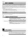
1 Safety and Environment
1.1 Safety
1. Spill no liquids on the equipment and do not drop any objects
through the ventilation slots in the equipment.
2. Do not place the equipment near heat sources such as radiators,
heating ducts, or amplifiers, etc. and do not expose it to direct sunlight, excessive dust, moisture, rain, mechanical vibrations, or
shock.
1.2 Environment
1. Be sure to dispose of used batteries as required by local waste disposal rules. Never throw batteries into a fire (risk of explosion) or
garbage bin.
2. When scrapping the equipment, remove the batteries, separate the
case, circuit boards, and cables, and dispose of all components in
accordance with local waste disposal rules.
2 Description
2.1 Introduction
18
Dear Customer:
Thank you for purchasing an AKG product. This Manual contains important instructions for setting up and operating your equipment. Please take a few minutes to
read the instructions below carefully before operating the equipment. Please
keep the Manual for future reference. Have fun and impress your audience!
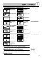
PART I: GENERAL
The PR 81 portable receiver is available separately or as a complete system with
an HT 81 handheld transmitter or PT 81 bodypack transmitter.
1 PR 81 receiver
1 screwdriver
1 mini XLR to XLR
connecting cable
2 AA size 1.5 V batteries
1 belt clip
I
2.2 Unpacking
2.2.1 PR 81 Receiver
Velcro tape for
camera mounting
1 PR 81 receiver
with
accessories
1 SA 43 stand
adapter
1 HT 81 handheld
transmitter
1 screwdriver
2 AA size 1.5 V batteries for the
handheld transmitter
1 carrying case
1 PR 81 receiver
with
accessories
1 screwdriver
1 PT 81 bodypack
transmitter
1 carrying case
2.2.2 Handheld System
2.2.3 Bodypack System
2 AA size 1.5 V batteries for the
bodypack transmitter
Please check that the package contains all the components listed above for your
system. If anything is missing contact your AKG dealer immediately.
PA 81 supply adapter for supply voltages between 5 V DC and 18 V DC
MK HP connecting cable for headphones
MK HP/C connecting cable for cameras and headphones
2.3 Optional
Accessories
2.3.1 PR 81
W 880 foam windscreen for D 880 WL1
W 3001 foam windscreen for D 3700 WL1 and C 5900 WL1
W 23 foam windscreen for C 535 WL1
CC 60 Color Coding Kit
2.3.2 HT 81
19
I
PART I: GENERAL
2.3.3 PT 81
2.4 Frequencies
CB 40 bag
Color Coding Kit
The PR 81 portable receiver, HT 81 handheld transmitter, and PT 81 bodypack
transmitter have been factory programmed for up to 15 selectable carrier frequencies. A carrier frequency label on the receiver, on the handheld transmitter,
or on the bodypack transmitter indicates the Frequency Set the unit uses and all
available carrier frequencies.
For currently available Frequency Sets and frequencies suited for intermodulation-free simultaneous operation, refer to the Frequency Lists in Part VI.
2.5 Ordering
Transmitters and
Receivers
II
If you wish to order additional transmitters or receivers operating on the same set
of frequencies as your original equipment, be sure to state the designation of your
original Frequency Set and the serial number of the original device. We need this
information to make sure your new equipment will be compatible with the original
units.
PART II: PR 81 RECEIVER
1 Description
1.1 General
The PR 81 is a portable diversity receiver you can wear on the belt or in a shirt or
jacket pocket. You may also use the supplied Velcro fastener to mount the
receiver on a camcorder. The PR 81 operates in a UHF band from 710 MHz to
860.9 MHz using a switching subband that is up to 3 MHz wide. Subject to local
frequency allocations, you can switch the PR 81 to one of up to 15 different carrier
frequencies.
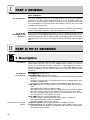
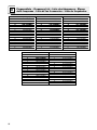
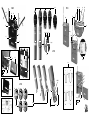
1.2 Controls
1.2.1 Top Panel
1a POWER I/O: on/off switch.
1b POWER LED: indicates battery status:
LED flashes momentarily on switching power ON and extinguishes: batteries
are O.K.
LED does not illuminate on switching power ON: no or dead batteries are in
the battery compartment.
LED constantly lights brightly: batteries will be dead in about 60 minutes.
1c RF LED: Indicates the field strength of the received signal and the squelch
status:
LED lighting green: optimum signal strength.
LED lighting red: the received signal is muted because the squelch is engaged or the receiver has been set to a different channel than the transmitter.
LED does not light: power to the receiver is OFF, no batteries are in the battery compartment, or the batteries are dead.
1d AF LED: Indicates the received audio level:
LED lighting green and flashing red on peaks: optimum audio level.
LED lighting red: audio section is overloaded.
LED does not light: audio level is too low.
1e Rotary control: Sets the volume level of the headphone output.
1f Security cover: This rotatable cover prevents the POWER switch (1a) from
being actuated unintentionally. The indicator LEDs will remain visible even if
the security cover is closed.
Refer to section 1.3 Audio
Output.
20
PART II: PR 81 RECEIVER
II
1g Antennas: Being a diversity receiver, the PR 81 uses two antennas in order
to receive the transmitter signal at two different points in space. The diversity
circuit will automatically activate the antenna that provides the better signal.
1h Color code platelet: If you use the receiver within a multichannel system,
you can remove the black plastic platelet and replace it with a different color
platelet from the optional Color Coding Kit. This allows you to identify the
various channels clearly and easily.
1i Battery compartment: Accepts the supplied 1.5 V dry batteries, rechargeable batteries of the same size (not supplied), or the optional PA 81 supply
adapter.
1j SQUELCH: The squelch will mute the receiver if the received signal is too
weak so the related noise or the self-noise of the receiver will not become
audible when the transmitter is switched OFF. Set the SQUELCH control to
minimum before switching power to the receiver ON for the first time. (For
details, refer to Part V, section 1.)
1k CHANNEL: This rotary switch selects the desired receiving frequency.
1l Battery compartment cover.
1m Screwdriver: A detachable screwdriver is provided on the inside of the battery compartment cover (1l) for adjusting the SQUELCH and CHANNEL
controls.
1.2.2 Front Panel
1n Carrier frequency table: Sticker indicating the available carrier frequencies
and the frequency set for which your receiver has been programmed.
1o Approval marks.
1p Belt clip for fixing the receiver on your belt.
1.2.3 Rear Panel
The AUDIO OUT 3-pin mini XLR connector (1r) on the receiver top panel provides
a fixed-level line output and an adjustable mono headphone output. The rotary
control (1e) lets you adjust the volume level of the headphones output.
The AUDIO OUT connector (1c) is wired as follows:
Pin 1: ground
Pin 2: line output (fixed level)
Pin 3: headphone output (adjustable)
1.3 Audio Output
In order to avoid overloading the headphone amplifier, do not connect headphones with an impedance of less than 16 Ω to the headphone output.
Important:
2 Setting Up
Prior to inserting batteries into the receiver, set the transmitter and the receiver to
the same carrier frequency. The carrier frequency tables on the transmitter (2h, 3k)
and receiver (1I) indicate the channel numbers corresponding to the various carrier frequencies.
2.1 Selecting the
Receiving Frequency
1. If the belt clip (1p) is attached to the receiver, remove the belt clip (1p) first so
you can open the battery compartment (1I):
Use a screwdriver as a lever to lift both ends of the belt clip (1p) out of the
fixing holes in the receiver side panels.
2. To open the battery compartment (1I), press down on the arrow symbol on the
battery compartment cover (1l) and push the battery compartment cover (1l)
in the direction of the arrow away from the receiver.
3. Remove the screwdriver (1m) from the battery compartment cover (1l).
4. Use the screwdriver (1m) to set the CHANNEL selector (1k) to the desired
channel.
5. Set the transmitter to the same channel referring to section 2.1 in Part III:
HT 81 Handheld Transmitter or Part IV: PT 81 Bodypack Transmitter.
21
II
PART II: PR 81 RECEIVER
Important:
If you wish to set up a multichannel system, read section 1.1
Multichannel Systems in Part V first.
2.2 Powering
To power the PR 81 portable receiver you can use the supplied 1.5 V AA size dry
batteries, 1.5 V AA size rechargeable batteries (not supplied), or the optional
PA 81 supply adapter for direct powering from a camcorder.
2.2.1 Inserting Dry or
Rechargeable Batteries
1. If the belt clip (1p) is attached to the receiver, remove the belt clip (1p) first so
you can open the battery compartment (1I):
Use a screwdriver as a lever to lift both ends of the belt clip (1p) out of the
fixing holes in the receiver side panels.
2. To open the battery compartment (1I), press down on the arrow symbol on the
battery compartment cover (1l) and push the battery compartment cover (1l)
in the direction of the arrow away from the receiver.
3. Insert the supplied batteries into the battery compartment (1I) making sure to
align them with the polarity marks inside the battery compartment (1I).
If you insert the batteries incorrectly, the receiver will not be powered.
You may use 1.5 V AA size rechargeable batteries instead of the supplied dry
batteries.
4. Set the POWER switch (1a) to "I" to switch power to the receiver ON.
The POWER LED (1b) will flash momentarily. If the batteries are fully charged
the POWER LED (1b) will extinguish.
If the POWER LED (1b) begins to light constantly the batteries will be dead in
approximately 60 minutes. Replace the batteries with new or fully charged
ones as soon as possible.
If the POWER LED (1b) does not flash the batteries are dead. Insert new batteries.
5. Use the supplied screwdriver (1m) to set the SQUELCH control (1j) fully CCW
(minimum). For details on setting the SQUELCH control (1j) refer to section 1
in Part V.
6. Align the battery compartment cover (1l) with the guide grooves on the battery
compartment (1i) and push the battery compartment cover (1l) against the
direction of the arrow to the point that the battery compartment cover (1l)
clicks shut.
Note:
2.2.2 Replacing Batteries
If the POWER LED (1b) begins to light constantly and brightly the batteries will be
dead in approximately 60 minutes.
If the POWER LED (1b) does not flash on switching power ON or the RF LED (1c)
extinguishes, the batteries are dead.
Replace the batteries with new or fully charged ones.
1. If the belt clip (1p) is attached to the receiver, remove the belt clip (1p) first so
you can open the battery compartment (1I):
Use a screwdriver as a lever to lift both ends of the belt clip (1p) out of the
fixing holes in the receiver side panels.
2. To open the battery compartment (1I), press down on the arrow symbol on the
battery compartment cover (1l) and push the battery compartment cover (1l)
in the direction of the arrow away from the receiver.
3. Remove the batteries from the battery compartment (1i).
4. Insert the new batteries into the battery compartment (1i) making sure to align
them with the polarity marks inside the battery compartment (1I).
If you insert the batteries incorrectly, the receiver will not be powered.
5. Align the battery compartment cover (1l) with the guide grooves on the battery
compartment (1i) and push the battery compartment cover (1l) against the
direction of the arrow to the point that the battery compartment cover (1l)
clicks shut.
2.2.3 PA 81 Optional
Supply Adapter
22
The optional PA 81 supply adapter allows you to power the PR 81 receiver directly from an external power supply such as a DC supply output on a camcorder. The
PR 81 supply adapter has been designed for supply voltages from 5 V DC to
PART II: PR 81 RECEIVER
II
18 V DC and has a fixed 20-in. (50-cm) connecting cable with stripped and tinned
leads.
An automatic fuse switches the PA 81 OFF if the supply voltage is shorted.
The PA 81 requires a maximum power of 1 watt.
1. Check that the voltage source on your camcorder provides a voltage between
5 V DC and 18 V DC and sufficient current to satisfy the 1-watt power requirement of the PA 81. Also check what type of connector you will need.
2. Fix a connector of the type matching your camcorder DC output to the
connecting cable of the supply adapter.
3. Open the battery compartment (1i).
4. Insert the supply adapter into the battery compartment (1i) so that the
connectng cable will pass through the opening in the bottom panel of the
receiver.
If you insert the supply adapter in a different orientation the receiver will not
be powered and you will not be able to close the battery compartment (1i).
5. Align the battery compartment cover (1l) with the guide grooves on the battery
compartment (1i) and push the battery compartment cover (1l) against the
direction of the arrow to the point that the battery compartment cover (1l)
clicks shut.
6. Plug the connecting cable into the appropriate jack on your camcorder.
If the automatic fuse has switched the supply adapter OFF because the
supply voltage has been shorted:
1. Unplug the connecting cable from the camcorder.
2. Correct the problem.
3. Plug the connecting cable into the camcorder jack again.
Refer to your camcorder
manual.
Refer to section 2.2.2
above.
Refer to your camcorder
manual.
Important:
1. Remove the backing from the supplied Velcro strips.
2. Attach one of the Velcro strips to the rear panel of the receiver.
3. Attach the other Velcro strip to the camera. In order to ensure perfect reception, position the Velcro strip so that the antennas (1g) on the receiver will
protrude above the camera.
2.3 Mounting the
Receiver on a Camera
(1s)
You can fix the belt clip (1p) to the receiver in four different ways:
2.4 Using the Belt Clip
a)
b)
c)
d)
On
On
On
On
the
the
the
the
rear panel, pointing down. The antennas (1g) will be pointing up.
rear panel, pointing up. The antennas (1g) will be pointing down.
front panel, pointing down. The antennas (1g) will be pointing up.
front panel, pointing up. The antennas (1g) will be pointing down.
1. Insert the ends of the belt clip (1p) into the fixing holes in the side panels of
the receiver.
The belt clip (1p) will lock the battery compartment cover (1l).
2. Clamp the receiver to the belt or a shirt or jacket pocket.
3. Point each antenna (1g) away from the receiver at an angle of approximately
45 degrees.
2.4.1 Attaching the
Belt Clip
Use a screwdriver as a lever to lift both ends of the belt clip (1p) out of the fixing
holes in the receiver side panels.
2.4.2 Removing the
Belt Clip
The supplied connecting cable lets you connect the line output on pin 2 of the
mini XLR jack (1r) on the receiver to an XLR input on a camcorder or mixing
console.
2.5 Audio Connection
1. If the selected input provides phantom power, switch the phantom power OFF.
Refer to the manual of your camcorder or mixing console.
2. Plug the mini XLR connector on the connecting cable into the AUDIO OUT
jack (1r) on the receiver.
3. Plug the XLR connector on the connecting cable into the desired XLR input
jack.
23
II
PART II: PR 81 RECEIVER
2.6 Connecting
Headphones
To connect a pair of headphones to the receiver, you will need an optional MK HP
adapter cable from AKG. This cable provides a mini XLR connector and a TS mini
jack for connecting headphones with a mini jack plug.
Important:
In order to avoid overloading the headphone amplifier, do not connect
headphones with an impedance of less than 16 Ω to the headphone output.
1. Plug the mini XLR connector on the adapter cable into the AUDIO OUT
jack (1r) on the receiver.
2. Connect the headphones to the mini jack on the adapter cable.
3. Use the rotary control (1e) to set the volume level for the headphones.
2.7 Connecting to a
Camera and
Headphones
The optional MK HP/C Y cable from AKG lets you connect the receiver to a camcorder or mixing console and monitor the received signal using headphones with
a mini jack plug.
Important:
In order to avoid overloading the headphone amplifier, do not connect
headphones with an impedance of less than 16 Ω to the headphone output.
1. Plug the mini XLR connector on the Y cable into the AUDIO OUT jack (1r) on
the receiver.
2. Plug the XLR connector on the Y cable into the desired XLR input jack on the
camcorder or mixing console.
3. Connect the headphones to the mini jack on the Y cable.
4. Use the rotary control (1e) to set the volume level for the headphones.
The line output level is not adjustable.
2.8 Aligning the
Antennas
For optimum reception, point each antenna (1g) away from the receiver at an
angle of 45 degrees. With the antennas aligned like this, the diversity function will
operate optimally and prevent disturbances such as noise or dropouts most
efficiently.
If you wear the receiver on the belt it makes no difference whether you point the
antennas (1g) up or down as long as you align them in a "V" as described above.
If you mount the receiver on a camcorder, align the antennas in the same way and
make sure the antennas (1g) will protrude above the camera case. This will prevent dropouts due to shadow effects of the camera case.
2.9 Color Code
To replace the black color code platelet (1) on the receiver with a different-color
platelet from the optional CC 60 Color Coding Kit,
1. Lift the end of the black color code platelet (1h) on the top panel of the receiver and remove the color code platelet (1h).
2. Select a color code platelet of the desired color from the CC 60 Color Coding
Kit and snap the selected platelet onto the receiver.
24
PART III: HT 81 HANDHELD TRANSMITTER
III
1 Description
The HT 81 handheld transmitter and matching microphone elements (optional)
provide the same acoustic performance as the equivalent hardwire microphone
versions. The microphone elements available for the HT 81 have been specifically designed for vocal use.
The HT 81 operates in a subband up to 3 MHz wide within the 710 MHz to
860.9 MHz UHF carrier frequency range. The HT 81 can be switched to a maximum of 15 different carrier frequencies depending on local frequency allocations.
The transmitter uses a dipole antenna integrated in the body.
The controls can be protected against accidental misadjustment collectively (2d)
or individually with the supplied adjustable protective ring (2j).
2a PWR: Switches the transmitter power ON ("I") and OFF ("0").
2b Status LED: Indicates battery status and audio input overload.
LED glowing dimly: batteries are OK.
LED constantly lighting brightly: batteries will be dead in about 60 minutes.
LED illuminating brightly: audio input is overloaded.
2c MIC: Mutes the audio signal (position "0") while power and carrier frequency
remain ON.
2d Color Code: If you use the transmitter in a multichannel system you can
remove the black plastic ring and replace it with a colored ring from the optional Color Coding kit to identify each wireless channel by a different color.
2e GAIN: This rotary pot allows you to match the microphone level to the transmitter’s audio section.
2f Battery Compartment: Refer to Section 2 Setting Up.
2g CHANNEL: This rotary switch selects the desired carrier frequency (depending on local allocations) or switches between the carrier frequency and its
alternative frequencies.
1.1 Controls
Prior to selecting frequencies, switch the transmitter OFF.
Important:
2h Carrier Frequency Table: A label listing the available frequencies is affixed
to the battery compartment.
2i Frequency Set Designation: The label inside the battery compartment also
indicates the designation of the Frequency Set.
2j Adjustable protective ring: Protects the controls from being misadjusted
accidentally.
The interchangeable microphone elements (2k) D 880 WL1, D 3700 WL1,
D 3800 WL1, C 5900 WL1, and C 535 WL1 are acoustically and mechanically
identical to the equivalent hardwire versions. They feature the same transducer
capsules and mechanical construction.
Extremely high gain before feedback, optimum handling noise rejection, ultimate
protection from damage, and an integrated wind and pop screen are only the
most impressive features of these microphones. For more details, refer to the
respective AKG brochures.
1.2 Interchangeable
Microphone Elements
(not supplied)
25
III PART III: HT 81 HANDHELD TRANSMITTER
2 Setting Up
2.1 Selecting the
Carrier Frequency
1. Unscrew the battery compartment cover CCW and remove the color code
ring (2d or 2j) from the transmitter.
All controls are now accessible.
2. Use the supplied screwdriver (1m) to set the CHANNEL control (2g) to the
desired channel.
3. Set the CHANNEL control (1k) on the receiver to the same channel as the
transmitter.
Important:
Be sure to switch power to the transmitter OFF every time before changing the carrier frequency. The new carrier frequency will not be activated before you switch the transmitter back ON. (If you change the carrier frequency while the transmitter is ON, the transmitter will remain
tuned to the old carrier frequency.)
Important:
If you wish to set up a multichannel system, read section 1.2 Multichannel
Systems in Part V first.
2.2 Microphone
Element
Prior to switching the transmitter on, screw the microphone element CW onto the
thread on the transmitter. All electrical connections will be made automatically.
2.3 Inserting, Testing,
and Removing
Batteries
1. Make sure that the end of the ribbon fixed inside the battery compartment (2f)
will stick out of the battery compartment (2f). (The ribbon is needed for removing the batteries.)
2. Insert the supplied batteries into the battery compartment (2f) conforming to
the polarity marks.
The transmitter will not function with incorrectly inserted batteries.
3. Set the PWR switch to "I" to switch the power to the transmitter on.
The status LED (2b) will flash momentarily. If the batteries are in good condition, the status LED (2b) will continue glowing dimly.
When the status LED (2b) illuminates brightly the batteries will be dead within
about 90 minutes. Replace the batteries with new ones as soon as possible.
If the status LED (2b) fails to illuminate the batteries are dead. Insert new batteries.
4. Replace the supplied protective ring (2j) and screw the battery compartment
cover back onto the transmitter CW.
Note:
If you prefer to cover all controls permanently, reinstall the original unadjustable
black plastic ring (2d) after adjusting the system as described in Part V, section 1.
5. Removing batteries: Pull the ribbon outward to release the batteries from
the battery compartment (2f) and remove the batteries.
2.4 Color Code
If you use the transmitter in a multichannel system you can install a colored protective ring from the optional CC 60 Color Coding Kit to identify each wireless
channel by a different color. These security rings are also adjustable.
1.
2.
3.
4.
26
Unscrew the battery compartment cover CCW.
Remove the protective ring (2j) from the transmitter.
Slide a protective ring of the desired color onto the transmitter.
Screw the battery compartment cover back onto the transmitter CW.
PART IV: PT 81 BODYPACK TRANSMITTER
IV
1 Description
You can use the PT 81 bodypack transmitter with both dynamic microphones and
condenser microphones operating on a supply voltage of approx. 7 V.
The PT 81 operates in a subband up to 3 MHz wide of the 710 MHz to 869 MHz
UHF carrier frequency range. The PT 81 can be switched to a maximum of 15 different carrier frequencies depending on local frequency allocations.
3a POWER: Switches the transmitter power ON ("I") and OFF ("0").
3b MIC: Mutes the audio signal (position "0") while power and carrier frequency
remain ON.
3c Status LED: Indicates battery status and audio input overload.
LED glowing dimly: batteries are OK.
LED constantly lighting brightly: batteries will be dead in about 60 minutes.
LED illuminating brightly: audio input is overloaded.
3d Audio Input: 3-pin mini XLR connector with both mic and line level pins that
automatically match the connector pinout of the recommended microphones
(see Part IV, section 1.2).
3e Color Code: If you use the transmitter within a multichannel system, you may
remove the black plastic platelet and replace it with a colored platelet included in the optional Color Coding Kit to identify each channel by a different
color.
3f CHANNEL: This rotary switch selects the desired carrier frequency.
1.1 Controls
Prior to selecting frequencies, switch the transmitter OFF.
Important:
3g
3h
3i
3j
Belt Clip for fixing the transmitter to your belt.
Battery Compartment: Refer to Section 2 Setting Up.
Antenna: Permanently connected, flexible antenna.
GAIN: This rotary pot allows you to match the microphone or instrument level
to the transmitter’s audio section.
3k Carrier Frequency Table: A label listing the available frequencies is affixed
to the transmitter rear panel.
3l Frequency Set Designation: The label on the rear panel also indicates the
designation of the Frequency Set.
3m Security Cover: Protects the POWER and MIC switches from being actuated
unintentionally.
The following AKG microphones have been designed specifically for direct
connection to the audio input of the PT 81:
C 417 L
C 420 L
C 444 L
CK 77 L
1.2 Microphones
(optional)
2 Setting Up
1. Open the battery compartment (3h).
All controls are now accessible.
2. Use the supplied screwdriver (1m) to set the CHANNEL control (3f) to the desired channel.
3. Set the CHANNEL control (1k) on the receiver to the same channel as the
transmitter.
2.1 Selecting the
Carrier Frequency
27
IV PART IV: PT 81 BODYPACK TRANSMITTER
Important:
Be sure to switch power to the transmitter OFF every time before
changing the carrier frequency. The new carrier frequency will not be
activated before you switch the transmitter back ON. (If you change the
carrier frequency while the transmitter is ON, the transmitter will remain
tuned to the old carrier frequency.)
Important:
If you wish to set up a multichannel system, read section 1.2 Multichannel
Systems in Part V first.
2.2 Inserting and
Testing Batteries
1. Open the battery compartment (3h).
2. Insert the supplied batteries into the battery compartment (3h) conforming to
the polarity marks.
The transmitter will not function with incorrectly inserted batteries.
3. Close the battery compartment (3h). The GAIN control (3j) remains accessible
through an opening in the battery compartment cover.
4. Rotate the security cover (3m) CW to uncover the switches.
5. Set the POWER switch (3a) to "I" to switch the power to the transmitter on.
The status LED (3c) will flash momentarily. If the batteries are in good condition, the status LED (3c) will continue glowing dimly.
When the status LED (3c) illuminates brightly the batteries will be dead within
about 90 minutes. Replace the batteries with new ones as soon as possible.
If the status LED (3c) fails to illuminate the batteries are dead. Insert new
batteries.
6. Snap the security cover (3m) back over the switches CCW.
You can wear the transmitter inside a shirt or jacket pocket, fix it to your belt
with the belt clip (3g).
Important:
Make sure the antenna will hang down freely, without being covered by
the body.
2.3 Connecting and
Using Microphones
1. Connect your microphone to the audio input (3d).
2. For details on how to use your microphone for best results, refer to the microphone instruction manual.
2.4 Color Code
To replace the black color code platelet (3e) on the transmitter with a differentcolor platelet from the optional CC 60 Color Coding Kit,
1. Lift the end of the black color code platelet (3e) on the top panel of the transmitter and remove the color code platelet (3e).
2. Select a color code platelet of the desired color from the CC 60 Color Coding
Kit and snap the selected platelet onto the transmitter.
V
PART V: OPERATING NOTES
1 Adjusting the Transmitter and Receiver
1.1 Adjustments
28
1. Handheld transmitter: Using the supplied screwdriver (1m), set the GAIN
control (2e) so that on the receiver the AF LEDs (1h) will light green and the AF
LED (1d) on the receiver as well as the status LED (2b) on the transmitter will
only flash on the loudest signal peaks.
Bodypack transmitter: Using the supplied screwdriver (1m), set the GAIN
control (3j) so that on the receiver the AF LEDs (1h) will light green and the AF
LED (1d) on the receiver as well as the status LED (3c) on the transmitter will
only flash on the loudest signal peaks.
PART V: OPERATING NOTES
2. The red AF LED (1hd on the receiver constantly lighting red and/or the status
LED (2b, 3c) on the transmitter lighting constantly means the transmitter is
overloaded. Turn the GAIN control (2e) or (3j) on the transmitter CCW to the
point that the above LEDs will only flash occasionally.
3. Set the audio input level on your camcorder or on the mixer channel to which
the receiver is connected.
If the selected input provides phantom power, switch the phantom power OFF.
4. If unwanted noise becomes audible, turn the SQUELCH control (1j) CW just
enough to suppress the noise.
The RF LED (1c) will light red every time the squelch mutes the audio output
of the receiver.
Never set the squelch threshold higher than absolutely necessary. The
higher the squelch threshold, the lower the sensitivity of the receiver
and thus the usable range between transmitter and receiver.
V
Refer to the manual of
your camcorder or
mixing console.
Important:
5. Check the field strength of the received signal. If the RF LED (1c) is dark, reposition the receiver and/or transmitter such that the RF LED (1c) will light green.
6. The RF LED (1c) on the receiver illuminating means no signal is received or
the squelch is active.
Switch the transmitter ON, move closer to the receiver, or turn the SQUELCH
control (1j) CCW to the point that the RF LED (1c) will light green constantly.
1. Be sure to assign a separate carrier frequency to each transmission channel
(transmitter + receiver).
2. Set the transmitter and receiver to one of the frequencies marked with * in the
carrier frequency tables (1n, 2h, 3k).
1.2 Multichannel
Systems
If reception on the selected carrier frequency is disturbed, set the carrier frequencies for all channels up or down one or two notches using
the respective CHANNEL controls (1k, 2g, 3f) on each transmitter and
receiver.
This is necessary to provide the minimum frequency spacing required
for intermodulation-free multichannel operation.
Important:
Do not operate two or more channels on the same frequency at the
same time and location. This would cause unwanted noise due to radio
interference.
Important:
2 Cleaning
Use a soft cloth moistened with water to clean the receiver and transmitter
surfaces.
29
VI PART VI: APPENDIX
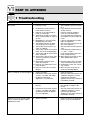
1 Troubleshooting
Problem
No sound.
Possible Cause
1. Receiver is OFF.
Remedy
1. Set POWER switch on receiver
to "I".
2. insert batteries into transmitter
and/or receiver.
3. Connect receiver output to
mixer or camcorder input.
4. Turn up audio level control on
camcorder or channel fader on
mixer.
5. Connect microphone to audio
input on bodypack.
6. Set transmitter and receiver to
the same frequency.
7. Set transmitter on/off switch to
"ON".
8. Insert batteries conforming to
"+" and "-" marks.
9. Insert new batteries into transmitter and/or receiver.
10. Move closer to receiver or turn
down SQUELCH control.
2. No batteries inside the transmitter and/or receiver.
3. Receiver is not connected to
mixer or camcorder.
4. Audio level control on camcorder or channel fader on mixer is
at zero.
5. Microphone is not connected
to bodypack transmitter.
6. Transmitter operates on different frequency than receiver.
7. Transmitter on/off switch is at
"OFF" or "MUTE".
8. Transmitter and/or receiver batteries are not inserted properly.
9. Transmitter and/or receiver batteries are dead.
10. Transmitter is too far away from
receiver or SQUELCH control
set too high.
11. Obstructions between trans11. Remove obstructions from betmitter and receiver.
ween transmitter and receiver.
12. Receiver is invisible from trans- 12. Avoid spots where you cannot
mitter location.
see receiver.
13. Receiver is too close to metal
13. Move receiver away from or
objects.
remove interfering objects.
Noise, crackling, unwanted signals. 1. Antenna location.
1. Relocate receiver.
2. Interference from other wireless 2. Set transmitter and receiver to
systems, TV, radio, CB radios,
a different frequency; switch
or defective electrical
interfering or defective
appliances or installations.
appliances of or have electrical
installation checked.
Distortion.
1. GAIN control is set too high or
too low.
Momentary loss of sound ("dropouts") at some locations within
performance area.
1. Antenna location.
30
1. Turn GAIN control down or up
just enough to stop the distortion.
2. Interference from other wireless 2. Set transmitter and receiver to
systems, TV, radio, CB radios,
a different frequency; switch
or defective electrical applianinterfering or defective
ces or installations.
appliances of or have electrical
installation checked.
1. Relocate receiver. If dead spots
persist, mark and avoid them.
PART VI - APPENDIX
VI
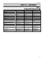
2 Specifications
Carrier frequency range
Modulation
Audio bandwidth
Frequency stability (-10°C to
+50°C)
Rated deviation
T.H.D. at 1 kHz
Compander
Signal/noise ratio
RF output
Current consumption
Power requirement
Battery life
Audio input level for rated
deviation
Input impedance
Condenser mic power supply
Audio outputs
HT 81
710 to 860.9 MHz
FM
50 to 20,000 Hz
PT 81
710 to 860.9 MHz
FM
50 to 20,000 Hz
PR 81
710 to 860.9 MHz
FM
50 to 20,000 Hz
±10 ppm
30 kHz
<0.5%
Yes
typ. 50 dB(A)
10 mW
150 mA typ.
2 x 1.5 V AA size
batteries
>12 hours
±10 ppm
30 kHz
<0.5%
Yes
typ. 50 dB(A)
10 mW
180 mA typ.
2 x 1.5 V AA size
batteries
>10 hours
±10 ppm
<0.8%
Yes
>108 dB(A)
2 x 1.5 V AA size
batteries
>6 hours
350 mV/1 kHz
220 kΩ
-
1400 mV/1 kHz
220 kΩ//320 pF
6 V/6.8 kΩ (pin 3)
-
length: 240 mm (9.4 in.)
dia.: 36 mm (1.4 in.)
245 g (8.7 oz.)
92 x 65 x 20 mm
(3.6 x 2.6 x 0.8 in.)
76 g (2.7 oz.)
Unbal. LINE (pin 2):
-6 dBm (600 Ω)
Pin 3: 30 mW typ.
(16 to 100 Ω)
92 x 65 x 20 mm
(3.6 x 2.6 x 0.8 in.)
80 g (2.8 oz.)
Headphone output:
Size (WxDxH)
Net weight
31
3
Frequenzliste - Frequency List - Liste des fréquences - Elenco
delle frequenze - Lista de las frecuencias - Lista de frequências
Set: UK69B (UKSpot)
CHANNEL
0
1
2
3
4
5
6
7
8
9
A
B
C
D
E
F
Set: US58
FREQ.
OFF
858.200MHz*
860.400MHz*
860.900MHz*
860.900MHz
860.900MHz
860.900MHz
860.900MHz
860.900MHz
860.900MHz
860.900MHz
860.900MHz
860.900MHz
860.900MHz
860.900MHz
860.900MHz
CHANNEL
0
1
2
3
4
5
6
7
8
9
A
B
C
D
E
F
Set: EU62
CHANNEL
0
1
2
3
4
5
6
7
8
9
A
B
C
D
E
F
92
FREQ.
OFF
802,525MHz
803,025MHz
803,100 MHz
803,550 MHz
803,575 MHz
803,625 MHz
803,675 MHz
804,775 MHz
804,800MHz
804,850 MHz
805,175 MHz
805,200 MHz
805,275 MHz
805,300 MHz
805,800 MHz
Set: EU59
FREQ.
OFF
734.400MHz
734.600MHz*
734.800MHz
735.000MHz
735.200MHz
735.400MHz
735.600MHz
735.800MHz
736.000MHz*
736.200MHz
736.400MHz
736.600MHz
736.800MHz
737.000MHz*
737.200MHz
CHANNEL
0
1
2
3
4
5
6
7
8
9
A
B
C
D
E
F
Set: EU63
CHANNEL
0
1
2
3
4
5
6
7
8
9
A
B
C
D
E
F
FREQ.
OFF
812,775 MHz
812,800 MHz
812,825 MHz
813,050 MHz
813,075 MHz
813,100 MHz
813,125 MHz
813,150 MHz
813,175 MHz
813,200 MHz
813,250 MHz
813,275 MHz
813,300 MHz
813,750 MHz
813,800 MHz
FREQ.
OFF
777.600MHz
777.800MHz*
778.000MHz
778.200MHz
778.400MHz*
778.600MHz
778.800MHz
779.000MHz
779.200MHz*
779.400MHz
779.600MHz
779.800MHz
780.000MHz
780.200MHz*
780.400MHz
93
PR 81
PT 81
2k
3b
3a
3c
3d
1e
45°
1b
1d
1c
1a
1r
1g
3i
3m
45°
1f
3e
1g
1h
2a
2b
3g
2c
1p
3m
1j
HT81
HT81
1l
HT81
2g
PT81
0000Z0000
SNR:01001 AKG Set:EUS..
1:000.000
9:000.000 MHz
2:000.000
10:000.000 MHz
3:000.000
11:000.000 MHz
4:000.000
12:000.000 MHz
5:000.000
13:000.000 MHz
6:000.000
1n
HT 81
2e
1j
1l
1k
3k/3l
3g
1o
2 x 1.5V
II
1i
3g
3j
2h/2i
3f
HT 81
1m
A
B
HT81
C
HT81
2f
HT81
+
2 x 1.5V
3h
HT81
2d/2j
1s
HT81
2d/2j
–
2 x 1.5V
III
IV
+
E
–
D
–
+
+
–
I
–
+
+
–
1p