1
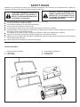
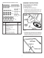
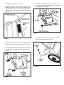
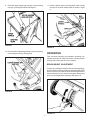
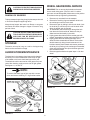
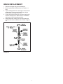
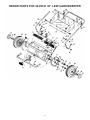
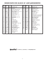
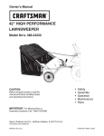
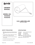
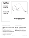
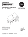
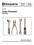
™
owners
manual
Model No.
45-02181
26" LEAF/LAWNSWEEPER
CAUTION:
Read Rules for
Safe Operation
and Instructions
Carefully
Safety
Assembly
Operating
Maintenance
Repair Parts
the fastest way to purchase parts www.speedepart.com
PRINTED IN USA
FORM NO. 40261 (4/24/07)
SAFETY RULES
Remember, any equipment can cause injury if operated improperly or if the user does not understand how to operate the
equipment. Exercise caution at all times when using this equipment.
CAUTION: VEHICLE BRAKING AND
STABILITY MAY BE AFFECTED WITH THE
ADDITION OF AN ACCESSORY OR AN
ATTACHMENT. BE AWARE OF CHANGING
CONDITIONS ON SLOPES.
LOOK FOR THIS SYMBOL TO POINT OUT
IMPORTANT SAFETY PRECAUTIONS. IT
MEANS — ATTENTION! BECOME ALERT!
YOUR SAFETY IS INVOLVED.
Do not allow anyone to operate the sweeper without proper instructions.
Do not permit children to operate sweeper.
Eye protection should be worn while operating sweeper.
Do not push or tow sweeper too close to a fire.
Do not attempt to remove wire or string wrapped around brush while brush is rotating.
Operate sweeper at reduced speed on rough terrain, in ditches and on hillsides to prevent tipping and loss of control.
Stay alert for holes or other hidden hazards.
This sweeper is not meant for street or highway use. Watch for traffic when sweeping near roadways.
Keep all nuts, bolts and screws tight to be sure equipment is in safe working condition.
Sweeper should be stopped and inspected for damage after striking a foreign object and damage should be repaired
before operating the equipment.
Follow maintenance instructions as outlined in this manual.
CARTON CONTENTS
1. Sweeper Housing Assembly
2. Hopper Bag
3. Upper Handle
4. Lower Handle Leg Stand (2)
5. Short Bag Rod
6. Long Bag Rod
ASSEMBLY INSTRUCTIONS
HARDWARE PACK (NOT SHOWN FULL SIZE)
TOOLS REQUIRED FOR ASSEMBLY
(1)Phillips Screwdriver
(1)Adjustable Wrench
(1) 7/16" Open End or Box Wrench
1. Assemble the two Handle Leg Stand Tubes to the
Sweeper Housing, using two hex bolts 1/4-20 x 1-1/4"
long, flat washers and 1/4-20 hex lock nuts, per handle.
See figure 1. Only hand tighten at this time.
Ref.
No.
Description
Hex Bolt, 1/4-20 x 1-1/4"
Flat Washers 1/4" I.D.
Hex Lock Nuts 1/4-20
Bag Rod Clips
Curved Head Bolts 1/4-20 x 1"
Palnut 1/4"
Plastic Caps (for bag rods)
Plastic Caps (for leg stands)
A
B
C
D
E
F
G
H
Qty.
4
4
8
4
4
2
2
2
FIGURE 1
2. Assemble the Upper Handle Tube over the Handle Leg
Stand Tubes. See figure 2. Align holes in handle and
assemble the Bag Rod Clips to the handle as shown
and fasten with curved head bolts and hex lock nuts.
FIGURE 2
3. Now tighten the four bolts from step 1.
7. Assemble the two plastic rod caps to the rod ends of
the bottom bag rod. Assemble two Palnuts to the ends
of the top bag rod. See figure 5.
4. Assemble a bag rod clip to the inside of each lower
handle tube using a curved head bolt secured down
against the clip using a 1/4" lock nut. The open end of
the clips should face towards the sweeper housing. See
figure 3.
FIGURE 5
8. Assemble the two plastic caps 3/4" x 7/8" onto the ends
of the leg stands as shown in figure 6.
FIGURE 3
5. Slide the long bag rod (28-1/2" long) through the stiched
bag flap on the top of the hopper bag as shown in figure
4.
6. Slide the short bag rod (25-1/2" long) through the stiched
bag flap on the bottom of the hopper bag as shown in
figure 4.
FIGURE 6
FIGURE 4
9. Place the upper hopper bag and bag rod into the bag
rod clips on the hopper handle. See figure 7.
11. Hook the elastic straps on the bag flaps under the bag
rod clips on the lower handle tubes as shown in figure
9.
FIGURE 7
FIGURE 9
10. Place the lower hopper bag and bag rod into the opening
on the sweeper housing. See figure 8.
OPERATION
Take care when operating your sweeper. Operating your
sweeper according to these instructions will help prevent
damage and prolong the life of your sweeper.
BRUSH HEIGHT ADJUSTMENT
To adjust your sweeper brushes to the best operating height,
loosen the hand knob and slide the height adjustment tube
down to raise or up to lower the brushes. Best adjustment is
when brushes are set 1/2" down into the grass. Always mow
grass to even height before sweeping. See figure 10.
FIGURE 8
FIGURE 10
WHEEL GEARS/PAWL SERVICE
CAUTION: EYE PROTECTION SHOULD BE
WORN WHILE OPERATING SWEEPER
IMPORTANT: Do not remove both wheels at the same
time to avoid mixing parts. (The R.H. and L.H. ratchet
gears are not interchangeable.) Make notes on the position
of washers and snap rings during disassembly.
DUMPING OF SWEEPER
1. Remove only one wheel from the sweeper.
2. Remove the retaining rings and washers which hold
the ratchet gear onto the brush shaft.
3. Remove the gear by sliding it off the brush shaft. (Look
for the drive pin, which may fall out of the brush shaft
when the ratchet gear is removed.
4. To reassemble, insert the drive pin through the hole
near the end of the brush shaft. Make sure the pin
slides back and forth easily in the shaft.
5. Lightly grease the shaft and fill the ratchet gear with
grease. Assemble the ratchet gear back onto the shaft.
6. Lightly grease the axle and the gear teeth on the
wheel and then reassemble the wheel. The brushes
should rotate only during forward movement. If the
brushes rotate by both forward and reverse movement,
the drive pin is jamming in the ratchet gear. Dissamble,
clean and lubricate the drive pin and ratchet gear and
then reassmble wheel.
7. Remove opposite wheel and repeat steps 1-6 for that
wheel.
To dump sweeper hopper bag, simply tip the sweeper forward
or lift off the complete hopper bag frame.
Always dump hopper after each use. Damp or wet grass
and leaves will cause damage to hopper if stored for long
periods of time.
CAUTION: DO NOT DUMP THE SWEEPER
TOO CLOSE TO A FIRE AS THE BRUSHES
AND BAG CAN BE DESTROYED BY
EXCESSIVE HEAT OR FLAME.
STORAGE
The entire unit may be hung on a wall or the hopper bag
frame can be removed for storage.
LUBRICATION/MAINTENANCE
The bearings in the sweeper have been prelubricated at
the factory. It is recommended that a few drops of light
oil be added to the brush shaft bearings twice a year.
The wheels should be removed to clean gears every two
years. After cleaning, apply an even coat of light grease.
See figures 11, 12 and 13.
NOTE:
To remove the wheel, pop off hub cap with a screw
driver and remove retaining "E" ring and flat washer.
FIGURE 12
FIGURE 11
BRUSH REPLACEMENT
1. Remove the hopper bag from lawnsweeper.
2. Brush replacement should be done one brush at a
time.
3. Tip the sweeper forward on housing for ease of brush
replacement. Do not remove hex bolt from double
brush retainers through brush shaft.
4. Loosen hex bolts and hex lock nuts from single brush
retainers. See figure 13. Slide brush out of retainers,
making not of over-lap bristles position.
5. Install new brush, making sure over-lap bristles are
postioned the same as before and as shown in figure
13.
FIGURE 13
REPAIR PARTS FOR 45-02181 26" LEAF/LAWNSWEEPER
REPAIR PARTS FOR 45-02181 26" LEAF/LAWNSWEEPER
REF.
NO.
PART
NO.
QTY.
1
44600
2
23784
3
44286
4
43681
5
44680
6
1543-69
7
44695
8 R19111116
9
43720
10
44946
11
23866
12
44598
13
43070
14
44684
15
1038
16
44685
17
40007
18 716-0106
19
44679
20
49946
21 741-0249
22
44692
23
43064
24 2674-32
25
48651
26
48652
27
47046
1
1
4
1
1
1
1
1
1
1
2
2
4
2
2
2
2
2
2
2
4
4
4
2
1
1
2
DESCRIPTION
Housing
Height Adjustment Plate
Bolt, Hex 10-32 x 5/8"
Bolt, Carriage 5/16-18 x 1-1/2"
Washer, Nylon
Washer, Nylon 21/64
Washer, Bowed
Washer, 11/32 x 11/16
Knob, 5/16"
Height Adjustment Tube
Dust Cover
Axle
Washer, 3/8"
Jam Nut, 3/8-24
Lock Nut, 3/8-24
Shoulder Spacer
Washer, .596 x 1.125 x .025
"E" Ring, 5/8"
Flange Bearing, .59
Wheel Assembly
Flange Bearing, .63
Bolt, Hex 5/16-18 x 1/2"
Lock Nut, 5/16-18
Black Hub Cap
Pinion, L.H. 11 T.
Pinion, R.H. 11 T.
Pin, Drive
REF.
NO.
28
29
30
31
32
33
34
35
36
37
38
39
40
41
42
43
44
45
46
47
49
50
51
PART
NO.
QTY.
44125
44687
1650-21
23782
43661
43013
44681
23580
23581
43012
44603
44595
44683
44682
726-0106
44688
44696
43978
1509-90
43088
44694
43662
47189
40261
4
2
4
1
4
8
4
4
8
8
1
2
1
1
2
2
4
4
4
4
1
4
12
1
DESCRIPTION
Flat Washer, .62 x 1"
Plastic Cap, .207
Retaining Ring, .594
Brush Shaft
Bolt, Hex 1/4-20 x 1"
Lock Nut, 1/4-20
Brush, 13-1/4"
Brush Retainer, Double Bracket
Brush Retainer, Single Clip
Bolt, Hex 1/4" x 3/4"
Upper Handle Tube
Handle Leg Tube
Bag Rod, 1/4" x 25-1/2"
Bag Rod, 1/4" x 28-1/2"
Palnut, 1/4"
Plastic Cap, 3/4"
Bag, Rod Clip
Bolt, Curved 1.4-20 x 1"
Bolt, Hex 1/4-20 x 1-1/4"
Washer, 1/4"
Hopper Bag
Lock Nut, 10-32
Nylock Nut, 1/4-20
Owner's Manual
the fastest way to purchase parts www.speedepart.com
NOTES
10
NOTES
11
the fastest way to purchase parts www.speedepart.com
REPAIR PARTS
Agri-Fab, Inc.
303 West Raymond
Sullivan, IL. 61951
217-728-8388
www.agri-fab.com
This document (or manual) is protected under the U.S. Copyright Laws and the copyright laws of foreign countries,
pursuant to the Universal Copyright Convention and the Berne convention. No part of this document may be reproduced
or transmitted in any form or by an means, electronic or mechanical, including photocopying or recording, or by any
information storage or retrieval system, without the express written permission of Agri-Fab, Inc. Unauthorized uses and/or
reproductions of this manual will subject such unauthorized user to civil and criminal penalties as provided by the United
States Copyright Laws.
© 1992 Agri-Fab, Inc.