1
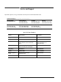
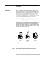
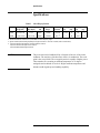
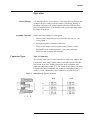
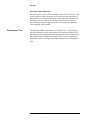
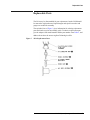
281A/B Adapters
Operating and Service
Manual
Manual part number: 00281-90045
Printed in USA
Print Date: May 2001
Supersedes: October 2000
Notice
The information contained in this document is subject to change without
notice.
Agilent Technologies makes no warranty of any kind with regard to this
material, including, but not limited to, the implied warranties of
merchantability and fitness for a particular purpose. Agilent Technologies
shall not be liable for errors contained herein or for incidental or
consequential damages in connection with the furnishing, performance, or
use of this material.
Agilent Technologies assumes no responsibility for the use or reliability of
its software on equipment that is not furnished by Agilent Technologies.
This document contains proprietary information which is protected by
copyright. All rights are reserved. No part of this document may be
photocopied, reproduced, or translated to another language without prior
written consent of Agilent Technologies.
RESTRICTED RIGHTS LEGEND
Use, duplication, or disclosure by the U.S. Government is subject to
restrictions as set forth in subparagraph (c)(1)(ii) of the Rights in Technical
Data and Computer Software clause at DFARS 252.227-7013 for DOD
agencies, and subparagraphs (c)(1) and (c)(2) of the Commercial Computer
Software Restricted Rights clause at FAR 52.227-19 for other agencies.
Agilent Technologies, Inc.
1400 Fountaingrove Parkway
Santa Rosa, CA 95403-1799, U.S.A.
© Copyright 2000–2001
Agilent Technologies, Inc.
ii 281A/B Operating And Service Manual
What You’ll Find In This Manual…
•
•
•
•
•
Overview, page 1
Specifications, page 2
Inspection and Shipping, page 3
Operation, page 5
Replaceable Parts, page 7
281A/B Operating And Service Manual iii
Warranty
Custom systems are warranted by contractual agreement between Agilent
Technologies and the customer.
Certification
Agilent Technologies, Inc., certifies that this product met its published
specifications at the time of shipment from the factory. Agilent Technologies
further certifies that its calibration measurements are traceable to the
United States National Institute of Standards and Technology (NIST,
formerly NBS), to the extent allowed by the Institute’s calibration facility,
and to the calibration facilities of other International Standards
Organization members.
Warranty
This Agilent Technologies system product is warranted against defects in
materials and workmanship for a period corresponding to the individual
warranty periods of its component products. Instruments are warranted for a
period of one year. During the warranty period, Agilent Technologies will, at
its option, either repair or replace products that prove to be defective.
Warranty service for products installed by Agilent Technologies and certain
other products designated by Agilent Technologies will be performed at
Buyer’s facility at no charge within Agilent Technologies service travel
areas. Outside Agilent Technologies service travel areas, warranty service
will be performed at Buyer’s facility only upon Agilent Technologies’ prior
agreement and Buyer shall pay Agilent Technologies’ round trip travel
expenses. In all other areas, products must be returned to a service facility
designated by Agilent Technologies.
For products returned to Agilent Technologies for warranty service, Buyer
shall prepay shipping charges to Agilent Technologies and Agilent
Technologies shall pay shipping charges to return the product to Buyer.
However, Buyer shall pay all shipping charges, duties, and taxes for products
returned to Agilent Technologies from another country.
Agilent Technologies warrants that its software and firmware designated by
Agilent Technologies for use with an instrument will execute its
programming instructions when properly installed on that instrument.
Agilent Technologies does not warrant that the operation of the instrument,
or software, or firmware will be uninterrupted or error free.
LIMITATION OF WARRANTY. The foregoing warranty shall not apply
to defects resulting from improper or inadequate maintenance by Buyer,
Buyer-supplied software or interfacing, unauthorized modification or
misuse, operation outside of the environmental specifications for the
product, or improper site preparation or maintenance.
iv 281A/B Operating And Service Manual
NO OTHER WARRANTY IS EXPRESSED OR IMPLIED. AGILENT
TECHNOLOGIES SPECIFICALLY DISCLAIMS THE IMPLIED
WARRANTIES OR MERCHANTABILITY AND FITNESS FOR A
PARTICULAR PURPOSE.
EXCLUSIVE REMEDIES. THE REMEDIES PROVIDED HEREIN ARE
BUYER’S SOLE AND EXCLUSIVE REMEDIES. AGILENT
TECHNOLOGIES SHALL NOT BE LIABLE FOR ANY DIRECT,
INDIRECT, SPECIAL, INCIDENTAL, OR CONSEQUENTIAL
DAMAGES, WHETHER BASED ON CONTRACT, TORT, OR ANY
OTHER LEGAL THEORY.
YEAR 2000. Agilent Technologies warrants that each Agilent Technologies
hardware, software, and firmware product on Agilent Technologies’
Corporate Price List (dated July 1, 1998 or later) delivered under the
product’s contract of sale will be able to accurately process date data
(including, but not limited to, calculating, comparing, and sequencing) from,
into, and between the twentieth and twenty-first centuries, and the years
1999 and 2000, including leap year calculations, when used in accordance
with the product documentation provided that all other products (that is,
hardware, software, firmware) used in combination with such Agilent
Technologies product(s) properly exchange date data with it. If the
agreement requires that specific Agilent Technologies products must
perform as a system in accordance with the foregoing warranty, then that
warranty will apply to those Agilent Technologies products as a system, and
Customer retains sole responsibility to ensure the year 2000 readiness of its
information technology and business environment. The duration of this
warranty extends through January 31, 2001.
The remedies available under this warranty will be defined in, and subject to,
the terms and limitations of the warranties contained in the contract of sale.
To the extent permitted by local law, this warranty applies only to branded
Agilent Technologies products and not to products manufacture by others
that may be sold or distributed by Agilent Technologies. Nothing in this
warranty will be construed to limit any rights or remedies provided
elsewhere in the contract of sale with respect to matters other than year 2000
compliance.
Assistance
Product maintenance agreements and other customer assistance agreements
are available for Agilent Technologies products.
For assistance, call your local Agilent Technologies Sales and Service Office
(refer to “Service and Support” on page vi).
281A/B Operating And Service Manual v
Service and Support
By internet, phone, or fax, get assistance with all your test and measurement needs.
Online assistance: www.agilent.com/find/assist
United States
(tel) 1 800 452 4844
Latin America
(tel) (305) 269 7500
(fax) (305) 269 7599
Canada
(tel) 1 877 894 4414
(fax) (905) 282-6495
New Zealand
(tel) 0 800 738 378
(fax) (+64) 4 495 8950
Japan
(tel) (+81) 426 56 7832
(fax) (+81) 426 56 7840
Australia
(tel) 1 800 629 485
(fax) (+61) 3 9210 5947
Europe
(tel) (+31) 20 547 2323
(fax) (+31) 20 547 2390
Asia Call Center Numbers
Country
Phone Number
Fax Number
Singapore
1-800-375-8100
(65) 836-0252
Malaysia
1-800-828-848
1-800-801664
Philippines
(632) 8426802
1-800-16510170 (PLDT Subscriber
Only)
(632) 8426809
1-800-16510288 (PLDT
Subscriber Only)
Thailand
(088) 226-008 (outside Bangkok)
(662) 661-3999 (within Bangkok)
(66) 1-661-3714
Hong Kong
800-930-871
(852) 2506 9233
Taiwan
0800-047-866
(886) 2 25456723
People’s Republic of
China
800-810-0189 (preferred)
10800-650-0021
10800-650-0121
India
1-600-11-2929
000-800-650-1101
vi 281A/B Operating And Service Manual
Safety and Regulatory Information
Review this product and related documentation to familiarize yourself with
safety markings and instructions before you operate the instrument. This
product has been designed and tested in accordance with international
standards.
WARNING
The WARNING notice denotes a hazard. It calls attention to a procedure,
practice, or the like, that, if not correctly performed or adhered to, could result
in personal injury. Do not proceed beyond a WARNING notice until the
indicated conditions are fully understood and met.
CAUTION
The CAUTION notice denotes a hazard. It calls attention to an operating
procedure, practice, or the like, which, if not correctly performed or adhered
to, could result in damage to the product or loss of important data. Do not
proceed beyond a CAUTION notice until the indicated conditions are fully
understood and met.
Instrument Markings
!
When you see this symbol on your instrument, you should refer to the instrument’s
instruction manual for important information.
This symbol indicates hazardous voltages.
The laser radiation symbol is marked on products that have a laser output.
This symbol indicates that the instrument requires alternating current (ac) input.
The CE mark is a registered trademark of the European Community. If it is
accompanied by a year, it indicates the year the design was proven.
The CSA mark is a registered trademark of the Canadian Standards Association.
1SM1-A
This text indicates that the instrument is an Industrial Scientific and Medical Group 1
Class A product (CISPER 11, Clause 4).
This symbol indicates that the power line switch is ON.
This symbol indicates that the power line switch is OFF or in STANDBY position.
281A/B Operating And Service Manual vii
Safety Earth
Ground
This is a Safety Class I product (provided with a protective earthing
terminal). An uninterruptible safety earth ground must be provided from the
main power source to the product input wiring terminals, power cord, or
supplied power cord set. Whenever it is likely that the protection has been
impaired, the product must be made inoperative and secured against any
unintended operation.
Before Applying Power
Verify that the product is configured to match the available main power
source as described in the input power configuration instructions in this
manual. If this product is to be powered by autotransformer, make sure the
common terminal is connected to the neutral (grounded) side of the ac power
supply.
viii 281A/B Operating And Service Manual
Overview
Description
Agilent 281 adapters provide a convenient means of coupling between
waveguide and coaxial systems. Power can be transmitted in either direction,
and each adapter covers the full frequency range of its waveguide size with
an SWR of less than 1.30. The flanges are lapped to a slight, controlled
convexity to assure minimum leakage at the waveguide joint. A probe
transforms the waveguide impedance to the 50-ohm impedance of coaxial
line. Complete specifications for the adapters are given in Table 1.
Examples of the waveguide flange and coaxial connectors used on these
adapters are shown in Figure 1. One type of flange and two types of coaxial
connectors are used: Type N female connectors (which are compatible with
connectors conforming to MILS-71), are available on all 281A adapters and
Amphenol precision 7-mm connectors (available on the 281B adapters). The
7-mm connector features precise alignment, a clearly defined reference
plane, and low RF leakage. In addition, any pair can be connected together
without an adapter. Option 13 adapters have stainless steel Type N female
connectors and are available on the P281B.
Figure 1
Adapters Showing Flange Types and Coaxial Connector Styles
281A/B Adapters Operating and Service Manual 1
Specifications
Specifications
Table 1
Model
X281A
P281B
Frequency
Range (GHz)1
8.20 to 12.40
12.40 to 18.00
281A/B Specfications
Fits Waveguide Size
Nom. OD(in.)
EIA
1 x 1/2
WR90
0.702 -0.391
WR62
Equivalent
Flange
Coaxial
Connector2
UG135/U
N female
1-7/16
37
1/4
0. 1
UG419/U
APC-73
1
26
3/16
0. 1
(in)
Length
(mm)
(lb)
Weight
(kg)
1. Maximum Reflection Coefficient: 0.11 (1.25 SWR) over entire frequency range.
2. Typical maximum power handling capability for the Type N and APC-7 connectors is 200 W (refer to caution below).
3. Option 013 furnished with stainless steel Type N female connector.
Option 012 furnished with Type N male connector.
Option 006 adds additional alignment holes.
CAUTION
The power that can be handled will be a function of the size of the center
conductor. The majority of the heat flow will be via conduction. The weak
point is the coax portion. The waveguide portion is capable of higher power.
These numbers are assuming an ambient temperature of 25 degrees
centigrade and an altitude of sea level. Higher ambient temperatures and
altitude would degrade power-handling capability.
2 281A/B Adapters Operating and Service Manual
Inspection and Shipping
Inspection and Shipping
Inspection
Mechanical Check
If external damage to the shipping carton is evident, the carrier’s agent
should be present when the adapter is unpacked. Check the adapter for
external damage. If damage is evident, refer to Claims, below, for
recommended claim procedure. If the shipping carton is not damaged, check
the packaging material for signs of stress that indicate rough handling in
transit. If the adapter appears undamaged, perform the electrical check.
Electrical Check
The electrical performance of the adapter should be checked as soon as
possible after receipt against the specifications shown in Table 1. If the
adapter does not perform within the specifications, see the following
paragraphs for recommended claim procedure and repackaging the
instrument.
Claims
If physical damage is evident, or if the adapter does not meet electrical
specifications when received, notify the carrier and the nearest Agilent
Technologies office
Shipping
Using Original Packaging
The same containers and material used in factory packaging can be obtained
through Agilent offices.
If the adapter is being returned to Agilent Technologies for servicing, attach
a tag indicating the type of service required, return address, and model
number. Also, mark the container FRAGILE to assure careful handling
Using Other Packaging
The following general instructions should be used for repackaging with
commercially available materials:
1. Wrap the adapter in heavy paper or plastic. (If shipping to a Agilent
Technologies office or service center, attach a tag indicating the type of
service required, return address, and model number.)
2. Use a strong shipping container. A double-wall carton made of
350-pound test material is adequate.
281A/B Adapters Operating and Service Manual 3
Inspection and Shipping
3. Use enough shock-absorbing material (3 to 4-inch layer) around all sides
of the adapter to provide firm cushion and prevent movement inside the
container.
4. Seal the shipping container securely
5. Mark the shipping container FRAGILE to assure careful handling.
4 281A/B Adapters Operating and Service Manual
Operation
Operation
Protest Flanges
Assemble Carefully
Care should be taken to protect the face of the flange from any damage that
would prevent close surface-to-surface contact. Any burring, denting, or
scratching will increases RF leakage and the reflection coefficient of the
joint. The supplied plastic cover should be used to protect the flange when
the adapter is not in use.
When connecting an adapter to a waveguide.
1. Make sure the rectangular ports are oriented the same way (i.e., not
"cross-guided").
2. Align ports carefully to minimize reflections.
3. Clamp or bolt flanges securely together so that pressure is evenly
distributed over the contacting surfaces. Loose joints and flange
distortion result in leakage and mismatch.
Connector Types
Type N Connectors
Two versions of the Type N coaxial connector are used on the adapters: one
is used on the 281A model, and the other is used in the Option 13B model.
The version on the 281A model is plated brass and is compatible with
connectors conforming to MIL-C-71. The version on the Option 13B model
is stainless steel and is compatible with connectors conforming to MIL-C-71
or MIL-C-39012. Dimensions of these connectors are given in Figure 2.
Figure 2
Dimensions of Type N Connectors
281A/B Adapters Operating and Service Manual 5
Operation
Precision 7 mm Connectors
Except for Option 13, the 281B model adapter has a APC-7 precision 7-mm
coaxial connector. These connectors rely on uniform end-to end contact of
both conductors for electrical continuity. Consequently, the condition of the
contacting surfaces is critical: they should be kept clean and smooth. To
prevent damage when the adapter is not in use, the connector’s threaded
sleeve should be fully extended.
Performance Test
The maximum SWR for the Adapters are listed in Table 1. When making
these measurements, the test results must be less than those listed in Table 1
plus the measurement uncertainty of the measurement system. Measurement
may be made using a standard reflectometer setup. To ensure satisfactory
performance, make sure flanges and coaxial connectors are not damaged or
worn.
6 281A/B Adapters Operating and Service Manual
Replaceable Parts
Replaceable Parts
The 281A may be disassembled for part replacement, but the 281B should
be returned to Agilent because liquid nitrogen and special wrenches and
gauges are needed for assembly.
The exploded view of Figure 3 gives information for ordering replacement
parts and can be used as an assembly guide. To obtain a replacement part
give the adapter’s full model number and the part number from Table 2, and
address the order to the nearest Agilent Technologies office.
Figure 3
281A Replacement Parts
281A/B Adapters Operating and Service Manual 7
Replaceable Parts
Table 2
281A Replaceable Parts
Item No.
Description
Model No.
Agilent Part No.
1
RF Connector Body
X281A
5020-0213
2
Probe Assembly
X281A
not applicable
Probe Body1
Probe Insulator
00281-20025
1
00281-20106
3
Probe Case
X281A
X281A-5
4
X-band
X281A
00281-20017
X-band
X281A
5040-0354
P-band
P281B
5040-0358
Flange Cap (not shown)
1. This part is a subcomponent of item number 2 (Probe Assembly for X281A).
NOTE
All 281B adapters should be returned for part replacement.
8 281A/B Adapters Operating and Service Manual