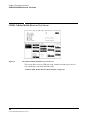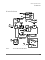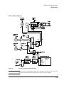
1
Agilent Technologies E8285A CDMA Mobile Station Test Set Reference Guide Firmware Version A.05.00 and Above Agilent Part Number: E8285-90016 Printed in U. S. A. June 2000 Rev. C 1 © Copyright Agilent Technologies 1999, 2000 Notice Information contained in this document is subject to change without notice. All Rights Reserved. Reproduction, adaptation, or translation without prior written permission is prohibited, except as allowed under the copyright laws. This material may be reproduced by or for the U.S. Government pursuant to the Copyright License under the clause at DFARS 52.227-7013 (APR 1988). Agilent Technologies Learning Products Department 24001 E. Mission Liberty Lake, WA 99019-9599 U.S.A. 2 S:\agilent\e8285\REFGUIDE\MANUAL\frntmt.fb Manufacturer’s Declaration This statement is provided to comply with the requirements of the German Sound Emission Directive, from 18 January 1991. This product has a sound pressure emission (at the operator position) < 70 dB(A). • • • • Sound Pressure Lp < 70 dB(A). At Operator Position. Normal Operation. According to ISO 7779:1988/EN 27779:1991 (Type Test). Herstellerbescheinigung Diese Information steht im Zusammenhang mit den Anforderungen der Maschinenlärminformationsverordnung vom 18 Januar 1991. • • • • Schalldruckpegel Lp < 70 dB(A). Am Arbeitsplatz. Normaler Betrieb. Nach ISO 7779:1988/EN 27779:1991 (Typprüfung). 3 Safety Considerations GENERAL This product and related documentation must be reviewed for familiarization with safety markings and instructions before operation. This product has been designed and tested in accordance with IEC Publication 1010, "Safety Requirements for Electronic Measuring Apparatus," and has been supplied in a safe condition. This instruction documentation contains information and warnings which must be followed by the user to ensure safe operation and to maintain the product in a safe condition. SAFETY EARTH GROUND A uninterruptible safety earth ground must be provided from the main power source to the product input wiring terminals, power cord, or supplied power cord set. CHASSIS GROUND TERMINAL To prevent a potential shock hazard, always connect the rear-panel chassis ground terminal to earth ground when operating this instrument from a dc power source. SAFETY SYMBOLS ! Indicates instrument damage can occur if indicated operating limits are exceeded. Indicates hazardous voltages. Indicates earth (ground) terminal WARNING A WARNING note denotes a hazard. It calls attention to a procedure, practice, or the like, which, if not correctly performed or adhered to, could result in personal injury. Do not proceed beyond a WARNING sign until the indicated conditions are fully understood and met. CAUTION A CAUTION note denotes a hazard. It calls attention to an operation procedure, practice, or the like, which, if not correctly performed or adhered to, could result in damage to or destruction of part or all of the product. Do not proceed beyond an CAUTION note until the indicated conditions are fully understood and met. 4 S:\agilent\e8285\REFGUIDE\MANUAL\frntmt.fb Safety Considerations for this Instrument WARNING This product is a Safety Class I instrument (provided with a protective earthing ground incorporated in the power cord). The mains plug shall only be inserted in a socket outlet provided with a protective earth contact. Any interruption of the protective conductor inside or outside of the product is likely to make the product dangerous. Intentional interruption is prohibited.. Whenever it is likely that the protection has been impaired, the instrument must be made inoperative and be secured against any unintended operation. If this instrument is to be energized via an autotransformer (for voltage reduction), make sure the common terminal is connected to the earth terminal of the power source. If this product is not used as specified, the protection provided by the equipment could be impaired. This product must be used in a normal condition (in which all means for protection are intact) only. No operator serviceable parts in this product. Refer servicing to qualified personnel. To prevent electrical shock, do not remove covers. Servicing instructions are for use by qualified personnel only. To avoid electrical shock, do not perform any servicing unless you are qualified to do so. The opening of covers or removal of parts is likely to expose dangerous voltages. Disconnect the product from all voltage sources while it is being opened. Adjustments described in the manual are performed with power supplied to the instrument while protective covers are removed. Energy available at many points may, if contacted, result in personal injury. The power cord is connected to internal capacitors that my remain live for 5 seconds after disconnecting the plug from its power supply. For Continued protection against fire hazard, replace the line fuse(s) only with 250 V fuse(s) or the same current rating and type (for example, normal blow or time delay). Do not use repaired fuses or short circuited fuseholders. 5 WARNING: Always use the three-prong ac power cord supplied with this product. Failure to ensure adequate earth grounding by not using this cord may cause product damage. This product is designed for use in Installation Category II and Pollution Degree 2 per IEC 1010 and IEC 664 respectively. FOR INDOOR USE ONLY. This product has autoranging line voltage input, be sure the supply voltage is within the specified range. To prevent electrical shock, disconnect instrument from mains (line) before cleaning. Use a dry cloth or one slightly dampened with water to clean the external case parts. Do not attempt to clean internally. Ventilation Requirements: When installing the product in a cabinet, the convection into and out of the product must not be restricted. The ambient temperature (outside the cabinet) must be less than the maximum operating temperature of the product by 4° C for every 100 watts dissipated in the cabinet. If the total power dissipated in the cabinet is greater than 800 watts, then forced convection must be used. Product Markings CE - the CE mark is a registered trademark of the European Community. A CE mark accompanied by a year indicated the year the design was proven. CSA - the CSA mark is a registered trademark of the Canadian Standards Association. 6 S:\agilent\e8285\REFGUIDE\MANUAL\frntmt.fb Agilent Technologies Warranty Statement for Commercial Products Agilent Technologies E8285A CDMA Mobile Station Test Set Duration of Warranty: 1 year 1. Agilent Technologies warrants Agilent Technologies hardware, accessories and supplies against defects in materials and workmanship for the period specified above. If Agilent Technologies receives notice of such defects during the warranty period, Agilent Technologies will, at its option, either repair or replace products which prove to be defective. Replacement products may be either new or like-new. 2 Agilent Technologies warrants that Agilent Technologies software will not fail to execute its programming instructions, for the period specified above, due to defects in material and workmanship when properly installed and used. If Agilent Technologies receives notice of such defects during the warranty period, Agilent Technologies will replace software media which does not execute its programming instructions due to such defects. 3. Agilent Technologies does not warrant that the operation of Agilent Technologies products will be uninterrupted or error free. If Agilent Technologies is unable, within a reasonable time, to repair or replace any product to a condition as warranted, customer will be entitled to a refund of the purchase price upon prompt return of the product. 4 Agilent Technologies products may contain remanufactured parts equivalent to new in performance or may have been subject to incidental use. 5. The warranty period begins on the date of delivery or on the date of installation if installed by Agilent Technologies. If customer schedules or delays Agilent Technologies installation more than 30 days after delivery, warranty begins on the 31st day from delivery. 6 Warranty does not apply to defects resulting from (a) improper or inadequate maintenance or calibration, (b) software, interfacing, parts or supplies not supplied by Agilent Technologies, (c) unauthorized modification or misuse, (d) operation outside of the published environmental specifications for the product, or (e) improper site preparation or maintenance. 7 TO THE EXTENT ALLOWED BY LOCAL LAW, THE ABOVE WARRANTIES ARE EXCLUSIVE AND NO OTHER WARRANTYOR CONDITION, WHETHER WRITTEN OR ORAL IS EXPRESSED OR IMPLIED AND AGILENT TECHNOLOGIES SPECIFICALLY DISCLAIMS ANY IMPLIED WARRANTIES OR CONDITIONS OR MERCHANTABILITY, SATISFACTORY QUALITY, AND FITNESS FOR A PARTICULAR PURPOSE. 7 8 Agilent Technologies will be liable for damage to tangible property per incident up to the greater of $300,000 or the actual amount paid for the product that is the subject of the claim, and for damages for bodily injury or death, to the extent that all such damages are determined by a court of competent jurisdiction to have been directly caused by a defective Agilent Technologies product. 9 TO THE EXTENT ALLOWED BY LOCAL LAW, THE REMEDIES IN THIS WARRANTY STATEMENT ARE CUSTOMER’S SOLE AND EXCLUSIVE REMEDIES. EXCEPT AS INDICATED ABOVE, IN NO EVENT WILL AGILENT TECHNOLOGIES OR ITS SUPPLIERS BE LIABLE FOR LOSS OF DATA OR FOR DIRECT, SPECIAL, INCIDENTAL, CONSEQUENTIAL (INCLUDING LOST PROFIT OR DATA), OR OTHER DAMAGE, WHETHER BASED IN CONTRACT, TORT, OR OTHERWISE. FOR CONSUMER TRANSACTIONS IN AUSTRALIA AND NEW ZEALAND: THE WARRANTY TERMS CONTAINED IN THIS STATEMENT, EXCEPT TO THE EXTENT LAWFULLY PERMITTED, DO NOT EXCLUDE RESTRICT OR MODIFY AND ARE IN ADDITION TO THE MANDATORY STATUTORY RIGHTS APPLICABLE TO THE SALE OF THIS PRODUCT TO YOU. ASSISTANCE Product maintenance agreements and other customer assistance agreements are available for Agilent Technologies products. For any assistance, contact your nearest Agilent Technologies Sales and Service Office. 8 S:\agilent\e8285\REFGUIDE\MANUAL\frntmt.fb DECLARATION OF CONFORMITY according to ISO/IEC Guide 22 and EN 45014 Manufacturer’s Name: Agilent Technologies Manufacturer’s Address: Spokane Division 24001 E. Mission Avenue Liberty Lake, Washington 99019-9599 USA declares that the product Product Name: Model Number: Product Options: CDMA Mobile Station Test Set Agilent Technologies E8285A All conforms to the following Product specifications: Safety: IEC 61010-1:1990+A1+A2 / EN 61010-1:1993+A2 EMC: CISPR 11:1990 / EN 55011:1991- Group 1, Class A IEC 61000-3-2:1995 / EN 61000-3-2:1995 IEC 61000-3-3:1995 / EN 61000-3-3:1994 EN 50082-1 : 1992 IEC 801-2:1991 - 4kV CD, 8kV AD IEC 801-3:1984 - 3 V/m IEC 801-4:1988 - 0.5 kV Signal Lines, 1 kV Power Lines Supplementary Information: This product herewith complies with the requirements of the Low Voltage Directive 73/23/EEC and the EMC Directive 89/336/EEC and carries the CE-marking accordingly. Spokane, Washington USA June 16, 1999 Vince Roland Reliability & Regulatory Engineering Manager European Contact: Your local Agilent Technologies Sales and Service Office or Agilent Technologies GmbH Department ZQ/Standards Europe, Herrenberger Strasse 130, D-71034 Böblinger, Germany (FAX+49-7031-14-3143) 9 Agilent Technologies E8285A Support Contacts The documentation supplied with your test set is an excellent source of reference, applications, and service information. Please use these manuals if you are experiencing technical problems: • • Applications information is included in the Agilent Technologies E8285A CDMA Mobile Station Test Set Application Guide ( E8285-90019) Calibration and repair information are in the Agilent Technologies E8285A CDMA Mobile Station Test Set Assembly Level Repair Manual (E8285-90033). If you have used the manuals and still have application questions, contact your local Agilent Technologies Sales Representative. Repair assistance is available for the Agilent Technologies E8285A CDMA Mobile Test Set from the factory by phone and e-mail. Parts information is also available from Agilent Technologies. When calling or writing for repair assistance, please have the following information ready: • • • • Instrument model number (Agilent Technologies E8285A) Instrument Serial Number (tag located on the rear panel). Installed options - if any (tag located on the rear panel). Instrument firmware revision (displayed at the top of the screen when the Test Set is powered up, and is also displayed on the CONFIGURE screen). Support Telephone Numbers: 1 800 827 3848 (U.S. only) 1 509 921 3848 (International) 1 800 227 8164 (Agilent Technologies Direct Parts Ordering, U.S. only) 1 916 783 0804 (Agilent Technologies Service Parts Identification, U.S. & Intl.) Electronic mail (Internet): [email protected] 10 S:\agilent\e8285\REFGUIDE\MANUAL\frntmt.fb Table 1 Regional Sales and Service Offices United States of America: Agilent Technologies Test and Measurement Call Center P.O. Box 4026 Englewood, CO 80155-4026 Canada: Agilent Technologies Canada Inc. 5150 Spectrum Way Mississauga, Ontario L4W 5G1 (tel) 1 800 452 4844 (tel) 1 877 894 4414 Europe: Agilent Technologies European Marketing Organization P.O. Box 999 1180 AZ Amstelveen The Netherlands (tel) (3120) 547 9999 Japan: Agilent Technologies Japan Ltd. Measurement Assistance Center 9-1 Takakura-Cho, Hachioji-Shi, Tokyo 192-8510, Japan (tel) (81) 456-56-7832 (fax) (81) 426-56-7840 Latin America: Agilent Technologies Latin America Region Headquarters 5200 Blue Lagoon Drive, Suite #950 Miami, Florida 33126 U.S. A. (tel) (305) 267 4245 (fax) (305) 267 4286 Australia/New Zealand: Agilent Technologies Australia Pty Ltd. 347 Burwood Highway Forest Hill, Victoria 3131 (tel) 1 800 629 485 (Australia) (fax) (61 3) 9272 0749 (tel) 0 800 738 378 (New Zealand) (fax) (64 4) 802 6881 Asia Pacific: Agilent Technologies 24/F, Cityplaza One, 111 Kings Road, Taikoo Shing, Hong Kong (tel) (852) 3197 7777 (fax) (852) 2506 9233 11 In this Book Throughout this manual the term "Test Set" is used to denote the Agilent Technologies E8285A. Test Set screens shown in this manual may not match those displayed on the Test Set in every detail. Chapter 1, Key and Miscellaneous Knob Descriptions This chapter describes functions of the Test Set’s keys. Chapter 2, Connector Descriptions This chapter describes the Test Set’s connectors. Chapters 3 Screen Descriptions This chapters describe the Test Set’s screens for CDMA testing and for analog testing.. Chapters 4 Field Descriptions This chapters describe the fields found on the Test Set’s screens for CDMA testing and for analog testing. 12 S:\agilent\e8285\REFGUIDE\MANUAL\frntmt.fb Documentation Map All of the following literature, with the exception of the Instrument BASIC User’s Handbook, is shipped with the Agilent Technologies E8285A on a CD-ROM. The Agilent part number of the CD-ROM is E8285-10004. Unless a delete option is specified, paper versions of the Application Guide and Condensed Programming Reference Guide are also shipped with each Test Set. If option OBW is ordered, paper versions of the Reference Guide and the User’s Guide will also be included with the Test Set. Reference Guide (E8285-90016)1 This guide describes the functions performed by each front panel key, front and rear panel connector, and display screen and field. GPIB command examples for each display field are included. User’s Guide (E8285-90018) This guide provides a tutorial-style overview of operating the Test Set, including a section designed to help you get started. Status reporting, IBASIC controller information, and error message descriptions are also included. Application Guide (E8285-90019) This guide contains step-by-step procedures and programming examples for calibrating the Test Set, setting up a call, and making measurements on CDMA and AMPS mobile stations. Tips for increasing measurement throughput are also included, as well as a procedure for logging protocol messages. Condensed Programming Reference Guide (E8285-90020) This pocket-sized guide contains a complete listing of GPIB commands, along with a cross-reference between front-panel display fields and the corresponding commands. Assembly Level Repair (E8285-90033) This guide includes procedures for performing periodic adjustments, verifying performance, troubleshooting, and repairing the Test Set. Block diagrams and a list of replaceable parts are also included. 1. Part numbers listed are Agilent Technologies part numbers unless otherwise stated. 13 Instrument Basic User’s Handbook (E2083-90000) This guide contains a complete listing of IBASIC commands. This guide is not shipped with the Test Set. For ordering information, contact your nearest regional sales office. Specifications (5968-8839E) This document provides a short description of the Agilent E8285A and lists the operating specifications. This document also includes the specifications for Agilent Technologies 83217A Option 001, 003, and 004 software. 14 S:\agilent\e8285\REFGUIDE\MANUAL\frntmt.fb Contents Description of Keys Keys.................................................................................................................................................... 31 Address .................................................................................................................................................................. Answer................................................................................................................................................................... Assign .................................................................................................................................................................... Average.................................................................................................................................................................. Call/Page................................................................................................................................................................ Cancel .................................................................................................................................................................... EEX ....................................................................................................................................................................... End/Release ........................................................................................................................................................... Enter ...................................................................................................................................................................... Hold ....................................................................................................................................................................... IBASIC reset ......................................................................................................................................................... Increment ÷10, Increment set, Increment x10....................................................................................................... K1 - K5, & K1’- K3’ ............................................................................................................................................. Local ...................................................................................................................................................................... Low limit, High limit............................................................................................................................................. Meas reset ............................................................................................................................................................. Meter ..................................................................................................................................................................... No Ratio W............................................................................................................................................................ On/Off.................................................................................................................................................................... POWER ................................................................................................................................................................. Preset ..................................................................................................................................................................... Previous ................................................................................................................................................................. Print ....................................................................................................................................................................... Recall..................................................................................................................................................................... Ref set.................................................................................................................................................................... Register.................................................................................................................................................................. Release................................................................................................................................................................... Save ....................................................................................................................................................................... Shift ....................................................................................................................................................................... Yes On/Off............................................................................................................................................................. 0 to 9, decimal point (.), +/-, and A to F................................................................................................................ 31 31 32 32 34 34 34 35 35 35 35 36 39 40 40 44 45 49 49 49 49 49 50 50 51 54 54 54 55 56 56 Symbol Keys ...................................................................................................................................... 57 Backspace .............................................................................................................................................................. Down-Arrow, Up-Arrow ....................................................................................................................................... Units-of-Measure Keys ......................................................................................................................................... 57 57 58 Miscellaneous Hardware .................................................................................................................... 59 Front Panel Knobs ................................................................................................................................................. 59 Programmable Front-Panel Keys for Screens .................................................................................... 60 Non-Programmable Front-Panel Keys and Functions ....................................................................... 61 DATA FUNCTIONS Keys ................................................................................................................. 62 Guidelines for Using Measurement Data Functions ............................................................................................ 62 15 Contents Guidelines for Using Numeric Entry Field Data Functions ................................................................................. 63 USER Keys .........................................................................................................................................64 Description of Connectors Connectors ..........................................................................................................................................67 ANTENNA IN ...................................................................................................................................................... AUDIO IN LOW, HIGH ....................................................................................................................................... AUDIO OUT......................................................................................................................................................... AUD MONITOR OUTPUT.................................................................................................................................. CELL SITE/TRIGGERS....................................................................................................................................... CDMA CLOCK MUX OUTPUT ......................................................................................................................... COMPOSITE VIDEO .......................................................................................................................................... DUPLEX OUT...................................................................................................................................................... EVEN SEC INPUT ............................................................................................................................................... EXT REF INPUT.................................................................................................................................................. GPIB ..................................................................................................................................................................... MODULATION INPUT ...................................................................................................................................... PAGING CHANNEL LOGGING (DCS2>) ......................................................................................................... PARALLEL PORT................................................................................................................................................ PROTOCOL SERIAL........................................................................................................................................... RF IN/OUT ........................................................................................................................................................... SA TRIG OUTPUT............................................................................................................................................... SERIAL PORT 9................................................................................................................................................... SERIAL PORT 10................................................................................................................................................. TRAFFIC CHANNEL LOGGING (DCS1>) ....................................................................................................... 16X CHIP OUTPUT ............................................................................................................................................. 10 MHz OUTPUT................................................................................................................................................. 67 68 69 69 70 71 71 72 72 73 73 74 74 75 75 76 76 77 78 79 79 80 Description of Screens Adjacent Channel Power Screen.........................................................................................................82 How the Test Set Measures Adjacent Channel Power (ACP) .............................................................................. 83 AF Analyzer Screen ............................................................................................................................84 AF Analyzer Block Diagram ................................................................................................................................ 85 Call Control Screens ...........................................................................................................................86 Call Control Screens - ANALOG MEAS ............................................................................................................. Call Control Screens - AUTHENTICATION ....................................................................................................... Call Control Screens - CALL BIT ........................................................................................................................ Call Control Screens - CALL CONFIGURE........................................................................................................ Call Control Screens - CALL DATA .................................................................................................................... 87 89 90 94 95 CDMA Authentication Screen ............................................................................................................99 CDMA Call Control Screen................................................................................................................100 CDMA Cell Site Configuration Screen .............................................................................................101 CDMA Cellular Mobile Receiver Test Screen....................................................................................102 16 Contents CDMA Cellular Mobile Receiver Block Diagram................................................................................................ 103 CDMA Cellular Mobile Transmitter Test Screen .............................................................................. 104 CDMA Gated Power Screen .............................................................................................................. 105 CDMA Generator Control Screen...................................................................................................... 106 CDMA Generator Control Block Diagram ........................................................................................................... 107 CDMA Mobile Reported FER Screen ............................................................................................... 108 CDMA Mobile Reported Pilot Strength Screen ................................................................................ 109 CDMA Open Loop Time Response Screen ....................................................................................... 110 CDMA Reverse Channel Spectrum Screen ....................................................................................... 111 CDMA Short Message Service Screen .............................................................................................. 112 CDMA Swept Power Measurement Screen ...................................................................................... 113 CDMA Transmitter Power Range Test Screen .................................................................................. 114 Configure Screen................................................................................................................................ 115 Duplex Test Screen............................................................................................................................. 116 Duplex Test Block Diagram .................................................................................................................................. 117 Help Screens....................................................................................................................................... 118 I/O Configure Screen ......................................................................................................................... 119 Message Screen .................................................................................................................................. 120 Oscilloscope Screens.......................................................................................................................... 121 Selecting the Oscilloscope’s Input ........................................................................................................................ 122 Print Configure Screen ....................................................................................................................... 123 RF Analyzer Screen ........................................................................................................................... 124 RF Analyzer Block Diagram ................................................................................................................................. 125 RF Generator Screen .......................................................................................................................... 126 RF Generator Block Diagram................................................................................................................................ 127 RX Test Screen ................................................................................................................................... 128 RX Test Block Diagram ........................................................................................................................................ 129 Service Screen .................................................................................................................................... 130 Spectrum Analyzer Screens ............................................................................................................... 131 Using the Spectrum Analyzer................................................................................................................................ 132 TESTS Screens................................................................................................................................... 133 Description of the Tests Subsystem....................................................................................................................... TESTS (Main Menu)............................................................................................................................................. TESTS (Channel Information) .............................................................................................................................. TESTS (Test Parameters) ...................................................................................................................................... 133 134 135 136 17 Contents TESTS (Order of Tests)......................................................................................................................................... TESTS (Pass/Fail Limits) ..................................................................................................................................... TESTS (Save/Delete Procedure)........................................................................................................................... TESTS (Executions Conditions) ........................................................................................................................... TESTS (External Devices).................................................................................................................................... TESTS (Printer Setup) .......................................................................................................................................... TESTS (IBASIC Controller)................................................................................................................................. 137 138 139 140 141 142 143 TX TEST Screen.................................................................................................................................144 TX Test Block Diagram ........................................................................................................................................ 145 Description of Fields Fields...................................................................................................................................................148 Abort Print............................................................................................................................................................. Access (annunciator) ............................................................................................................................................. Acc Prb Pwr .......................................................................................................................................................... Access Probe (annunciator)................................................................................................................................... AC Level .............................................................................................................................................................. Active .................................................................................................................................................................... Active (annunciator).............................................................................................................................................. ACP Meas ............................................................................................................................................................. Add Intcpt.............................................................................................................................................................. Addr ...................................................................................................................................................................... AF Anl In .............................................................................................................................................................. AF Cnt Gate ......................................................................................................................................................... AF Freq ................................................................................................................................................................. AF Freq ................................................................................................................................................................. AFGen1 Freq ........................................................................................................................................................ AFGen1 Lvl ......................................................................................................................................................... AFGen1 To............................................................................................................................................................ AFGen2 Freq ........................................................................................................................................................ AFGen2 To............................................................................................................................................................ A_Key .................................................................................................................................................................. A-Key Digits ......................................................................................................................................................... Alert....................................................................................................................................................................... All Chans? ............................................................................................................................................................ Alt Pwr Ms Cal Bands .......................................................................................................................................... AM Depth.............................................................................................................................................................. Ampl Error ............................................................................................................................................................ Amplitude.............................................................................................................................................................. Amplitude (CDMA Swept Power Measurement) ................................................................................................ Answer Mode ........................................................................................................................................................ Antenna In ............................................................................................................................................................ Arm ....................................................................................................................................................................... Attack Time........................................................................................................................................................... Atten Hold ............................................................................................................................................................ 18 148 148 149 151 151 152 153 153 154 154 155 155 156 157 157 157 158 158 159 160 161 162 162 163 164 164 165 166 166 167 167 168 169 Contents Audio In Lo .......................................................................................................................................................... Audio Out ............................................................................................................................................................. Authen ................................................................................................................................................................... Authen Data Clear ................................................................................................................................................. Authentication Data Table ..................................................................................................................................... Authent ................................................................................................................................................................. Auto/Norm ............................................................................................................................................................ Autostart Test Procedure on Power-Up ................................................................................................................ Auto Zero............................................................................................................................................................... Averages ............................................................................................................................................................... Avg Power ............................................................................................................................................................ AWGN ................................................................................................................................................................... Band Class ............................................................................................................................................................. Base Freq (User Defined) ...................................................................................................................................... Base ID .................................................................................................................................................................. Beeper ................................................................................................................................................................... BER Thresh ........................................................................................................................................................... Burst Time ............................................................................................................................................................. BW= ...................................................................................................................................................................... by # errors.............................................................................................................................................................. by # frames ............................................................................................................................................................ Called Number: .................................................................................................................................................... Calling Name ........................................................................................................................................................ Call Limit............................................................................................................................................................... Call Status.............................................................................................................................................................. Carrier ................................................................................................................................................................... Carrier Ref ............................................................................................................................................................ CC Order ............................................................................................................................................................... Center Freq (Analog)............................................................................................................................................. Center Freq (CDMA) ............................................................................................................................................ Change ................................................................................................................................................................... Chan: - ................................................................................................................................................................... Channel (CDMA to Analog or Interband Handoffs)............................................................................................. Channel BW ......................................................................................................................................................... Chan Power ........................................................................................................................................................... Chan Power Meas Intrvl........................................................................................................................................ Chan Std ................................................................................................................................................................ Check .................................................................................................................................................................... Check Digits .......................................................................................................................................................... Ch Loc: .................................................................................................................................................................. Ch Offset ............................................................................................................................................................... Chan Space (User Defined) .................................................................................................................................. Closed Loop Pwr Cntl ........................................................................................................................................... Clr Scr ................................................................................................................................................................... CMAX .................................................................................................................................................................. Cntl Chan............................................................................................................................................................... 169 170 170 171 171 176 176 177 177 178 178 181 182 183 184 184 185 186 187 187 188 188 189 189 190 191 191 192 192 193 193 194 195 196 197 198 199 199 200 201 202 202 203 204 204 205 19 Contents Cnfg (External Devices) ....................................................................................................................................... Cntry Code ............................................................................................................................................................ Code Location ...................................................................................................................................................... Confidence ............................................................................................................................................................ Connect (annunciator)........................................................................................................................................... Connected (annunciator) ....................................................................................................................................... Continue ............................................................................................................................................................... Cont/Single ........................................................................................................................................................... Controls (CDMA Gated Power)............................................................................................................................ Controls (CDMA Reverse Channel Spectrum)..................................................................................................... Controls (CDMA Swept Power Measurement) ................................................................................................... Controls (Open Loop Time Response).................................................................................................................. Controls (Oscilloscope)......................................................................................................................................... Controls (Spectrum Analyzer) .............................................................................................................................. Current .................................................................................................................................................................. Data Length .......................................................................................................................................................... Data Mode ............................................................................................................................................................. Data Rate .............................................................................................................................................................. Data Spec .............................................................................................................................................................. Data Type .............................................................................................................................................................. Date ...................................................................................................................................................................... DC Current ........................................................................................................................................................... DC Level .............................................................................................................................................................. De-Emp Gain ....................................................................................................................................................... De-Emphasis ........................................................................................................................................................ Delete Ch .............................................................................................................................................................. Delet Ins ............................................................................................................................................................... Delet Stp ............................................................................................................................................................... Description ........................................................................................................................................................... Detector ................................................................................................................................................................ Disarm ................................................................................................................................................................... Display .................................................................................................................................................................. Display Interim Results......................................................................................................................................... Display User Mssgs............................................................................................................................................... Display Word ........................................................................................................................................................ Distn ..................................................................................................................................................................... Drop Intcpt ............................................................................................................................................................ Drop Timer ............................................................................................................................................................ DSAT..................................................................................................................................................................... DSAT/DST (hex)................................................................................................................................................... DSAT Meas .......................................................................................................................................................... Duplex Out ........................................................................................................................................................... Duplicate User Data ............................................................................................................................................. Eb/Nt ..................................................................................................................................................................... Echo Delay ............................................................................................................................................................ Encoding ............................................................................................................................................................... 20 205 206 206 207 209 210 210 211 211 211 212 212 213 213 213 214 214 215 216 217 218 218 219 220 220 220 221 221 221 222 223 223 231 231 232 236 237 238 239 240 241 242 242 243 243 244 Contents Enter ASCII Data .................................................................................................................................................. Enter Hex Data ...................................................................................................................................................... Enter Procedure Filename .................................................................................................................................... Errors ..................................................................................................................................................................... Errors Counted....................................................................................................................................................... Esc Mode ............................................................................................................................................................... ESN (dec): ............................................................................................................................................................ ESN (hex): ............................................................................................................................................................ ESN ....................................................................................................................................................................... Execute (Handoff) ................................................................................................................................................. Execute (Closed Loop Power Control Change) .................................................................................................... Exec (Execution Cond) ......................................................................................................................................... Expected ................................................................................................................................................................ Expected PN Offset ............................................................................................................................................... Expected Strength.................................................................................................................................................. Expected T_Add.................................................................................................................................................... Expected T_Drop................................................................................................................................................... External Disk Specification .................................................................................................................................. Ext Load R ............................................................................................................................................................ Ext NGHB ............................................................................................................................................................ FER........................................................................................................................................................................ FER Report (Clear)................................................................................................................................................ FER Spec ............................................................................................................................................................... FF at End .............................................................................................................................................................. FF at Start ............................................................................................................................................................. Filter 1 .................................................................................................................................................................. Filter 2 .................................................................................................................................................................. Firmware ............................................................................................................................................................... Flow Cntl .............................................................................................................................................................. FM Coupling ......................................................................................................................................................... FM Deviation......................................................................................................................................................... FM Deviation (Call Control) ................................................................................................................................. Frame Clock .......................................................................................................................................................... Frames ................................................................................................................................................................... Frames Counted..................................................................................................................................................... Freq (Channel Information) .................................................................................................................................. Freq Error (CDMA)............................................................................................................................................... Freq Error (Analog)............................................................................................................................................... Frequency (Analog)............................................................................................................................................... Gate Time .............................................................................................................................................................. Gain Cntl ............................................................................................................................................................... (Gen)-(Anl)............................................................................................................................................................ Grid........................................................................................................................................................................ Grid (CDMA Swept Power Measurement) .......................................................................................................... Handoff.................................................................................................................................................................. Handoff.................................................................................................................................................................. 245 245 246 246 247 248 248 249 249 250 251 251 251 252 253 254 255 256 256 257 258 259 259 259 260 260 260 261 261 261 262 262 263 264 264 265 265 266 267 268 268 269 269 270 270 271 21 Contents Hard Handoff (annunciator) .................................................................................................................................. GPIB Adrs............................................................................................................................................................. IBASIC Echo ........................................................................................................................................................ IBASIC (IBASIC Cntrl)........................................................................................................................................ Ideal Mobile Power ............................................................................................................................................... IF Filter ................................................................................................................................................................. If Unit-Under-Test Fails ........................................................................................................................................ Init Power .............................................................................................................................................................. Input Att ............................................................................................................................................................... Input Atten ............................................................................................................................................................ Input Gain.............................................................................................................................................................. Input Port............................................................................................................................................................... Insert Ch ................................................................................................................................................................ Insrt Ins.................................................................................................................................................................. Insrt Stp ................................................................................................................................................................. Inst Echo................................................................................................................................................................ Inst# ...................................................................................................................................................................... Internal .................................................................................................................................................................. Keep ...................................................................................................................................................................... Length .................................................................................................................................................................. Level (div)............................................................................................................................................................. Library................................................................................................................................................................... Lines/Page ............................................................................................................................................................. Lower and Upper ACP [Ratio:Level] ................................................................................................................... Lower Limit .......................................................................................................................................................... Lvl (CDMA Gated Power).................................................................................................................................... Lvl (Open Loop Time Response).......................................................................................................................... Main Menu ............................................................................................................................................................ Marker: Freq.......................................................................................................................................................... Marker Lvl (CDMA Swept Power Measurement) ............................................................................................... Marker: Lvl ........................................................................................................................................................... Marker: Norm/Delta.............................................................................................................................................. Marker: Time......................................................................................................................................................... Marker Pos (CDMA Reverse Channel Spectrum) ................................................................................................ Marker Time (CDMA Gated Power) .................................................................................................................... Marker Time (Open Loop Time Response) .......................................................................................................... Marker Time (CDMA Swept Power Measurement) ............................................................................................ Marker To:............................................................................................................................................................. Marker To: ............................................................................................................................................................ Mask Type ............................................................................................................................................................ Max Frames........................................................................................................................................................... Max Power ............................................................................................................................................................ Max Req Seq, Max Rsp Seq ................................................................................................................................. Max Slot Cycle Index............................................................................................................................................ Meas Cntl .............................................................................................................................................................. Message Data Mode .............................................................................................................................................. 22 271 272 272 272 273 274 274 274 275 276 277 278 279 279 280 280 280 281 281 282 283 283 283 283 284 284 285 285 286 286 287 288 288 289 289 290 290 291 291 292 292 293 294 294 295 295 Contents Mic Pre-Emp ........................................................................................................................................................ Min Power ............................................................................................................................................................. Min/Max Pwr......................................................................................................................................................... Mobile Parm .......................................................................................................................................................... Mobile Power Mode .............................................................................................................................................. Mobile Pwr ............................................................................................................................................................ Mode...................................................................................................................................................................... Model..................................................................................................................................................................... Model:.................................................................................................................................................................... Mod In To ............................................................................................................................................................. MS Id ..................................................................................................................................................................... MS Ack Cause Code: ........................................................................................................................................... MS Ack Rcvd (annunciator).................................................................................................................................. MS Database.......................................................................................................................................................... MS FER ................................................................................................................................................................. MS FER Report Interval........................................................................................................................................ MS ID .................................................................................................................................................................... Network ID............................................................................................................................................................ Netwrk Code.......................................................................................................................................................... NGHB Fq (Ch) ..................................................................................................................................................... Nom Power............................................................................................................................................................ Nom Pwr Ext ......................................................................................................................................................... No Pk/Avg ............................................................................................................................................................ Normalize ............................................................................................................................................................. Notch Freq ............................................................................................................................................................. Notch Gain............................................................................................................................................................. Notch Coupl........................................................................................................................................................... Num of Bits ........................................................................................................................................................... Num Pages............................................................................................................................................................. Num Step ............................................................................................................................................................... OCNS (Sector A Power) ....................................................................................................................................... OCNS (Sector B Power)........................................................................................................................................ Offset Freq............................................................................................................................................................. Open Loop Time Response (Execute) .................................................................................................................. Options .................................................................................................................................................................. Order...................................................................................................................................................................... Orig Addr............................................................................................................................................................... Output Atten Hold ................................................................................................................................................. Output Heading: .................................................................................................................................................... Output Port ............................................................................................................................................................ Output Results For................................................................................................................................................. Output Results To .................................................................................................................................................. Page ....................................................................................................................................................................... Page (annunciator)................................................................................................................................................. Page Rate ............................................................................................................................................................... Page Send ............................................................................................................................................................. 296 296 297 298 299 300 300 300 301 301 302 303 305 306 307 308 308 310 310 311 312 312 313 314 315 315 316 316 317 317 318 319 319 320 320 321 322 323 323 324 324 325 325 326 326 327 23 Contents Page Sent (annunciator) ........................................................................................................................................ Paging (Sector A Power)....................................................................................................................................... Pam Size................................................................................................................................................................ Parameter............................................................................................................................................................... Parm (Test Parameters) ......................................................................................................................................... Parity ..................................................................................................................................................................... Pass Word.............................................................................................................................................................. PCMCIA ............................................................................................................................................................... Phone Num:........................................................................................................................................................... Phs Error................................................................................................................................................................ Pilot (Sector A Power) .......................................................................................................................................... Pilot (Sector B Power) .......................................................................................................................................... Pilot Inc ................................................................................................................................................................. Pilot Meas (Clear) ................................................................................................................................................. Pk Det To............................................................................................................................................................... PN Offset............................................................................................................................................................... PN Offset (Sector A Power).................................................................................................................................. PN Offset (Sector B Power) .................................................................................................................................. Port/Sweep ............................................................................................................................................................ Position.................................................................................................................................................................. Power Cntl Step Size............................................................................................................................................. Power Meas ........................................................................................................................................................... Power Step ............................................................................................................................................................ Print All................................................................................................................................................................. Print Data Destination ........................................................................................................................................... Printer Address...................................................................................................................................................... Printer Port: ........................................................................................................................................................... Print (Printer Setup) .............................................................................................................................................. Print Title............................................................................................................................................................... Priority................................................................................................................................................................... Privacy................................................................................................................................................................... Procedure Library.................................................................................................................................................. Proc (Save/Delete Procedure) ............................................................................................................................... Program ................................................................................................................................................................. Protocol ................................................................................................................................................................. Pwr Dwn Reg ....................................................................................................................................................... Pwr Level .............................................................................................................................................................. Pwr Lvl: - .............................................................................................................................................................. Pwr Up Reg ........................................................................................................................................................... RAND ................................................................................................................................................................... RAND_A............................................................................................................................................................... RAND_B............................................................................................................................................................... RANDSSD ............................................................................................................................................................ RANDSSD_1 ........................................................................................................................................................ RANDSSD_2 ........................................................................................................................................................ RANDSSD_3 ........................................................................................................................................................ 24 328 328 329 329 329 330 330 331 331 332 333 333 334 335 335 336 338 338 339 339 340 341 342 342 343 343 343 343 343 344 345 345 345 346 346 347 347 348 349 350 350 351 351 352 352 353 Contents RAND_U ............................................................................................................................................................... RANDU................................................................................................................................................................. Range Hold............................................................................................................................................................ Rcv Pace ................................................................................................................................................................ Received ................................................................................................................................................................ Ref Level .............................................................................................................................................................. Ref Level (CDMA Swept Power Measurement) .................................................................................................. Reg Period ............................................................................................................................................................. Register (Analog) .................................................................................................................................................. Register (CDMA) .................................................................................................................................................. Register (annunciator) ........................................................................................................................................... Registering (annunciator) ...................................................................................................................................... Release Time ......................................................................................................................................................... Release................................................................................................................................................................... Res BW.................................................................................................................................................................. Reset ...................................................................................................................................................................... RF Anl Freq (CDMA Swept Power Measurement) ............................................................................................. RF Channel (analog).............................................................................................................................................. RF Channel (CDMA) ............................................................................................................................................ RF Chan Std ......................................................................................................................................................... RF Cnt Gate ........................................................................................................................................................... RF Display............................................................................................................................................................. RF Gen Freq .......................................................................................................................................................... RF Gen Volts ......................................................................................................................................................... RF In...................................................................................................................................................................... RF Level Offset ..................................................................................................................................................... RF Offset ............................................................................................................................................................... RF Out ................................................................................................................................................................... RF Power ............................................................................................................................................................... Rgstr NID .............................................................................................................................................................. Rgstr SID ............................................................................................................................................................... RSSI Thresh........................................................................................................................................................... RX/TX Cntl ........................................................................................................................................................... Run ........................................................................................................................................................................ Run Test................................................................................................................................................................. SAT ........................................................................................................................................................................ SAT: ....................................................................................................................................................................... SAT Deviation ....................................................................................................................................................... Sat Tol.................................................................................................................................................................... Save/Recall ........................................................................................................................................................... SCM:...................................................................................................................................................................... Sc Priority ............................................................................................................................................................. Scope To ................................................................................................................................................................ Sctr A Pwr ............................................................................................................................................................. Sctr B Pwr.............................................................................................................................................................. Select Procedure Filename .................................................................................................................................... 353 354 354 355 355 356 356 357 358 358 359 360 361 362 362 362 363 363 364 365 367 367 368 368 369 369 370 370 371 371 372 372 373 374 374 374 375 376 377 378 378 379 379 380 381 381 25 Contents Select Procedure Location..................................................................................................................................... Send Msg............................................................................................................................................................... Send Msg (CDMA Swept Power Measurement) ................................................................................................. Send Word ............................................................................................................................................................. Sensitivity.............................................................................................................................................................. Sensitivity.............................................................................................................................................................. Serial Baud ............................................................................................................................................................ Serial_9 In ............................................................................................................................................................. Serial No................................................................................................................................................................ Set Message........................................................................................................................................................... Settling .................................................................................................................................................................. Seqn (Order of Tests) ............................................................................................................................................ SID MSB ............................................................................................................................................................... SINAD .................................................................................................................................................................. Slope (CDMA Swept Power Measurement) ........................................................................................................ SMS Sent (annunciator) ........................................................................................................................................ SMS In Progress (annunciator) ............................................................................................................................. Sngl Step ............................................................................................................................................................... SNR ....................................................................................................................................................................... Softer Handoff....................................................................................................................................................... Softer Handoff (annunciator) ................................................................................................................................ Soft Slope .............................................................................................................................................................. Span....................................................................................................................................................................... Speaker ALC......................................................................................................................................................... Speaker Vol ........................................................................................................................................................... Spec (Pass/Fail Limits) ......................................................................................................................................... Spec# ..................................................................................................................................................................... Squelch.................................................................................................................................................................. Srch Win A............................................................................................................................................................ Srch Win N............................................................................................................................................................ Srch Win R ............................................................................................................................................................ SSD_A=0 (annunciator)........................................................................................................................................ SSDA..................................................................................................................................................................... SSDB..................................................................................................................................................................... SSD Update ........................................................................................................................................................... SSD Update (annunciator) .................................................................................................................................... Status (Mobile Reported Pilot Strength) ............................................................................................................... Status (CDMA Authentication)............................................................................................................................. Status (CDMA Swept Power Measurement) ZZZZ (new) ................................................................................... Steps ...................................................................................................................................................................... Step Size................................................................................................................................................................ Step#...................................................................................................................................................................... Stop Length ........................................................................................................................................................... Strength ................................................................................................................................................................. Swept Pwr (CDMA Swept Power Measurement) ................................................................................................ Sync (Sector A Power).......................................................................................................................................... 26 382 382 383 383 384 384 384 385 385 386 394 394 395 396 396 397 397 397 398 399 400 400 401 401 402 402 402 403 404 405 406 406 407 408 409 410 410 413 413 414 414 415 415 416 417 417 Contents System ID .............................................................................................................................................................. System Type (Call Control)................................................................................................................................... System Type (CDMA-to-CDMA or CDMA-to-Analog Handoff) ....................................................................... T_Add.................................................................................................................................................................... T_Comp................................................................................................................................................................. T_Drop .................................................................................................................................................................. T_TDrop ................................................................................................................................................................ Test Name .............................................................................................................................................................. Test Procedure Run Mode ..................................................................................................................................... Test Status.............................................................................................................................................................. Time (Configure)................................................................................................................................................... TimeBase ............................................................................................................................................................... Time/div ................................................................................................................................................................ Time Offset............................................................................................................................................................ Time Offset (Negative).......................................................................................................................................... Timer Reg .............................................................................................................................................................. TM Rho ................................................................................................................................................................. To Screen .............................................................................................................................................................. Total RAM............................................................................................................................................................. Trace (CDMA Swept Power Measurement) ........................................................................................................ Traffic (Sector A Power) ....................................................................................................................................... Traffic (Sector B Power) ....................................................................................................................................... Traffic Data Mode ................................................................................................................................................. Traffic Rho............................................................................................................................................................. Transmitting (annunciator) .................................................................................................................................... Trig-Delay ............................................................................................................................................................. Tune Freq .............................................................................................................................................................. TX Power .............................................................................................................................................................. TX Power .............................................................................................................................................................. TX Pwr Meas ........................................................................................................................................................ TX Pwr Zero.......................................................................................................................................................... Type ....................................................................................................................................................................... Uniq Chall ............................................................................................................................................................ Uniq Chall (annunciator)....................................................................................................................................... Units ...................................................................................................................................................................... Upper Limit ........................................................................................................................................................... User Data (ASCII or Hex) .................................................................................................................................... VC Order ............................................................................................................................................................... Vert/div .................................................................................................................................................................. Vert Offset.............................................................................................................................................................. Walsh (Sector A) ................................................................................................................................................... Walsh (Sector B).................................................................................................................................................... Xmt Pace ............................................................................................................................................................... 1 of N..................................................................................................................................................................... 418 418 419 420 420 421 422 422 423 423 426 426 427 427 428 428 429 430 431 431 432 432 433 434 434 435 436 437 438 439 440 441 441 442 442 443 443 444 445 445 446 446 447 447 27 Contents 28 1 Description of Keys The keys are listed in alphabetical order. 29 Chapter 1, Description of Keys Figure 1 Agilent Technologies E8285A Front Panel 30 S:\agilent\e8285\REFGUIDE\MANUAL\keys.chp Chapter 1, Description of Keys Keys Keys Address Press and release the Shift key, then the Local key to display the GPIB address of the Test Set. There is no equivalent GPIB command for the Address key Programming Address The Test Set’s GPIB address can be changed through GPIB by using the :CONFigure:BADDress commands. If the Test Set’s GPIB address is changed programmatically, all future GPIB commands must use the new address. Example OUTPUT 714;"CONF:BADD 15" This sets the Test Set’s GPIB address to 15. The Test Set’s GPIB address can be queried through GPIB by using the :CONFigure:BADDress? commands. Example OUTPUT 714;"CONF:BADD?" ENTER 714;Address This queries the Test Set’s GPIB address. See Also "I/O Configure Screen" on page 119 Answer This key functions only when Answer Mode is set to Manual. Pressing this key answers CDMA-mode mobile-station-originated calls by removing the ring back tone from the mobile station’s audio path and allowing user conversation or other traffic to be exchanged. The Test Set will automatically answer calls if Answer Mode is set to Auto. GPIB Example “DISP CCNT;CDMA:CALL:ANSW” 31 Chapter 1, Description of Keys Keys Assign This key is used to assign the User Keys, K1 through K5, and K1’ through K3’. Press and release the Shift key, then the K4 key to select the Assign function. GPIB Example No equivalent GPIB command See Also “Using USER Keys” in the Operating Overview chapter of the E8285A User’s Guide IBASIC User’s Handbook to assign IBASIC commands to user keys Average Press and release the Shift key, then the Increment x10 key to access the average function. This enables or disables measurement averaging. Programming Average The GPIB command :AVERage is used to select this data function programmatically. NOTE: Measurement averaging works the same way programmatically as it does manually. If the Average data function is enabled manually and the number of averages is set to ten (N=10), the first value displayed is the average of 1 measurement, the second value displayed is the average of two measurements, the third value displayed is the average of three measurements… the tenth value displayed is the average of 10 measurements. For readings greater than N the data function approximates a hardware single-pole, RC low-pass filter. If the Average data function is enabled programmatically and the number of averages is set to ten (N=10) the first value returned through GPIB is the average of 1 measurement, the second value returned through GPIB is the average of two measurements, the third value returned through GPIB is the average of three measurements…the tenth value returned through GPIB is the average of 10 measurements. Each successive reading would mimic the output of a single-pole, RC low-pass filter that had been initially charged to the value of the tenth reading. If a “true average” value is desired, that is Vavg = (V1+V2+V3…VN)/N, the recommended procedure through GPIB is to take N sequential readings and calculate the average within the program context. 32 S:\agilent\e8285\REFGUIDE\MANUAL\keys.chp Chapter 1, Description of Keys Keys To Turn Measurement Averaging ON and OFF. Use the :AVERage:STATe commands to turn the averaging data function ON and OFF. Syntax :AVERage:STATe ON :AVERage:STATe OFF Example OUTPUT 714;"MEAS:AFR:DISTN:AVER:STAT ON" This turns the Average data function ON for the AF Analyzer distortion measurement. To Query the Measurement Averaging State. Use the :AVERage:STAT? commands to query the current state of the averaging data function. The returned value is either: 0 (OFF) or 1 (ON). Syntax :AVERage:STAT? Example OUTPUT 714;"MEAS:AFR:DISTN:AVER:STAT?" ENTER 714;State_on_off ! 1 = ON, 0 = OFF This queries the state of the Average data function for the AF Analyzer distortion measurement. To Reset Averaging. Use the :AVERage:RESet commands to restart the averaging algorithm used to calculate an averaged measurement. Syntax :AVERage:RESet Example OUTPUT 714;"MEAS:AFR:DISTN:AVER:RES" This resets the Average Data Function for the AF Analyzer distortion measurement. To Set the Number of Averages. Use the :AVERage:VALue commands to set the number of averages used by the averaging algorithm. Syntax :AVERage:VALue Example OUTPUT 714;"MEAS:AFR:DISTN:AVER:VAL 25" This sets the number of averages to 25 for the Average data function for the AF Analyzer distortion measurement. 33 Chapter 1, Description of Keys Keys To Query the Number of Averages. Use the :AVERage:VALue? commands to query the number of averages used by the averaging algorithm. Syntax :AVERage:VALue? Example OUTPUT 714;"MEAS:AFR:DISTN:AVER:VAL?" ENTER 714;Num_of_avgs This queries the number of averages for the Average data function for the AF Analyzer distortion measurement. See Also “To Use Measurement Averaging” in the Operating Overview chapter of the E8285A User’s Guide. Call/Page When this key is pressed, the Test Set attempts a CDMA-mode page to a mobile station. The Call Status annunciators on the CDMA CALL CONTROL screen indicate call flow. Refer to “Setting Up a Call” chapter in the E8285A Application Guide. GPIB Example “DISP CCNT;CDMA:CALL:MAKE” Cancel Cancel is used to cancel an entry in progress, or to stop a running IBASIC program. For example, if you press Recall to recall an instrument setup, and then decide not to recall a setting, pressing Cancel exits the recall procedure. GPIB Example No equivalent GPIB command EEX Press and release the Shift key, then the +/- key to access the exponent function. This function is used for entering numbers using scientific notation. See Also “To Enter Values with Exponents” in the Operating Overview chapter of the E8285A User’s Guide 34 S:\agilent\e8285\REFGUIDE\MANUAL\keys.chp Chapter 1, Description of Keys Keys End/Release When this key is pressed, the Test Set disconnects any CDMA-mode call that is currently connected. GPIB Example “DISP CCNT;CDMA:CALL:END” Enter Enter is used to select a field or screen, and to enter numbers when the unit-ofmeasure is not specified. This function is identical to pressing the cursor-control knob. GPIB Example No equivalent GPIB command Hold Press and release the Shift key, then the Meas reset key. This stops all measurements. Selecting Hold again resumes measurements. The Hold key is used to hold/resume all active measurements. There is no equivalent GPIB command for the Hold key. However, the functionality of the Hold key can be implemented remotely by using single triggering of measurements. GPIB Example No equivalent GPIB command See Also “Measurement Triggering Process” in the Operating Overview chapter of the E8285A User’s Guide IBASIC reset The IBASIC reset key is used to stop an IBASIC program currently running. 35 Chapter 1, Description of Keys Keys Increment ÷10, Increment set, Increment x10 These keys are used to change the increment/decrement value when changing field values. The increment divide-by-10 function reduces the increment setting by a factor of 10. (New increment setting = current setting ÷ 10). The increment setting function sets the increment value for real-number numeric entry fields. The increment multiply-by-10 function increases the increment setting by a factor of 10. (New increment setting = current setting × 10). Programming Increment set The GPIB command :INCRement is used to select this data function programmatically. To Set the Increment Value. Use the :INCRement command to set the increment value. Syntax :INCRement Example OUTPUT 714;"RFG:FREQ:INCR 2.5 MHZ" This sets the increment value for the RF Gen Freq field to 2.5 MHz. NOTE: When setting the value of a numeric field (such as RF Gen Freq), any non–GPIB unit’s unit-of-measure must be specified in the command string, otherwise the current GPIB unit is assumed by the Test Set. Integer-only fields (such as Intensity and Print Adrs) have a fixed increment of 1, and they cannot be changed. To Query the Increment Value. Use the :INCRement? command to query the increment value. Syntax :INCRement? Example OUTPUT 714;"RFG:FREQ:INCR?" ENTER 714;Incr_value This queries the increment value for the RF Gen Freq field. 36 S:\agilent\e8285\REFGUIDE\MANUAL\keys.chp Chapter 1, Description of Keys Keys NOTE: When querying a field setting or measurement result through GPIB, the Test Set always returns numeric values in GPIB units or attribute units, regardless of the field’s current display units setting. Refer to “To Specify Units-of-Measure for GPIB Data Transfer” in the Operating Overview chapter of the E8285A User’s Guide. To Set the Increment Mode. Use the :INCRement:MODE commands to set the increment mode to linear or logarithmic. Syntax :INCRement:MODE <LOGarithm or LINear> Example OUTPUT 714;"RFG:FREQ:INCR:MODE LOG" This sets the increment mode for the RF Generator’s frequency to logarithmic. To Query the Increment Mode. Use the :INCRement:MODE? commands to query the increment mode. Syntax :INCRement:MODE? Example OUTPUT 714;"RFG:FREQ:INCR:MODE?" ENTER 714;Mode$ ! returns LIN or LOG This queries the increment mode of the RF Generator’s frequency. To Set the Increment Value Display Units. Use the :INCRement:DUNits commands to set the units-of-measure used to display the increment value. Refer to “To Specify Units-of-Measure for CRT Display” in the Operating Overview chapter of the E8285A User’s Guide for description of display units. Syntax :INCRement:DUNits <disp_units> Example OUTPUT 714;"RFG:FREQ:INCR:DUN KHZ" This sets the increment value’s display units to kHz for the RF Generator’s frequency. 37 Chapter 1, Description of Keys Keys NOTE: When querying a field setting through GPIB, the Test Set always returns numeric values in GPIB units or attribute units, regardless of the field’s current display units setting. Numeric values are expressed in scientific notation. Refer to “To Specify Units-of-Measure for GPIB Data Transfer” in the Operating Overview chapter of the E8285A User’s Guide. To Query the Increment Value Display Units. Use the :INCRement:DUNits? commands to query the units-of-measure used to display the increment value. Refer to “To Specify Units-of-Measure for CRT Display” in the Operating Overview chapter of the E8285A User’s Guide for description of display units. Syntax :INCRement:DUNits? Example OUTPUT 714;"RFG:FREQ:INCR:DUN?" ENTER 714;Disp_unit$ This queries the increment value’s display units for the RF Generator’s frequency. Programming Increment÷10 Syntax :INCRement:DIVide NOTE: Integer-only fields (such as Intensity and Print Adrs) have a fixed increment of 1, and cannot be changed. Example OUTPUT 714;"RFG:FREQ:INCR:DIV" If the RF Generator’s frequency increment is 10 MHz, this command reduces the increment value from 10 MHz to 1 MHz. 38 S:\agilent\e8285\REFGUIDE\MANUAL\keys.chp Chapter 1, Description of Keys Keys Programming Increment×10 NOTE: Integer-only fields (such as Intensity and Print Adrs) have a fixed increment of 1, and cannot be changed. Syntax :INCRement:MULTiply Example OUTPUT 714;"RFG:FREQ:INCR:MULT" If the RF Generator’s frequency increment is 1 MHz, this command increases increment value from 1 MHz to 10 MHz. See Also “To Increment/Decrement Values” in the Operating Overview chapter of the E8285A User’s Guide K1 - K5, & K1’- K3’ These keys are used to display fields from another screen, or access fields without using the CURSOR CONTROL knob or changing screens. GPIB Example No equivalent GPIB command See Also “Using USER Keys” in the Operating Overview chapter of the E8285A User’s Guide 39 Chapter 1, Description of Keys Keys Local Local returns the instrument to manual control after GPIB control is used, except when the Test Set is in local-lockout mode. The Test Set returns to Local operation (full front-panel control) when either the Go To Local (GTL) bus command is received, the front-panel Local key is pressed or the REN line goes false. When the Test Set returns to local mode the output signals and internal settings remain unchanged, except that triggering is reset to “repetitive” and settling is reset to “full”. The Local key will not function if the Test Set is in the local lockout mode. Programming Local Using HP® BASIC, the statement LOCAL returns all specified devices to their local state. Example LOCAL 714 puts the device at address 14 in local mode. Low limit, High limit Press and release the Shift key, then the down-arrow key to access the low limit function. Press and release the Shift key, then the up-arrow key to access the high limit function. These functions are used to set measurement endpoints. Exceeding the end points causes screen prompts to blink until they are reset. Programming High Limit and Low limit The High Limit and Low limit data functions are used to define a measurement “window” which can be used to detect measured values which are outside the defined limits. The GPIB commands :HLIMit (high limit) and :LLIMit (low limit) are used to set these data functions programmatically. 40 S:\agilent\e8285\REFGUIDE\MANUAL\keys.chp Chapter 1, Description of Keys Keys To Turn High and Low Measurement Limit Checking ON and OFF. Use the :HLIMit:STATe and :LLIMit:STATe commands to turn high and low measurement limit checking ON and OFF. Syntax :HLIMit:STATe :HLIMit:STATe :LLIMit:STATe :LLIMit:STATe ON OFF ON OFF Example OUTPUT 714;"MEAS:AFR:DISTN:HLIM:STAT ON" OUTPUT 714;"MEAS:AFR:DISTN:LLIM:STAT ON" This turns high and low measurement limit checking ON for the AF Analyzer distortion measurement. To Query the State of High and Low Measurement Limit Checking. Use the :HLIMit:STATe? and :LLIMit:STATe? commands to query the current state of the high and low measurement limit checking. The returned value is either: 0 (OFF) or 1 (ON). Syntax :HLIMit:STATe? :LLIMit:STATe? Example OUTPUT 714;"MEAS:AFR:DISTN:HLIM:STAT?" ENTER 714;Hi_state ! 1 = ON, 0 = OFF OUTPUT 714;"MEAS:AFR:DISTN:LLIM:STAT?" ENTER 714;Lo_state ! 1 = ON, 0 = OFF This queries the state of high and low measurement limit checking for the AF Analyzer distortion measurement. To Set High and Low Measurement Limits. Use the :HLIMit:VALue and :LLIMit:VALue commands to set the high and low measurement limit values. Syntax :HLIMit:VALue :LLIMit:VALue Example OUTPUT 714;"MEAS:AFR:FM:HLIM 7.5 KHZ" OUTPUT 714;"MEAS:AFR:FM:LLIM 2.5 KHZ" This sets a high measurement limit of 7.5 kHz and a low measurement limit of 2.5 kHz for the AF Analyzer FM deviation measurement. NOTE: When setting high and low limit values, a non–Attribute Unit unit-of-measure must be specified in the command string, otherwise the current Attribute Unit is assumed by the Test Set. Refer to “To Specify Units-of-Measure for GPIB Data Transfer” in the Operating Overview chapter of the E8285A User’s Guide. 41 Chapter 1, Description of Keys Keys To Set the Display Units for High and Low Measurement Limits. Use the :HLIMit:DUNits and :LLIMit:DUNits commands to set the units-of-measure used to display the high and low measurement limit values. Refer to “To Specify Units-of-Measure for CRT Display” in the Operating Overview chapter of the E8285A User’s Guide for description of display units. Syntax :HLIMit:DUNits <disp_units> :LLIMit:DUNits <disp_units> Example OUTPUT 714;"MEAS:AFR:FM:HLIM:DUN KHZ" OUTPUT 714;"MEAS:AFR:FM:LLIM:DUN KHZ" This sets the high and low measurement limit display units to kHz for the AF analyzer FM deviation measurement. NOTE: When querying measurement limits through GPIB, the Test Set always returns numeric values in attribute units, regardless of the current display units or GPIB units settings. Numeric values are expressed in scientific notation. Refer to “To Specify Units-of-Measure for GPIB Data Transfer” in the Operating Overview chapter of the E8285A User’s Guide. To Query the Display Units for High and Low Measurement Limits. Use the :HLIMit:DUNits? and :LLIMit:DUNits? commands to query the units-of-measure used to display the high and low measurement limit values. Refer to “To Specify Units-of-Measure for CRT Display” in the Operating Overview chapter of the E8285A User’s Guide for description of display units. Syntax :HLIMit:DUNits? :LLIMit:DUNits? Example OUTPUT 714;"MEAS:AFR:FM:HLIM:DUN?" ENTER 714;Hi_disp_unit$ OUTPUT 714;"MEAS:AFR:FM:LLIM:DUN?" ENTER 714;Lo_disp_unit$ This queries the high measurement limit display units for the AF Analyzer FM deviation measurement. NOTE: When querying measurement limits through GPIB, the Test Set always returns numeric values in attribute units, regardless of the current display units or GPIB units settings. Numeric values are expressed in scientific notation. Refer to “To Specify Units-of-Measure for GPIB Data Transfer” in the Operating Overview chapter of the E8285A User’s Guide. 42 S:\agilent\e8285\REFGUIDE\MANUAL\keys.chp Chapter 1, Description of Keys Keys To Query the High and Low Measurement Limit Settings. Use the :HLIMit:VALue? and :LLIMit:VALue? commands to query the high and low measurement limit settings. Syntax :HLIMit:VALue? :LLIMit:VALue? Example OUTPUT 714;"MEAS:AFR:FM:HLIM:VAL?" ENTER 714;High_limit OUTPUT 714;"MEAS:AFR:FM:LLIM:VAL?" ENTER 714;Low_limit This queries the high and low measurement limits for the AF Analyzer FM deviation measurement. NOTE: When querying measurement limits through GPIB, the Test Set always returns numeric values in attribute units, regardless of the current display units or GPIB units settings. Numeric values are expressed in scientific notation. Refer to “To Specify Units-of-Measure for GPIB Data Transfer” in the Operating Overview chapter of the E8285A User’s Guide. To Detect If a Measurement Limit Has Been Exceeded. Use the :HLIMit:EXCeeded? and :LLIMit:EXCeeded? commands to detect if a measurement limit has been exceeded. The returned value is either: 0 (NO) or 1 (YES). Syntax :HLIMit:EXCeeded? :LLIMit:EXCeeded? Example OUTPUT 714;"MEAS:AFR:FM:HLIM:EXC?" ENTER 714;Hi_limit_exced ! 1= YES, 0 = NO OUTPUT 714;"MEAS:AFR:FM:LLIM:EXC?" ENTER 714;Lo_limit_exced ! 1= YES, 0 = NO This determines if the high or low measurement limits for the AF Analyzer FM deviation measurement have been exceeded. 43 Chapter 1, Description of Keys Keys To Reset Measurement Limit Detection. Use the :HLIMit:RESet and :LLIMit:RESet commands to reset measurement limit detection. Once a high or low measurement limit has been exceeded (:HLIMit:EXCeeded? returns a 1 or :LLIMit:EXCeeded? returns a 1), measurement limit detection is disabled until reset by the :RESet command. Syntax :HLIMit:RESet :LLIMit:RESet Example OUTPUT 714;"MEAS:AFR:FM:HLIM:RES" OUTPUT 714;"MEAS:AFR:FM:LLIM:RES" This resets high and low measurement limit detection for the AF Analyzer FM deviation measurement. See Also “Setting Measurement Limits” in the Operating Overview chapter of the E8285A User’s Guide. Meas reset Meas reset clears the measurement history for all of the instrument’s measurement algorithms (such as the averaging and peak hold functions) to restart all measurements that are in progress. Programming Meas reset The GPIB commands :MEASure:RESet are used to select this function programmatically. Example OUTPUT 714;":MEAS:RES" This resets all of the active measurements in the Test Set. 44 S:\agilent\e8285\REFGUIDE\MANUAL\keys.chp Chapter 1, Description of Keys Keys Meter The Meter function displays measurements graphically. The Meter format is available for most measurements. To determine if the Meter format is provided for a measurement, position the cursor in front of the measurement’s units field and press the knob. If the message “Press ON/OFF, LIMITs, REF, AVG, METER, or units” is displayed, the meter format is provided. Programming Meter The GPIB command :METer is used to select this data function programmatically. To Turn the Meter ON and OFF. Use the :METer:STATe commands to turn the meter ON and OFF. The parameter can be a 1 or ON to turn the meter on and a 0 or OFF to turn the meter off. Syntax :METer:STATe <ON> or <1> :METer:STATe <OFF> or <0> Example OUTPUT 714;"MEAS:RFR:POW:MET ON" This turns the analog bar-graph meter ON for the TX power measurement. 45 Chapter 1, Description of Keys Keys To Query the State of the Meter. Use the :METer:STATe? commands to query the state of the analog bar-graph meter. The query returns a 1 if the meter is ON, and a 0 if the meter is OFF. Syntax :METer:STATe? Example OUTPUT 714;"MEAS:RFR:POW:MET:STAT?" ENTER 714;Meter_on_off ! returns a 1 (ON) or 0 (OFF) This queries the state of the analog bar-graph meter for the TX power measurement. To Set the Number of Intervals on the Meter. Use the :METer:INTerval commands to set the number of intervals displayed on the analog bar-graph meter. Syntax :METer:INTerval <integer valve> Example OUTPUT 714;"MEAS:RFR:POW:MET:INT 5" This sets the number of intervals displayed on the analog bar-graph meter for the TX power measurement. To Query the Number of Intervals on the Meter. Use the :METer:INTerval? commands to query the number of intervals displayed on the analog bar-graph meter. Syntax :METer:INTerval? Example OUTPUT 714;"MEAS:RFR:POW:MET:INT?" ENTER 714;Num_intervals This queries the number of intervals displayed on the analog bar-graph meter for the TX power measurement. 46 S:\agilent\e8285\REFGUIDE\MANUAL\keys.chp Chapter 1, Description of Keys Keys To Set the Meter High End and Low End Points. Use the :METer:HEND and :MEter:LEND commands to set the analog bar-graph meter’s high endpoint and low endpoint. Syntax :METer:HEND <real number> :METer:LEND <real number> Example OUTPUT 714;"MEAS:RFR:POW:MET:HEND 20" OUTPUT 714;"MEAS:RFR:POW:MET:LEND 10" This sets the analog bar-graph meter’s high endpoint to 20 watts and the low endpoint to 10 watts for the TX power measurement. NOTE: When setting the value of the Meter data function through GPIB, a non-Attribute Unit unit-of-measure must be specified in the command string, otherwise the current Attribute Unit is assumed by the Test Set. Refer to “To Specify Units-of-Measure for GPIB Data Transfer” in the Operating Overview chapter of the E8285A User’s Guide. To Query the Meter High End and Low End Points. Use the :METer:HEND? and :MEter:LEND? commands to query the analog bargraph meter high endpoint and low endpoint. Syntax :METer:HEND? :METer:LEND? OUTPUT 714;"MEAS:RFR:POW:MET:HEND?" ENTER 714;Meter_hi_end OUTPUT 714;"MEAS:RFR:POW:MET:LEND?" ENTER 714;Meter_lo_end This queries the high end point and low end point of the analog bar-graph meter for the TX power measurement. NOTE: When querying the value of the Meter data function through GPIB, the Test Set always returns numeric values in attribute units, regardless of the current display units or GPIB units settings. Numeric values are expressed in scientific notation. Refer to “To Specify Units-of-Measure for GPIB Data Transfer” in the Operating Overview chapter of the E8285A User’s Guide. 47 Chapter 1, Description of Keys Keys To Set the Meter High End and Low End Point Display Units. Use the :METer:HEND:DUNits and :MEter:LEND:DUNits commands to set the analog bar-graph meter high end point and low end point display units. Refer to “To Specify Units-of-Measure for CRT Display” in the Operating Overview chapter of the E8285A User’s Guide for description of display units. Syntax :METer:HEND:DUNits <disp_units> :METer:LEND:DUNits <disp_units> Example OUTPUT 714;"MEAS:RFR:POW:MET:HEND:DUN DBM" OUTPUT 714;"MEAS:RFR:POW:MET:LEND:DUN DBM" This sets the high end point and low end point display units of the analog bargraph meter for the TX power measurement to dBm. NOTE: When querying the Meter data function through GPIB, the Test Set always returns numeric values in attribute units, regardless of the current display units or GPIB units settings. Numeric values are expressed in scientific notation. To Query the Meter High End and Low End Point Display Units. Use the :METer:HEND:DUNits? and :MEter:LEND:DUNits? commands to query the analog bar-graph meter high end point and low end point display units. Refer to “To Specify Units-of-Measure for CRT Display” in the Operating Overview chapter of the E8285A User’s Guide for description of display units. Syntax :METer:HEND:DUNits? :METer:LEND:DUNits? Example OUTPUT 714;"MEAS:RFR:POW:MET:HEND:DUN?" ENTER 714;Met_hidisp_unit$ OUTPUT 714;"MEAS:RFR:POW:MET:LEND:DUN?" ENTER 714;Met_lodisp_unit$ This queries the high end point and low end point display units of the analog bar-graph meter for the TX power measurement. NOTE: When querying the Meter data function through GPIB, the Test Set always returns numeric values in attribute units, regardless of the current display units or GPIB units settings. Numeric values are expressed in scientific notation. See Also “To Use the Analog Meter Format” in the Operating Overview chapter of the E8285A User’s Guide 48 S:\agilent\e8285\REFGUIDE\MANUAL\keys.chp Chapter 1, Description of Keys Keys No Ratio W No is used to disregard selected operations before they are executed. Press the No Ratio W key to answer no to prompts requiring a yes or no reply. GPIB Example No equivalent GPIB command On/Off See Yes On/Off field description, on page 56. POWER POWER turns the instrument’s power on and off. GPIB Example No equivalent GPIB command Preset Preset restores most of the instrument’s settings to their factory default states, although most CONFIGURE screen changes are not affected. Instrument selfdiagnostics are not run when Preset is pressed. Programming Preset The IEEE 488.2 Common Command *RST is used to select this function programmatically. Syntax *RST Example OUTPUT 714;"*RST" This resets the Test Set to its power-up state. Previous Previous accesses the previous screen. GPIB Example No equivalent GPIB command 49 Chapter 1, Description of Keys Keys Print Pressing Print outputs the entire contents of the displayed screen, the time and date, and any print title defined in the PRINTER CONFIGURE screen. To print measurement results through GPIB, the program must query the measurement and print the result in a format determined by the programmer. GPIB Example No equivalent GPIB command See Also "Print Configure Screen" on page 123 “Printing a Screen” in the Operating Overview chapter of the E8285A User’s Guide Recall Recall is used to recall instrument setups saved in save/recall registers. Programming Recall The GPIB commands :REGister:RECall are used to select this function programmatically. The save/recall mass storage device is selected using the Save/Recall field on the I/O CONFIGURE screen. Example OUTPUT 714;":REG:REC ’SETUP1’" This recalls the instrument state saved in the file SETUP1. See Also “Saving and Recalling Instrument Setups” in the Operating Overview chapter of the E8285A User’s Guide “*SAV (Save Instrument State)” in the GPIB Common Commands chapter of the E8285A Condensed Programming Reference Guide “*RCL (Recall Instrument State)” in the GPIB Common Commands chapter of the E8285A Condensed Programming Reference Guide 50 S:\agilent\e8285\REFGUIDE\MANUAL\keys.chp Chapter 1, Description of Keys Keys Ref set Press and release the Shift key, then the Increment÷10 key to access the reference set function. This function is used to enter or remove a measurement reference for relative AF and RF measurements. Programming Ref set The GPIB command :REFerence is used to select this data function programmatically. To Turn Measurement Reference Points ON and OFF. Use the :REFerence:STATe <boolean> commands to turn measurement reference points ON and OFF. The <boolean> parameter can be a 1 or ON to turn measurement reference points on, and a 0 or OFF to turn measurement reference points off. Syntax :REFerence:STATe <ON> or <1> :REFerence:STATe <OFF> or <0> Example OUTPUT 714;"MEAS:RFR:POW:REF:STAT ON" This turns the measurement reference point for the TX power measurement ON. To Query the State of Measurement Reference Points. Use the :REFerence:STATe? commands to query the state of a measurement reference point. The query returns a 1 if a measurement reference points is ON, and a 0 if a measurement reference points is OFF. Syntax :REFerence:STATe? Example OUTPUT 714;"MEAS:RFR:POW:REF:STAT?" ENTER 714;Meter_on_off ! returns a 1 (ON) or 0 (OFF) This queries the state of the measurement reference point for the TX power measurement. 51 Chapter 1, Description of Keys Keys To Set A Measurement Reference Point. Use the :REFerence:VALue commands to set a measurement reference point. Syntax :REFerence:VALue <real number> Example OUTPUT 714;"MEAS:RFR:POW:REF:VAL 20" This sets the measurement reference point for the TX power measurement to 20 watts. NOTE: When setting a measurement reference point, any non–attribute unit’s unit-of-measure must be specified in the command string, otherwise the current attribute unit is assumed by the Test Set. Refer to “To Specify Units-of-Measure for GPIB Data Transfer” in the Operating Overview chapter of the E8285A User’s Guide. To Query A Measurement Reference Point. Use the :REFerence:VALue? commands to query a measurement reference point. Syntax :REFerence:VALue? Example OUTPUT 714;"MEAS:RFR:POW:REF:VAL?" ENTER 714;Ref_val This queries the measurement reference point for the TX power measurement. NOTE: When querying a measurement reference point through GPIB, the Test Set always returns numeric values in attribute units, regardless of the current display units or GPIB units settings. Numeric values are expressed in scientific notation. Refer to “To Specify Units-of-Measure for GPIB Data Transfer” in the Operating Overview chapter of the E8285A User’s Guide. 52 S:\agilent\e8285\REFGUIDE\MANUAL\keys.chp Chapter 1, Description of Keys Keys To Set Measurement Reference Point Display Units. Use the :REFerence:DUNits commands to set a measurement reference point’s display units. Refer to “To Specify Units-of-Measure for CRT Display” in the Operating Overview chapter of the E8285A User’s Guide for description of display units. Syntax :REFerence:DUNits <disp_units> Example OUTPUT 714;"MEAS:RFR:POW:REF:DUN DBM" This sets the measurement reference point’s display units for the TX power measurement to dBm. NOTE: When querying a measurement reference point through GPIB, the Test Set always returns numeric values in Attribute Units, regardless of the current Display Units or GPIB Units settings. Numeric values are expressed in scientific notation. To Query Measurement Reference Point Display Units. Use the :REFerence:DUNits? commands to query a measurement reference point’s Display Units. Refer to “To Specify Units-of-Measure for CRT Display” in the Operating Overview chapter of the E8285A User’s Guide for description of Display Units. Syntax :REFerence:DUNits? Example OUTPUT 714;"MEAS:RFR:POW:REF:DUN?" ENTER 714;Disp_unit$ This queries the measurement reference point’s Display Units for the TX Power measurement. NOTE: When querying a measurement reference point through GPIB, the Test Set always returns numeric values in Attribute Units, regardless of the current Display Units or GPIB Units settings. Numeric values are expressed in scientific notation. See Also “To Set a Measurement Reference” in the Operating Overview chapter of the E8285A User’s Guide. 53 Chapter 1, Description of Keys Keys Register This key causes the mobile station to perform a CDMA zone-based registration. See "Register (CDMA)" on page 358. Release This key is used to delete the assignment of the User Keys, K1 through K5, and K1’ through K3’. Press and release the Shift key, then the K5 key to select the Release function. GPIB Example No equivalent GPIB command See Also “Using USER Keys” in the Operating Overview chapter of the E8285A User’s Guide IBASIC User’s Handbook to assign IBASIC commands to User Keys Save Press and release the Shift key, then the Recall key to access the save function. This stores instrument setups. Programming Save The GPIB commands :REGister:SAVE are used to select this function programmatically. The save recall mass storage device is selected using the Save/Recall field on the I/O CONFIGURE screen. Example OUTPUT 714;"REG:SAVE ’SETUP1’" This saves the instrument state to a file named SETUP1: Removing Saved Instrument States. One or all of the saved instrument states can be removed from the selected save/recall mass storage device. The save/recall mass storage device is selected using the Save/Recall field on the I/O CONFIGURE screen. The GPIB commands :REGister:CLEar are used to perform this function programmatically. 54 S:\agilent\e8285\REFGUIDE\MANUAL\keys.chp Chapter 1, Description of Keys Keys NOTE: The :REGister:CLEar:ALL command is only valid for the internal save/recall mass storage device. To clear all saved instrument states from the Card, RAM, or Disk save/recall mass storage devices, each file must be removed individually using the :REGister:CLEar ’<file name>’ command. Example OUTPUT 714;"REG:CLE ’SETUP2’" This clears the instrument state SETUP2 from the selected save/recall mass storage device. Example OUTPUT 714;"REG:CLE:ALL" This clears all saved instrument states from the internal save/recall mass storage device. See Also “Saving and Recalling Instrument Setups” in the Operating Overview chapter of the E8285A User’s Guide “Measurement Triggering Process” in the Operating Overview chapter of the E8285A User’s Guide “*SAV (Save Instrument State)” in the GPIB Common Commands chapter of the E8285A Condensed Programming Reference Guide “*RCL (Recall Instrument State)” in the GPIB Common Commands chapter of the E8285A Condensed Programming Reference Guide Shift Shift is used to selected the blue-labeled functions listed above some keys (such as Printer, Config, Release, EEX, and so forth). GPIB Example No equivalent GPIB command 55 Chapter 1, Description of Keys Keys Yes On/Off Yes is used to confirm selected operations before they are executed. Press the Yes On/Off key to answer yes to prompts requiring a yes or no reply. On/Off is used to enable and disable measurements, and to turn numeric fields (such as Amplitude) on and off. GPIB Example No equivalent GPIB command See Also “Using the On/Off Functions” in the Operating Overview chapter of the E8285A User’s Guide 0 to 9, decimal point (.), +/-, and A to F These keys are for entering and changing values. A through F are shifted functions. Press and release the Shift key, then the appropriate key (0 through 5) to select the letter A through F. See Also “To Enter and Change Values” in the Operating Overview chapter of the E8285A User’s Guide 56 S:\agilent\e8285\REFGUIDE\MANUAL\keys.chp Chapter 1, Description of Keys Symbol Keys Symbol Keys Backspace The backspace key is used to move the cursor to the left when entering numbers in a field, such as RF Gen Freq. Each press of this key moves the cursor one place to the left, erasing the previous character. GPIB Example No equivalent GPIB command Down-Arrow, Up-Arrow These keys increment (up-arrow) or decrement (down-arrow) field values. The increment value is determined by the Increment set (:INCRement) data function.These keys are also used to select alternate field entries without displaying the Choices menu used by some fields. They are also used to move the cursor in string entry fields (such as the Print Title field on the PRINTER CONFIGURE screen). Programming Increment Up/Down (Arrow Keys) Syntax :INCRement <UP or DOWN> Example OUTPUT 714;"RFG:FREQ:INCR UP" This increases the RF Generator’s frequency by one increment value. See Also “To Increment/Decrement Values” in the Operating Overview chapter of the E8285A User’s Guide 57 Chapter 1, Description of Keys Symbol Keys Units-of-Measure Keys The units keys are for entering and changing the unit-of-measure (such as GHz, V, dBm, %, mW, and so forth) for measurements or field entries. Milliwatts (mW) is a shifted function. Press and release the Shift key, then the Hz-µV-ms key to select mW. See Also “To Specify Units-of-Measure” in the Operating Overview chapter of the E8285A User’s Guide 58 S:\agilent\e8285\REFGUIDE\MANUAL\keys.chp Chapter 1, Description of Keys Miscellaneous Hardware Miscellaneous Hardware Front Panel Knobs Cursor Control Knob The large knob on the Test Set’s front panel has three functions: • • • Moving the cursor. Selecting fields, screens, and settings from a list of choices. Changing numeric field values. VOLUME The VOLUME knob controls the speaker volume for monitoring the AF Analyzer's selected input. The volume is also affected by the Speaker Vol and Speaker ALC fields in the analog AF ANALYZER screen. 59 Chapter 1, Description of Keys Programmable Front-Panel Keys for Screens Programmable Front-Panel Keys for Screens Table 2 Key Name Screen Displayed GPIB Example AF analyzer AF ANALYZER “DISP AFAN” Authentication CDMA AUTHENTICATION “DISP CAUT” Call control (CDMA) CDMA CALL CONTROL “DISP CCNT” Call control (ANALOG) CALL CONTROL “DISP ACNT” Cell config CDMA CELL SITE CONFIGURATION “DISP CCON” Config CONFIGURE “DISP CONF” Duplex DUPLEX TEST “DISP DUPL” Gen control CDMA GENERATOR CONTROL “DISP CGEN” MS report CDMA MOBILE REPORTED PILOT STRENGTH “DISP CMOB” MS FER CDMA MOBILE REPORTED FER “DISP CFER” Printer PRINTER CONFIGURE “DISP PCON” RX test (CDMA) CDMA CELLULAR MOBILE RECEIVER TEST “DISP CTXR” RX test (ANALOG) RX TEST “DISP RX” Spectrum CDMA REVSERSE CHANNEL SPECTRUM “DISP CSP” Spectrum analyzer SPECTRUM ANALYZER “DISP SAN” SMS CDMA SHORT MESSAGE SERVICE “DISP CSMS” TX range CDMA TRANSMITTER POWER RANGE TEST “DISP CTXR” TX test (CDMA) CDMA CELLULAR MOBILE TRANSMITTER TEST “DISP CTXT” TX test (ANALOG) TX TEST “DISP TX” 60 S:\agilent\e8285\REFGUIDE\MANUAL\keys.chp Chapter 1, Description of Keys Non-Programmable Front-Panel Keys and Functions Non-Programmable Front-Panel Keys and Functions ON/OFF Power Switch VOLUME Control Knob Cursor Control Knob Shift Key Cancel Key Yes On/Off Key No Ratio W Key Enter Key Backspace (left-arrow) Key Previous Key Hold Key Help Key Print Key Address Key K1, K2, K3, K4, K5, K1’, K2’, K3’, Assign, Release (USER Keys) 61 Chapter 1, Description of Keys DATA FUNCTIONS Keys DATA FUNCTIONS Keys The DATA FUNCTIONS keys can be divided into two groups; those which affect measurements (Ref set, Meter, Average, High limit and Low limit), and those which affect numeric entry fields (Increment÷10, Increment set, Increment×10, up-arrow, down-arrow). For measurements, the data functions enable the programmer to change the way measurements are calculated and displayed, and provide measurement limit detection. For numeric entry fields, the data functions enable the programmer to set, scale, and change the field’s increment value. Refer to the “Number Measurement Syntax” in the GPIB Command Syntax chapter of the E8285A Condensed Programming Reference Guide for full command syntax. Guidelines for Using Measurement Data Functions • Data functions are turned ON and OFF for individual measurements. The GPIB Data Function commands must immediately follow the GPIB command for the individual measurement. For example, to turn the Average data function ON for the AF Analyzer distortion measurement, the following command string would be sent to the Test Set: • Attribute Units (AUNits) are used with the data functions to specify the units-ofmeasure for numeric data which is read or set through GPIB. Refer to “To Specify Units-of-Measure for GPIB Data Transfer” in the Operating Overview chapter of the E8285A User’s Guide. Data function settings, such as number of averages or reference value, are retained if the function is turned off. The setting values are initialized or changed under the following conditions: • The Test Set is turned off. • The Test Set is preset. • A saved register is recalled. OUTPUT 714;"MEAS:AFR:DISTN:AVER:STAT ON" • 62 S:\agilent\e8285\REFGUIDE\MANUAL\keys.chp Chapter 1, Description of Keys DATA FUNCTIONS Keys Guidelines for Using Numeric Entry Field Data Functions • Increment values are set, scaled, and changed for individual numeric entry fields. The GPIB data function commands must immediately follow the GPIB command for the individual field. For example, to set the increment value for the RF Generator frequency to 2.5 MHZ, the following command string would be sent to the Test Set: • GPIB Units (UNITs) are used with the data functions to specify the units-of-measure for numeric data which is read or set through GPIB. Refer to “To Specify Units-of-Measure for GPIB Data Transfer” in the Operating Overview chapter of the E8285A User’s Guide. Data function settings are not retained. The setting values are initialized or changed under the following conditions: • The Test Set is turned off (values initialized on power up). • The Test Set is preset (values initialized). • A saved register is recalled (values changed to those in the recalled register). OUTPUT 714;"RFG:FREQ:INCR 2.5 MHZ" • 63 Chapter 1, Description of Keys USER Keys USER Keys User keys instantly access instrument settings without using the knob. You can use user keys to move quickly between fields on the same screen, and to access field settings that are not normally available on the screen you are using. Local user keys are used to move between settings on the screen that is displayed. When the user key is pressed, the cursor instantly moves to, and selects, the assigned field; eliminating the need to turn and push the knob. Five local user keys are available for each screen: K1, K2, K3, K4, and K5. Five factory-assigned local user keys are available in each screen; however, using these keys removes any other local user keys you may have already set up. Global user keys are used to access settings that are not available on the current screen. Three global user keys are available: K1’, K2’, and K3’. (These are shifted functions of the local user keys.) When defining user keys, the Assign function is used to create key definitions; the Release function removes the definitions. Re-assigning a user key to a different field setting automatically releases it from the setting it was previously associated with. 64 S:\agilent\e8285\REFGUIDE\MANUAL\keys.chp 2 Description of Connectors The connectors are listed in alphabetical order. 65 Chapter 2, Description of Connectors CALL CONTROL UTILITIES Answer Call/ Page End/ Release Register Print Printer I/O config Help Tests Config Previous Message Preset Hold Meas reset ANALOG SCREENS CDMA SCREENS USER Cell config Spectrum SMS Call control Gen control Authentication Call control Duplex K1' Spectrun analyzer K1 MS report MS FER RX test TX test TX range RX test TX test AF analyzer K2' Address Local Save Recall K2 DATA FUNCTIONS DATA K3' Ref set Meter Average K3 Increment 10 Increment set Increment x 10 Low limit Assign 7 8 9 Enter 4 5 6 Ghz dBm dB 1 2 3 MHz V % 0 . +/- kHz mV s Yes On/Off No Ratio W % dB High limit K4 Release K5 IBASIC reset Shift POWER RF IN/OUT DO NOT apply RF when in standby DUPLEX OUT Max power 2.5W Figure 2 Cancel ANTENNA IN Max power 60 mW VOLUME AUDIO OUT Max 12V peak High mW Hz µV ms AUDIO IN Low Max 42V peak Agilent Technologies E8285A Front Panel MODULATION INPUT COMPOSITE VIDEO EVEN SEC INPUT AUD MONITOR OUTPUT CDMA CLOCK MUX OUTPUT CELLSITE/TRIGGERS PROTOCOL SERIAL SA TRIG OUTPUT PARALLEL PORT TRAFFIC CHANNEL LOGGING (DCS1) SERIAL PORT 9 PAGING CHANNEL LOGGING (DCS2) SERIAL PORT 10 HP-IB EXT REF INPUT 16X CHIP OUTPUT 10 MHz OUTPUT 8285bck.eps Figure 3 Agilent Technologies E8285A Rear Panel 66 S:\agilent\e8285\REFGUIDE\MANUAL\connectr.chp Chapter 2, Description of Connectors Connectors Connectors ANTENNA IN The antenna input is used to analyze low-power RF signals (≤ 200 mW), and is typically used for off-the-air measurements. This port can be selected in the CONFIGURE, CDMA REVERSE CHANNEL SPECTRUM, analog TX TEST, DUPLEX TEST, RF ANALYZER, or SPECTRUM ANALYZER screens. Operating Considerations • BNC • Input impedance = 50Ω • TX Power cannot be measured using this port; use the RF IN/OUT port. However, low power levels can be measured using this port with the spectrum analyzer. • Additional sensitivity for this port is available using the Sensitivity field in the analog RF ANALYZER and SPECTRUM ANALYZER screens. CAUTION: Connecting a signal of >200 mW to the ANT IN port can cause instrument damage (although internal protection circuits can typically withstand a short-duration signal of 1 or 2 Watts). If the over-power circuit is triggered (signified by a warning message at the top of the screen), remove the signal from the ANT IN port, and press the Meas reset key, or turn the Test Set off and on to reset it. 67 Chapter 2, Description of Connectors Connectors AUDIO IN LOW, HIGH The audio inputs are used to input audio signals to the AF Analyzer. • • AUDIO IN HI is the main audio signal input connection. AUDIO IN LO is used for the audio signal reference. Three choices are available using the AF ANALYZER screen's Audio In Lo field: • Gnd - connects the center pin through approximately 100Ω to chassis ground • Float - provides a floating input. • 600 To Hi - provides a 600 ohm internal load to match an audio source with an output. The measured level is the potential between the HIGH and LOW center pins. The shells of both connectors are at chassis ground. Operating Considerations • BNC • Input impedance switchable between • 1 MΩ in parallel with 95 pF, • 600Ω floating. • This port is selected as the AF Analyzer's input using the AF Anl In field in the analog TX TEST screen, DUPLEX TEST screen, and AF ANALYZER screen. This port is always the AF Analyzer's input when the analog RX TEST screen is displayed. • Signals input to the AF Analyzer are routed through different filters, amplifiers, and detectors that affect the displayed measurement. CAUTION: The maximum level between the HI and LO center pins is 42 V peak (approximately 30 Vrms). Exceeding this value can cause permanent instrument damage. See Also AF Anl In field description, on page 155 Audio In Lo field description, on page 169 68 S:\agilent\e8285\REFGUIDE\MANUAL\connectr.chp Chapter 2, Description of Connectors Connectors AUDIO OUT The audio output is used to output signals from AF Generators 1 and 2. Operating Considerations • BNC • Output impedance <1Ω • Maximum output current = 20 mA peak • Maximum reverse voltage = 12 V peak • The output level is set by the AF Generators, and it is not affected by the front-panel VOLUME control. • AC/DC coupling is selected using the Audio Out field. This field is available in the DUPLEX TEST screen, RF GENERATOR screen. AUD MONITOR OUTPUT The audio monitor output provides an external output from various tap points in the AF Analyzer path. Operating Considerations • BNC • Output impedance is < 1 kΩ • The Scope To field on the analog AF ANALYZER screen determines the source of this signal. • The level is not affected by the front-panel VOLUME knob. See Also Scope To field description, on page 379 69 Chapter 2, Description of Connectors Connectors CELL SITE/TRIGGERS This is a DB-25 connector. It provides various CDMA triggers and digital cell diagnostics. Operating Considerations • Pins 1, 2, 3 Ground • Pin 4 - Closed Loop Power Control Ramp Down (CSD1_TRIG1) TTL, 1.8 µs positive pulse indicating ramp down beginning. NOTE: This trigger does not align exactly with the outgoing power control bit in the RF signal. It occurs about 72 microseconds before the next 1.25 ms clock edge. • • • • • • • • • • • NOTE: Pin 5 - Reserved (AMB_TRIG_OUT) Pin 6 - Ground Pin 7 - DSP TRIG IN, TTL Pin 8 - Reserved (HDSET_TX+) Pin 9 - Reserved (HDSET_RX+) Pin 10 - Ground Pin 11 - Reserved (AMB_PDC_DATA_IN Pins 12, 13 - No connect Pin 14 - Baseband I modulation signal (I_MOD_DRIVE) 120 mVrms, nominal into 50 ohms. Pin 15 - Baseband Q modulation signal (Q_MOD_DRIVE) 120 mVrms, nominal into 50 ohms. Pin 16 - Closed Loop Power Control Ramp Up (CSD1_TRIG0) TTL, 1.8 µs positive pulse indicating ramp up beginning. This trigger does not align exactly with the outgoing power control bit in the RF signal. It occurs about 72 microseconds from the next 1.25 ms clock edge. • • • • • • • • • Pin 17 - Reserved (CSD1_TRIG2) TTL Pin 18 - Reserved (DSP2_TRIG_OUT) Pin 19 - External scope trigger input (EXT_TRIG_IN) TTL Pin 20 - Ground Pin 21 - Reserved Pin 22 - Reserved Pin 23 - Reserved Pin 24 - Ground Pin 25 - No Connect 70 S:\agilent\e8285\REFGUIDE\MANUAL\connectr.chp Chapter 2, Description of Connectors Connectors CDMA CLOCK MUX OUTPUT The CDMA frame clocks provide the CDMA timing references for generating and demodulating CDMA signals. The CDMA clock MUX output provides the following CDMA frame clocks on a multiplexed output. 1.25 ms 20.00 ms 26.67 ms 80.00 ms 2.00 s Each of these CDMA frame clocks is available by selecting from the list of choices displayed on the CONFIGURE screen. Operating Considerations • BNC • Select which frame clock will be output on the CDMA CLOCK MUX OUTPUT connector by pressing the Config to select the CONFIGURE screen, then selecting the Frame Clock field to display the list of choices. • Nominal output level is >+5 dBm • Output impedance is 50Ω • All frame clocks are locked to the Test Set’s timebase, internal or external. Refer to the TimeBase field on the CONFIGURE screen. See Also Frame Clock field description, on page 263 EVEN SEC INPUT field description, on page 72 COMPOSITE VIDEO The composite video output provides a signal for using an external video monitor. The signal provides a duplicate of the Test Set’s screen. Operating Considerations • BNC • A multi-sync monitor must be used to match the video sync rate of 19.2 kHz. Example monitors include - Electrohome ECM 1410-DMS 14-inch color monitor and the EVM 1242-P4VID 12-inch monochrome monitor. 71 Chapter 2, Description of Connectors Connectors DUPLEX OUT The duplex output is an output for the RF Generator and Tracking Generator. Operating Considerations • Type N • Output impedance = 60Ω • The RF Generator's output is selected in the Output Port field. This field is available on the CONFIGURE, CDMA REVERSE CHANNEL SPECTRUM, analog RX TEST, DUPLEX TEST, RF GENERATOR, and SPECTRUM ANALYZER screens. CAUTION: Connecting an RF source of >200 mW to this connector can permanently damage the instrument. EVEN SEC INPUT This input allows the user to synchronize the Test Set’s CDMA frame clocks with an external trigger. The input must be a positive edge TTL signal, and must be present when the Test Set is turned on. Operating Considerations The input must be a positive edge TTL signal. When the Test Set is powered on, the frame clocks will align to within 2.4 and 3.25 µs after the trigger. See Also CDMA CLOCK MUX OUTPUT field description, on page 71 72 S:\agilent\e8285\REFGUIDE\MANUAL\connectr.chp Chapter 2, Description of Connectors Connectors EXT REF INPUT This input provides a frequency reference for the Test Set’s internal phase-lockedloops. Operating Considerations • BNC • This Test Set does not require a jumper between the 10 MHz OUTPUT and the EXT REF INPUT. • When the TimeBase field is set to Auto, the Test Set will lock to a 1, 2, 5, or 10 MHz reference signal once it has been detected on the rear-panel EXT REF INPUT connector. Below the TimeBase field the Test Set will display External if an external reference signal is detected. If not, the Test Set will display Internal, indicating that the Test Set is using its internal high-stability 10 MHz timebase as a reference. • When the TimeBase field is set to Int, the TimeBase field will display Internal, and the Test Set will use its internal high-stability 10 MHz timebase as a reference. • Input level must be >0.15 Vrms • Input impedance = 50 ohms • Duty cycle must be 90% GPIB The main GPIB port allows communication between the Test Set and other instruments or computers using the General Purpose Interface Bus (GPIB). Operating Considerations • 36-pin GPIB See Also GPIB Adrs field description, on page 272 73 Chapter 2, Description of Connectors Connectors MODULATION INPUT This connector provides an external modulation connection to the RF Generator. Operating Considerations Input impedance = 600Ω Maximum input level = 12 V peak Full scale input = 1 V peak The Mod In To field of the RF GENERATOR screen sets the type of modulation (AM or FM) and sensitivity (%AM/Vpk or kHz/Vpk) for this connection. The FM Coupling field in the RF GENERATOR, DUPLEX TEST, and various encoder modes selects ac or dc coupling of this signal for FM operation. PAGING CHANNEL LOGGING (DCS2>) The Paging Channel Logging port provides for logging protocol signaling from the Paging channel. Refer to Protocol Logging in the Application Guide. Operating Considerations • 9-pin sub-miniature D • 115.2k Baud • 8 bit • No parity • No flow control Pin assignments for this connector are as follows:: Pin 1 - Not Used Pin 2 - RX_A, RS-232 Pin 3 - TX_A, RS-232 Pin 4 - Not Used Pin 5 - Ground Pin 6 - Not Used Pin 7 - Reserved Pin 8 - Reserved Pin 9 - Not Used 74 S:\agilent\e8285\REFGUIDE\MANUAL\connectr.chp Chapter 2, Description of Connectors Connectors PARALLEL PORT This port is used with printers requiring a parallel interface when printing screen images or test results. Set the Printer Port: field (on the PRINT CONFIGURE screen or TESTS (Printer Setup) screen) to Parallel to print using this port. Use address 15 when sending data to this port from IBASIC programs. Operating Considerations • 25-pin Centronics Pin assignments for this connector are as follows: Pin 1 - nStrobe Pin 2 - Data 1 (Least Significant Bit) Pin 3 - Data 2 Pin 4 - Data 3 Pin 5- Data 4 Pin 6 - Data 5 Pin 7- Data 6 Pin 8 - Data 7 Pin 9 - Data 8 (Most Significant Bit) Pin 10 - nAck Pin 11 - Busy Pin 12 - PError Pin 13 - Select Pin 14 - nAutoFd Pin 15 - nFault Pin 16 - nInit Pin 17 - nSelectIn Pin 18 - Signal Ground (nStrobe) Pin 19 - Signal Ground (Data 1 and Data 2) Pin 20 - Signal Ground (Data 3 and Data 4) Pin 21 - Signal Ground (Data 5 and Data 6) Pin 22 - Signal Ground (Data 7 and Data 8) Pin 23 - Signal Ground (Busy and nFault) Pin 24 - Signal Ground (PError, Select, and nAck) Pin 25 - Signal Ground (nAutoFd, nSelectIn, and nInit) PROTOCOL SERIAL This connector provides access to Test Set diagnostics and is intended to be used only by factory service representatives. 75 Chapter 2, Description of Connectors Connectors RF IN/OUT The RF IN/OUT port allows full-duplex interaction, or the RF IN portion can be used with the DUPLEX OUT port, which provides increased output power. Operating Considerations When testing CDMA mobile stations, it is important to enter an RF Level Offset for the selected input and output ports. Refer to “Calibrating the Test Set” chapter in the Agilent Technologies E8285A Application Guide. • • • • Type-N This port must be used when measuring transmitter (RF) power. This port can be selected in the CONFIGURE, CDMA REVERSE CHANNEL SPECTRUM, analog TX TEST, DUPLEX TEST, RF ANALYZER, or SPECTRUM ANALYZER screens. Signals ≤ 60 mW can be input to the ANT IN connector for all RF measurements except transmitter power. Over-Power Damage. Refer to the Test Set's front panel for maximum input power level. Exceeding this level can cause permanent instrument damage. CAUTION: If the RF power at the RF IN/OUT port exceeds allowable limits, a loud warning signal sounds and a message appears at the top of the screen. If this occurs, disconnect the RF power, press the Meas reset key, and allow the Test Set to cool off for approximately 2 minutes before making any other measurements on this port. SA TRIG OUTPUT This connector provides a trigger signal for measuring a mobile station’s time response to open loop power control using an external spectrum analyzer. Test Sets with firmware revisions A.04.50 and higher include a measurement that automatically triggers a power versus time measurement at the correct time relative to the Test Set’s output level change and displays a graph showing the mobile station’s time response to open loop power control. See "Measuring Time Response of Open Loop Power Control" in chapter 5 in the Application Guide. Operating Considerations • BNC • Trigger occurs 180 microseconds before the RF power changes • Trigger rise time is negligible (approximately 600 ns). 76 S:\agilent\e8285\REFGUIDE\MANUAL\connectr.chp Chapter 2, Description of Connectors Connectors SERIAL PORT 9 This connector is the primary serial port (SERIAL PORT 10 is the secondary), and is used for serial data exchange with an external device. Applications might include printing test results to a serial printer, controlling a mobile station through a proprietary serial bus, entering IBASIC programs, or sending test results from the IBASIC controller to a connected controller, disk drive, or terminal. NOTE: If you are attempting to connect a serial printer using an RJ-11 connector, you will need an adapter to connect to this 9-pin sub-miniature D connector. The adapter is available through Black Box© Corporation. Order item DB9RJ-11, code number FA067. Operating Considerations • You must select Port 9 in the Serial Port field on the I/O CONFIGURE screen to define serial communication settings for SERIAL PORT 9. • Use SERIAL PORT 9 for connecting the test set to a serial printer. Do not use SERIAL PORT 10. • The IBASIC controller sends and receives data to SERIAL PORT 9 using address 9. • 9-pin sub-miniature D Pin assignments for this connector are as follows:: Pin 1 - DCD, RS-232 Pin 2 - RX, RS-232 Pin 3 - TX, RS-232 Pin 4 - DTR, RS-232 Pin 5 - Ground Pin 6 - DSR, RS-232 Pin 7 - RTS, RS-232 Pin 8 - CTS, RS-232 Pin 9 - RI, RS-232 77 Chapter 2, Description of Connectors Connectors SERIAL PORT 10 This connector is a secondary serial port (SERIAL PORT 9 is the primary), and is used for serial data exchange with an external device. Applications might include controlling a mobile station through a proprietary serial bus, entering IBASIC programs, or sending test results from the IBASIC controller to a connected controller, disk drive, or terminal. Operating Considerations • You must select Port 10 in the Serial Port field on the I/O CONFIGURE screen to define serial communication settings for SERIAL PORT 10. • Do not use SERIAL PORT 10 for connecting the test set to a serial printer. Use SERIAL PORT 9. • The IBASIC controller sends and receives data to SERIAL PORT 10 using address 10. • 9-pin sub-miniature D Pin assignments for this connector are as follows:: Pin 1 - DCD, RS-232 Pin 2 - RX, RS-232 Pin 3 - TX, RS-232 Pin 4 - DTR, RS-232 Pin 5 - Ground Pin 6 - DSR, RS-232 Pin 7 - RTS, RS-232 Pin 8 - CTS, RS-232 Pin 9 - RI, RS-232 78 S:\agilent\e8285\REFGUIDE\MANUAL\connectr.chp Chapter 2, Description of Connectors Connectors TRAFFIC CHANNEL LOGGING (DCS1>) The Traffic Channel Logging port provides for logging protocol signaling from the Traffic channel. Refer to Protocol Logging in the Application Guide. Operating Considerations • 9-pin sub-miniature D • 115.2k Baud • 8 bit • No parity • No flow control Pin assignments for this connector are as follows:: Pin 1 - Not Used Pin 2 - RX_A, RS-232 Pin 3 - TX_A, RS-232 Pin 4 - Not Used Pin 5 - Ground Pin 6 - Not Used Pin 7 - Reserved Pin 8 - Reserved Pin 9 - Not Used 16X CHIP OUTPUT The 16X CHIP OUTPUT is a 19.6608 MHz clock output synchronized with the 1.2288 MHz chip rate that spreads the CDMA signal. The 16X CHIP OUTPUT is phase-locked to the Test Set’s internal 10 MHz reference. Operating Considerations • BNC • Nominal output level is >+5 dBm • Output impedance is 50Ω • All frame clocks are locked to the Test Set’s internal 10 MHz reference frequency stability is the same as the signal applied to the REF INPUT connector. See Also "CELL SITE/TRIGGERS" on page 70 79 Chapter 2, Description of Connectors Connectors 10 MHz OUTPUT The 10 MHz output is one output of a reference phase-locked-loop that generates 10 MHz reference signals for all of the digital and analog phase-locked-loops in the Test Set. This reference phase-locked-loop can lock to many frequencies, which are listed in the description of the EXT REF INPUT connector. Operating Considerations • BNC • This reference signal will be phase-locked to the reference input if the operating conditions specified in the EXT REF INPUT connector description are met. • Nominal output level is >+5 dBm • Output impedance is 50Ω • Frequency stability is the same as the signal applied to the EXT REF INPUT connector. See Also "EXT REF INPUT" on page 73 80 S:\agilent\e8285\REFGUIDE\MANUAL\connectr.chp 3 Description of Screens These screens are listed in alphabetical order. 81 Chapter 3, Description of Screens Adjacent Channel Power Screen Adjacent Channel Power Screen Figure 4 The Adjacent Channel Power Screen This screen is used to measure Adjacent Channel Power. This is a measurement of the power of signals at a specific channel spacing above and below the RF Analyzer’s center frequency. This screen is accessed by selecting AD CH PWR from the Analog To Screen menu. 82 S:\agilent\e8285\REFGUIDE\MANUAL\screens.chp Chapter 3, Description of Screens Adjacent Channel Power Screen How the Test Set Measures Adjacent Channel Power (ACP) When you access this screen, the Test Set automatically starts a multi-step process for measuring ACP: 1. AF Generator 1 is turned off if the Carrier Ref field is set to Unmod. 2. The amplitude of the center frequency (Tune Freq) is measured to establish a reference. 3. AF Generator 1 is turned back on if it was previously turned off. 4. The power in each of the adjacent channels is analyzed. 5. Adjacent Channel Power is calculated and displayed. This value can be displayed as an absolute power level or as a ratio referenced to the center frequency’s level. NOTE: Which Input Port to Use. The TX Power measurement is used to calculate absolute Adjacent Channel Power. Since TX Power can only be measured using the RF IN/OUT port, you must use this port to measure ACP Level. ACP Ratio can be measured using either the RF IN/OUT or the ANT IN port. Measuring ACP on AM Transmitters. When measuring AM signals, the reference level must be measured on an unmodulated carrier; so the Carrier Ref field must be set to Unmod. After the reference is measured, the power in the adjacent channels must be measured with modulation. This requires the modulating signal to be turned off and on repeatedly as measurements are being calculated and displayed. Since the Test Set automatically turns AFGen1 on and off when the Carrier Ref field is set to Unmod, you must use AFGen1 and the AUDIO OUT port as the modulation source for making AM ACP measurements. 83 Chapter 3, Description of Screens AF Analyzer Screen AF Analyzer Screen Figure 5 The AF Analyzer Screen "AF Analyzer Block Diagram" on page 85 84 S:\agilent\e8285\REFGUIDE\MANUAL\screens.chp Chapter 3, Description of Screens AF Analyzer Screen AF Analyzer Block Diagram $)$QW,Q )0'HPRG ,QSXW*DLQ $)&QW*DWH GE )0'HPRG )URP,))LOWHUV $0'HPRG )LOWHU )LOWHU +]+3) N+]/3) 66%'HPRG )URP$8',22XW $XGLR2XW )URP5DGLR,QWHUIDFH &/. $))UHT&RXQW 5DGLR,QW 5HDUSDQHO0RG,Q ([W0RG )UHTXHQF\ )URP0,&$&& 0LF0RG &RXQWHU )URP$0)0 )00RG 0RGXODWRUV $00RG 'LVSOD\ $XGLR,Q )URP$8',2,Q+L 'H(PSKDVLV 'H(PS*DLQ XV2II G% )ORDW $8',2,Q/R *QG 'HWHFWRU 3N0D[ N+] 7R+L $8',2,Q/R 1RWFK*DLQ G% 506 6,1$' 'LVWRU WLRQ *QG 506 5066457 'H(PS 3. 7R,QWHUQDO 9ROWPHWHU 3. 3. )LOWHUV 3.0D[ 3.+ROG $&/HYHO 3.+ROG 3.+G '&&XUUHQW 3N'HW7R )LOWHUV =HUR )LOWHUV ,QSXW )LOWHUV &XUUHQW 7R,QWHUQDO 6HQVH 9ROWPHWHU + 3.0[+G 6FRSH7R 1RWFK $XGLR 'H(PS 0RQLWRU )LOWHUV 2XWSXW 5HDU3DQHO ,QSXW X6 '&0HDVXUHPHQW 7R2VFLOORVFRSH 7R'HFRGHU 7R,QWHUQDO 9ROWPHWHU $/& 6SHDNHU 6SHDNHU$/& 2Q2)) 92/80( 6SHDNHU9RO 3RW2I I Figure 6 AF ANALYZER Functional Block Diagram 1The Settling, Gain Cntl, and Ext Load R fields are not shown. 2Variable Frequency Notch if purchased. 85 Chapter 3, Description of Screens Call Control Screens Call Control Screens Figure 7 NOTE: The CALL CONTROL Screen The number and type of fields displayed on the CALL CONTROL screen depends on the selected system type. The CALL CONTROL screen is the primary analog call processing screen. It contains the most often used call processing configuration and command fields. Figure 7 shows the CALL CONTROL screen for AMPS. The top right-hand portion of the CALL CONTROL screen is used to display the following information: • • • decoded data messages received from the mobile station on the reverse control channel or the reverse voice channel modulation quality measurements made on the mobile station’s RF carrier while on a voice channel raw data message bits, displayed in hexadecimal format, received from the mobile station on the reverse control channel or reverse voice channel when a decoding error occurs The type of information to be displayed is selected using the Display field. Refer to the Display field description, on page 223 for further information. 86 S:\agilent\e8285\REFGUIDE\MANUAL\screens.chp Chapter 3, Description of Screens Call Control Screens Call Control Screens - ANALOG MEAS Figure 8 The ANALOG MEAS Screen This screen is used to make RF and audio measurements on the mobile station connected to the Test Set while on an active voice channel. The Test Set does not monitor the mobile station’s transmitted carrier power while the ANALOG MEAS screen is displayed. If the power falls below 0.0005 Watts no error message is displayed nor will the Test Set terminate the call while on the ANALOG MEAS screen. 87 Chapter 3, Description of Screens Call Control Screens Requirements for Using The ANALOG MEAS Screen The Test Set must be in the connected state (that is, the Connect annunciator is lit) in order to use the ANALOG MEAS screen. The mobile station’s speaker output must be connected to the Test Set’s AUDIO IN connector and the mobile station’s microphone input must be connected to the Test Set’s AUDIO OUT connector in order to use the ANALOG MEAS screen. If the mobile station does not have audio connections the ANALOG MEAS screen cannot be used. CAUTION: The host firmware does not monitor the mobile station’s transmitted carrier power while the ANALOG MEAS screen is displayed. If the power falls below 0.0005 Watts no error message is displayed nor will the Test Set terminate the call while on the ANALOG MEAS screen. How To Program The ANALOG MEAS Screen The ANALOG MEAS screen combines some of the Test Set’s Audio Analyzer fields and some of the Test Set’s RF Generator fields onto one screen for the purpose of testing the audio characteristics of the mobile station. Only those fields which are pertinent to testing the mobile station’s audio characteristics have been combined onto the ANALOG MEAS screen. Since the fields on the ANALOG MEAS screen are imported from other screens those fields are programmed exactly as they would be on their home screen. To set up the fields, program the appropriate instrument. To make measurements use the MEASure subsystem. 88 S:\agilent\e8285\REFGUIDE\MANUAL\screens.chp Chapter 3, Description of Screens Call Control Screens Call Control Screens - AUTHENTICATION Figure 9 The AUTHENTICATION Screen The AUTHENTICATION screen allows you to enter parameters for authentication into the Test Set. These parameters are used by the Cave algorithm during Call Processing functions such as registration, page, and originate to verify a valid call. 89 Chapter 3, Description of Screens Call Control Screens Call Control Screens - CALL BIT Figure 10 The CALL BIT Screen The CALL BIT screen is designed to give an advanced user the capability to modify the contents of the forward control channel and forward voice channel signaling messages that are used in all processing messaging protocol. A messaging protocol is defined as the sequence of messages sent from the Test Set to the mobile station to perform a desired action, such as registering a mobile station. Modifying the contents of one or more messages may be required for testing the robustness of a mobile station’s call processing algorithms or for new product development. 90 S:\agilent\e8285\REFGUIDE\MANUAL\screens.chp Chapter 3, Description of Screens Call Control Screens Using the CALL BIT Screen Using the CALL BIT screen requires expert knowledge of the call processing messaging protocols used in the system selected in the System Type field on the CALL CONTROL screen. The CALL BIT screen should not be used to change any parameter that can be set on any other Call Processing Subsystem screen. The contents of the applicable fields on the CALL CONTROL screen and the CALL CONFIGURE screen are not updated to reflect any changes made while using the CALL BIT screen. There is no coupling between the CALL BIT screen and the Test Set. For example: changing the value of the SAT color code field (SCC) in the forward control channel mobile station control message (MS IntVCh) does not change the setting of the SAT: field on the CALL CONTROL screen. When using the CALL BIT screen the user is responsible for setting the contents of all messages used in a messaging protocol. When using the CALL BIT screen, the Call Processing Subsystem sends the correct messages at the correct times as defined in the applicable industry standard. Message content is the responsibility of the user. When the CALL BIT screen is displayed and the Call Processing Subsystem is in the connected state, the Test Set constantly monitors the station’s transmitted carrier power. If the Power falls below 0.0005 Watts, the error message RF Power Loss indicates loss of Voice Channel will be displayed and the Test Set will terminate the call and return to the active state. NOTE: In order to ensure that the Test Set makes the correct decisions regarding the presence of the mobile stations’s RF carrier, the Test Set’s RF power meter should be zeroed before using the Call Processing Subsystem. Failure to zero the power meter can result in erroneous RF power measurements. The field descriptions for each of the messages are given in the "Display Word" on page 232. Reading the CALL BIT Screen Message Fields This section provides programming information on how to read the contents of individual fields in the signaling messages available on the CALL BIT screen. The syntactical structure for reading the contents of one or more fields from an individual message is as follows: General Syntax CALLP:<message name>:<field name><?>[<;><additional field><?>] 91 Chapter 3, Description of Screens Call Control Screens Table 3 lists the message names used to access each of the signaling messages available on the CALL BIT screen. Table 3 CALL BIT Screen Signaling Message Names Message SPC WORD1 Message Name Message Message Name SPOM1/SPOMESSAGE1 BSChalCon BSCConfirmation SPC WORD2 SPOM2/SPOMESSAGE2 UniqChOrd UCORder ACCESS ACCess FVC SSD1 FVCSSD1 REG INC RINCrement FVC SSD2 FVCSSD2 REG ID RIDentify FVC SSD3 FVCSSD3 C-FILMESS CFMessage FVCBSCon FVCBSConfirmation MS WORD1 MSWord FVCUniqCh FVCUChallenge MSMessOrd MSORder EXT PROT EPFControl | EXTP MS IntvcH MSVoice NMS FVC NFVMessage | NFVC FVC O Mes FVORder MRI MES MRIMessage | NRMI FVC C Mes FVVoice WNHO MES WNHMessage RandChalA RCA NHO MES NHOMessage RandChalB RCB NTCH ASN NTCAMessage|NTCHA RAND SSD1 RSSD1 NTMS FVC NTFVMessage|NTFVC RAND SSD2 RSSD2 WNTHO MES WNTHOMessage RAND SSD3 RSSD3 NTHO MES NTHOMessage NCH ASN NCAMessage | NCHA Example of Querying A Single Field OUTPUT 714;"CALLP:MESS ’SPC WORD1’" OUTPUT 714;"CALLP:SPOM1:SID?" ENTER 714;Sid$ PRINT Sid$ Example Printout "00000001110011" 92 S:\agilent\e8285\REFGUIDE\MANUAL\screens.chp Chapter 3, Description of Screens Call Control Screens Querying Multiple Fields With Single OUTPUT/ENTER When multiple queries are combined into one command string the Test Set responds by sending one response message containing individual response message units separated by a response message unit separator (;). Example of Multiple Queries Combined Into One Command String OUTPUT 714;"CALLP:MESS ’SPC WORD1’" OUTPUT 714;"CALLP:SPOM1:DCC?;SID?;OHD?" ENTER 714;Message$ PRINT Message$ Printed Test Set Response Message "01";"00000001110011";"110" In order to read individual response message units into individual string variables combined into one ENTER statement the programming language used must recognize the response message unit separator (;) as an entry terminator for each string in the input list. If the programming language used cannot recognize the response message unit separator (;) as an entry terminator then the response message must be read into one string and individual responses parsed out. Modifying the CALL BIT Screen Message Fields This section provides programming information on how to set the contents of individual fields in the signaling messages available on the CALL BITS screen. The syntactical structure for setting the contents of a field in an individual message is as follows: General Syntax’ CALLP:<message name>:<field name><space><’><data string><’> Table 3, "CALL BIT Screen Signaling Message Names" on page 92 lists the message names used to access each of the signaling messages available on the CALL BIT screen. Example of Modifying A Single Field OUTPUT 714;"CALLP:SPOM1:SID ’00000001110011’" Example of Modifying Multiple Fields With One OUTPUT OUTPUT 714;"CALLP:SPOM1:DCC ’01’;SID ’00000001110011’;OHD ’110’" 93 Chapter 3, Description of Screens Call Control Screens Call Control Screens - CALL CONFIGURE Figure 11 NOTE: The CALL CONFIGURE Screen The number of fields displayed on the CALL CONFIGURE screen depends on the selected system type. This screen is used to set some of the less commonly used Test Set configuration parameters. When the CALL CONFIGURE screen is displayed and the Call Processing Subsystem is in the connect state, the Test Set constantly monitors the mobile station’s transmitted carrier power. If the power falls below 0.0005Watts, the error message RF Power Loss indicates loss of Voice Channel will be displayed and the Test Set will terminate the call and return to the active state. NOTE: In order to ensure that the Test Set makes the correct decisions regarding the presence of the mobile stations’s RF carrier, the Test Set’s RF power meter should be zeroed before using the Call Processing Subsystem. Failure to zero the power meter can result in erroneous RF power measurements. 94 S:\agilent\e8285\REFGUIDE\MANUAL\screens.chp Chapter 3, Description of Screens Call Control Screens Call Control Screens - CALL DATA Figure 12 The CALL DATA Screen This screen displays the decoded reverse control channel and reverse voice channel signaling messages received by the Test Set from the mobile station. Thirteen different decoded messages can be viewed on this screen. The message to be viewed is selected using the Display Word field. 95 Chapter 3, Description of Screens Call Control Screens The messages which can be viewed are: • Reverse Control Channel Messages for Paging, Origination, Orders, and Order Confirmation. • • • • • • • RVCOrdCon - Reverse Voice Channel Order Confirmation Message Reverse Control Channel Authentication Messages. • BSChalOrd - Word C - Base Station Challenge Word • AuthWORD - Word C - Authentication Word • UniqChCon - Word C - Unique Challenge Order Confirmation Word Reverse Voice Channel Authentication Messages. • • • A - Word A - Abbreviated Address Word B - Word B - Extended Address Word C - Word C - Serial Number Word D - Word D - First Word of the Called-Address E - Word E - Second Word of the Called-Address Reverse Voice Channel Messages for Order Confirmation. • • RECCW RECCW RECCW RECCW RECCW RVCOrd - Word one - Reverse Voice Channel Generic Order RVCBSChal - Word 2 - Reverse Voice Channel Base Station Challenge Order NAMPS Reverse Voice Channel Messages. • • NRVC Ord - Narrow Order or Order Confirmation Message MRI Ord - MRI Order message The field descriptions for each of the decoded messages are given in the Display Word field description, on page 232. When the CALL DATA screen is displayed and the Call Processing Subsystem is in the connected state, the Test Set constantly monitors the mobile station’s transmitted carrier power. If the power falls below 0.0005Watts, the error message RF Power Loss indicates loss of Voice Channel will be displayed and the Test Set will terminate the call and return to the active state. NOTE: In order to ensure that the Test Set makes the correct decisions regarding the presence of the mobile stations’s RF carrier, the Test Set’s RF power meter should be zeroed before using the Call Processing Subsystem. Failure to zero the power meter can result in erroneous RF power measurements. 96 S:\agilent\e8285\REFGUIDE\MANUAL\screens.chp Chapter 3, Description of Screens Call Control Screens Reading the CALL DATA Screen Message Fields This section provides programming information on how to read the individual fields from the decoded reverse control channel and reverse voice channel signaling messages available on the CALL DATA screen. The syntactical structure for reading one or more fields from an individual message is as follows: General Syntax CALLP:<message name>:<field name><?>[<;><additional field><?>] Call Data Screen Message and Field Names Table 4 lists the message names used to access each of the signaling messages available on the CALL DATA screen. Table 4 CALL DATA Screen Signaling Message Names Message Message Name RECCW A RECA RECCW B RECB RECCW C RECC RECCW D RECD RECCW E RECE RVCOrdCon RCOConfirm BSChalOrd BSCOrder AuthWORD AWORD UniqChCon UCConfirmation RVCOrd RVCOrder RVCBSChal RVCBSChallenge NRVC Ord NOConfirm MRI Ord MRIOrder 97 Chapter 3, Description of Screens Call Control Screens Querying a Single Field Example of Querying A Single Field OUTPUT 714;"CALLP:DATA ’RECCW A’" OUTPUT 714;"CALLP:RECA:SCM?" ENTER 714;Scm$ PRINT Scm$ Example Printout "1110" Querying Multiple Fields With Single OUTPUT/ENTER When multiple queries are combined into one command string the Test Set responds by sending one response message containing individual response message units separated by a response message unit separator (;). Example of Multiple Queries Combined Into One Command String OUTPUT 714;"CALLP:RECA:NAWC?;SER?;EXT?;SCM?;MIN?" OUTPUT 714;"CALLP:DATA ’RECCW A’" ENTER 714;Message$ PRINT Message$ Printed Test Set Response Message "010";"1";"1";"1110";"110111100101101111010101" In order to read individual response message units into individual string variables combined into one ENTER statement the programming language used must recognize the response message unit separator (;) as an entry terminator for each string in the input list. If the programming language used cannot recognize the response message unit separator (;) as an entry terminator then the response message must be read into one string and individual responses parsed out. 98 S:\agilent\e8285\REFGUIDE\MANUAL\screens.chp Chapter 3, Description of Screens CDMA Authentication Screen CDMA Authentication Screen Figure 13 The CDMA Authentication Screen The CDMA Authentication screen provides the necessary features for testing a CDMA mobile station’s ability to perform call-processing functions with authentication. Once a mobile station is registered, valid A-Key Check Digits can be generated, and a table displays the authentication parameters sent by the mobile station, along with the expected value and a passed/failed indication. 99 Chapter 3, Description of Screens CDMA Call Control Screen CDMA Call Control Screen Figure 14 The CDMA Call Control Screen This screen allows you to establish a call, terminate a call, and perform handoffs. 100 S:\agilent\e8285\REFGUIDE\MANUAL\screens.chp Chapter 3, Description of Screens CDMA Cell Site Configuration Screen CDMA Cell Site Configuration Screen Figure 15 The CDMA Cell Site Configuration Screen This screen provides fields for setting up CDMA cell site system parameters and fields for setting up an analog cell site voice channel for digital to analog handoffs. Functionality added to this screen in the latest version provides new capability to: • Send an Audit Order Message, or a General Page Message, or an Audit Order Messge followed by a General Page Message at the beginning of each valid paging slot. • Send a Custom Neighbor List entry with search priority and frequency included. • Perform a Power Down Registration when desired. 101 Chapter 3, Description of Screens CDMA Cellular Mobile Receiver Test Screen CDMA Cellular Mobile Receiver Test Screen Figure 16 The CDMA Cellular Mobile Receiver Test Screen This screen allows receiver (FER) test setup, controls start and stop of receiver tests, and displays call status and FER results. "CDMA Cellular Mobile Receiver Block Diagram" on page 103 102 S:\agilent\e8285\REFGUIDE\MANUAL\screens.chp Chapter 3, Description of Screens CDMA Cellular Mobile Receiver Test Screen CDMA Cellular Mobile Receiver Block Diagram FER Measurements Reverse Channel Traffic Max Power, 6 Watts Continuous Meas Cntl Single/Cont Arm Disarm Data Buffer Demod RF IN/ OUT Reverse Channel Signaling RF Power -65.0000 dBm/BW Bits Received FER % Max Frames 1000 Traffic Data Mode Svc Opt 2 Protocol Engine Confidence 95.00 % FER Spec 1.00 % Bits Sent Forward Traffic Signaling Sector A Power -73 dBm/BW Traffic 0.00 ECHO dB Base Station Modulator AWGN Source AWGN Off dBm/BW PRBS Forward Traffic Channel Data Type Echo PRBS Source 1 kHz Tone 400 Hz Chirp Digital Tone Generator 103 Chapter 3, Description of Screens CDMA Cellular Mobile Transmitter Test Screen CDMA Cellular Mobile Transmitter Test Screen Figure 17 The CDMA Cellular Mobile Transmitter Test Screen This screen reports measurements of the mobile’s transmitter. 104 S:\agilent\e8285\REFGUIDE\MANUAL\screens.chp Chapter 3, Description of Screens CDMA Gated Power Screen CDMA Gated Power Screen Figure 18 The CDMA Gated Power Screen 105 Chapter 3, Description of Screens CDMA Generator Control Screen CDMA Generator Control Screen Figure 19 The CDMA Generator Control Screen This screen controls the Test Set’s forward CDMA channel output power and relative code channel power. "CDMA Generator Control Block Diagram" on page 107 106 S:\agilent\e8285\REFGUIDE\MANUAL\screens.chp Chapter 3, Description of Screens CDMA Generator Control Screen CDMA Generator Control Block Diagram Base Station Modulator Gain Adjustment Pilot Off dB BSM Sync Off dB Sector A Channels BSM Sector A Power Off dBm Paging Off BSM Traffic Off RF Power -65.0000 dBm/BW dB BSM OCNS 0.0000 AWGNSource AWGN Off dBm/BW dB 2 MHz 1.23 MHz IQModulator RF Power Automatically set based on Sector A, Sector B, and AWGN settings. Pilot Off dB Sector B Channels BSM Traffic Off dB BSM Sector B OCNS dB Off dBm/BW 107 Chapter 3, Description of Screens CDMA Mobile Reported FER Screen CDMA Mobile Reported FER Screen Figure 20 The CDMA Mobile Reported FER Screen This screen displays FER as reported from the mobile station. It also controls the mobile station report interval and allows the retrieval of mobile parameters. 108 S:\agilent\e8285\REFGUIDE\MANUAL\screens.chp Chapter 3, Description of Screens CDMA Mobile Reported Pilot Strength Screen CDMA Mobile Reported Pilot Strength Screen Figure 21 The CDMA Mobile Reported Pilot Strength Screen This screen displays pilot strength data as reported from the mobile station. It also controls the mobile station report interval and allows the retrieval of mobile parameters. Functionality added to this screen in the latest Test Set version provides new capability to: • Send a Pilot Measurement Request Order (PMRO) when desired. • Send an Extended Handoff Direction Message (EHDM) when desired. 109 Chapter 3, Description of Screens CDMA Open Loop Time Response Screen CDMA Open Loop Time Response Screen Figure 22 The CDMA Open Loop Time Response Order Screen 110 S:\agilent\e8285\REFGUIDE\MANUAL\screens.chp Chapter 3, Description of Screens CDMA Reverse Channel Spectrum Screen CDMA Reverse Channel Spectrum Screen Figure 23 The CDMA Reverse Channel Spectrum Screen 111 Chapter 3, Description of Screens CDMA Short Message Service Screen CDMA Short Message Service Screen Figure 24 The CDMA Short Message Service Screen The CDMA Short Message Service screen provides fields for entering and sending messages to the mobile station over both the Traffic and Paging channels. The Test Set also indicates whether the mobile station acknowledged reception of the message. 112 S:\agilent\e8285\REFGUIDE\MANUAL\screens.chp Chapter 3, Description of Screens CDMA Swept Power Measurement Screen CDMA Swept Power Measurement Screen Figure 25 The CDMA Swept Power Measurement Screen The CDMA Swept Power Measurement screen provides fields for performing a DSP-based power versus time measurement. When the measurement is invoked, the mobile station is directed to generate an amplitude sweep. The Test Set then captures 100 milliseconds of data and displays the results on a screen grid, with markers of absolute dBm as a function of time. 113 Chapter 3, Description of Screens CDMA Transmitter Power Range Test Screen CDMA Transmitter Power Range Test Screen Figure 26 The CDMA Transmitter Power Range Screen 114 S:\agilent\e8285\REFGUIDE\MANUAL\screens.chp Chapter 3, Description of Screens Configure Screen Configure Screen Figure 27 The Configure Screen The CONFIGURE screen defines a number of general operating functions, such as date and time, screen intensity, and beeper volume. It is also used to define some RF signal parameters, such as RF Generator/Analyzer offset, channel standards and characteristics, and signal loss/gain compensation. 115 Chapter 3, Description of Screens Duplex Test Screen Duplex Test Screen Figure 28 The Duplex Test Screen "Duplex Test Block Diagram" on page 117 116 S:\agilent\e8285\REFGUIDE\MANUAL\screens.chp Chapter 3, Description of Screens Duplex Test Screen Duplex Test Block Diagram ,QSXW3RUW ,))LOWHU 5),1$UW N+] $17,1 ,) 5) 5) 67$*(6 /2 5),1 ,) 67$*(6 +LJK3RZHU $WWHQXDWRU 7XQH0RGH 7XQH)UHT $XWR0DQXDO 0+] 7;3ZU=HUR 7;3RZHU $)$QO,Q 0HDVXUHPHQW )0'HPRG 5HIHUHQFH =HUR )0'HQRG $0'HPRG 66%'HPRG )URP$8',2,1 )LOWHU )LOWHU +]+3) N+]/3) $XGLR,Q )URP5DGLR,QWHUIDFH 5DGLR,QW 5HDU3DQHO0RG,1 ([W0RG )URP0,&$&& 0LF0RG )URP$0)0 )00RG 0RGXODWRUV $00RG )URP$8',22XW $XGLR2XW 'H(PSDVOV 0HDVXUHPHQWV'LVSOD\$UHD XV2II 'HWHFWRU 7XQH0RGH 3N0D[ $XWR0DQXDO $)$QO,1 )0'HPRG 2)) 506 5066457 7;)UHT(UURU )0'HYLDWLRQ 7;)UHTXHQF\ $0'HSWK 3N X6 $&/HYHO 3N 7;3RZHU 3N 6,1$'615 9ROWPHWHU 3N0D[ 'LVWQ 3N+ROG $))UHT 3N+ROG '&/HYHO 3N+G &XUUHQW 3N0[KG $))UHT $)*HQ7R $)*HQ)UHT )0 N+] 5)*HQ)UHT N+] $PSOLWXGH 0+] G%P )0 $)*HQ)UHT 5)2XW $)*HQ7R 'XSOH[2XW )0 N+] 2II $WWHQ+ROG $0 2XWSXW3RUW 5)2XW'XSO 2Q2II $XGLR2XW Figure 29 DUPLEX TEST Functional Block Diagram 117 Chapter 3, Description of Screens Help Screens Help Screens The HELP screen is used to access tutorial information for a wide variety of instrument functions. After this screen is accessed, push the cursor-control knob to display the help Index. The knob is then used to select the desired topic. Once you have accessed the desired information, you can return to the Help Index by pushing the cursor-control knob. To exit the HELP screen and return to the previous screen, press the PREV key. 118 S:\agilent\e8285\REFGUIDE\MANUAL\screens.chp Chapter 3, Description of Screens I/O Configure Screen I/O Configure Screen Figure 30 The I/O Configure Screen The I/O CONFIGURE screen’s fields are used to specify GPIB and serial communications settings. 119 Chapter 3, Description of Screens Message Screen Message Screen The MESSAGE screen lists any error or operation messages that have occurred since the instrument was turned on or the screen was cleared. The type of error and the time it occurred are listed. If one error occurs more than once before a different error is encountered, the number of times it occurred, and when it occurred, are displayed. All messages are shown until the entire display is filled. If enough errors occur, the MESSAGE screen will scroll the first messages past the top of the screen. These messages cannot be retrieved. 120 S:\agilent\e8285\REFGUIDE\MANUAL\screens.chp Chapter 3, Description of Screens Oscilloscope Screens Oscilloscope Screens Main Trigger Marker Main Figure 31 The Oscilloscope Screen and Menus The OSCILLOSCOPE screen’s controls are arranged by menu. The menus are accessed using the Controls field. Assigning global USER keys to the most-used functions on the menus allows you to access the functions without having to change menus during operation. 121 Chapter 3, Description of Screens Oscilloscope Screens Selecting the Oscilloscope’s Input The oscilloscope’s input is determined by the AF Anl In field setting in the AF ANALYZER, TX TEST, or DUPLEX TEST screens. Figure 32 Oscilloscope Input Indicator Using the Scope To Field The Scope To field in the AF ANALYZER screen allows you to look at the signal at different stages in the AF Analyzer’s process. (Refer to the Scope To field description, on page 379 to understand the different choices.) Except for the Input setting, all the choices are capacitively coupled. If the signal to be measured is ≤1 Hz, use the Input setting to provide the needed dc coupling. 122 S:\agilent\e8285\REFGUIDE\MANUAL\screens.chp Chapter 3, Description of Screens Print Configure Screen Print Configure Screen Figure 33 The Printer Configurations Screen This screen configures the Test Set to print screen images with your printer. Images are printed using either the front-panel PRINT function (see “Printing a Screen” in the Operating Overview chapter of the E8285A User’s Guide) or the Print All USER key available on some TESTS environment screens. 123 Chapter 3, Description of Screens RF Analyzer Screen RF Analyzer Screen Figure 34 The RF Analyzer Screen "RF Analyzer Block Diagram" on page 125 124 S:\agilent\e8285\REFGUIDE\MANUAL\screens.chp Chapter 3, Description of Screens RF Analyzer Screen RF Analyzer Block Diagram 0HDVXUHPHQW'LVSOD\$UHD 7XQH0RGH $XWR0DQXDO 7;)UHT(UURU )0'HYLDWLRQ 7;)UHTXHQF\ $0'HSWK $&/HYHO 7;3RZHU 6,1$'615 'LVWQ 6,1$' $))UHT '&/HYHO &XUUHQW 7;3RZHU 0,6$&& 0HDVXUHPHQW 7;3ZU=HUR 5HIHUHQFH =HUR (;7.H\ 2Q2II ,QSXW$WWHQ ,QSXW3RUW ,))LOWHU $XWR+ROG 5),Q$QW GE N+] 5),1 GE 5) GE +LJK3RZHU 67$*(6 GE $WWHQXDWRU 7XQH0RGH 7XQH)UHT $XWR0DQXDO 5) ,) ,) 67$*(6 /2 0+] 5)&QW*DWH PV &/. $) 6LJQDO )UHTXHQF\&RXQWHU $QDO\]HU 7R5))UHT&RXQWHU $17,1 23(1 1RUP ),;(' +LJK 6HQVLWLYLW\ 1RUPDO+LJK 6TXHOFK 3RW 327 Figure 35 RF ANALYZER Functional Block diagram 125 Chapter 3, Description of Screens RF Generator Screen RF Generator Screen Figure 36 The RF Generator Screen "RF Generator Block Diagram" on page 127 126 S:\agilent\e8285\REFGUIDE\MANUAL\screens.chp Chapter 3, Description of Screens RF Generator Screen RF Generator Block Diagram $PSOLWXGH 5)*HQ)UHT 0LF3UH(PS $XWR+ROG G%P 0+] 2Q2II 5)2XW X6 'XSOH[2XW 0,&$&& $0 )0 2XWSXW3RUW $WWHQ+ROG 5)2XW'XSO 2Q2II 0RGXODWLRQ ,QSXW 5HDU3DQHO '& 0RG,Q7R )09SN $& 2II )0&RXSOLQJ $&'& '&)0=HUR $)*HQ)UHT N+] $)*HQ7R )0 N+] $)*HQ)UHT $)*HQ7R )0 N+] 2II $XGLR2XW $&'& $& '& Figure 37 $XGLR2XW RF GENERATOR Functional Block Diagram 127 Chapter 3, Description of Screens RX Test Screen RX Test Screen Figure 38 The RX Test Screen "RX Test Block Diagram" on page 129 128 S:\agilent\e8285\REFGUIDE\MANUAL\screens.chp Chapter 3, Description of Screens RX Test Screen RX Test Block Diagram $PSOLWXGH 5)*HQ)UHT G%P 0+] 5)2XW 'XSOH[2XW $0 )0 2XWSXW3RUW $WWHQ+ROG 5)2XW'XSO 2Q2II $)*HQ7R $)*HQ)UHT )0 N+] N+] )0 $0 $)*HQ7R $)*HQ)UHT )0 2II N+] $XGLR2XW 6,1$' )LOWHU +]+3) )LOWHU N+]/3) $8',2,1+, ([W/RDG5 0HDVXUHPHQWV'LVSOD\$UHD 6,1$' $))UHT 'LVWQ $))UHT '&/HYHO &XUUHQW $&/HYHO 615 $8',2,1/2 Figure 39 NOTE: The RX Test Fields and Their Functions Since most of the measurements displayed are dependent on different field settings, the settings and values shown in the diagrams use the Test Set’s preset conditions. 129 Chapter 3, Description of Screens Service Screen Service Screen NOTE: This screen is used for component-level troubleshooting by the manufacturer. This method of troubleshooting is not currently supported outside of the factory. This screen allows you to monitor individual circuit node measurements and change various MUX and DAC latch settings for isolating faulty modules. To access the Service screen, you must first access the CONFIGURE screen, then select Service from the To Screen menu. 130 S:\agilent\e8285\REFGUIDE\MANUAL\screens.chp Chapter 3, Description of Screens Spectrum Analyzer Screens Spectrum Analyzer Screens Main RF Gen Marker Auxiliary Main Figure 40 The Spectrum Analyzer Screen and Menus The SPECTRUM ANALYZER screen’s controls are arranged in four menus. The menus are accessed using the Controls field. Assigning global USER keys to the most-used functions on the menus allows you to access the functions without having to change menus. 131 Chapter 3, Description of Screens Spectrum Analyzer Screens Using the Spectrum Analyzer Automatic Calibration During operation, the Spectrum Analyzer pauses for approximately 2 seconds every 5 minutes to recalibrate itself. This does not affect the accuracy of displayed measurements, but does cause a brief interruption of the displayed information during the process. Setting Resolution Bandwidth and Sweep Rate The resolution bandwidth and sweep rate are determined by the span setting, and cannot be set independently. These settings are listed in the following table. Table 5 Relationship Between Span, Resolution Bandwidth, and Sweep Rate Span Resolution BW (kHz) Sweep Rate <50 kHz 0.3 28.6 kHz/second <200 kHz 1.0 329.0 kHz/second <1.5 MHz 3.0 3.0 MHz/second <3 MHz 30.0 21.4 MHz/second <18 MHz 30.0 36.3 MHz/second <200 MHz 300.0 257.0 MHz/second 1 GHz 300.0 1.0 GHz/second 132 S:\agilent\e8285\REFGUIDE\MANUAL\screens.chp Chapter 3, Description of Screens TESTS Screens TESTS Screens Figure 41 The TESTS (Main Menu) Screen Description of the Tests Subsystem The TESTS screens are the also referred to as the Tests Subsystem; a group of screens used to create, edit, and run automated test programs. Using program control, the Test Set can run radio tests by itself and control other instruments using the GPIB or Serial Port. The Agilent Technologies 83217A Mobile Station Test Software is an example this type of operation. Tests can be run from memory cards, the Test Set’s internal ROM or RAM, or from an external disk drive. Test programs are written in the HP® Instrument BASIC (IBASIC) programming language. 133 Chapter 3, Description of Screens TESTS Screens TESTS (Main Menu) Figure 42 The TESTS (Main Menu) Screen When you press the TESTS key, you access the main TESTS screen. The other screens of the subsystem are accessed using the CUSTOMIZE TEST PROCEDURE: or SET UP TEST SET: lists. • • • • • • • • • • Main Menu is used to load a test procedure from a disk, RAM, ROM, or memory card. It is also used to access the other screens in the Tests Subsystem. Channel Information is used to specify transmitter and receiver frequency information for the radio being tested and to enter squelch and signaling information. Test Parameters is used to tell the Test Set the requirements of the test system for testing your radio. Order of Tests is used to define a test sequence from a list of possible tests. Pass/Fail Limits is used to specify the upper and lower limits for each test point. If a limit is violated during a test, an F appears next to the test value to indicate a failure. Save/Delete Procedure is used to save and delete test procedures. Execution Conditions is used to control which test results are output and where the results are printed (CRT/printer). This screen also controls whether tests run continuously or singly, and whether the test continues or stops after a failure is detected. External Devices is used to specify what types of external equipment are connected to the Test Set and their addresses. It is also used to specify where to store test result data. Printer Setup is used to control which test results are output and where the results are printed. This screen is also used for basic formatting of the printout (lines per page and form feeds). Printer port and printer model number are also chosen on this screen. IBASIC Cntrl is used to run IBASIC programs. This screen is also used as a standalone IBASIC computer. See the Instrument BASIC Programmer’s Handbook for information about writing your own tests for the Test Set. 134 S:\agilent\e8285\REFGUIDE\MANUAL\screens.chp Chapter 3, Description of Screens TESTS Screens TESTS (Channel Information) Figure 43 The TESTS (Channel Information) Screen This screen displays the channel frequencies to be tested. 135 Chapter 3, Description of Screens TESTS Screens TESTS (Test Parameters) Figure 44 The TESTS (Test Parameters) Screen Test Parameters are used to define operating and testing characteristics to match those of the radio being tested (audio-load impedance, audio power, power-supply voltage, and so forth). By selecting the Parm#, Value, or Units fields and using the data and units keys, you can modify or enter parameters. 136 S:\agilent\e8285\REFGUIDE\MANUAL\screens.chp Chapter 3, Description of Screens TESTS Screens TESTS (Order of Tests) Figure 45 The TESTS (Order of Tests) Screen This screen is used to decided what sequence the test should be executed. 137 Chapter 3, Description of Screens TESTS Screens TESTS (Pass/Fail Limits) Figure 46 The TESTS (Pass/Fail Limits) Screen Pass/Fail limits are the radio manufacturer’s upper and lower limits used by the Tests Subsystem. For a radio to pass a test, the measured value must fall within the test’s limits. Tests results can be compared to only the lower limit, only the upper limit, both the upper and lower limits, or no limits (None). (Pass/Fail limits are sometimes referred to as specifications.) 138 S:\agilent\e8285\REFGUIDE\MANUAL\screens.chp Chapter 3, Description of Screens TESTS Screens TESTS (Save/Delete Procedure) Figure 47 The TESTS (Save/Delete Procedure) Screen After selecting a test sequence and defining the appropriate specifications, parameters, frequencies, and system configuration, you can save all that information as a procedure file for later use. This screen is also used to delete procedures. 139 Chapter 3, Description of Screens TESTS Screens TESTS (Executions Conditions) Figure 48 The TESTS (Execution Conditions) Screen The TESTS (Execution Conditions) screen determines how tests are run. 140 S:\agilent\e8285\REFGUIDE\MANUAL\screens.chp Chapter 3, Description of Screens TESTS Screens TESTS (External Devices) Figure 49 The TESTS (External Devices) Screen The Tests Subsystem can only access external devices if they have been configured. Most external devices use the GPIB port for control. A serial printer can be connected to the serial port for printing test results. NOTE: GPIB Mode. The Mode field on the I/O CONFIGURE screen must be set to Control to access connected GPIB instruments. 141 Chapter 3, Description of Screens TESTS Screens TESTS (Printer Setup) Figure 50 The TESTS (Printer Setup) Screen The TESTS (Printer Setup) screen determines how tests are run. 142 S:\agilent\e8285\REFGUIDE\MANUAL\screens.chp Chapter 3, Description of Screens TESTS Screens TESTS (IBASIC Controller) Figure 51 The TESTS (IBASIC Controller) Screen The IBASIC controller is used to run IBASIC programs. This screen is also used as a stand-alone IBASIC computer. See the Instrument BASIC documentation for information about writing your own tests for the Test Set. If you need to perform a simple IBASIC operation, such as a SAVE or GET function, you can enter commands one at a time. To do this, access the TESTS (IBASIC Controller) screen and use the knob to enter commands. 143 Chapter 3, Description of Screens TX TEST Screen TX TEST Screen Figure 52 The TX Test Screen "TX Test Block Diagram" on page 145 144 S:\agilent\e8285\REFGUIDE\MANUAL\screens.chp Chapter 3, Description of Screens TX TEST Screen TX Test Block Diagram ,QSXW3RUW ,))LOWHU 5),Q$QW N+] $17,1 5) 5) ,) 67$*(6 /2 5),1 ,) 67$*(6 +LJK3RZHU $WWHQXDWRU 7XQH0RGH 7XQH)UHT $XWR0DQXDO 0+] $)$QO,Q 7;3RZHU 0HDVXUHPHQW 7;3ZU=HUR $XWR0DQXDO 5HIHUHQFH =HUR )0'HPRG )LOWHU $0'HPRG 66%'HPRG )URP$8',2,1 )URP5DGLR,QWHUIDFH 5HDU3DQHO0RG,1 )URP0,&$&& )URP$0)0 0RGXODWRUV )URP$8',22XW +]+3) $XGLR,1 5DGLR,QW ([W0RG 0LF0RG )00RG $00RG $XGLR2XW 'H(PSKDVLV XV2II )LOWHU +]/3) 0HDVXUHPHQWV'LVSOD\$UHD 'HWHFWRU 3N0D[ 7XQH0RGH $)$QO,Q $XWR0DQXDO )0'HPRG 2)) 506 5066457 7;)UHT(UURU )0'HYLDWLRQ 7;)UHTXHQF\ $0'HSWK 5. $&/HYHO 3. XV 7;3RZHU 3. 3N0D[ 6,1$' 9ROWPHWHU 3N+ROG 615 'LVWQ $))UHT 3N+ROG '&/HYHO 3N+G &XUUHQW 3N0[+G )0)UHT $)*HQ)UHT 0,&$&& $8',2287 ([W7;.H\ 212II $)*HQ/YO Figure 53 TX TEST Functional Block Diagram 145 Chapter 3, Description of Screens TX TEST Screen 146 S:\agilent\e8285\REFGUIDE\MANUAL\screens.chp 4 Description of Fields Field descriptions are listed in alphabetical order. 147 Chapter 4, Description of Fields Fields Fields Abort Print Select this field to interrupt the print in progress. GPIB Example Abort Print is not directly programmable over the GPIB.” Screens Where Field is Present PRINT CONFIGURE Access (annunciator) When lit, the Access annunciator indicates the Test Set is signaling the mobile station with command information on the forward voice channel. This is a transitory state. The state of the Access annunciator is reflected in the Call Processing Status Register Group Condition Register bit 4. See “Call Processing Status Register Group” in the Status Reporting chapter of the Agilent Technologies E8285A User’s Guide for further information. The Test Set’s speaker is turned off when in the access state. This is done to eliminate any possible audio feedback which may occur if the mobile station’s microphone is open. GPIB Example “DISP CCNT;STATus:CDMA:CALLP:COND?” queries the analog Call Processing event register. Bit four will be true (1) when an analog call is in the Access state. Also, the Access annunciator on the CALL CONTROL screen is lit when an analog call is in the Access state. Screens Where Field is Present CALL CONTROL CALL DATA CALL BIT 148 S:\agilent\e8285\REFGUIDE\MANUAL\fields.chp Chapter 4, Description of Fields Fields Acc Prb Pwr This measurement automatically senses when the mobile station access probe power level crosses a threshold (approximately -55 dBm/BW) during registration or call attempts. Although each access probe is measured, only the last access probe during an access attempt is displayed. This field is accessed by highlighting the currently displayed power measurement (listed below) and selecting Acc Prb Pwr from the list of choices. This measurement must be cross-calibrated in the same manner as Channel Power measurements. An Uncal annunciator will flash below this field when the Access Probe Power measurement has not been calibrated for the frequency band selected in the RF Chan Std field. See “Calibrating Channel Power Measurements” in the “Calibrating the Test Set” chapter of the Agilent Technologies E8285A Application Guide. The following list describes the purpose of each Agilent Technologies E8285A power measurement. For more detail, refer to the field description for the power measurement you choose. • Chan Power Chan Power (Channel Power) displays lower level RF power by analyzing the downconverted IF at the Test Set’s DSP analyzer’s input. The amplitude range of this measurement is from -50 dBm to +35 dBm. This measurement is limited to a 1.23 MHz bandwidth. • Avg Power Avg Power (Average Power) displays the average power measured from all demodulated “on” power control groups transmitted by the mobile station under test. The specified amplitude range of this measurement is from -10 dBm to +40 dBm, and the input frequency range is from 30 MHz to 1000 MHz. This measurement is more accurate than the Chan Power measurement. • Acc Prb Pwr Acc Prb Pwr (Access Probe Power) displays access probe power transmitted from the mobile station by automatically triggering a power measurement each time the mobile station registers, performs a mobile station originated call, or performs a mobile station terminated call. (Access Probe Power will also be displayed when SMS (Short Message Service) or Authentication procedures are attempted on the Paging channel. GPIB Example “CDMA:TX:POW:MEAS ‘Acc Prb Pwr’“ selects the Access Probe Power measurement. 149 Chapter 4, Description of Fields Fields Operating Considerations A sequence of access probes is transmitted as part of the mobile station’s attempt to gain access to a CDMA system. To determine a mobile station’s access probe power, select Acc Prb Pwr from the list of power measurement choices. Press the Config key to access the CDMA CELL SITE CONFIGURATION screen. Select Page in the Call limit field. This will prevent a call from going to the Connected state, resulting in the mobile station transmitting all access probes in its predefined sequence. Several field settings affect the number of access probes and power levels of each access probe. These fields are: "RF Power" field on page 371 "Sctr A Pwr" field on page 380 "Sctr B Pwr" field on page 381 "Nom Power" field on page 312 "Nom Pwr Ext" field on page 312 "Init Power" field on page 274 "Power Step" field on page 342 "Num Step" field on page 317 "Max Req Seq, Max Rsp Seq" field on page 294 Screens Where Field is Present CDMA CALL CONTROL CDMA CELLULAR MOBILE TRANSMITTER TEST CDMA TRANSMITTER POWER RANGE TEST 150 S:\agilent\e8285\REFGUIDE\MANUAL\fields.chp Chapter 4, Description of Fields Fields Access Probe (annunciator) This annunciator lights when the mobile station transmits an access probe. This annunciator will remain lit until the call has been terminated. A sequence of access probes is transmitted as part of the mobile station’s attempt to gain access to a CDMA system. A mobile station originated call or a mobile station terminated call each require the mobile station to transmit access probes. GPIB Example “DISP CCNT;STATus:CDMA:COND?“ queries the CDMA condition register. Bit 0 will be set when the Access Probe annunciator is lit. Screens Where Field is Present CDMA CALL CONTROL CDMA AUTHENTICATION CDMA SHORT MESSAGE SERVICE CDMA AUTHENTICATION AC Level This is the default measurement for this field. The type of measurement shown is dependent on the AF Anl In settings. This measurement displays either rms potential (voltage) or audio power (Watts or dBm). GPIB Example “DISP AFAN;AFAN:INPUT ‘SSB Demod’;:MEAS:AFR:ACLevel?” selects the AF ANALYZER screen, selects single-sideband demod from the AF Anl In field, then queries the AC Level field. Operating Considerations When the unit-of-measure is changed to measure AF power, the external load resistance must be specified. See Ext Load R field description, on page 256. The input for the ac level measurement on this screen is always the AUDIO IN connectors. 151 Chapter 4, Description of Fields Fields Screens Where Field is Present AF ANALYZER DUPLEX RF ANALYZER RX TEST Active This field is used to turn on the forward control channel of the Test Set or to force a return to the Active state from any other state (Register, Page, Access, Connect). If the forward control channel of the Test Set is already active, sending the :ACTive command will deactivate and then reactivate the control channel. The :ACTive command is used to control this field. There is no query form of the :ACTive command. Syntax :ACTive Example OUTPUT 714;"CALLP:ACT" Screens Where Field is Present CALL CONTROL 152 S:\agilent\e8285\REFGUIDE\MANUAL\fields.chp Chapter 4, Description of Fields Fields Active (annunciator) When lit, the Active annunciator indicates the control channel of the Test Set is turned on. If this annunciator is lit, the base station is transmitting system parameter overhead messages on the assigned control channel. If the annunciator is not lit, the base station is not active. NOTE: The Test Set may still be outputting a modulated RF carrier but the Test Set’s firmware is not active and no communication can occur between a mobile station and the Test Set. The Active annunciator is not programmable. Screens Where Field is Present CALL CONTROL CALL BIT CALL DATA ACP Meas This field selects the format for displaying upper and lower adjacent channel power levels. • Ratio displays the power levels relative to the power around the center frequency (Tune Freq). Levels can be displayed in dB or as a percentage (%). • Level displays the absolute power levels in mW, W, dBm, V, mV, and dBmV. Operating Considerations TX Power and ACP Level can only be measured through the RF IN/OUT port. Four dashes are displayed for these measurements when the Input Port is set to Ant (ANTENNA IN). ACP Ratio can be measured on either the ANTENNA IN or RF IN/OUT port. For more information, refer to "How the Test Set Measures Adjacent Channel Power (ACP)" on page 83. Screens Where Field is Present ADJACENT CHANNEL POWER 153 Chapter 4, Description of Fields Fields Add Intcpt This field is used to enter the parameter ADD_INTERCEPT. Refer to ANSI TIA/ EIA-95-B for additional details. This field is displayed only when TIA/EIA-95B is selected in the "Protocol" field on page 346. GPIB Example “DISP CMOB;CDMA:MOB:PARM:IADD 8” enters 8 in the Add Intcpt field. Operating Considerations This field setting, along with the "Soft Slope" field on page 400, modifies the way that the mobile station manages pilot sets. Refer to the formula found in the field description for "Expected T_Add" field on page 254. These fields also affect the conditions which require the mobile station to send a Pilot Strength Measurement Message. See Also Expected T_Add field description, on page 254 Expected T_Drop field description, on page 255 Add Intcpt field description, on page 154 Drop Intcpt field description, on page 237 Addr This field is used to enter the instrument’s remote address. For GPIB instruments, enter the full 3-digit address (such as 704). Screens Where Field is Present TESTS (External Devices) 154 S:\agilent\e8285\REFGUIDE\MANUAL\fields.chp Chapter 4, Description of Fields Fields AF Anl In The audio frequency analyzer input selects the input for the analyzer. When selected, this field displays a list of choices. Signals can be analyzed from three different types of inputs: • The output of the AM, FM, or SSB demodulators. • The AUDIO IN, MODULATION INPUT, MIC/ACC, and AUDIO OUT connectors. • The signal present at the AM or FM modulators for the RF Generator. See “AF Analyzer” in the GPIB Command Syntax chapter of the Agilent Technologies E8285A Condensed Programming Reference Guide for programming command syntax. Operating Considerations This is a priority control field. Accessing the RX TEST or TX TEST screen overrides any changes made to this field in this screen. Screens Where Field is Present AF ANALYZER ANALOG MEAS DUPLEX TEST TX TEST AF Cnt Gate Audio frequency counter gate specifies how long the AF counter samples the signal before displaying the frequency. Specifying a shorter gate time may enable you to see frequency fluctuations that might not be seen using a longer gate time. Screens Where Field is Present AF ANALYZER 155 Chapter 4, Description of Fields Fields AF Freq This field is a one-of-many field used to select the type of measurement to be made by the Audio Frequency Analyzer on the audio signal being measured. Selecting this field displays the following measurement choices: SINAD Distn (Distortion) SNR (Signal to Noise Ratio) AF Freq DC Level Current (DC only) Operating Considerations This is a priority control field. Accessing the RX TEST or TX TEST screen overrides any changes made to this field in other screens. For more information about SNR operation, see the SNR field description, on page 398. Screens Where Field is Present AF ANALYZER ANALOG MEAS DUPLEX TEST RX TEST TX TEST RF GENERATOR RF ANALYZER 156 S:\agilent\e8285\REFGUIDE\MANUAL\fields.chp Chapter 4, Description of Fields Fields AF Freq The AF Freq field is displayed only when the Display field is set to Meas. This field displays the audio frequency of the demodulated FM signal being transmitted by the mobile station. Four dashes (----) indicate that no audio frequency is present to measure. A numeric value would only be displayed when the Test Set’s Connected annunciator is lit. Refer to the "Display" field on page 223 for information on how to read measurement results from this field. Screens Where Field is Present CALL CONTROL AFGen1 Freq This field sets the output frequency of Audio Frequency Generator #1. See “AF Generator 1” in the GPIB Command Syntax chapter of the E8285A Condensed Programming Reference Guide for programming command syntax. Screens Where Field is Present ADJACENT CHANNEL POWER ANALOG MEAS DUPLEX TEST RF GENERATOR RX TEST TX TEST AFGen1 Lvl This Audio Frequency Generator control sets the level out of the AUDIO OUT connector in volts rms (across a low-impedance output), or in mW, W, or dBm across a 600-ohm load (mW is selected by pressing SHIFT, ENTER). Operating Considerations In the TX TEST screen, the signal is always output through the AUDIO OUT connector. Screens Where Field is Present TX TEST 157 Chapter 4, Description of Fields Fields AFGen1 To This field has two fields: • • the upper field sets the destination port for Audio Frequency Generator 1 • FM -RF Generator FM modulator • AM -RF Generator AM modulator • Audio Out -AUDIO OUT connector on front panel of Test Set the lower field sets the: • FM modulation deviation if the upper field set to FM • AM modulation depth if the upper field set to AM • amplitude of audio signal (volts RMS) at the AUDIO OUT connector if upper field is set to Audio Out For testing mobile stations, the upper field is normally set to FM, and the lower field set to the desired FM deviation in kHz. See “AF Generator 1” in the GPIB Command Syntax chapter of the E8285A Condensed Programming Reference Guide for programming command syntax. Operating Considerations This is a priority control field. Accessing the RX TEST or TX TEST screen overrides any changes made to this field in other screens. Screens Where Field is Present ADJACENT CHANNEL POWER ANALOG MEAS DUPLEX TEST RX TEST RF GENERATOR AFGen2 Freq This Audio Frequency Generator control sets the frequency for the second audio frequency sinewave generator. Screens Where Field is Present RF GENERATOR RX TEST 158 S:\agilent\e8285\REFGUIDE\MANUAL\fields.chp Chapter 4, Description of Fields Fields AFGen2 To This field has two fields: • • the upper field sets the destination port for Audio Frequency Generator 2 • FM -RF Generator FM modulator • AM -RF Generator AM modulator • Audio Out -AUDIO OUT connector on front panel of Test Set the lower field sets the: • FM modulation deviation if the upper field set to FM • AM modulation depth if the upper field set to AM • amplitude of audio signal (volts RMS) at the AUDIO OUT connector if upper field is set to Audio Out For testing mobile stations, the upper field is normally set to FM, and the lower field set to the desired FM deviation in kHz. The output level is the peak value for each tone pair, regardless of the Twist and Pre-Emp settings. Operating Considerations This is a priority control field. Accessing the RX TEST or TX TEST screen overrides any changes made to this field in other screens. Screens Where Field is Present RF GENERATOR RX TEST 159 Chapter 4, Description of Fields Fields A_Key Manually, this field is used to enter the mobile station’s A_key into the Test Set. The user must obtain a valid A_Key from the mobile station’s manufacturer, service provider or must generate a valid A_key to test authentication procedures, otherwise the authentication process will fail. Entering an A_key Directly into the Test Set. The :AKEY command is used to enter an A_key into the Test Set. The query form of the command (that is, :AKEY?) can be used to determine the Test Set’s current A_key value. The length of the returned value requires declaring the variable length at 26. This command does not return the mobile station’s current A_key. Syntax :AKEY <’><26 CHARACTER A_key><’> :AKEY? Example DIM Akey_set$[27] OUTPUT 714;"CALLP:AMPS:AUTH:AKEY ’12345678901234567890123456’" OUTPUT 714;"CALLP:AMPS:AUTH:AKEY?" ENTER 714;Akey_set$ Generating a New A_key. The :Generate command is only available through the remote users interface. No field is displayed for this function on the test set. The :GENerate command is used to generate a new A_key for use in the mobile station. This is an immediate action command. The resultant check sum value will be displayed on the AUTHENTICATION screen in the last six digits of the A_key field. There in no query form of the GENerate command. Use the query form of "A_Key" on page 160 to determine the value of the A_key which was generated. Syntax :GENerate 160 S:\agilent\e8285\REFGUIDE\MANUAL\fields.chp Chapter 4, Description of Fields Fields Example OUTPUT 714;"CALLP:AMPS:AUTH:AKEY:GEN" OUTPUT 714;"CALLP:AMPS:AUTH:AKEY?" ENTER 714;Akey_val$ Screens Where Field is Present AUTHENTICATION A-Key Digits This field is used to enter the decimal digits used to generate the A_Key. When a number is entered, the Test Set will add leading zeroes if necessary to fill the field with 20 digits. The default setting is all zeroes. GPIB Example “CDMA:AUTH:AKEY ‘1’” enters a 1 preceded by 19 0’s in the A-Key field. Operating Considerations When a new value for A_Key is entered into the A_Key field, the Test Set’s Shared Secret Data (SSD_A) is initialized to zero. Check Digits are computed and displayed if a valid ESN is present in the MS Database when a number is entered in the A_Key field. NOTE: Check Digits are not affected by ESN when Kor PCS is selected in the Protocol field. See Also "SSD Update (annunciator)" field on page 410 "Check Digits" field on page 200 Screens Where Field is Present CDMA AUTHENTICATION 161 Chapter 4, Description of Fields Fields Alert This field sets the Alert parameter in SMS messages. • • On Off GPIB Example "CDMA:SMS:TERM:ALERT ‘On’" sets the Alert parameter to “On”. Operating Considerations Some mobile stations require this field to be set to On before mobile station will alert the user (through audio tones or vibration for example) that a message has been received. See Also Screen(s) Where Field is Present CDMA SHORT MESSAGE SERVICE All Chans? This field allows you to choose if a new test is to be run on all channels (Yes) or only on prime channels (No). Prime channels are specified on the TESTS (Channel Information) screen. The underlined entry is the active choice. Screens Where Field is Present TESTS (Order of Tests) 162 S:\agilent\e8285\REFGUIDE\MANUAL\fields.chp Chapter 4, Description of Fields Fields Alt Pwr Ms Cal Bands The frequency band occupied by the RF channel standard entered in this field will be included in the frequency coverage of the channel power calibration routine. • • • • • • • • • • • • • None All Bands PCS Bands Cell Bands MS AMPS Japan CDMA MSL NAMPS MSM NAMPS MSU NAMPS MS TACS MS ETACS MS NTACS MS JTACS GPIB Example "CONF:ACST ‘All Bands’" selects “All Bands” in the Alt Pwr Ms Cal Bands field. See Also “Calibrating the Test Set” chapter in the E8285A Application Guide Screens Where Field is Present CONFIGURE 163 Chapter 4, Description of Fields Fields AM Depth This field displays the percent depth of modulation of the AM signal. The field is only visible when the AF ANL In field is set to AM MOD or AM DEMOD. Screens Where Field is Present AF ANALYZER RF ANALYZER RF GENERATOR Ampl Error This field is displayed when Ampl Error is selected from the list of choices available when the unnamed field displaying one of the following choices is displayed: • • • frequency error amplitude error time offset measurement Amplitude error is an indication of the quality of the amplitude component in the reverse link OQPSK (offset quadrature phase shift keyed) signal. It is the expressed as a percent difference between the magnitude of the ideal amplitude vector and the magnitude of the amplitude vector transmitted from the mobile station. GPIB Example “DISP CTXT;MEASure:CDManalyzer:AMPL:ERRor?“ queries the CDMA amplitude error measurement result. Operating Considerations These measurements, along with rho, phase error, and carrier feedthrough are made by DSP analysis techniques. The Meas Cntl field controls these measurements. See Also Freq Error (Analog) field description, on page 266 Meas Cntl field description, on page 295 Time Offset field description, on page 427 Screens Where Field is Present CDMA CELLULAR MOBILE TRANSMITTER TEST 164 S:\agilent\e8285\REFGUIDE\MANUAL\fields.chp Chapter 4, Description of Fields Fields Amplitude This field sets the output power of the Test Sets’s transmitter (that is, the output power of the Test Set’s RF Generator). See “RF Generator” in the GPIB Command Syntax chapter of the E8285A Condensed Programming Reference Guide for programming command syntax. The :AMPLitude command is used to control this field. To query the current setting of the amplitude field use the :AMPLitude? command. Syntax :AMPLitude <real number> <units> :AMPlitude? Example OUTPUT 714;"CALLP:AMPL -50 DBM" OUTPUT 714;"CALLP:AMPL?" ENTER 714;Ampl_val$ Operating Considerations This is a priority control field. Accessing the RX TEST or TX TEST screen overrides any changes made to this field in other screens. If a microphone is connected, and the amplitude is set to Off, keying the microphone causes the amplitude to turn on to its previous level until the microphone is no longer keyed. See Also "Atten Hold" on page 169 Screens Where Field is Present DUPLEX TEST RF ANALYZER RF GENERATOR RX TEST SPECTRUM ANALYZER CALL CONTROL ANALOG MEAS 165 Chapter 4, Description of Fields Fields Amplitude (CDMA Swept Power Measurement) This field sets the measurement trigger amplitude. GPIB Example “CDMA:SWEPtpower:TRIGger:AMPLitude ‘-18 dB’” sets the trigger amplitude. Operating Considerations Enter a value here that is sufficient to trigger the measurement. The selectable values are: −12 dB, −18 dB, and −24 dB. The default value is −12 dB. Screens Where Field is Present CDMA SWEPT POWER MEASUREMENT (When the Controls field is set to Trigger) Answer Mode This field determines whether the Test Set will require answering before conversation or exchange of other traffic can begin. Use of this field applies only to mobile station originated calls • • Auto - a mobile station originated call will automatically progress to the connected state. No ringback tone will be heard on the mobile station’s handset. Manual - the ANS key must be pressed to remove the ringback tone from the mobile station’s audio path and allow user conversation, or other traffic, to be sent. GPIB Example “DISP CCON;CDMA:CALL:ANSWer:MODE ‘MANUAL’” selects manual mode. “DISP CCON;CDMA:CALL:ANSWer” answers a mobile station originated call. Operating Considerations Calls will connect faster when Answer Mode is set to Auto. Screens Where Field is Present CDMA CELL SITE CONFIGURATION 166 S:\agilent\e8285\REFGUIDE\MANUAL\fields.chp Chapter 4, Description of Fields Fields Antenna In This field is used to indicate losses or gains between the ANTENNA IN port and the device-under-test. Enter a positive value to indicate a gain (such as an amplifier). The Spectrum Analyzer’s marker level (Lvl) measurement is automatically reduced by that amount. The Spectrum Analyzer’s Ref Level is automatically decreased by the same amount, so the trace position does not appear to change. Enter a negative value to indicate a loss (such as cable loss). The Spectrum Analyzer Marker’s Level (Lvl) measurement is automatically increased by that amount. The Spectrum Analyzer’s Ref Level is automatically increased by the same amount, so the trace position does not appear to change. This field is only used when the RF Level Offset field is set to On. See Also "RF Level Offset" on page 369 Screens Where Field is Present CONFIGURE Arm This field triggers a single measurement. It is only displayed when the Meas Cntl field is set to Single. This field is not updated to show the Meas Cntl mode when the Test Set is in remote operating mode. GPIB Examples “TRIG:MODE:RETR SINGle” sets the remote operation trigger mode to “Single”. “TRIGger:IMMediate” triggers all active measurements. Operating Considerations Sending a command to trigger a measurement will re-start a measurement if there is one in progress. When any of the CDMA screens are selected, all measurements are active. This eliminates the need to display specific screens to get measurement results. 167 Chapter 4, Description of Fields Fields See Also “Measurement Triggering Process” in the Operating Overview chapter of the E8285A User’s Guide Disarm field description, on page 223 Screens Where Field is Present CDMA CELLULAR MOBILE RECEIVER TEST CDMA CELLULAR MOBILE TRANSMITTER TEST CDMA GATED POWER Attack Time This field displays the time period between the -20 and -3 dB points of the rising edge of an ensemble average of CDMA RF bursts. This field will display a value only after a gated power measurement is made. GPIB Example “MEAS:GPOWer:ATTack:TIME?” queries the CDMA gated power attack time. Operating Considerations When a mobile station is operating in variable data rate transmission mode, the RF power is gated on during randomized 1.25 ms periods. During a CDMA Gated Power measurement the mobile station transmits eighth-rate data. The Test Set analyzes an ensemble of gated-on periods, referred to as bursts with the number of bursts controlled by the "Averages" field on page 178. The attack time represents the slope of the rising edge of the RF power, which is required to conform to a transmission envelope mask. This mask is displayed as a graph on the CDMA Gated Power screen and shows whether the burst is within the limits specified in test standards. The Attack Time field provides a convenient way to observe or programmatically query the time period of the burst’s rising edge. Screens Where Field is Present CDMA GATED POWER 168 S:\agilent\e8285\REFGUIDE\MANUAL\fields.chp Chapter 4, Description of Fields Fields Atten Hold Attenuator hold prevents the fixed RF output attenuators from switching in and out, eliminating the loss of the output signal as the level is changed. This function is helpful when making squelch measurements. Operating Considerations When this function is set to On, the RF output level is restricted to a range of 15 dB around the present Amplitude setting. Attempting to set an amplitude outside the allowed range results in an error message and beep (if the beeper is on). RF output level accuracy is greatly degraded outside the allowed range. Screens Where Field is Present DUPLEX TEST RF GENERATOR RX TEST Audio In Lo This field sets the AUDIO IN LO connector’s state. Gnd causes the center pin of the connector to be connected directly to chassis ground. Float isolates the center pin of the connector from ground, providing a floating input to the AF Analyzer. 600 To Hi establishes a 600-ohm impedance between the center pins of the AUDIO IN LO and AUDIO IN HI connectors. Also, the Ext Load R field is removed, since the load is now fixed to 600 ohms. Screens Where Field is Present AF ANALYZER 169 Chapter 4, Description of Fields Fields Audio Out Audio output coupling selects ac or dc coupling of the AF Generator to the AUDIO OUT connector. Operating Considerations This field should be set to DC for best results when using the AUDIO OUT connector and low data rates. Screens Where Field is Present DUPLEX TEST RF GENERATOR Authen This field turns CDMA authentication On or Off. When CDMA authentication is On, the Test Set signals the mobile station to go into authentication mode (AUTHs is set to ‘01’) when registrations, call originations, pages, or data bursts are performed. The results of authentication procedures will be displayed in the Authentication Data Table. See "Authentication Data Table" on page 171. Operating Considerations When Authen is On, the Test Set will display the authentication parameters which the mobile station is required to send to a base station as part of the protocol’s authentication procedures. When Authen is Off, the expected AUTH_MODE parameter will be ‘0’, and any other authentication parameters displayed in the Authentication Data Table will be dashes (-). GPIB Example CDMA:CELL:CONF:AUTH:MODE ‘ON’ turns Authentication “On” See Also Authentication Tests, E8285A Application Guide Screens Where Field is Present CDMA AUTHENTICATION 170 S:\agilent\e8285\REFGUIDE\MANUAL\fields.chp Chapter 4, Description of Fields Fields Authen Data Clear Selecting Clear removes any data present in the Authentication Data Table. GPIB Example CDMA:AUTH:DATA:CLE?” clears the Authentication Data Table. See Also "Authentication Data Table" field on page 171 Screens Where Field is Present CDMA AUTHENTICATION Authentication Data Table The Authentication Data Table, located on the CDMA AUTHENTICATION screen, displays pass/fail results and authentication parameters associated with the last authentication procedure performed. A dash indicates that no valid table entry is currently available. GPIB Example CDMA:AUTHenticate:DATA?” queries the CDMA Authentication Data Table. 171 Chapter 4, Description of Fields Fields Operating Considerations If the Authen field is Off, all Parameters displayed will be dashes (-), except for AUTH_MODE, which will be “0”. When the data that is currently displayed in the Authentication Data Table is queried, the returned string consists of 18 numeric values separated by commas. Each numeric value occupies a Data Position, and the format is shown in the table below. NOTE: Table 6 If no data is available in a Data Position, -1 is returned Reading the Authentication Data Table over GPIB Data Position Data Numeric Value 1 Authentication Type 1= Registration with Authen 2=Page with Authen 3=Origination with Authen 4=Unique Challenge on Paging or Traffic channels 5=SSD Update on Paging or Traffic channels 6=Mobile Data Burst with Authen 2 Overall Test Status 0=Passed 1=Failed 3 Registration Type 0=Timer Based 1=Zone Based (Power-up or Register field) 2=Implicit 4 Expected AUTH_MODE 0 or1 5 Received AUTH_MODE 0 or1 6 AUTH_MODE status 0=Passed 1=Failed 7 Expected AUTHR Decimal value 8 Received AUTHR Decimal value 9 AUTHR Status 0=Passed 1=Failed 172 S:\agilent\e8285\REFGUIDE\MANUAL\fields.chp Chapter 4, Description of Fields Fields Table 6 Reading the Authentication Data Table over GPIB Data Position Data Numeric Value 10 Expected RANDC Decimal 11 Received RANDC Decimal 12 RANDC Status 0=Passed 1=Failed 13 Expected COUNT Decimal If “Unknown”, the value 255 is returned 14 Received COUNT Decimal 15 COUNT Status 0=Passed 1=Failed 16 Expected AUTHU Decimal 17 Received AUTHU Decimal 18 AUTHU Status 0=Passed 1=Failed 173 Chapter 4, Description of Fields Fields Programming Example for Authentication Data Table 10 RE-SAVE "c:\E8285A\auth.txt" 20 ON TIMEOUT 7,14 GOTO 500 30 CLEAR 714 40 !Enter Authentication Data Table into a string variable 50 DIM Data$[100] 60 OUTPUT 714;"cdma:auth:data?" 70 ENTER 714;Data$ 80 !Determine position values for each comma 90 Comma1=POS(Data$[1],",") 100 Comma2=POS(Data$[Comma1+1],",")+Comma1 110 Comma3=POS(Data$[Comma2+1],",")+Comma2 120 !Evaluate the first data position, Authentication Type 130 Type$=Data$[Comma1-1,Comma1-1] 140 SELECT Type$ 150 CASE "1" 160 170 180 190 200 210 220 230 240 250 260 270 PRINT "Registration with Authen: " CASE "2" PRINT "Page with Authen: " CASE "3" PRINT "Origination with Authen: " CASE "4" PRINT "Unique Challenge: " CASE "5" PRINT "SSD Update: " CASE "-1" PRINT "No ""Authentication Type"" returned" END SELECT 280 !Evaluate the second data position, Overall Test Status 290 Status$=Data$[Comma1+1,Comma2-1] 300 SELECT Status$ 310 CASE "0" 320 330 340 350 360 174 S:\agilent\e8285\REFGUIDE\MANUAL\fields.chp PRINT "Passed" CASE "1" PRINT "Failed" CASE "-1" PRINT "No ""Status"" returned" Chapter 4, Description of Fields Fields 370 END SELECT 380 !Evaluate the third data position, Registration Type 390 Reg_type$=Data$[Comma2+1,Comma3-1] 400 SELECT Reg_type$ 410 CASE "0" 420 430 PRINT "Registration Type: Timer" CASE "1" 440 450 PRINT "Registration Type:Power-up" CASE "2" 460 470 PRINT "Registration Type: Implicit" CASE "-1" 480 PRINT "No ""Registration Type"" returned" 490 END SELECT 500 STOP 510 END See Also "Authen" field on page 170 "Authen Data Clear" field on page 171 Screens Where Field is Present CDMA AUTHENTICATION 175 Chapter 4, Description of Fields Fields Authent This field is used to activate the authentication process within the Test Set. With this field set to On, the Test Set issues system parameter overhead messages including SPC WORD1, SPC WORD2, ACCESS, RandChalA, and RandChalB to the mobile station. The :AUTHentcate command instructs the Test Set to issue system parameter overhead messages with the AUTH bit set to one. The query form of the command (that is, :AUTHenticate?) can be used to determine the current setting of the test set. Syntax :AUTHenticate <’><ON/OFF><’> :AUTHenticate? Example OUTPUT 714;"CALLP:AMPS:AUTH:ONOFF ’ON’" OUTPUT 714;"CALLP:AMPS:AUTH:ONOFF?" ENTER 714;Auth_state$ Screens Where Field is Present AUTHENTICATION Auto/Norm This field specifies how the trigger level is set. • • Auto automatically triggers if a triggering signal is not detected within approximately 50 ms of the last trigger. Norm requires a specific triggering signal before triggering. Operating Considerations Automatic triggering should be used for signals >20 Hz. Normal triggering should be used for signals ≤20 Hz. Also, when measuring ≤1 Hz signals, you should set the Scope To field in the AF ANALYZER screen to Input to provide dc coupling to the oscilloscope’s input. Screens Where Field is Present OSCILLOSCOPE 176 S:\agilent\e8285\REFGUIDE\MANUAL\fields.chp Chapter 4, Description of Fields Fields Autostart Test Procedure on Power-Up When set to On, this field automatically loads and runs the specified procedure whenever the Test Set is turned on. If this field is set to Off or the specified procedure cannot be loaded for any reason (such as, memory card not inserted, disk drive not connected), the Test Set will default to its normal power-on state. Screens Where Field is Present TESTS (Execution Conditions) Auto Zero This field allows power measurement zeroing to occur automatically, based on temperature changes sensed within the Test Set. • • Auto automatically zeroes power measurements periodically. Manual requires selection of the TX Pwr Zero field to zero power measurements. Operating Considerations Automatic power measurement zeroing will occur unless overridden by the user selecting Manual in this field. Screens Where Field is Present ADJACENT CHANNEL POWER RF ANALYZER 177 Chapter 4, Description of Fields Fields Averages This field sets the number of power control groups (gated-on power periods) that will provide CDMA gated power measurement. this field is displayed when Main is selected in the "Controls (CDMA Gated Power)" field on page 211 GPIB Examples “DISP CGP;CDMA:GPOWer:NAVG 100” displays the CDMA GATED POWER screen and sets the Num Averages field to 100 averages. Operating Considerations for the Average Power Measurement When a mobile station is operating in variable data rate transmission mode, the RF power is gated-on during randomized 1.25 ms periods. During a CDMA gated power measurement the Test Set analyzes an ensemble of gated-on periods referred to as power control groups. the number of power control groups used to calculate an ensemble average is set in the Num Averages field. Screens Where Field is Present CDMA GATED POWER Avg Power This field allows you to choose the CDMA Average Power Measurement, the CDMA Channel Power Measurement, or the Access Probe Power Measurement. The Avg Power measurement can only be made on a signal from the RF IN/OUT connector. The power meter must be zeroed to correct for internal amplitude offsets. See Power Meas field description, on page 341. NOTE: Under certain conditions, the Average Power measurement will display a power level measurement when low (or no) signal power is applied to the RF Input! This measurement is a result of the power detector sensing the Test Set’s RF Power (source) when the RF generator’s output port selection is RF Out. Always use the Channel Power measurement when the RF Power is at a level that will power-control the mobile station to levels below -10 dBm to avoid this condition. 178 S:\agilent\e8285\REFGUIDE\MANUAL\fields.chp Chapter 4, Description of Fields Fields The following list describes the purpose for each Agilent Technologies E8285A power measurement. For more detail, refer to the field description for the power measurement you choose. • Avg Power Avg Power (Average Power) displays the average power measured from all demodulated “on” power control groups transmitted by the mobile station under test. The specified amplitude range of this measurement is from -10 dBm to +40 dBm. This measurement is more accurate than the Chan Power measurement. • Chan Power Chan Power (Channel Power) displays lower level RF power by analyzing the downconverted IF at the Test Set’s DSP analyzer’s input. The amplitude range of this measurement is from -50 dBm to +35 dBm. This measurement is limited to a 1.23 MHz bandwidth. • Acc Prb Pwr Acc Prb Pwr (Access Probe Power) displays access probes from the mobile station by automatically triggering a power measurement each time the mobile station registers, performs a mobile station originated call, or performs a mobile station terminated call. (Access Probe Power will also be displayed when SMS (Short Message Service) or Authentication procedures are attempted on the Paging channel. GPIB Examples “DISP CTXT;CDMA:TX:POW:MEAS ‘Avg Power’” selects the average power measurement. “DISP CTXT;MEAS:CDM:AVGP?” queries the average power measurement. “DISP CTXT;MEAS:CDM:AVGP:ZERO” zeroes the average power measurement. Operating Considerations for the Average Power Measurement The Test Set compensates for internal amplitude offsets by zeroing the power meter when the Zero field is selected. Average power measurements should be zeroed at least as often as the following conditions arise: • • • 5 °C change in operating temperature Power cycle Daily 179 Chapter 4, Description of Fields Fields Average Power measurements are made using a factory-calibrated power detector.The detector measures power during the time that power control groups are gated on. Each Average Power measurement is computed from data taken during a 10 ms (one-half of one traffic frame) sampling period, ensuring that at least one out of the eight available power control groups in the half-frame will be gated on, even if the transmit data rate is 1200 bps. For example, if the data rate is 9600 bps (full-rate) average power will be measured during all eight available power control groups. If the data rate is 1200 bps, Average Power will be measured during only one power control group. (The Test Set is able to determine the pseudo-random positioning of the power control groups that are gated on). The benefit of this measurement process is that measurement results will be consistent across all possible transmit data rates. Use the “TRIG” command to trigger Average Power measurements when using single trigger mode. (The command “TRIG:AST ‘Arm’” will not trigger Average Power measurements). See Also "Chan Power" on page 197 “Zeroing Average Power Measurements” in the Calibrating the Test Set chapter of the E8285A Application Guide Screens Where Field is Present CDMA CALL CONTROL CDMA TRANSMITER POWER RANGE TEST CDMA CELLULAR MOBILE TRANSMITTER TEST 180 S:\agilent\e8285\REFGUIDE\MANUAL\fields.chp Chapter 4, Description of Fields Fields AWGN This field controls the Additive White Gaussian Noise (AWGN) generator’s level. GPIB Examples “CDMA:AWGN:BWPower -75dBm” “CDMA:AWGN:STATe ON“ sets the AWGN generator’s level to −75 dBm. Operating Considerations AWGN is summed with Sector A power and Sector B power. The total power is displayed in the RF Power field. When AWGN is turned on, Eb/Nt will be displayed unless the Data Type field is set to Echo. This field is duplicated on the CDMA CELLULAR MOBILE RECEIVER TEST. Screens Where Field is Present CDMA GENERATOR CONTROL CDMA CELLULAR MOBILE RECEIVER TEST 181 Chapter 4, Description of Fields Fields Band Class The Band Class field is displayed on the CDMA CALL CONTROL screen when the "Protocol" field on page 346 is set to TIA/EIA-95B and the "RF Chan Std" field on page 365 is set to USER-DEF. This field allows entry of the BAND_CLASS parameter. The range of values that can be entered in this field is 0 to 4. GPIB Example “DISP CCNT;CDMA:CELL:BCL 0“ sets the BAND_CLASS parameter to 0. Operating Considerations The value entered in the Band Class field affects Test Set operation only when the "Protocol" field on page 346 is set to TIA/EIA-95B and the "RF Chan Std" field on page 365 is set to USER-DEF. The BAND_CLASS parameter, which affects forward channel messages, is a function of Protocol and RF Chan Std field settings. When the RF Chan Std field is set to USER-DEF (user defined) the user is expected to select one of the five available values. If BAND_CLASS 0, 2, or 3 is selected: • • • • The "Nom Pwr Ext" field on page 312 field is removed from the CDMA CELL SITE CONFIGURATION screen, and The offset power used to calculate "Ideal Mobile Power" field on page 273 is set to -73, and The Neighbor List Message is sent on the Paging channel (not the Extended Neighbor List Message), and The BASE_CLASS field in the System Parameters message on the Paging channel is set to 0 (Public Macrocellular System) If BAND_CLASS 1 or 4 is selected: • • • • The "Nom Pwr Ext" field on page 312 field is displayed on the CDMA CELL SITE CONFIGURATION screen, and The offset power used to calculate "Ideal Mobile Power" field on page 273 is set to -76, and The Extended Neighbor List Message is sent on the Paging channel (not the Neighbor List Message), and the BASE_CLASS field in the System Parameters message on the Paging channel is set to 1 (Public PCS System) 182 S:\agilent\e8285\REFGUIDE\MANUAL\fields.chp Chapter 4, Description of Fields Fields Screens Where Field is Present CDMA CALL CONTROL Base Freq (User Defined) The Base Frequency field sets the RF Generator reference for channel 0 (zero) when the RF Chan Std field is set to USER-DEF, and the RF Display field is set to Chan. Channel frequencies are calculated using the following formula: Channel N = Base Frequency + (N)(Channel Spacing) The Base Frequency is calculated using the following formula: Base Frequency = Channel 1 Frequency - Channel Spacing For example, if your multi-channel radio’s lowest receive channel frequency is 870.030 MHz and the system channel spacing is 30 KHz, you would enter 870 MHz in this field. You would also use the Chan Space and (Gen)-(Anl) fields to tell the Test Set where other transmit and receive channel frequencies are in relation to the base frequency, and whether or not the system is duplex. Operating Considerations The value of this field is only used if the RF Display field is set to Chan, and the RF Chan Std field is set to USER-DEF. See Also Chan Space (User Defined) field description, on page 202 (Gen)-(Anl) field description, on page 269 RF Chan Std field description, on page 365 RF Display field description, on page 367 Screens Where Field is Present CONFIGURE 183 Chapter 4, Description of Fields Fields Base ID This field allows entry of the base station identification (BASE_ID). GPIB Example “DISP CCON;CDMA:CELL:CONFigure:BID 0“ sets the base identification of the simulated CDMA cell site to 0. Operating Considerations The mobile station acquires the BASE_ID when it receives the System Parameters Message from the Test Set. Screens Where Field is Present CDMA CELL SITE CONFIGURATION Beeper This field changes the audio beeper volume by selecting the desired level from a list of choices. The beeper always beeps when the instrument is turned on, regardless of this setting. Operating Considerations The beeper alerts you any time a message is displayed. Since a message may be removed from the screen before you notice it, it is better to leave the beeper on to alert you to errors during operation. The beeper’s volume setting is retained when the instrument is turned off. Screens Where Field is Present CONFIGURE 184 S:\agilent\e8285\REFGUIDE\MANUAL\fields.chp Chapter 4, Description of Fields Fields BER Thresh The :BSETting command is used to control this field. The query form of the command (that is, :BSETting?) can be used to determine the current control channel setting. Syntax :BSETting <integer number> :BSETting? Example OUTPUT 714;"CALLP:NAMPS:MRI:BSET 20" OUTPUT 714;"CALLP:NAMPS:MRI:BSET?" ENTER 714;Bset_val$ Screens Where Field is Present CALL CONFIGURE 185 Chapter 4, Description of Fields Fields Burst Time This field displays the time period between the -3 dB points of the trace representing the average power during an ensemble of CDMA RF bursts. This field will display a value only after a gated power measurement is made. GPIB Example “MEAS:GPOWer:BURSt:TIME?” queries the CDMA gated power burst time. Operating Considerations When a mobile station is operating in variable data rate transmission mode, the RF power is gated on during randomized 1.25 ms periods. During a CDMA Gated Power measurement the Test Set analyzes an ensemble of gated-on periods, referred to as bursts. The number of bursts used for the measurement is defined by the "Averages" field on page 178. The burst time field displays the time period between the rising and falling edges of the burst. Each burst is required to conform to a transmission envelope mask. This mask is displayed as a graph on the CDMA Gated Power screen and shows whether the burst is within the limits specified in test standards. The middle portion of the display is time-compressed to allow the Test Set to display the entire burst without compromising resolution during the rising and falling edges. The Burst Time field provides a convenient way to observe or programmatically query the time period of the burst between rising and falling edges. Screens Where Field is Present CDMA GATED POWER 186 S:\agilent\e8285\REFGUIDE\MANUAL\fields.chp Chapter 4, Description of Fields Fields BW= This field displays the resolution bandwidth of the CDMA spectrum analyzer. Operating Considerations This field is coupled to the Span field’s setting. Range of Values • 1 kHz • 3 kHz • 30 kHz Screens Where Field is Present CDMA REVERSE CHANNEL SPECTRUM by # errors When this field is On, the mobile station reports FER at least as often as the number of errors entered in the numeric entry portion below On/Off. The numeric entry portion of the by # errors field is field is not displayed when this selection is Off. GPIB Example “DISP CFER;CDMA:MOBile:FERasure:REPort:BY:ERRors:STATe: ’ON’“ causes the mobile station to report FER whenever the number of errors counted by the mobile station reaches the value entered by the command below. “DISP CFER;CDMA:MOBile:FERasure:REPort::BY:ERRors 5“ causes the mobile station to report FER if the FER count reaches 5 within the number of frames specified in the MS FER Report Interval. Operating Considerations If by # frames is On, it is possible that mobile station reported FER will occur more frequently than the error count specified in by # errors. Range of values: 1 through 15 See Also by # frames field description, on page 188 Screens Where Field is Present CDMA MOBILE REPORTED FER 187 Chapter 4, Description of Fields Fields by # frames When this field is On, the mobile station will report FER at least as often as the mobile station’s frame counter cycles through the number of frames entered in the MS FER Report Interval field. GPIB Example “DISP CFER;CDMA:MOBile:FERasure:REPort:BY:FRAMes:STATe ’ON’“ causes the mobile station to report FER based on frame count. Operating Considerations If by # errors is On, FER reporting can occur more frequently than the frame count specified by MS FER Report Interval. See Also by # errors field description, on page 187 Screens Where Field is Present CDMA MOBILE REPORTED FER Called Number: This field displays the called phone number, in decimal form, received from the mobile station on the reverse control channel when the mobile station originates a call. The Called Number: field is displayed only when the Display field is set to Data and a reverse control channel message has been decoded when the mobile originates a call. See "Display" field on page 223 for information on how to read measurement results from this field. See Also For CDMA calls see "MS Database" field on page 306 Screens Where Field is Present CALL CONTROL 188 S:\agilent\e8285\REFGUIDE\MANUAL\fields.chp Chapter 4, Description of Fields Fields Calling Name The Calling Name field is used to enter the instrument’s function (in upper-case letters). For example, PRINTER, POWER SUPPLY, DATA COLLECTION (disk drive), and so forth. Screens Where Field is Present TESTS (External Devices) Call Limit This field is used for measuring access probe power levels. • • Page ,-when a mobile or base originated call is attempted, the Test Set will not respond to access probes. In this state, a call cannot be connected. This causes the mobile station to continue with an access attempt until it has completed its prescribed number of access probe sequences. None,- the Test Set will respond to access probes and acquire the reverse traffic channel. GPIB Example “DISP CCON;CDMA:CALL:LIMit ‘PAGE’” limits call progress to the paging channel. See Also “Measuring Access Probe Output Power” in the CDMA Transmitter Tests chapter in the E8285A Application Guide Pilot Inc field description, on page 334 Max Req Seq, Max Rsp Seq field description, on page 294 Screens Where Field is Present CDMA CELL SITE CONFIGURATION 189 Chapter 4, Description of Fields Fields Call Status The labels under Call Status are highlighted by annunciators. When lit, these annunciators indicate that an event took place or that a condition exists. The CDMA Status Condition Register bits that correspond with Call Status annunciators are shown in table 7. All call status annunciators can be queried over GPIB. Table 7 CDMA Status Register Bit Definitions Status LED CDMA Status Condition Register Bit Transmitting 2 Registering No Condition Register Bit available. See "Registering (annunciator)" on page 360. Page Sent 1 Access Probe 0 Connected 3 Softer Handoff 5 Hard Handoff 6 SMS Sent a SMS Ack Receiveda SSD Updateb Uniq Challb a. b. CDMA Short Message Service Screen Only CDMA Authentication Screen Only See Also RF Channel (CDMA) field description, on page 364 PN Offset (Sector A Power) field description, on page 338 Traffic (Sector A Power) field description, on page 432 Screens Where Field is Present CDMA CALL CONTROL CDMA AUTHENTICATION CDMA SHORT MESSAGE SERVICE 190 S:\agilent\e8285\REFGUIDE\MANUAL\fields.chp Chapter 4, Description of Fields Fields Carrier This field is displayed when Carrier is selected from the list of choices available when the unnamed field displaying one of the following choices is displayed: • • phase error measurement carrier feedthrough measurement GPIB Example “DISP CTXT;MEASure:CDManalyzer:CARrier:FEEDthrough?“ queries the carrier feedthrough measurement result. Operating Considerations These measurements, along with rho, frequency error, amplitude error, and time offset are made by DSP analysis techniques. The Meas Cntl field triggers these measurements. See Also Meas Cntl field description, on page 295 Phs Error field description, on page 332 Screens Where Field is Present CDMA CELLULAR MOBILE TRANSMITER TEST Carrier Ref Use the carrier reference field to indicate whether the carrier (Tune Freq) being measured should be unmodulated or modulated when making the ACP reference measurement. (For more information, refer to "How the Test Set Measures Adjacent Channel Power (ACP)" on page 83.) Operating Considerations • FM transmitters can be measured with the carrier modulated or unmodulated. • For AM transmitters, the carrier must be measured while unmodulated. AFGen1 and the AUDIO OUT port must be used as the modulation source whenever Unmod is selected. Screens Where Field is Present ADJACENT CHANNEL POWER 191 Chapter 4, Description of Fields Fields CC Order The CC Order field is only visible when authentication is set to ON on the AUTHENTICATION screen and the Test Set is in the Active state. This field is used to send an order on the forward overhead control channel to the mobile station when authentication is turned on. There are two orders available: • • The SSD Update ensures that the data contained in the mobile station and the base station is identical. At the completion of the SSD Update process the mobile station and the Test Set will contain identical copies of shared secret data. The Unique Challenge order challenges the mobile station’s shared secret data through a series of algorithm data output comparisons. A successful challenge confirms the validity of a mobile station’s shared secret data. The :CCORder command is used to send an order type mobile station control message to the mobile station. The Access annunciator will light momentarily while the Test Set is sending the mobile station control message. The query form of the command (that is, :CCORder?) can be used to determine the last order sent to the mobile station using the :CCORder command. Syntax :CCORder <’><SSD Upd/Uniq Ch><’> :CCORder? Example OUTPUT 714;"CALLP:AMPS:AUTH:CCOR ’SSD Upd’" OUTPUT 714;"CALLP:AMPS:AUTH:CCOR?" ENTER 714;Last_ord_sent$ Screens Where Field is Present CALL CONTROL Center Freq (Analog) This field sets the tune frequency for the center of the screen. Operating Considerations This field also changes the frequency of the Tracking Generator’s and the RF Analyzer’s center frequency. Screens Where Field is Present SPECTRUM ANALYZER 192 S:\agilent\e8285\REFGUIDE\MANUAL\fields.chp Chapter 4, Description of Fields Fields Center Freq (CDMA) This field sets the center frequency of the CDMA spectrum analyzer. This field is displayed when the Controls field is set to Main and the RF Display field on the CONFIGURE screen is set to Freq. GPIB Example “RFAN:FREQ 850MHZ“ sets the center frequency to 850 MHz. See Also RF Display field description, on page 367 Screens Where Field is Present CDMA REVERSE CHANNEL SPECTRUM Change This field defines the type of power control bits that will be sent to the mobile station when Execute is selected. The range over which the mobile station will be commanded to change its power level is determined in the Steps field. • • • n Up sends a series of “0” power-control bits, causing the MSUT to increase its power, then returns to the "normal" sequence. sends a series of “1" power-control bits, causing the MSUT to decrease its power, then returns to the "normal" sequence. Ramp sends a series of "n up" followed by a series of "n down" bits. GPIB Example “DISP CTXR;CDMA:PCONtrol:CHANge ‘n up’” selects “n up” power control steps. Operating Considerations See "Closed Loop Pwr Cntl" on page 203. Screens Where Field is Present CDMA TRANSMITTER POWER RANGE TEST 193 Chapter 4, Description of Fields Fields Chan: Chan: is divided into two fields: • The left-hand field displays the voice channel number assignment being used by the Test Set and the mobile station. A numeric value is only displayed when the Test Set’s Connected annunciator is lit (connected state). A “-” is displayed if a mobile station is not actively connected on a voice channel. This is a read only field. The :AVCNumber? query command is used to query the contents of the left-hand field. There is no command form of the :AVCNumber? query. Syntax :AVCNumber? Example OUTPUT 714;"CALLP:AVCN?" ENTER 714;Active_vc_number$ • The right-hand field (highlighted field) is used to set the voice channel number which will be assigned to the mobile station by the Test Set as either an initial voice channel assignment or as a handoff voice channel assignment. The :VCHannel command is used to control the right-hand subfield. The query form of the command (that is, :VCHannle?) can be used to determine the current voice channel setting. Syntax :VCHannel <real number> :VCHannel? Example OUTPUT 714;"CALLP:VCH 215" OUTPUT 714;"CALLP:VCH?" ENTER 714;Vch_number$ Screens Where Field is Present CALL CONTROL 194 S:\agilent\e8285\REFGUIDE\MANUAL\fields.chp Chapter 4, Description of Fields Fields Channel (CDMA to Analog or Interband Handoffs) This field allows entry of an analog voice channel for CDMA-to-analog handoffs, or a CDMA traffic channel for CDMA-to-CDMA hard handoffs. GPIB Example “CDMA:CALL:AHAN:CHAN 1” sets the Channel field to 1. Operating Considerations • During a CDMA-to-analog handoff, the Test Set commands the mobile station to retune to this analog voice channel. A CDMA-to-analog handoff attempt will occur when AMPS is selected in the System Type field and the Execute field (see Execute (Handoff) field description, on page 250) is selected. • During a CDMA-to-CDMA interband handoff, the Test Set passes control and connection of the mobile station from one band class to another (see the System Type (CDMA-to-CDMA or CDMA-to-Analog Handoff) field description, on page 419). A CDMA-to-CDMA hard handoff attempt will occur when TIA/EIA95B is selected in the System Type field and the Execute field (see Execute (Handoff) field description, on page 250) on the CDMA Call Control screen is selected. The range of values when TIA/EIA-95B is selected in the System Type field is shown in the following table. Table 8 TIA/EIA-95B Range of Values Destination Chan Std Selection Channel Range Default Channel MS AMPS 1 to 799 or 990 to 1023 384 US PCS 1 to 1199 525 MS TACS 1 to 1000 384 MS JTACS 1 to 798 76 Japan CDMA 1 to 799, 801 to 1039, or 1041 to 1199 76 Kor PCS P0 0 to 1300 384 Kor PCS P1 1 to 1300 384 Screens Where Field is Present CDMA CALL CONTROL 195 Chapter 4, Description of Fields Fields Channel BW Use the channel bandwidth field to specify the bandwidth of the carrier and adjacent channels to be measured. (See figure 54 .) adchpwr1.wmf Figure 54 Relationship Between Tune Freq, Ch Offset, and Channel BW Fields Screens Where Field is Present ADJACENT CHANNEL POWER 196 S:\agilent\e8285\REFGUIDE\MANUAL\fields.chp Chapter 4, Description of Fields Fields Chan Power This field allows you to choose the CDMA Channel Power, Average Power, or Access Probe Power measurements. The CDMA Channel Power Measurement can be made on a signal connected to the Test Set’s RF IN/OUT or ANTENNA IN connector. This measurement must be cross-calibrated to the Average Power Meter. See “Calibrating Channel Power Measurements” in the Calibrating the Test Set chapter of the E8285A Application Guide. An Uncal annunciator will flash below this field when the Channel Power measurement has not been calibrated for the frequency band selected in the RF Chan Std field. • Avg Power Avg Power (Average Power) displays the average power measured from all demodulated “on” power control groups transmitted by the mobile station under test. The specified amplitude range of this measurement is from -10 dBm to +40 dBm, and the input frequency range is from 30 MHz to 1000 MHz. This measurement is more accurate than the Chan Power. • Chan Power Chan Power (Channel Power) displays lower level RF power by analyzing the downconverted IF at the Test Set’s DSP analyzer’s input. The amplitude range of this measurement is from -50 dBm to +35 dBm. This measurement is limited to a 1.23 MHz bandwidth. • Acc Prb Pwr Acc Prb Pwr (Access Probe Power) displays access probes from the mobile station by automatically triggering a power measurement each time the mobile station registers, performs a mobile station originated call, or performs a mobile station terminated call. (Access Probe Power will also be displayed when SMS (Short Message Service) or Authentication procedures are attempted on the Paging channel. GPIB Examples “DISP CTXT;CDMA:TX:POW:MEAS ‘Chan Power’” selects Channel Power measurements. “DISP CTXT;MEAS:CDM:CHAN?” queries the channel power measurement. “DISP CTXT;MEAS:CDM:CHAN:CAL” calibrates channel power measurements (connect the DUPLEX OUT and RF IN/OUT ports before sending this command). 197 Chapter 4, Description of Fields Fields Operating Considerations for the Channel Power Measurement The cross-calibration process is performed by selecting the Power Meas, Calibrate field. Refer to “Calibrating the Test Set” in the Calibrating the Test Set chapter of the E8285A Application Guide. Channel power measurements must be calibrated whenever any of the following conditions occur: • • • • Uncal annunciator is flashing 5 °C change in operating temperature Test Set power cycle Daily The Average Power measurement, which is used during cross-calibration, is automatically zeroed during the calibration procedure. No special measurement triggers are required for Channel Power measurements. See Also Avg Power field description, on page 178 Screens Where Field is Present CDMA CALL CONTROL CDMA TRANSMITTER POWER RANGE TEST CDMA CELLULAR MOBILE TRANSMITER TEST Chan Power Meas Intrvl This field allows you to set the interval for the Channel Power measurement. This setting is only valid with Service Option 2 or Service Option 9, and during Full Rate. GPIB Examples “CDManalyzer:CHANpower:INTerval 1” sets the measurement interval to 1 ms. Screens Where Field is Present CDMA TX 198 S:\agilent\e8285\REFGUIDE\MANUAL\fields.chp Chapter 4, Description of Fields Fields Chan Std This field is displayed when TIA/EIA-95B is selected in the Protocol field and the System Type field, and is used during CDMA-to-CDMA (interband) handoffs. The selection made in this field will specify the interband handoff’s destination cell band and channel standard. Range of Values MS AMPS US PCS Kor PCS P0 Kor PCS P1 Japan CDMA MS TACS MS JTACS GPIB Example “CDMA:CALL:AHAN:CSTandard ‘MS AMPS’” selects MS AMPS as the destination cell’s channel standard for a CDMA-toCDMA hard handoff. Operating Considerations An interband CDMA-to-CDMA hard handoff is performed by selecting TIA/EIA95B in both the Protocol and System Type fields, then selecting the Execute field. A procedure is provided in the Application Guide chapter labeled Intersystem Handoffs. Screens Where Field is Present CDMA CALL CONTROL Check This field is used to select whether the test will verify only upper, only lower, both, or none of the specified limits. Operating Considerations Selecting both upper and lower limits increases test time, but may be required for some tests. Screens Where Field is Present TESTS (Pass/Fail Limits) 199 Chapter 4, Description of Fields Fields Check Digits This field displays the six A_Key check digits. Check digits are calculated when a valid ESN is entered in the MS Database field (usually through Registration). Check digits provide a method for checking the validity of A-Key numbers. See the A-Key Digits field description, on page 161 for more information. NOTE: Check digits are not affected by ESN when Kor PCS is selected in the Protocol field. GPIB Example “CDMA:AUTH:CDIG?” queries the Check Digits field See Also "MS Database" field on page 306 "Register (CDMA)" field on page 358 "Timer Reg" field on page 428 "Pwr Up Reg" field on page 349 Screens Where Field is Present CDMA AUTHENTICATION 200 S:\agilent\e8285\REFGUIDE\MANUAL\fields.chp Chapter 4, Description of Fields Fields Ch Loc: The Ch Loc: field (NAMPS and NTACS system types only) sets the analog channel location that will be assigned to the mobile station by the Test Set as either an initial voice channel location or as a handoff channel location assignment. For NAMPS systems, the choices are: • • • • Lower - 10 kHz below standard wide analog channel Middle - centered at the wide analog channel Upper - 10 kHz above the standard wide analog channel Wide - standard 25 kHz AMPS channel width For NTACS systems, the choices are: • • Narrow - standard narrow band NTACS channel, the default value Wide - the JTACS channel The :CEXT:SETT command is used to set the new channel location. The query form of the command (that is, :CEXT:SETT?), can be used to determine the current setting of the Ch Loc right-hand field and CEXT:ACT? can be used to determine the actual setting of the Ch Loc: left-hand field. The syntax and an example for NAMPS systems are as follows: Syntax :CEXTension:ACT? :CEXTension:SETTing <‘><LOWER/MIDDLE/UPPER/WIDE><‘> :CEXTension:SETTing? Example OUTPUT 714;"CALLP:NAMPS:CEXT:ACT?" OUTPUT 714;"CALLP:NAMPS:CEXT:SETT ‘LOWER’" OUTPUT 714;"CALLP:NAMPS:CEXT:SETT?" ENTER 714;Last_ord_sent$ The syntax and an example for NTACS systems are as follows: Syntax :CEXTension:ACT? :CEXTension:SETTing <‘><NARROW, WIDE CHAN><‘> :CEXTension:SETTing? 201 Chapter 4, Description of Fields Fields Example OUTPUT 714;"CALLP:NTACS:CEXT:ACT?" OUTPUT 714;"CALLP:NTACS:CEXT:SETT ‘NARROW’" OUTPUT 714;"CALLP:NTACS:CEXT:SETT?" ENTER 714;Last_ord_sent$ Screens Where Field is Present CALL CONTROL Ch Offset Use the channel offset field to enter the frequency difference between the Tune Freq setting and the center of the adjacent channels you want to measure. This is an absolute value; only positive values can be entered. See figure 54 . Screens Where Field is Present ADJACENT CHANNEL POWER Chan Space (User Defined) This field specifies the RF channel spacing when the RF Display field is set to Chan, and the RF Chan Std field is set to USER-DEF. For example, entering 25 kHz causes a 25 kHz spacing between each channel. If the receive frequency for channel 1 is 150.500 MHz, channel 2’s receive frequency would be 150.525 MHz. Operating Considerations The value of this field is only used if the RF Display field is set to Chan, and the RF Chan Std field is set to USER-DEF. See Also (Gen)-(Anl) field description, on page 269 RF Chan Std field description, on page 365 Base Freq (User Defined) field description, on page 183 Screens Where Field is Present CONFIGURE 202 S:\agilent\e8285\REFGUIDE\MANUAL\fields.chp Chapter 4, Description of Fields Fields Closed Loop Pwr Cntl This field sets the power control mode. • NOTE: Open Loop mode causes the Test Set to send an alternating sequence of up/down power-control bits to the mobile station during periods when no other power-control operation is being performed. For example, if the Execute field is selected while the Test Set is in Open Loop mode, the mobile station will adjust its power according to the sequence of power control bits entered in the Change and Steps field. As soon as the number of power control bits entered in the Steps field have been sent, an alternating sequence of up/down power-control bits resumes, attempting to hold the mobile station’s power level at the value the mobile station was driven to by the Change and Steps fields. Make sure that the Test Set power level is not reduced to a level where the mobile station receives bad frames when using Open Loop power control mode. If the mobile station receives a bad frame, it will assume the power control bit was a down bit and reduce its power by 1 dB. When the power control mode is Open Loop, the alternating sequence of power control bits will attempt to hold the mobile station’s power level at the reduced power level. As more bad frames are received, the mobile station can continue to lower its power level until the call is eventually dropped. See "Drop Timer" on page 238. • • • • Off disables the power control subchannel. Closed Loop sends power control bits to the mobile station in an attempt to drive the mobile station’s power level to a set-point based on the power transmitted from the Test Set and the open loop estimate. Always Up forces the power control subchannel to send continuous “up” power control bits (0’s). Always Down forces the power control subchannel to send continuous “down” bits. (1’s). GPIB Example “DISP CTXR;CDMA:PCONtrol:MODE ‘Open Loop’” selects Open Loop power control mode. Operating Considerations for Closed Loop Pwr Cntl The power control operations performed when the Execute field is selected, such as “n up” or “ramp” take precedence over the power control bit sequence expected when a mode, such as “always up” is selected. For example, if the choice in the Change field is “n down” and the power control mode is “Always Up”, the number of “down” power control bits entered in the Steps field will be sent when the Execute field is selected. The Test Set will then resume sending continuous “up” power control bits. 203 Chapter 4, Description of Fields Fields Screens Where Field is Present CDMA TRANSMITTER POWER RANGE TEST Clr Scr This field is used to clear the IBASIC controller screen. Screens Where Field is Present TESTS (IBASIC Controller) CMAX The CMAX field sets the number of access channels in the system. This will determine how many channels must be scanned by the mobile station when trying to access the Test Set. The value of this field will affect the time required for the mobile station to connect with the Test Set. The :CMAXimum command is used to control this field. The CMAX field is an immediate action field. That is, whenever the :CMAXimum command is sent, the change is reflected immediately in the appropriate signaling message(s) being sent on the forward control channel. No change occurs to the current state (i.e. Active, Register, Page, Access, Connect) of the Call Processing Subsystem. The query form of the command (that is, :CMAXimum?) can be used to determine the current control channel setting. Syntax :CMAXimum <integer number> :CMAXimum? Example OUTPUT 714;"CALLP:CMAX 21" OUTPUT 714;"CALLP:CMAX?" ENTER 714;Num_acc_chans Screens Where Field is Present CALL CONFIGURE 204 S:\agilent\e8285\REFGUIDE\MANUAL\fields.chp Chapter 4, Description of Fields Fields Cntl Chan The Cntl Channel field is an immediate action field. That is, whenever the :CCHannel command is sent, the change is reflected immediately in the physical configuration of the Test Set (the control channel is immediately deactivated, reconfigured, and then reactivated to reflect the change) and causes an immediate change to the current state of the Call Processing Subsystem (the state is set to Active). NOTE: If the Test Set is in the Connect state and a change is made to the Cntl Channel field the Connect state will be lost. This field is used to set the control channel number used by the Test Set. The :CCHannel command is used to control this field. The query form of the command (that is, :CCHannel?) can be used to determine the current control channel setting. Syntax :CCHannel <integer number> :CCHannel? Example OUTPUT 714;"CALLP:CCH 333" OUTPUT 714;"CALLP:CCH?" ENTER 714;Control_chan Screens Where Field is Present CALL CONTROL Cnfg (External Devices) Selecting this field displays the TESTS (External Devices) screen. Screens Where Field is Present TESTS (Main Menu) 205 Chapter 4, Description of Fields Fields Cntry Code This field sets the base station’s country code. This field is displayed when the field "Protocol" on page 346 has IS-95A, TSB-74, or J-STD-008 selected and the Esc Mode field is set to Off. GPIB Example “CDMA:CELL:CONF:BCC 2” sets the base station’s country code to 2. Operating Considerations The Test Set sends the base station country code in the MCC field of the Extended System Parameters Message. See Also Protocol field description, on page 346 Screens Where Field is Present CDMA CELL SITE CONFIGURATION Code Location This field is used to select where the program (code file) for the test procedure is stored. Code files are the main program files of the software, containing all of the test subroutines. If an Agilent Technologies 83217 memory card is catalogued, the code file is preceded by a lower-case c. Screens Where Field is Present TEST (Save/Delete Procedure) 206 S:\agilent\e8285\REFGUIDE\MANUAL\fields.chp Chapter 4, Description of Fields Fields Confidence This field sets the confidence coefficient for FER testing. GPIB Example “DISP CRXT;MEASure:CDManalyzer:FERasure:CONFidence:INTerval 95” sets a confidence coefficient of 95%. Operating Considerations When Confidence is on (a value is displayed in the Confidence field) and an FER measurement is made, the Test Set performs an interval estimate of the true FER. This means that as the test is running, point estimates of FER calculate an interval (range) of FER values that the true error rate of a mobile station is likely to fall within. Testing will stop when the number of frames tested (which determines the sample size of the estimate) is sufficient to narrow down the interval to the value specified in the FER Spec field. At this point it can be presumed that the true FER performance of the mobile station being tested will fall within the specified FER range with the degree of confidence entered in this field. The Test Set, in addition to performing the one-sided confidence limit testing described above, also applies confidence limit testing for a failed FER test condition. If the criteria for meeting the passed or failed confidence limit testing is not met, the test will end when the number of frames entered in the Max Frames field is reached. Graphically, the criteria for Passed, Failed, and Max Frames test results is shown below. 207 Chapter 4, Description of Fields Fields Frame Errors FER Test Failed Continue testing Max Frames FER Test Passed Number of Frames Tested Range of values: floating point number 80 through 100 See Also FER Report (Clear) field description, on page 259 Test Status field description, on page 423 Screens Where Field is Present CDMA CELLULAR MOBILE RECEIVER TEST 208 S:\agilent\e8285\REFGUIDE\MANUAL\fields.chp Chapter 4, Description of Fields Fields Connect (annunciator) When lit, the Connect annunciator indicates that the mobile station is connected to the Test Set on a voice channel. NOTE: When the CALL CONTROL screen is displayed and the Call Processing Subsystem is in the connected state (Connect annunciator is lit), the Test Set constantly monitors the mobile station’s transmitted carrier power. If the power falls below 0.0005 Watts the Test Set will terminate the call and return to the active state (Active annunciator is lit). The mobile station’s transmitted carrier power is monitored on all Call Processing Subsystem screens except the ANALOG MEAS screen. If the Test Set is in the connected state (Connect annunciator is lit) and a change is made to the Cntl Channel field the connected state will be lost. The state of the Connect annunciator is reflected in the Call Processing Status Register Group Condition Register bit 5. See “Call Processing Status Register Group“ in the Status Reporting chapter of the E8285A User’s Guide for further information. The Connect annunciator is not programmable. Screens Where Field is Present CALL CONTROL CALL BIT CALL DATA 209 Chapter 4, Description of Fields Fields Connected (annunciator) This annunciator indicates that the Test Set and a mobile station have completed the signaling steps required to establish a CDMA call, and the Test Set has not had any indication that the call has ended or should end. • • For a Service Option 1 or Service Option 9 call to the mobile station (initiated by the Test Set), the mobile station must be answered before this annunciator will light. When using Service Option 2 or Service Option 32768, the mobile station will automatically answer a call and the Connected annunciator will light. For a call to the Test Set (initiated by the mobile station), the Test Set will automatically answer the call (if the Answer Mode field on the CDMA CELL SITE CONFIGURATION screen is set to Auto), and the Connected annunciator will light. If the Answer Mode field is set to Manual, a message will appear prompting you to press the ANS key. After you press the ANS key, the Connected annunciator will light. When a call is terminated, this annunciator will go out. NOTE: When a Service Option 1 or Service Option 9 call is initiated from the Test Set, and the mobile station has acquired the traffic channel, the mobile station will start ringing. During this time, bit 4 (Alerting) in the CDMA condition register will be set. When a Service Option 1 or Service Option 9 call is initiated from the mobile station, and Manual is selected in the Answer Mode field on the CDMA CELL SITE CONFIGURATION screen, a message on the display will prompt you to press the ANS key. Until the mobile station is answered, bit 4 (Alerting) in the CDMA condition register will be set. GPIB Example “DISP CRXT;STATus:CDMA:CONDition?“ queries the CDMA condition register. Bit 4 will be set when the mobile station is ringing, and Bit 3 will be set when the Connected annunciator is lit (call was answered). Screens Where Field is Present CDMA CALL CONTROL CDMA SHORT MESSAGE SERVICE CDMA AUTHENTICATION Continue This field is used to restart a paused test. Screens Where Field is Present TESTS (Main Menu, Exection Conditions, Printer Setup, IBASIC Controller) 210 S:\agilent\e8285\REFGUIDE\MANUAL\fields.chp Chapter 4, Description of Fields Fields Cont/Single This field specifies whether the oscilloscope is continuously triggered (Cont), or if it is only triggered each time Reset is selected (Single). Screens Where Field is Present OSCILLOSCOPE Controls (CDMA Gated Power) This field allows the user to select which of the CDMA gated power measurement menus will be displayed. Main Display CDMA Gen Traffic GPIB Example “CDMA:GPOWer:CONTrol ‘Main’“ selects Main from the CDMA GATED POWER screen Controls field. Screens Where Field is Present CDMA GATED POWER Controls (CDMA Reverse Channel Spectrum) This field allows the user to select which of the spectrum analyzer menus will be displayed. Main controls RF channel, input port, span, and RF level. CDMA Gen controls RF power, RF channel, and output port. Marker controls the position of the markers on the display. Auxiliary controls input attenuation, peak hold, video averaging, trace comparison (normalize), and sensitivity. Screens Where Field is Present CDMA REVERSE CHANNEL SPECTRUM 211 Chapter 4, Description of Fields Fields Controls (CDMA Swept Power Measurement) This field allows the user to select which of the CDMA swept power measurement menus will be displayed. GPIB Example “CDMA:SWEPtpower:CONTrol ’Main’“ selects Main from the CDMA SWEPT POWER MEASUREMENT screen Controls field. Operating Considerations Select among the following: Main displays Swept Pwr and Ref Level. Trigger displays Amplitude and Slope. Display displays Marker Time, Trace, and Grid. Auxiliary displays RF Channel and Input Atten. The default selection is Main. Screens Where Field is Present CDMA SWEPT POWER MEASUREMENT Controls (Open Loop Time Response) This field allows the user to select which of the open loop time response measurement menus is displayed. Main Display CDMA Gen Traffic GPIB Example “CDMA:OLTR:CONTrol ‘Main’“ selects “Main” from the OPEN LOOP TIME RESPONSE screen Controls field. Screens Where Field is Present OPEN LOOP TIME RESPONSE 212 S:\agilent\e8285\REFGUIDE\MANUAL\fields.chp Chapter 4, Description of Fields Fields Controls (Oscilloscope) This field allows the user to select which of the oscilloscope’s menus is displayed. Main Trigger Marker Screens Where Field is Present OSCILLOSCOPE Controls (Spectrum Analyzer) This field allows the user to select which of the spectrum analyzer’s menus is displayed. Main RF Gen Marker Screens Where Field is Present SPECTRUM ANALYZER Current When set to Current, this field displays the DC current measured at the DC CURRENT MEAS port on the back of the Test Set. Any offset can be removed by selecting Zero in the DC Current field. This field is a one-of-many field used to select the type of measurement to be made by the Audio Frequency Analyzer on the audio signal being measured. See “Measure” in the GPIB Command Syntax chapter of the E8285A Condensed Programming Reference Guide for programming command syntax. Selecting this field displays the following measurement choices: SINAD Distn (Distortion) SNR (Signal to Noise Ratio) AF Freq DC Level Current (DC only) Operating Considerations This is a priority control field. Accessing the RX TEST or TX TEST screen overrides any changes made to this field in other screens. For more information about SNR operation, see the SNR field description, on page 398. 213 Chapter 4, Description of Fields Fields Screens Where Field is Present AF ANALYZER ANALOG MEAS DUPLEX TEST RX TEST TX TEST RF GENERATOR RF ANALYZER Data Length This field specifies the number of bits used for each word of serial data when using the rear-panel serial port. This setting is retained when the instrument is turned off. Screens Where Field is Present I/O CONFIGURE Data Mode This field allows you to select the data format for the User Data field. • • ASCII selects ASCII character entry. Hex selects hexadecimal character entry. This choice is available for sending messages that require non-English language character sets. When the User Data field is selected, the front-panel knob is used to enter characters. GPIB Example "CDMA:SMS:MDM ‘Hex’" sets the User Data field data format to hexadecimal. Operating Considerations If you select Hex the Test Set expects an even number of hex characters to be entered in the User Data field. Each pair of hex characters represents a byte of data. If an odd number of hex characters is entered in the User Data field, the least significant four bits of the last byte will consist of zeroes. 214 S:\agilent\e8285\REFGUIDE\MANUAL\fields.chp Chapter 4, Description of Fields Fields See Also Encoding field description, on page 244 User Data (ASCII or Hex) field description, on page 443 Screen(s) Where Field is Present CDMA SHORT MESSAGE SERVICE Data Rate This field is displayed only when the Traffic Data Mode field is set to Svc Opt 2 or Svc Opt 9, or when the Traffic Data Mode field is set to Svc Opt 1, Svc Opt 3, or SO 32768 and the Data Type field is set to PRBS. It allows the selection of various traffic channel data- transmission rates from the Test Set. When the Traffic Data Mode field is set to Svc Opt 1, Svc Opt 2, or Svc Opt 3 the following data rates are available: • • • • • Full - 9600 bps data rate Half - 4800 bps data rate Quarter - 2400 bps data rate Eighth - 1200 bps data rate Random - The Test Set will pseudorandomly choose a data rate on a frame-by-frame basis. When the Traffic Data Mode field is set to Svc Opt 9 or Svc Opt 32768 (and the Data Type field is set to PRBS) the following data rates are available: • • • • • Full - 14400 bps data rate Half - 7200 bps data rate Quarter - 3600 bps data rate Eighth - 1800 bps data rate Random - The Test Set will pseudorandomly choose a data rate on a frame-by-frame basis. GPIB Example “CDMA:CALL:TRAFfic:DATA:RATE ‘FULL’“ selects full-rate data transmission. 215 Chapter 4, Description of Fields Fields Screens Where Field is Present CDMA CALL CONTROL CDMA TRANSMITTER RANGE TEST CDMA CELLULAR MOBILE RECEIVER TEST CDMA CELLULAR MOBILE TRANSMITTER TEST Data Spec This field is used to determine how the contents of the signaling messages are built. • • NOTE: Std = Use the signaling formats defined in the applicable industry standard to build the forward control channel and forward voice channel signaling messages. Use the contents of the applicable fields on the CALL CONTROL screen and the CALL CONFIGURE screen to obtain information necessary to build the messages. Whenever a signaling message is used, update the contents of all fields in that message on the CALL BIT screen. Bits = Use the bit patterns as set on the CALL BIT screen to build all forward control channel and forward voice channel signaling messages. For any call processing function (that is, setting the message stream on the active control channel, registering the mobile station, paging the mobile station, handing off the mobile station or releasing the mobile station) the user is responsible for setting the contents of all signaling messages used in that function. The Call Processing Subsystem host firmware uses the messaging protocol as defined in the applicable industry standard. The contents of the applicable fields on the CALL CONTROL screen and the CALL CONFIGURE screen are not updated to reflect any changes made while in the Bits mode. There is no coupling between the Bits mode and the Test Set. For example: if a mobile station was actively connected to the Test Set on a voice channel and the user changed the CHAN field on the forward voice channel mobile station control message (FVC V Mes) and sent that message to the mobile station, the mobile station would change its voice channel assignment. However, the Test Set will stay on the voice channel assignment specified in the Chan:field on the CALL CONTROL screen. This situation will result in a dropped call. The Bits mode should not be used to change any parameter that can be set on any other Call Processing Subsystem screen. The :DSPecifier command is used to control this field. The query form of the command (that is, :DSPecifier?) can be used to determine which method is currently being used to build the contents of the signaling messages. See "Reading the CALL BIT Screen Message Fields" on page 91 for information on how to read the contents of the individual messages. 216 S:\agilent\e8285\REFGUIDE\MANUAL\fields.chp Chapter 4, Description of Fields Fields Syntax :DSPecifier <’><STD/BITS><’> :DSPecifier? Example OUTPUT 714;"CALLP:DSP?" OUTPUT 714;"CALLP:DSP ’STD’" ENTER 714;Build_method$ Screens Where Field is Present CALL BIT Data Type This field selects the data type. This field appears only when Traffic Data Mode is set to Svc Opt 1, Svc Opt 3, or 32768. • • • • • PRBS - a pseudorandom bit sequence. Echo - a reformatted and returned traffic packet (originated by the MSUT, received and reformatted by the Test Set, then returned to the MSUT). 1 kHz Tone - a mathematically generated 1 kHz sine wave fed through a voice coder by simulation software. 400Hz - a vocoded 400 Hz tone sent as the forward traffic data. Chirp - a vocoded chirp, with a duration of approximately 3 seconds, sent on the forward traffic channel. The Chirp repeats after about 0.5 seconds delay. GPIB Example “CDMA:CALL:TRAFfic:DATA:TYPE ‘PRBS’“ selects PRBS. Operating Considerations The 1 kHz Tone, 400 Hz, and audio Chirp require the mobile station to have an IS96-A vocoder. Some mobile stations will distort the 1 kHz tone after a few seconds. Screens Where Field is Present CDMA CALL CONTROL CDMA TRANSMITTER POWER RANGE TEST CDMA CELLULAR MOBILE RECEIVER TEST CDMA CELLULAR MOBILE TRANSMITTER TEST CDMA AUTHENTICATION 217 Chapter 4, Description of Fields Fields Date This field specifies the current date for the internal clock. The date can be read by a controller using GPIB and printed on test results. The format is MMDDYY (Month Day Year), using two digits for each term. When entering months January through September (01-09), the leading zero is not displayed when entered. Example; May 5, 1993 is entered as 050593, but is displayed as 50593. The internal clock still functions when the instrument is turned off. Screens Where Field is Present CONFIGURE DC Current DC current measurement zero removes any measurement offset present before making a dc-current measurement. The measurement is zeroed by selecting Zero, and pressing the Enter key or the Cursor Control knob. NOTE: The current source must be disconnected before zeroing for accurate operation. Screens Where Field is Present AF ANALYZER 218 S:\agilent\e8285\REFGUIDE\MANUAL\fields.chp Chapter 4, Description of Fields Fields DC Level When set to DC Level, this field displays the DC voltage entering at the DC input port on the back of the Test Set. This field is a one-of-many field used to select the type of measurement to be made by the Audio Frequency Analyzer on the audio signal being measured. See “Measure” in the GPIB Command Syntax chapter of the E8285A Condensed Programming Reference Guide for programming command syntax. Selecting this field displays the following measurement choices: SINAD Distn (Distortion) SNR (Signal to Noise Ratio) AF Freq DC Level Current (DC only) Operating Considerations This is a priority control field. Accessing the RX TEST or TX TEST screen overrides any changes made to this field in other screens. For more information about SNR operation, see the SNR field description, on page 398. Screens Where Field is Present AF ANALYZER ANALOG MEAS DUPLEX TEST RX TEST TX TEST RF GENERATOR RF ANALYZER 219 Chapter 4, Description of Fields Fields De-Emp Gain De-emphasis gain displays and selects the desired AF analyzer de-emphasis amplifier gain. See Also Gain Cntl field description, on page 268 Screens Where Field is Present AF ANALYZER De-Emphasis This field is used to select or bypass the 750 uSec de-emphasis filter network used to condition the audio signal before being analyzed by the Audio Frequency Analyzer. See “AF Analyzer” in the GPIB Command Syntax chapter of the E8285A Condensed Programming Reference Guide for programming command syntax. Operating Considerations This is a priority control field. Accessing the RX TEST or TX TEST screen overrides any changes made to this field in other screens. Screens Where Field is Present AF ANALYZER ANALOG MEAS DUPLEX TEST TX TEST Delete Ch This field allows you to delete a channel from the frequency table at the bottom of the screen. Screens Where Field is Present TESTS (Channel Information) 220 S:\agilent\e8285\REFGUIDE\MANUAL\fields.chp Chapter 4, Description of Fields Fields Delet Ins This field allows you to delete an instrument from the list at the bottom of the screen. Use the knob, up-arrow, or down-arrow key to select the step where you want to delete an instrument. Screens Where Field is Present TESTS (External Devices) Delet Stp This field allows you to delete a step from the test list at the bottom of the screen. Screens Where Field is Present TESTS (Order of Tests, External Devices) Description This field displays a description of the file chosen in the Select Procedure Filename: field. Screens Where Field is Present TESTS (Main Menu) 221 Chapter 4, Description of Fields Fields Detector This field is used to select the type of detector used to measure the amplitude of the audio signal being analyzed by the Audio Frequency Analyzer. See “AF Analyzer” in the GPIB Command Syntax chapter of the E8285A Condensed Programming Reference Guide for programming command syntax. Detector Types RMS displays the RMS value of signals. RMS*SQRT2 displays the RMS value of a signal multiplied by 2 . Pk+ displays the positive peak value. Pk− displays the negative peak value. Pk±/2 adds the positive and negative peak values, and divides the sum by 2. Pk±Max compares the positive and negative peaks and displays the greater value (polarity is not indicated). Pk+ Hold displays and holds the positive peak value until the measurement is reset. To reset, press the Meas reset key, select a different detector, or re-select the same detector. Pk− Hold displays and holds the negative peak value until the measurement is reset. To reset, press the Meas reset key, select a different detector, or re-select the same detector. Pk±/2 Hold divides the sum of the positive and negative peak values by 2, and displays the value until the measurement is reset. To reset, press the Meas reset key, select a different detector, or re-select the same detector. Pk±Mx Hold compares the positive and negative peaks and displays the greater value until the measurement is reset. To reset, press the Meas reset key, select a different detector, or re-select the same detector. Operating Considerations This is a priority control field. Accessing the RX TEST or TX TEST screen overrides any changes made to this field in other screens. Screens Where Field is Present AF ANALYZER ANALOG MEAS CALL CONFIGURE DUPLEX TEST TX TEST 222 S:\agilent\e8285\REFGUIDE\MANUAL\fields.chp Chapter 4, Description of Fields Fields Disarm This field stops a measurement in progress. It is only displayed when the Meas Cntl field is set to Single. This field is not updated to show the Meas Cntl mode when the Test Set is operated remotely. GPIB Example “DISP CRXT;TRIGger:ASTate ’DISARM’“ stops a measurement in progress. Operating Considerations The ‘DISARM’ command does not prevent subsequent measurements from being triggered when the Test Set is in repetitive triggering mode. If Disarm is selected with no measurement in progress, it will have no effect on the display. Screens Where Field is Present CDMA CELLULAR MOBILE RECEIVER TEST CDMA CELLULAR MOBILE TRANSMITTER TEST CDMA GATED POWER Display The top right-hand portion of the CALL CONTROL screen is used to display: Decoded data messages received from the mobile station on the reverse control channel or the reverse voice channel. If a decoding error occurs the raw data message bits received from the mobile station are displayed in hexadecimal format. Modulation quality measurements made on the mobile station’s RF carrier while on a voice channel. The Display field is used to select the type of mobile station information to be displayed. Data/Meas is displayed for AMPS measurements. NData/NMeas is displayed for NAMPS measurements. The :MODE command is used to Control the Display field for AMPS, TACS, and JTACS system types. The :NDMMode command is used to control the Display field for NAMPS system type. The :MODE? query is used to determine the current Display field setting for AMPS, TACS, and JTACS system types. The :NDMMode? query is used to determine the current Display field setting for NAMPS system type. 223 Chapter 4, Description of Fields Fields Syntax :MODE <’><DATA/MEAS><’> :MODE? :NDMMode <’><NDATA/NMEAS><’> :NDMMode? Example OUTPUT 714;"CALLP:MODE ’DATA’" OUTPUT 714;"CALLP:MODE?" ENTER 714;Screen$ OUTPUT 714;"CALLP:NAMP:NDMMode ’NDATA’" OUTPUT 714;"CALLP:NAMP:NDMMode?" ENTER 714;Screen$ Setting the Display field to Data When the Display field is set to Data the top right-hand portion of the CALL CONTROL screen is used to display decoded data message(s) received from the mobile station on the reverse control channel or the reverse voice channel. If the data message(s) received from the mobile station can be correctly decoded, the decoded message contents are displayed. Figure 55 shows an example of a correctly decoded reverse control channel data message being displayed in the top right-hand portion of the screen. If the data message(s) cannot be correctly decoded, the raw data message bits are displayed in hexadecimal format. See “Using the Analog Call Processing Subsystem” chapter in the E8285A Application Guide for more information. 224 S:\agilent\e8285\REFGUIDE\MANUAL\fields.chp Chapter 4, Description of Fields Fields Figure 55 The CALL CONTROL Screen The messages are displayed in six non-labeled received data fields (that is, there is no field label on the display screen). The fields are named RCDD1 through RCDD6. The first and topmost field is RCDD1. The last and lowermost field is RCDD6. Figure 56 shows the position of the received data fields on the CALL CONTROL screen. Figure 56 CALL CONTROL Screen Received Data Fields 225 Chapter 4, Description of Fields Fields The control program queries these received data fields to obtain the displayed information strings. Information Strings Available From The Received Data Fields Table 9 lists the information strings available from the reverse control channel data messages received from the mobile station. The control program would query the appropriate received data field to obtain the displayed information string. Table 10 lists the information strings available from the reverse voice channel data messages received from the mobile station. The control program would query the appropriate received data field to obtain the displayed information string. Table 11 lists the information strings available when a decoding error occurs. The control program would query the appropriate received data field to obtain the displayed information string. 226 S:\agilent\e8285\REFGUIDE\MANUAL\fields.chp Chapter 4, Description of Fields Fields Table 9 Information Strings Available From Reverse Control Channel Reverse Control Channel Message Information Strings Displayed Displayed in Received Data Field Order Confirmation Message Phone Number ESN(dec) ESN(hex) Station Class Mark Authentication messages RCDD1 RCDD2 RCDD3 RCDD4 RCDD6 Origination Message Phone Number ESN(dec) ESN(hex) Station Class Mark Called Number Authentication messages RCDD1 RCDD2 RCDD3 RCDD4 RCDD5 RCDD6 Order Message Phone Number ESN(dec) ESN(hex) Station Class Mark Authentication Messages RCDD1 RCDD2 RCDD3 RCDD4 RCDD6 Table 10 Information Strings Available from Reverse Voice Channel Reverse Voice Channel Message Order Confirmation Message Table 11 Information Strings Displayed Displayed in Received Data Field Change Power Level Confirmation Authentication Messages Order Type RCDD1 RCDD1 RCDD2 Information Strings Available When A Decoding Error Occurs Information Strings Displayed Displayed in Received Data Field error data received from <channel type> word 1 word 2 word 3 word 4 word 5 word 6 RCDD1 RCDD2 RCDD3 RCDD4 RCDD5 RCDD6 Length of Received Data Field 30 characters max 40 characters max 30 characters max 40 characters max 40 characters max 40 characters max 227 Chapter 4, Description of Fields Fields Reading The Received Data Fields To read the decoded data messages received from the mobile station on the reverse control channel or reverse voice channel or the raw data message bits displayed when a decoding error occurs, the control program queries one, some, or all of the six received data fields. The information in each field is returned exactly as displayed on the CRT. The information is returned to the control program as a quoted string (“This is an example.”). The received data fields are read only data fields. The :RCDD1? through :RCDD6? query commands are used to read the contents of the six received data fields. Syntax :RCDD<1-6>? Example OUTPUT 714;"CALLP:RCDD1?" ENTER 714;Rcv_data$ Setting the Display Field to Meas When the Display field is set to Meas the top right-hand portion of the CALL CONTROL screen is used to display modulation quality measurements made on the mobile station’s RF carrier while on a voice channel. For system type AMPS, TACS, AND JTACS the following parameters are measured when the Test Set is in the connect state. See Figure 57 . Freq Error TX Power FM Deviation AF Frequency 228 S:\agilent\e8285\REFGUIDE\MANUAL\fields.chp Chapter 4, Description of Fields Fields Figure 57 CALL CONTROL Screen with Meas Selected For system type NAMPS the following parameters are measured when the Test Set is in the connect state. See Figure 58 . Freq Error TX Power FM Deviation DSAT/DST 229 Chapter 4, Description of Fields Fields Figure 58 CALL CONTROL Screen with NMeas Selected Reading The Modulation Quality Measurement Fields The MEAS selection brings some of the Test Set’s Audio Analyzer fields and some of the Test Set’s RF Analyzer fields onto the CALL CONTROL screen for the purpose of making modulation quality measurements on the mobile station’s RF carrier while on a voice channel. Example OUTPUT 714;"MEAS:RFR:POW?" ENTER 714;Tx_power OUTPUT 714;"MEAS:RFR:FREQ:ERR?" ENTER 714;Tx_freq_error OUTPUT 714;"MEAS:AFR:FREQ?" ENTER 714;Af_freq OUTPUT 714;"MEAS:AFR:FM?" ENTER 714;Fm_deviation Screens Where Field is Present ANALOG MEAS CALL CONTROL 230 S:\agilent\e8285\REFGUIDE\MANUAL\fields.chp Chapter 4, Description of Fields Fields Display Interim Results This field allows the display of the current FER, errors, and number of frames counted while a measurement is in progress. • • Yes displays periodic updates from the cell site’s processor. No display one measurement result at the end of the test. GPIB Example “DISP CRXT;DISPlay:FERasure:INTerim:RESults ’YES’“ displays interim FER results. Operating Considerations This field must have Yes selected to display interim results. If Display Interim Results is Yes, and a measurement result is queried over GPIB during a measurement, an interim measurement will be returned. Screens Where Field is Present CDMA CELLULAR MOBILE RECEIVER TEST Display User Mssgs This field allows the user to turn off display of messages that appear on the front panel display when Test Set the current FER, errors, and number of frames counted while a measurement is in progress. • • Yes enables messages to be displayed. No disables user message display. GPIB Example “DISP CONF;DISPlay:MESSages ’YES’“ enables displays of user messages. Screens Where Field is Present CONFIGURE 231 Chapter 4, Description of Fields Fields Display Word This field is used to select the desired reverse control channel or reverse voice channel message to be displayed. The :DATA command is used to control this field. The query form of the command (that is, :DATA?) can be used to determine which reverse control channel or reverse voice channel message is currently being displayed. See "Reading the CALL DATA Screen Message Fields" on page 97 for information on how to read the contents of the individual messages. Syntax :DATA <’><Reverse Control or Voice Channel message word><’> :DATA? Example OUTPUT 714;"CALLP:DATA ’RECCW A’" OUTPUT 714;"CALLP:DATA?" ENTER 714;Message$ Screens Where Field is Present CALL DATA 232 S:\agilent\e8285\REFGUIDE\MANUAL\fields.chp Chapter 4, Description of Fields Fields Display Word Choices AuthWORD Standard Equivalent: Word C - Authentication Word Message Fields: AUTHR, COUNT, F, NAWC, Parity, RANDC BSChalOrd Standard Equivalent: Word C - Base Station Challenge Word Message Fields: F, NAWC, Parity, RANDBS MRI Ord Standard Equivalent: MRI Order message Message Fields: AWC, DSCC, OE, Order, ORDQ, Parity, RSSI, RSVD, VMAC, T1T2 NRVC Ord Standard Equivalent: Narrow Order or Order Confirmation Message Message Fields: AWC, DSCC, Local, OE, ORDQ, Parity, RSVD, VMAC, T1T2 RECCW A Standard Equivalent: Word A - Abbreviated Address Word Message Fields: E, F, MIN1, NAWC, Parity, RSVD, S, SCM, T RECCW B Standard Equivalent: Word B - Extended Address Word Message Fields: F, LOCAL, LT, MIN2, NAWC, ORDER, ORDQ, Parity, RSVD RECCW C Standard Equivalent: Word C - Serial Number Word Message Fields: F, NAWC, Parity, SERIAL RECCW D Standard Equivalent: Word D - First Word of the Called-Address Message Fields: F, Dig 1 through Dig 8, NAWC, Parity 233 Chapter 4, Description of Fields Fields RECCW E Standard Equivalent: Word E - Second Word of the Called-Address Message Fields: F, Dig 9 through Dig 16, NAWC, Parity RVCBSChal Standard Equivalent: Word 2 - Reverse Voice Channel Base Station Challenge Order Message Fields: F, NAWC, Parity, RANDBS, T RVC Ord Standard Equivalent: Word one - Reverse Voice Channel Generic Order Message Fields: F, Local, NAWC, Order, ORDQ, Parity, RSVD, T RVCOrdCon Standard Equivalent: Reverse Voice Channel Order Confirmation Message Message Fields: F, LOCAL, NAWC, ORDER, ORDQ, Parity, RSVD, T UniqChCon Standard Equivalent: Word C - Unique Challenge Order Confirmation Word Message Fields: AUTHR, F, NAWC, Parity, RSVD Call Data - Display Word Message Field Descriptions AUTHR Output of the authentication algorithm when responding to a Unique Challenge Order. AWC This field indicates the number of additional words coming. COUNT This field displays the modulo-64 count maintained by the mobile station and used for authentication and anti-fraud purposes. Dig 1 through Dig 8 These fields display digits 1 through 8 of the phone number dialed on the mobile station. Dig 9 through Dig 16 These fields display digits 9 through 16 of the phone number dialed on the mobile station. DSCC This field displays the current DSAT Color Code being transmitted by the mobile station. 234 S:\agilent\e8285\REFGUIDE\MANUAL\fields.chp Chapter 4, Description of Fields Fields E This field displays the extended address word received from the mobile. • • Set to ‘1’ if the extended address word is sent. Set to ‘0’ if the extended address word is not sent. F This field displays the first word indication received from the mobile station. • • A ‘1’ indicates that this is the first word. A ‘0’ is displayed for all subsequent words. LOCAL This field displays the local control field. This field is specific to each system. The ORDER field must be set to local control for this field to be interpreted by the Test Set. LT This field displays the last-try code field. MIN1 This field displays the first part of the mobile identification number received from the mobile station. MIN2 This field displays the second part of the mobile identification number received by the Test Set. NAWC This field displays the number of additional words coming from the mobile station. OE The Odd/Even data field is used for adjacent channel protection. ORDER This field displays the Order field and identifies the order type received by the Test Set. ORDQ This field displays the received order qualifier. The field qualifies the order confirmation to a specific action. Parity This field displays the parity of the transmitted data. RANDBS This field displays the random number used in the SSD update procedure. RANDC This field displays the 8-bit number used to confirm the last RAND received by the mobile station. RSSI This field displays the received signal strength over the last reporting period. RSVD This field is reserved for future use. S This field displays whether the serial number word is received from the mobile station. • • Set to ‘1’ if the serial number word is sent. Set to ‘0’ if the serial number word is not sent. 235 Chapter 4, Description of Fields Fields SCM This field displays the mobile station’s received station class mark. Serial This field displays the serial number of the mobile station. T This field displays the message type received from the mobile station. • • Set to ‘1’ to identify the message as an origination or an order. Set to ‘0’ to identify the message as an order response or page response. T1T2 This field identifies the received message as an order confirmation, an order, or a called address message. VMAC This field displays the voice mobile attenuation code. It shows the mobile station power level associated with the designated voice channel. Distn When this field is set to Distn it displays the percent of distortion for a 1 kHz signal tone. This field is a one-of-many field used to select the type of measurement to be made by the Audio Frequency Analyzer on the audio signal being measured. See “Measure” in the GPIB Command Syntax chapter of the E8285A Condensed Programming Reference Guide for programming command syntax. Selecting this field displays the following measurement choices: SINAD Distn (Distortion) SNR (Signal to Noise Ratio) AF Frequency DC Level Current (DC only) Operating Considerations This is a priority control field. Accessing the RX TEST or TX TEST screen overrides any changes made to this field in other screens. For more information about SNR operation, see the SNR field description, on page 398. Screens Where Field is Present AF ANALYZER ANALOG MEAS DUPLEX TEST RX TEST TX TEST RF GENERATOR RF ANALYZER 236 S:\agilent\e8285\REFGUIDE\MANUAL\fields.chp Chapter 4, Description of Fields Fields Drop Intcpt This field is used to enter the parameter DROP_INTERCEPT. Refer to ANSI TIA/ EIA-95-B for additional details. This field is displayed only when TIA/EIA-95B is selected in the "Protocol" field on page 346. GPIB Example “DISP CMOB;CDMA:MOB:PARM:IDROp 4” enters 4 in the Drop Intcpt field. Operating Considerations This field setting, along with the "Soft Slope" field on page 400, modifies the way that the mobile station manages pilot sets. Refer to the formulas found in the field description for "Expected T_Drop" field on page 255. These fields also affect the conditions which require the mobile station to send a Pilot Strength Measurement Message. See Also T_Drop field description, on page 421 237 Chapter 4, Description of Fields Fields Drop Timer This field turns the call drop timer on or off. • • On – the call drop timer is activated. If, during a call, the Test Set does not receive a signal from the MSUT for a period of 256 frames, the call is dropped. Off – the call drop timer is de-activated. GPIB Example “DISP CTXR;CDMA:CALL:DTIMER ‘OFF’”“ turns off the call drop timer. Operating Considerations When a call is connected and the Test Set fails to decode a traffic frame, the Test Set begins a counter that will increment with each bad frame. This counter is referred to as the “call drop” timer. When the Call Drop field is On, the call drop timer allows 256 bad frames in sequence before dropping the call. If you want to disable the Test Set’s call drop timer, set this field to Off. With the Call Drop timer off and a call connected, the Test Set will continue to transmit the CDMA forward channel even in the absence of a reverse link. For example, if a mobile station has been power-controlled to a level that is too low for the Test Set to decode (and therefore acknowledge) signaling messages, the mobile station could drop the call but the Connected annunciator will still be lit. With the Call Drop timer off, the Connected annunciator can still go out: • • • • if a procedure that requires signaling, such as Hard Handoff, was initiated but could not be completed, or if the End Release key is pressed, or if the CDMA:CALL:END command is sent via GPIB, or if the mobile station sends a Release Order message and the Test Set is able to decode it. Screens Where Field is Present CDMA TRANSMITTER POWER RANGE TEST 238 S:\agilent\e8285\REFGUIDE\MANUAL\fields.chp Chapter 4, Description of Fields Fields DSAT On the analog CALL CONTROL screen, the DSAT: field is displayed only when the System Type field is set to NAMPS or NTACS. The DSAT: field is located in the Voice Channel Assignment field, and it is divided into subfields. The left-hand subfield displays the current DSAT control message being broadcast by the base station. • • A “-” is displayed if a mobile station is not actively connected on a voice channel or the Ch Loc: is set to Wide. When the Ch Loc: is set to Wide the SAT field displays the current SAT frequency being broadcast by the Test Set. A numeric value is displayed when the Ch Loc: is set to Lower, Middle or Upper and a mobile station is actively connected on a voice channel (that is, the Connect annunciator is lit). The :DSAT:ACTual? query command is used to query the contents of the left-hand field. There is no command form of the query :DSAT:ACTual? . Syntax :DSAT:ACTual? Example OUTPUT 714;"CALLP:NAMP:DSAT:ACTual?" ENTER 714;Active_dsat$ • The right-hand field (highlighted field) is used to set one of the 7 valid DSAT sequences to be used on the designated voice channel entered into the Chan: field. The :DSAT command is used to control the right-hand field. The query form of the command (that is, :DSAT:SETTing?) can be used to determine the current Test Set DSAT setting. Syntax :DSAT:SETTing <’><0 2556CB/1 255B2B/2 256A9B/3 25AD4D/4 26AB2B/5 26B2AD/6 2969AB><’> :DSAT:SETTing? Example OUTPUT 714;"CALLP:NAMP:DSAT ’0 2556CB’" OUTPUT 714;"CALLP:NAMP:DSAT:SETT?" ENTER 714;DSat_sequence$ 239 Chapter 4, Description of Fields Fields NOTE: Use the CALL CONTROL screen to set the DSAT sequence. Using the SIGNALING ENCODER screen to change the DSAT will cause dropped calls. The DSAT entered in this field is used in digital to analog handoffs. GPIB Example “CDMA:CALL:AHAN:DSAT’0 2556CB’“ sets the DSAT field to 0 2556CB. See Also Execute (Handoff) field description, on page 250 Screens Where Field is Present CALL CONTROL CDMA CALL CONTROL DSAT/DST (hex) The DSAT/DST (hex) field is displayed only when the System Type field is set to NAMPS and the Display field is set to NMeas. The DSAT/DST field displays the received DSAT/DST sequence from the mobile station on the reverse voice channel. The received sequence is displayed in hexadecimal and can be checked against the DSAT value displayed in the DSAT right-hand DSAT field. Four dashes (----) indicate no carrier is present to measure. A numeric value would only be displayed when the Test Set’s Connected annunciator is lit (connected state). The :DSAT:MEASurement? query command is used to query the contents of the left-hand subfield. There is no command form of the :MEASurement? query. Syntax :DSAT:MEASurement? Example OUTPUT 714;"CALLP:NAMP:DSAT:MEASurement?" ENTER 714;MEASured_dsat$ Screens Where Field is Present CALL CONTROL 240 S:\agilent\e8285\REFGUIDE\MANUAL\fields.chp Chapter 4, Description of Fields Fields DSAT Meas This field is displayed only when the System Type field is set to NAMPS or NTACS . This field is used to select what the signaling decoder will decode. The choices are: • • DSAT Data When DSAT is selected, the signaling decoder decodes DSAT (Digital Supervisory Audio Tone) transponded from the mobile station currently connected on a call. When Data is selected, the signaling decoder decodes and displays reverse voice channel data and acts upon messages from the mobile station currently connected on a call. Operating Considerations To verify that the mobile station is transponding the correct DSAT, make sure DSAT is selected in this field, and select “NMeas” in the Display field. The decoded DSAT will be displayed in the DSAT/DST (hex) field. To set up the signaling decoder to decode and display signaling messages that are transmitted on the reverse voice channel, make sure that “Data” is selected in this field, then select “NData” in the Display field. Messages generated by signaling events, such as when a call is ended by the mobile station, will now be decoded and displayed. If this field is not set to “Data”, and a call is ended by the mobile station, the Test Set will drop the call when it detects that the mobile station is no longer on the call. GPIB Example “CPRocess:NAMPs:DSAT:MEASure:SELect ‘Data’“ commands the analog signaling decoder to decode reverse traffic channel data. Screens Where Field is Present CALL CONTROL (when NAMPS is selected in the System Type field) 241 Chapter 4, Description of Fields Fields Duplex Out This field is used to indicate losses or gains between the DUPLEX OUT port and the device-under-test. • Enter a positive value to indicate a gain (such as an amplifier gain). The RF Generator’s level is automatically set that amount below what is indicated in the RF Generator’s Amplitude field. (Example; if this value is 10 dB, and the Amplitude field shows 0 dBm, the actual level out this port is −10 dBm.) The value at the output of the external amplifier should then be at the level indicated in the Amplitude field. • Enter a negative value to indicate a loss (such as cable loss). The RF Generator’s level is automatically set that amount above what is indicated in the RF Generator’s Amplitude field to compensate. The value at the opposite end of the cable (loss) should then be at the level indicated in the Amplitude field; unless the resulting RF Generator setting exceeds the maximum output level, then an error occurs: Input value out of range. In that case, reduce the Amplitude setting, or decrease the Duplex Out value. GPIB Example “CONF:OFL:DUPL -1” enters a path loss of 1 dB between the DUPLEX OUT port and the mobile station. This field is only used when the RF Level Offset field is set to On. Screens Where Field is Present CONFIGURE Duplicate User Data This field is used to determine the maximum number of copies of user data that will be sent in an SMS message. GPIB Example “CDMA:SMS:TERM:DUPL 2” enters 2 (times) in the Duplicate Entered Data field. Screens Where Field is Present CDMA SHORT MESSAGE SERVICE 242 S:\agilent\e8285\REFGUIDE\MANUAL\fields.chp Chapter 4, Description of Fields Fields Eb/Nt This field is displayed when AWGN is “On” and the Data Type field on the CDMA CALL CONTROL screen or the CDMA CELLULAR MOBILE RECEIVER TEST screen to PRBS,1 kHz Tone, 400 Hz, or Chirp. GPIB Example “DISP CGEN;CDMA:STN?“ queries the Eb/Nt field. Operating Considerations To display a value for Eb/Nt, turn on AWGN and set the Data Type field on the CDMA CALL CONTROL screen or the CDMA CELLULAR MOBILE RECEIVER TEST screen to PRBS,1 kHz Tone, 400 Hz, or Chirp. Screens Where Field is Present CDMA GENERATOR CONTROL CDMA CELLULAR MOBILE RECEIVER TEST Echo Delay This field is displayed only when the Data Type field is set to Echo. This field allows selection of the time period between when you talk into the mobile station and when you hear your voice echoed back. • • • 0 Seconds 2 Seconds 5 Seconds GPIB Example “DISP CCNT;CDMA:CALL:TRAFfic:ECHO:DELay ‘2 SECONDS’“ delays your voice 2 seconds. Screens Where Field is Present CDMA CALL CONTROL CDMA TRANSMITTER POWER RANGE TEST CDMA CELLULAR MOBILE RECEIVER TEST CDMA CELLULAR MOBILE TRANSMITTER TEST 243 Chapter 4, Description of Fields Fields Encoding This field determines how the characters in the User Data field will be encoded in the SMS message. The choices currently available are: • • • Octet causes each character to be encoded as a byte (8-bits). 7-bit ASCII causes each character to be encoded in 7-bit lengths. Shift-JIS allows Kanji and Kana characters to be sent. Arib T53 must be selected in the Protocol field before this choice is available. GPIB Example “CDMA:SMS:ENC ‘Octet’“ selects the “Octet” format. Operating Considerations If you select Octet and the Data Mode field is set to Hex, the Test Set will put each byte of data from the User Data field in the SMS message without translation. If you select 7-bit ASCII and the Data Mode field is set to Hex, the Test Set will truncate the most significant bit of each byte of data from the User Data field, then put the resulting 7-bit data in the SMS message without translation. If the Data Mode field set to ASCII, the Test Set will translate the data from the User Data field using the ASCII code chart, then put the resulting data in the SMS message in 7-bit or byte format depending on the selection you make in this field. The data from characters entered in the User Data field are put in the CHARi fields of the User Data subparameter of the SMS message as described in Section 4.5.2 of IS-637 and TSB79. This field affects this subparameter as shown in table 12. Table 12 Data Effects Encoding field selection MSG_ENCODING field value CHARi field length (bits) Octet 0 8 7-bit ASCII 2 7 244 S:\agilent\e8285\REFGUIDE\MANUAL\fields.chp Chapter 4, Description of Fields Fields The encoding to be used by mobile stations for the Octet encoding type is unspecified in the IS-637 and TSB79 standards. While some mobile stations use ASCII encoding, others may use a different encoding or may not implement the Octet encoding type at all. Consequently, using ‘Octet’ encoding to send ASCII User Data to a mobile station may cause the mobile station to display the message using a different character set or not display a message at all. See Also User Data (ASCII or Hex) field description, on page 443 Screens Where Field is Present CDMA SHORT MESSAGE SERVICE Enter ASCII Data This field is displayed when the Message Data Mode is set to ASCII. It is used to enter the message to be sent on the paging channel. You can use the default message or enter your own message. Operating Considerations A maximum of 64 ASCII characters can be entered. The default ASCII message is as follows: ABCDEFGHIJKLMNOPQRSTUVWXYZ_01234 abcdefghijklmnopqrstuvwxyz#56789 Screens Where Field is Present CDMA SHORT MESSAGE SERVICE Enter Hex Data This field is displayed when the Message Data Mode is set to Hex. It is used to enter the message to be sent on the paging channel. You can use the default message or enter your own message. Operating Considerations A maximum of 128 hex characters can be entered. The default hex message is as follows: 4142434445464748494A4B4C4D4E4F50 5152535455565758595A5F3031323334 245 Chapter 4, Description of Fields Fields 61626364656666768696A6B6C6D6E6F70 7172737475767778797A233536373839 Screens Where Field is Present CDMA SHORT MESSAGE SERVICE Enter Procedure Filename This field is used to enter the name of the file you want to save or delete. Operating Considerations When you save a procedure file, you can use any name with up to 9 characters. You can also delete previously-saved files to be able to resave a file using the same file name. Screens Where Field is Present TESTS (Save/Delete Procedure) Errors Indicates the number of mobile reported frame errors detected during an FER report interval. GPIB Example “DISP CFER;CDMA:MOBile:FERasure:ERRors?“ queries the number of frame errors counted by the mobile station during an FER report interval. 246 S:\agilent\e8285\REFGUIDE\MANUAL\fields.chp Chapter 4, Description of Fields Fields Operating Considerations The report interval is specified in terms of error count or frame count. See Also by # errors field description, on page 187 by # frames field description, on page 188 MS FER Report Interval field description, on page 308 Screens Where Field is Present CDMA MOBILE REPORTED FER Errors Counted This field displays the number of frame errors counted during or after an FER test. A Service Option 2 (mobile station data loopback) call must be connected before running an FER test. GPIB Example “DISP CRXT;MEASure:CDManalyzer:FERasure:ERRors?“ queries the FER errors measurement result. Operating Considerations A measurement result will be displayed at the end of a test if Display Interim Results is No. Measurement results will be displayed continuously if Display Interim Results is Yes. Screens Where Field is Present CDMA CELLULAR MOBILE RECEIVER TEST 247 Chapter 4, Description of Fields Fields Esc Mode This field is displayed when the field called "Protocol" on page 346 has IS-95A, TSB-74, or J-STD-008 selected. This field, when set to “On”, configures the Test Set as a base station that is compatible with any Country Code/Network Code combination that a mobile station is programmed with. • • On (enables escape mode) Off (disables escape mode) GPIB Example “CDMA:CELL:CONF:EMOD ‘On’” enables escape mode. Operating Considerations When Escape Mode is “On”, the Cntry Code and Netwrk Code fields are no longer needed and are removed from the Cell Site Configuration screen. The mobile station may still require a specific Network ID and System ID setting to find service from the Test Set. See Also Protocol field description, on page 346 Screens Where Field is Present CDMA CELL SITE CONFIGURATION ESN (dec): This field displays the electronic serial number (ESN), in decimal form, received from the mobile station on the reverse control channel in response to a forward control channel message. The ESN (dec): field is displayed only when the Display field is set to Data and a reverse control channel message containing this information has been decoded. Refer to the "Display" field on page 223 for information on how to read measurement results from this field. Screens Where Field is Present CALL CONTROL 248 S:\agilent\e8285\REFGUIDE\MANUAL\fields.chp Chapter 4, Description of Fields Fields ESN (hex): This field displays the electronic serial number (ESN), in hexadecimal form, received from the mobile station on the reverse control channel in response to a forward control channel message. The ESN (hex): field is displayed only when the Display field is set to Data and a reverse control channel message containing this information has been decoded. Refer to the "Display" field on page 223 for information on how to read measurement results from this field. Screens Where Field is Present CALL CONTROL ESN This field is used to enter the electronic serial number (ESN) of the mobile station into the Test Set. There are two methods which can be used to enter the ESN. The serial number can be captured by the Test Set through a registration order, or the serial number can be entered as an 8-digit hexadecimal value directly into this field. To capture the electronic serial number through a registration, see Register (Analog) field description, on page 358 for further information. To enter the serial number directly use the :ESNumber command. The query form of the command (that is, :ESNumber?) can be used to determine the current setting of the ESN field. Syntax :ESNumber <’><8 character hex value><’> :ESNumber? Example OUTPUT 714;"CALLP:AMPS:AUTH:ESN ’12D4E678’" OUTPUT 714:"CALLP:AMPS:AUTH:ESN?" ENTER 714;Esn_val$ Screens Where Field is Present AUTHENTICATION 249 Chapter 4, Description of Fields Fields Execute (Handoff) This field executes a CDMA-to-analog or CDMA-to-CDMA interband handoff. GPIB Example “DISP CCNT;CDMA:CALL:AHAN[:EXEC]” executes the handoff. Operating Considerations If AMPS (or any of the other analog systems) is selected in the System Type field, a CDMA to Analog handoff is executed. A CDMA call must be connected to execute a CDMA to Analog handoff. If TIA/EIA-95B is selected in the System Type field, a CDMA-to-CDMA interband handoff to the channel selected in the Channel field is performed when the Execute field is selected. An EIA/TIA-95B CDMA call must be connected to execute a CDMA-to-CDMA interband handoff. See Also System Type (CDMA-to-CDMA or CDMA-to-Analog Handoff) field description, on page 419 Protocol field description, on page 346 Chan Std field description, on page 199 Channel (CDMA to Analog or Interband Handoffs) field description, on page 195 Screens Where Field is Present CDMA CALL CONTROL 250 S:\agilent\e8285\REFGUIDE\MANUAL\fields.chp Chapter 4, Description of Fields Fields Execute (Closed Loop Power Control Change) This field allows execution of n-up, n-down, or ramp power-control steps. GPIB Example “DISP CTXR;CDMA:PCONtrol:EXECute” causes the Test Set to output the selected number of steps in the direction selected in the Change field over the power control sub-channel. Operating Considerations When Execute is selected, the Test Set will begin sending power-control bits to the mobile station. Each power-control bit attempts to adjust the mobile station’s power level by 1 dB. See Also Change field description, on page 193 Steps field description, on page 414 Screens Where Field is Present CDMA TRANSMITTER POWER RANGE TEST Exec (Execution Cond) Selecting this field displays the TESTS (Execution Conditions) screen. Screens Where Field is Present TESTS (Main Menu) Expected This column in the authentication results table lists Test Set’s computed authentication data for the parameters that are returned from the mobile in the Access Channel Registration, Page Response Message, or Origination Message. The data in the Expected column is compared to the data in the Received column to verify if authentication passes or fails. See Also Authen field description, on page 170 Screens Where Field is Present CDMA AUTHENTICATION 251 Chapter 4, Description of Fields Fields Expected PN Offset The values displayed in this column are the current Sector A and Sector B pilot PN Offsets. The mobile station should report pilot PN Offset values for each of its Active or Candidate set pilots whenever level thresholds are crossed that might indicate a change in pilot status. The mobile reported PN Offset values should exactly match one of the Expected PN Offset values, depending on the reported pilot (Sector A or Sector B). GPIB Example “DISP CGEN;CDMA:CELL:ASECtor:PNOFfset?“ queries the expected PN Offset value for Sector A. Operating Considerations A Pilot Strength Message, which includes each detected pilot’s PN Offset, is sent from the mobile station when a Softer Handoff is executed, ended, or when the mobile station detects a change in pilot levels that could affect the assignment of pilots to the mobile station’s Active, Candidate, or Neighbor sets (refer to the CDMA Mobile Reporting table at the top of the display). The actual mobilereported values for PN Offset in the CDMA Mobile Reporting table at the top of the display should exactly match the values for Expected PN Offset. See Also Expected Strength field description, on page 253 PN Offset (Sector A Power) field description, on page 338 PN Offset (Sector B Power) field description, on page 338 Screens Where Field is Present CDMA MOBILE REPORTED PILOT STRENGTH 252 S:\agilent\e8285\REFGUIDE\MANUAL\fields.chp Chapter 4, Description of Fields Fields Expected Strength The values displayed in this column are the expected pilot strength numbers the mobile station should be sending to the Test Set, based on the current ratio of pilot energy to RF power. Changes to the following fields could cause changes to the Expected Strength numbers: • • • • • Sector A Pilot Sector B Pilot Sector A Power Sector B Power AWGN Example: With Sector A Power on, Sector B Power off, and AWGN off, changes to Sector A Power will not affect expected strength numbers. This is because the relative level of the Sector A Pilot channel to RF Power has not changed. However, changes to the Sector A Pilot field will affect expected strength numbers. Similarly, turning on Sector B or AWGN will change the ratio of Sector A pilot signal strength to overall RF power, changing the expected strength number for Sector A. GPIB Example “CDMA:CELL ASECtor:STRength?“ queries the expected pilot strength value for Sector A. Operating Considerations A Pilot Strength Message is sent from the mobile station when a Softer Handoff is executed, ended, or when the mobile station detects a change in pilot levels that could affect the assignment of pilots to the mobile station’s Active, Candidate, or Neighbor sets (refer to the CDMA Mobile Reporting table at the top of the display). The actual mobile-reported values in the CDMA Mobile Reporting table should closely match the values for Expected Strength. See Also Expected PN Offset field description, on page 252 Screens Where Field is Present CDMA MOBILE REPORTED PILOT STRENGTH 253 Chapter 4, Description of Fields Fields Expected T_Add This field is displayed only when TIA/EIA-95B is selected in the "Protocol" field on page 346. Refer to ANSI/TIA/EIA-95-B, 6.6.6.2.6, Set Maintenance, for additional information. This field displays an integer value representing a power level threshold. The Test Set calculates this threshold based on several field settings, included in the formula below. The purpose of this calculation is to determine the approximate power level threshold that will cause the mobile station to add a Neighbor Set pilot to the Candidate Set. To compare Expected T_Add with the current value the mobile station should be receiving, refer to the "Expected Strength" field on page 253. GPIB Example “CDMA:MOBile:PARM:ETADd?“ queries the Expected T_Add value calculated by the Test Set. Operating Considerations The value displayed in this field is calculated by the Test Set using the following formula (unless the "Soft Slope" field on page 400 is set to 0): So f tSlo p e E x p e c t e d T A d d = 2 × m a x -------------------------- × 1 0 × l o g 8 ∑ i∈ A A d d I n ter ce p t – T A d d s s P S + -------------------------------------- , -------------------2 2 i where PSi is defined as Ec/Io for the pilot in question. The calculations used in determining Expected T_Add do not account for any interfering signals the mobile station may be receiving in addition to the forward CDMA channels from the Test Set. If the "Soft Slope" field on page 400 is 0, the Expected T_Add field will display the same value as that currently entered in the T_Add field. See Also T_Add field description, on page 420 Add Intcpt field description, on page 154 Soft Slope field description, on page 400 Status (Mobile Reported Pilot Strength) field description, on page 410 Expected Strength field description, on page 253 Softer Handoff field description, on page 399 254 S:\agilent\e8285\REFGUIDE\MANUAL\fields.chp Chapter 4, Description of Fields Fields Screens Where Field is Present CDMA MOBILE REPORTED PILOT STRENGTH Expected T_Drop This field is displayed only when TIS/EIA-95B is selected in the "Protocol" field on page 346. Refer to ANSI/TIA/EIA-95-B, 6.6.6.2.6, Set Maintenance, for additional information. This field displays an integer value representing an expected power level threshold. The purpose of this calculation is to determine the approximate power level threshold that will cause the mobile station to start its drop timer. GPIB Example “CDMA:MOBile:PARM:ETDRop?“ queries the Expected T_Drop value calculated by the Test Set. Operating Considerations If there is a call connected with the Soft Handoff field On and the status of both pilot signals is Active, the mobile station should report To Drop (in the Status field) if one of the active pilot’s signal strength has decreased to less than Expected T_Drop and a pilot strength message was sent. The value displayed in this field is calculated from the current T_Drop field and, if "Soft Slope" field on page 400 is not 0, the "Drop Intcpt" field on page 237. The table at the top of the CDMA MOBILE REPORTED PILOT STRENGTH screen can be cleared by selecting the "Pilot Meas (Clear)" field on page 335 See Also T_Add field description, on page 420 Drop Intcpt field description, on page 237 Soft Slope field description, on page 400 Softer Handoff field description, on page 399 Screens Where Field is Present CDMA MOBILE REPORTED PILOT STRENGTH 255 Chapter 4, Description of Fields Fields External Disk Specification This field is used when storing and loading procedures on an external disk. Operating Considerations The GPIB path entered in the External Disk Specification field is used by the Select Procedure Location: field on the TESTS (Main Menu) screen when Disk is selected. Screens Where Field is Present TESTS (External Devices) Ext Load R External Load Resistance is used to calculate and display AF power. Power is calculated using the voltage measured at the AUDIO IN connections and the resistance value you enter into this field. Operating Considerations This field is not displayed when the Audio In Lo field is set to 600 To Hi; the load resistance is internally fixed to 600 ohms. See Also AC Level field description, on page 151 Audio In Lo field description, on page 169 Screens Where Field is Present AF ANALYZER RX TEST 256 S:\agilent\e8285\REFGUIDE\MANUAL\fields.chp Chapter 4, Description of Fields Fields Ext NGHB This field allows the user to select whether to enable the custom neighbor list, the Sc Priority field, and the NGHB Fq (Ch) field. GPIB Example “CDMA:CELL:CONF:EXNB ‘On’” enables or disables the custom neighbor list and associated fields. Operating Considerations This is an immediate action toggle field. If it is set to On, the Sc Priority field and the NGHB Fq (Ch) field appear on the screen, and the custom neighbor list is enabled. If it is set to Off, the fields do not appear and the list is disabled. The default is Off. The field appears only if a valid protocol is selected in the Protocol field. The valid protocols are: TIA-EIA-98-B ARIB-53 J-STD-008 Kor PCS Screens Where Field is Present CDMA CELL SITE CONFIGURATION The time response to open loop power control tests the mobile station’s response to a step change in the Test Set’s output power. GPIB Example “STATus:OLTR:EVENt?” queries the Open Loop Time Response status event register. If bit 1 is set, the last gated power test passed. If bit 2 is set, the last gated power test failed. When a mobile station is operating in variable data rate transmission mode, the RF power is gated on during randomized 1.25 ms periods. During a CDMA Gated Power measurement the Test Set analyzes an ensemble of gated-on periods, referred to as bursts. The number of bursts used is controlled by the "Num of Bits" field on page 316 257 Chapter 4, Description of Fields Fields GPIB Example “STATus:CDMA2:EVENt?” queries the CDMA_2 status event register. If bit 5 is set, the last gated power test passed. If bit 4 is set, the last gated power test failed. FER This field displays the current frame error rate (FER) measured by the Test Set. A Service Option 2 (mobile station data loopback) call must be connected before running an FER test. A measurement result will be displayed at the end of a test if Display Interim Results is No. (The Passed, Failed, or Max Frames annunciator will light when a test is done.) Measurement results will be displayed continuously, and queries will be returned based on interim results if Display Interim Results is Yes. GPIB Example “DISP CRXT;MEASure:CDManalyzer:FERasure?“ queries the currently displayed FER measurement result. Operating Considerations To measure FER, the mobile station must be on a traffic channel and looping data back. The Connected and Svc Opt 2 annunciators are lit when the mobile station is looping data back. The CDMA Status Register provides status bits for the Passed, Failed, and Max Frames Test Status indicators. See Also Meas Cntl field description, on page 295 Screens Where Field is Present CDMA CELLULAR MOBILE RECEIVER TEST 258 S:\agilent\e8285\REFGUIDE\MANUAL\fields.chp Chapter 4, Description of Fields Fields FER Report (Clear) This field allows the user to clear the Errors Reported and Frames Reported fields on the CDMA MOBILE REPORTED FER screen. GPIB Example “DISP CFER;CDMA:MOBile:FER:REPort:CLEar” clears the Errors Reported and Frames Reported fields. Screens Where Field is Present CDMA MOBILE REPORTED FER FER Spec This field allows entry of the specified frame error rate (FER) the Test Set will apply Confidence interval testing to. GPIB Example “DISP CRXT;MEASure:CDManalyzer:FERasure:CONFidence:LIMit 0.5” sets the confidence limit to 0.5% (0.005). Operating Considerations This field is only displayed when the Confidence field is on. See Also Confidence field description, on page 207 Screens Where Field is Present CDMA CELLULAR MOBILE RECEIVER TEST FF at End This field can only be controlled programmatically. It is used to specify if you want a form feed at the end of printing. Screens Where Field is Present TESTS (Printer Setup) PRINT CONFIGURE 259 Chapter 4, Description of Fields Fields FF at Start This field can only be controlled programmatically. It is used to specify if you want a form feed at the start of printing. Screens Where Field is Present TESTS (Printer Setup) PRINT CONFIGURE Filter 1 This field selects one of several standard or optional audio frequency filters which can be used to condition the audio signal before being analyzed by the Audio Frequency Analyzer. See “AF Analyzer” in the GPIB Command Syntax chapter of the E8285A Condensed Programming Reference Guide for programming command syntax. Screens Where Field is Present AF ANALYZER ANALOG MEAS DUPLEX TEST RX TEST TX TEST Filter 2 This field selects one of several standard or optional audio frequency filters which can be used to condition the audio signal before being analyzed by the Audio Frequency Analyzer. See “AF Analyzer” in the GPIB Command Syntax chapter of the E8285A Condensed Programming Reference Guide for programming command syntax. Screens Where Field is Present AF ANALYZER ANALOG MEAS DUPLEX TEST RX TEST TX TEST 260 S:\agilent\e8285\REFGUIDE\MANUAL\fields.chp Chapter 4, Description of Fields Fields Firmware This field displays the current firmware revision for your Test Set. The revision number is automatically changed when updated firmware is installed. Screens Where Field is Present CONFIGURE Flow Cntl This field selects from the following choices of flow control for the Serial Port currently selected. • • • None disables the Xon/Xoff function. Xon/Xoff lets the Test Set “talk/listen” to the transceiver to alter the rate of the data being sent. Hardware uses the serial port’s RTS and CTS lines to transfer data at high baud rates. Operating Considerations This setting is retained when the Test Set is turned off. Baud rates of 38400 and above must use Hardware flow control. Screens Where Field is Present I/O CONFIGURE FM Coupling This field alters the FM modulator to allow DCFM from internal and external modulation sources. This field also selects ac or dc coupling between the RF Generator’s frequency modulator and the rear-panel MODULATION INPUT connector. Operating Considerations This field should be set to DC whenever the AFGen2 To field is set to FM; this provides better modulation response at low data rates. Screens Where Field is Present RX TEST RF GENERATOR DUPLEX TEST 261 Chapter 4, Description of Fields Fields FM Deviation This is the default measurement for this field. The FM Deviation field displays the frequency deviation between the FM signal and the carrier. The FM Deviation measurement field is only displayed when the AF Anl In field is set to FM Demod or FM Mod. See Also Atten Hold field description, on page 169 AF Anl In field description, on page 155 Screens Where Field is Present DUPLEX TEST ANALOG MEAS AF ANALYZER RF ANALYZER RF GENERATOR TX TEST FM Deviation (Call Control) This field displays the measured FM deviation of the carrier being transmitted by the mobile station. Four dashes (----) indicate that no carrier is present to measure. See “Measure” in the GPIB Command Syntax chapter of the E8285A Condensed Programming Reference Guide for programming command syntax. A numeric value would only be displayed in the connected state (that is, the Connected annunciator is lit). The FM Deviation field is only displayed when the Display field is set to Meas. Refer to the "Display" field on page 223 for information on how to read measurement results from this field. When the CALL CONTROL screen is displayed, the Test Set’s instrumentation is configured for optimal performance of the signaling decoder. Two characteristics of the instrumentation which have a significant affect on the performance of the signaling decoder are: 1) audio frequency gain and 2) post detection filtering. While the CALL CONTROL screen is displayed the audio frequency gain stages are fixed (that is, autoranging is tuned off). This is necessary to ensure that no signaling bursts are missed as a result of the audio gain stages autoranging in response to a burst of signaling data. Fixing the audio gain stages may result in a slight accuracy degradation for FM deviation measurements less than 7 kHz. 262 S:\agilent\e8285\REFGUIDE\MANUAL\fields.chp Chapter 4, Description of Fields Fields In addition, the post detection bandwidth is set at <20 Hz and >99 kHz in the Active, Register and Page states, and 300 Hz to 15 kHz when in the Connected state. This is done to ensure that no signaling tones are filtered off. This wide post detection bandwidth allows more noise to be introduced into the measurement process which affects the measured deviation. Given these conditions it is recommended that FM deviation measurements requiring full Test Set FM deviation accuracy be made on the ANALOG MEAS screen or the AF ANALYZER screen. The audio frequency gains stages are set to autorange while on these screens and post detection filters can be selected to optimize deviation measurements. Screens Where Field is Present CALL CONTROL ANALOG MEAS Frame Clock This field is used to select the CDMA frame clock output frequency on the rearpanel CDMA CLOCK MUX OUTPUT. Operating Considerations The CDMA frame clocks provide the CDMA timing references for generating and demodulating CDMA signals. The CELLSITE/TRIGGERS connector, a rear-panel miniature D-type 15-pin connector provides all of the above frame clock outputs simultaneously. The timing of these frame clocks may be offset slightly from the timing of the CDMA CLOCK MUX OUTPUT’s frame clocks due to propagation delays. See Also "CELL SITE/TRIGGERS" on page 70 "CDMA CLOCK MUX OUTPUT" on page 71 Screens Where Field is Present CONFIGURE 263 Chapter 4, Description of Fields Fields Frames This field indicates the number of frames counted during the reporting interval. GPIB Example “DISP CFER;CDMA:MOBile:FERasure:ERRors?“ queries the number of frames counted by the mobile station during an FER report interval. Operating Considerations The reporting interval is specified in terms of error count or frame count. See Also by # errors field description, on page 187 by # frames field description, on page 188 MS FER Report Interval field description, on page 308 Screens Where Field is Present CDMA MOBILE REPORTED Frames Counted This field displays the number of frames tested during a FER measurement. GPIB Example “DISP CRXT;MEASure:CDManalyzer:FERasure:FRAMes?“ queries the FER frames measurement result. Operating Considerations A measurement result will be displayed at the end of a test if Display Interim Results is No. Measurement results will be displayed continuously if Display Interim Results is Yes. Screens Where Field is Present CDMA CELLULAR MOBILE RECEIVER TEST 264 S:\agilent\e8285\REFGUIDE\MANUAL\fields.chp Chapter 4, Description of Fields Fields Freq (Channel Information) Selecting this field displays the TESTS (Channel Information) screen. Screens Where Field is Present TESTS (Main Menu) Freq Error (CDMA) This field is displayed when Freq Error is selected from the list of choices available when the unnamed field displaying one of the following choices is displayed: • • • frequency error amplitude error time offset measurement GPIB Example “DISP CTXT;CDMA:RHO:MEAS:FERR ‘Freq Error’” selects frequency error from the list of choices. “DISP CTXT;MEASure:CDManalyzer:FREQ:ERRor?“ queries the CDMA frequency error measurement result. Operating Considerations These measurements, along with rho, phase error, and carrier feedthrough are made by DSP analysis techniques. The Meas Cntl field controls these measurements. Frequency error is referred to as ∆F. See Also Meas Cntl field description, on page 295 Ampl Error field description, on page 164 Time Offset field description, on page 427 Screens Where Field is Present CDMA CELLULAR MOBILE TRANSMITTER TEST 265 Chapter 4, Description of Fields Fields Freq Error (Analog) This field displays frequency error when Freq Error is selected from the following list of choices available in an unnamed field at the top of the display: • • Freq Error Frequency GPIB Example “DISP DUPL;MEAS:RFR:SEL ‘Freq Error’” displays the Freq Error measurement field. Operating Considerations This field displays the frequency error (error = assigned carrier frequency measured carrier frequency) of the carrier being transmitted by the mobile station. Four dashes (----) indicates that there is no signal at the present tune frequency. See Also Frequency (Analog) field description, on page 267 Screens Where Field is Present RF ANALYZER DUPLEX TEST RF GENERATOR AF ANALYZER ADJACENT CHANNEL POWER TX TEST CALL CONTROL (when Meas is selected in the Display field) 266 S:\agilent\e8285\REFGUIDE\MANUAL\fields.chp Chapter 4, Description of Fields Fields Frequency (Analog) This field displays transmitter frequency when a signal is present and Frequency is selected from the following list of choices available in an unnamed field at the top of the display: • • Freq Error Frequency GPIB Example “DISP DUPL;MEAS:RFR:SEL ‘Frequency’” displays the DUPLEX TEST screen and selects the Frequency measurement field. Operating Considerations This measurement area is used to display transmitter frequency. Four dashes indicate no signal is present at the current tune frequency. See Also Freq Error (Analog) field description, on page 266 Screens Where Field is Present RF ANALYZER DUPLEX TEST RF GENERATOR AF ANALYZER ADJACENT CHANNEL POWER TX TEST CALL CONTROL (when Meas is selected in the Display field) 267 Chapter 4, Description of Fields Fields Gate Time This field specifies how long the decoder analyzes a signal after it has been triggered. The longer the gate time, the greater the number of bits analyzed. Operating Considerations If the gate is too long, the decoder’s data buffer becomes full. A message is displayed instructing you to decrease the gate time. This function is not used with the NAMPS/NTACS RVC decoder. See Also "Num of Bits" field on page 316 Gain Cntl AF Analyzer Gain Control specifies whether the AF Analyzer’s gain settings are controlled automatically by AF autoranging (Auto), or by manual control (Hold). The following settings are affected by AF autoranging: • • • Input Gain De-Emp Gain Notch Gain Operating Considerations The normal mode of operation for the Gain Cntl field is Auto, allowing the instrument to adjust the AF gain settings for optimum measurement accuracy. This field can be set to Hold to disable the autoranging routines to increase measurement speed. However, this requires you to select the desired gain settings manually for each measurement. 268 S:\agilent\e8285\REFGUIDE\MANUAL\fields.chp Chapter 4, Description of Fields Fields NOTE: Decoder and Oscilloscope Interference: The AF autoranging function (Auto) takes a small amount of time to determine the attenuation settings for the AF Analyzer. If you are decoding an encoded signal, and your transmitter begins sending encoded information the instant it transmits, the initial encoded information may not be decoded during the autoranging process. Use the Auto setting to establish the initial gain settings while the encoded signal is first being decoded, and then select Hold during the decoding process to retain the gain settings. The decoder should capture all encoded information the next time you transmit the signal. Screens Where Field is Present AF ANALYZER (Gen)-(Anl) This field is used with the RF Offset field to specify the amount of frequency offset between the RF Generator and RF Analyzer. This field is not displayed when the RF Display field is set to Chan (the offset is automatically set when using channel tuning). Screens Where Field is Present CONFIGURE Grid This field is displayed only when Display is selected in the Controls field. This field provides control of the CDMA GATED POWER display grid. • • On displays dashed lines delineating the time scale on the X axis and the relative level scale on the Y axis. . Off erases the dashed lines, leaving only the mask and measurement trace information. GPIB Example “DISP CGP;CDMA:GPOWer:GRID ’On’“ turns off the display grid. Screens Where Field is Present CDMA GATED POWER 269 Chapter 4, Description of Fields Fields Grid (CDMA Swept Power Measurement) This field allows the user to superimpose a grid over the display on the screen. GPIB Example “CDMA:SWEPtpower:GRID ‘On’” sets the grid to on or off. Operating Considerations Select On to enable the grid; select Off to disable the grid. The default is On. The dashed grid lines represent the time scale on the X axis and the relative level scale on the Y axis. Screens Where Field is Present CDMA SWEPT POWER MEASUREMENT (When the Controls field is set to Display) Handoff This field is used to initiate a handoff. The voice channel number to hand the mobile station off to, the initial power level to use on the new voice channel and the SAT tone frequency to transpond on the new voice channel are specified using the Chan:, Ch Loc:, Pwr Lvl:, DSAT:, and SAT: fields under the Voice Channel Assignment section of the CALL CONTROL screen. The :HANDoff command is used to control this field. There is no query form of the :HANDoff command. Syntax :HANDoff Example OUTPUT 714;"CALLP:HAND" Screens Where Field is Present CALL CONTROL 270 S:\agilent\e8285\REFGUIDE\MANUAL\fields.chp Chapter 4, Description of Fields Fields Handoff This field is displays the choice of signaling events that will occur when the Execute field is selected. At the time of this printing, Handoff was the only choice available. • Handoff (CDMA to Analog Call Control handoff) GPIB Example “DISP CCNT;CDMA:CALL:AHAN:[EXEC]“ executes a CDMA to Analog handoff. Operating Considerations A CDMA to Analog handoff to the voice channel selected in the Channel field is performed when the Execute field is selected. A CDMA call must be in progress to execute a CDMA to Analog handoff. Screens Where Field is Present CDMA CALL CONTROL Hard Handoff (annunciator) This annunciator is lit when a change is made to the RF channel number while a call is connected. It remains lit until the Test Set acquires the new reverse traffic channel, or the call is terminated GPIB Example “DISP CCNT;STATus:CDMA:CONDition?“ queries the CDMA condition register. Bit 6 will be set when the Hard Handoff annunciator is lit. Screens Where Field is Present CDMA CALL CONTROL 271 Chapter 4, Description of Fields Fields GPIB Adrs This field is used to display and change the GPIB address of the Test Set. Operating Considerations The address can be set from 0 to 30 by using the DATA keys, or by pushing and then turning the cursor-control knob. This setting is retained when the instrument is turned off. Screens Where Field is Present I/O CONFIGURE IBASIC Echo This field enables/disables screen and error message echoing from IBASIC. This setting is retained when the instrument is turned off. Screens Where Field is Present I/O CONFIGURE IBASIC (IBASIC Cntrl) Selecting this field displays the TESTS (IBASIC Controller) screen. Screens Where Field is Present TESTS (Main Menu) 272 S:\agilent\e8285\REFGUIDE\MANUAL\fields.chp Chapter 4, Description of Fields Fields Ideal Mobile Power This field displays the power level that a mobile station on a call should be transmitting to the Test Set. The value displayed for Ideal Mobile Power should closely match the measured value for Average or Channel Power, providing the following conditions are met: • • • • • • The Average Power measurement is zeroed, if you are making an Average Power measurement. The Channel Power measurement is calibrated, if you are making a Channel Power measurement. The Closed Loop Pwr Cntl field mode is set to Closed Loop. Path loss has been accounted for by turning on the RF Level Offset field. No additional signals, such as external interference, are being received by the mobile station. The noise figure of the mobile station receiver is 10 dB or greater. Ideal Mobile Power is a calculated value based on equations found in the applicable TIA/EIA standard under "Estimated Open Loop Output Power". GPIB Example “DISP CCNT;CDMA:MOB:POW:IDEA?“ queries the Ideal Mobile Power field. Screens Where Field is Present CDMA CALL CONTROL CDMA TRANSMITTER POWER RANGE TEST 273 Chapter 4, Description of Fields Fields IF Filter This field selects the desired IF filter bandwidth for modulated signals being analyzed. Screens Where Field is Present TX TEST DUPLEX TEST RF ANALYZER If Unit-Under-Test Fails This field selects what happens if the measured results do not meet criteria for passing the current test. The underlined entry is the active choice. • Continue continues with testing even though a test in the test sequence fails to meet its test specification limits. When this occurs, an error is listed on the test-results printout, is displayed on the CRT, or both. • Stop stops the test when a failure occurs and requires operator intervention before testing proceeds. Screens Where Field is Present TESTS (Execution Conditions) Init Power This field allows entry of the initial power offset for system access (INIT_PWR). GPIB Example “DISP CCON;CDMA:CELL:CONFigure:INITial:POWer 0“ sets INIT_PWR to 0. Operating Considerations This field specifies a correction factor the mobile station adds to the estimated open-loop output power for setting the power level of the first (initial) access probe in an access probe sequence. Screens Where Field is Present CDMA CELL SITE CONFIGURATION 274 S:\agilent\e8285\REFGUIDE\MANUAL\fields.chp Chapter 4, Description of Fields Fields Input Att Input Att sets the amount of input attenuation for the RF IN/OUT and ANTENNA IN connectors. The Input Att field displays the present attenuation value, and it is used to set the desired attenuation level. The :CRFAttenuator command is used to control this field. The query form (that is, :CRFAttenuator?) can be used to query the current field value. Syntax :CRFAttenuator <‘><0 dB/20 dB/40 dB><’> :CRFAttenuator? Example OUTPUT 714;"CALLP:AMPS:CRFA ‘40 dB’" OUTPUT 714;"CALLP:AMPS:CRFA?" ENTER 714;Attenuator_set$ Operating Considerations This is a priority control field. Accessing the CALL CONFIGURE screen overrides any changes made to this field in other screens. The other screens affected include the RF ANALYZER screen and the SPECTRUM ANALYZER screen. Screens Where Field is Present CALL CONTROL CALL CONFIGURE 275 Chapter 4, Description of Fields Fields Input Atten Input Attenuation sets the amount of input attenuation for the RF IN/OUT and ANTENNA IN connectors. This function controls two settings: • The upper field determines if you want the instrument to set the attenuation automatically (Auto), or if you want to set the value manually (Hold). • The lower field displays the present attenuation value, and is used to set the desired attenuation level when the upper area is set to Hold. NOTE: Oscilloscope and Decoder Interference. After a signal is input, the RF autoranging function (Auto) takes a small amount of time to determine the required input attenuator setting. If your transmitter begins sending encoded information the instant it transmits, the initial encoded information may not be decoded during the autoranging process. The same situation can arise when trying to display the first part of the demodulated signal on the Oscilloscope. NOTE: When decoding a signaling sequence using the decoder, or when trying to capture the initial modulation waveform of a signal on the Oscilloscope, set the upper field to Hold and set the lower field to an appropriate level for the signal being decoded (start with 40 dB). GPIB Example “DISP CSP;CSP:ATT:MODE ‘HOLD’” displays the CDMA REVERSE CHANNEL SPECTRUM screen and selects attenuator hold mode. Operating Considerations Input Attenuator autoranging can interfere with oscilloscope or signaling decoder operation under certain conditions. See "Input Atten" on page 276 for additional information. Maximum signal levels at each port are printed on the front panel. This field is displayed on the spectrum analyzer when the Controls field is set to Auxiliary. Setting the upper field to Hold prevents the RF autoranging process from interrupting Spectrum Analyzer operation when a signal is first measured. This can be helpful when you need to see the signal the instant the source is input, but requires you to set the needed amount of input attenuation. Range of Values for Hold • • • 0 dB 20 dB 40 dB 276 S:\agilent\e8285\REFGUIDE\MANUAL\fields.chp Chapter 4, Description of Fields Fields Range of Values for Hold in CDMA SWEPT POWER MEASUREMENT Screen • • • • • • • • 0 dB 5 dB 10 dB 15 dB 20 dB 25 dB 30 dB 35 dB Screens Where Field is Present ADJACENT CHANNEL POWER CONFIGURE RF ANALYZER SPECTRUM ANALYZER CDMA REVERSE CHANNEL SPECTRUM CDMA SWEPT POWER MEASUREMENT (When the Controls field is set to Auxiliary) Input Gain This field displays and selects the gain of the AF Analyzer’s input amplifier. Refer to the "Gain Cntl" field on page 268. Screens Where Field is Present AF ANALZYER 277 Chapter 4, Description of Fields Fields Input Port This field selects the RF IN or ANTENNA IN port for making RF measurements. Operating Considerations Maximum power levels for each port are printed on the Test Set’s front panel. If the RF power at the RF IN/OUT port exceeds allowable limits, a warning signal sounds and a message appears at the top of the screen. If this occurs, disconnect the RF power, press the Meas reset key, and allow the Test Set to cool off for approximately two minutes before making any other measurements on this port. The ANTENNA IN (antenna input) connector provides a highly-sensitive input for very low level signals (such as “off the air” measurements). You cannot measure TX (RF) Power, Average Power, Channel Power, or ACP Level on this screen using the ANTENNA IN port. CAUTION: Connecting a signal of >200 mW to the ANTENNA IN port can cause instrument damage (although internal protection circuits can typically withstand a short-duration signal of 1 or 2 Watts). If the overpower circuit is triggered (signified by a warning message at the top of the screen), remove the signal from the ANTENNA IN port, and press the Meas reset key or turn the Test Set off and on to reset it. See Also Sensitivity field description, on page 384 Screens Where Field is Present ADJACENT CHANNEL POWER CONFIGURE DUPLEX TEST RF ANALYZER TX TEST SPECTRUM ANALYZER CDMA REVERSE CHANNEL SPECTRUM 278 S:\agilent\e8285\REFGUIDE\MANUAL\fields.chp Chapter 4, Description of Fields Fields Insert Ch This field allows you to enter a new channel in frequency table at the bottom of the screen. Operating Considerations You are required to specify if the test channel is a prime test channel. Prime test channels are the radio channels primarily used by the radio operator; they are the channels you are the most concerned about testing. Use the RX Chan Info or TX Chan Info fields if the channel requires a tone code or frequency for testing radios that have CTCSS (Continuous ToneControlled Squelch System) squelch. For example, if your radio uses a CTCSS tone of 91.5 Hz, you could enter the tone frequency in both RX and TX channel information fields as CT FR91.5 or you could enter the tone code itself as CT ZZ. When testing cellular radios, the Channel Information is the channel number you are testing (don’t confuse this with the Chan# field used to list channels on this screen). NOTE: Enter −1 in the RX and TX test frequency fields to have all subsequent channels ignored when testing is started. Screens Where Field is Present TESTS (Channel Information) Insrt Ins This field allows you to enter an instrument in the list at the bottom of the screen. Use the knob, up-arrow, or down-arrow key to select the step where you want to insert an instrument. Screens Where Field is Present TESTS (External Devices) 279 Chapter 4, Description of Fields Fields Insrt Stp This field allows you to enter a step in the test list at the bottom of the screen. Operating Considerations When inserting a new test, you must select the Step# where you want to insert a new test. When inserted, the new test forces the current test (at that step #) down one step, and a duplicate of the current test is inserted. This duplicate is overwritten when the new test is selected. Screens Where Field is Present TESTS (Order of Tests, External Devices) Inst Echo This field enables/disables character and screen echoing when using an external ASCII RS-232 terminal or computer to enter or edit IBASIC programs. This setting is retained when the instrument is turned off. Screens Where Field is Present I/O CONFIGURE Inst# The Inst# field lists the number of external devices that are configured for the tests in the current procedure. Screens Where Field is Present TESTS (Order of Tests) 280 S:\agilent\e8285\REFGUIDE\MANUAL\fields.chp Chapter 4, Description of Fields Fields Internal This field selects the trigger source. • • • Internal uses the signal being displayed for triggering. External uses the rear-panel EXT SCOPE TRIGGER INPUT for triggering. This is a TTL level trigger (approximately 2.5 V). ENCODER uses the signaling encoder for triggering. The encoder must be sending its signal to trigger the oscilloscope. Screens Where Field is Present OSCILLOSCOPE Keep This column in the CDMA Mobile Reporting table lists the “Keep” pilot indicator bit from the Pilot Strength Message. All numbers displayed in the CDMA Mobile Reporting table reflect the last pilot strength message received from a mobile station. A Pilot Strength Message is sent from the mobile station when a Softer Handoff is executed, ended, or when the mobile station detects a change in pilot levels that affects the assignment of pilots to the mobile station’s Active, Candidate, or Neighbor sets. The CDMA Mobile Reporting table can be cleared by selecting the Pilot Meas (Clear) field. Operating Considerations If the “Keep” bit is zero, the mobile station’s handoff drop timer for that pilot has expired. Otherwise, this bit will be a one. GPIB Example “DISP CMOB;CDMA:MOB:PIL:STR?“ queries the results displayed in the CDMA Mobile Reporting table. The value returned by the Test Set includes Status, PN Offset, Strength, and Keep for each pilot currently being tracked by the mobile station. These values are sent as a comma-separated list of IEEE floating point numbers, 16 characters each, ending with a line feed character. 281 Chapter 4, Description of Fields Fields NOTE: If no values are displayed in the CDMA Mobile Reporting table, the query example shown above will return only the line feed character. Programming Example for Keep Field 10 ! RE-STORE "C:\WENDYL\READ_MRT" 20 CLEAR SCREEN 30 DIM Pil_str$[500] 40 OUTPUT 714;"CDMA:MOB:PIL:STR?" 50 ENTER 714;Pil_str$ 60 Length=LEN(Pil_str$) 70 Num_pn=(Length+1) DIV 68 !Determine number of Pilots in the table 80 FOR I=1 TO Num_pn 90 Stat(I)=VAL(Pil_str$[1;16]) 100 PRINT "Pilot";I;"status is ";Stat(I) 110 Pnofst(I)=VAL(Pil_str$[18;16]) 120 PRINT "Pilot";I;"PN Offset is";Pnofst(I) 130 Str(I)=VAL(Pil_str$[35;16]) 140 PRINT "Pilot";I;"pilot strength is ";Str(I) 150 Keep(I)=VAL(Pil_str$[52;16]) 160 PRINT "Pilot";I;"keep bit is ";Keep(I) 170 IF I<>Num_pn THEN 180 Pil_str$=Pil_str$[69,LEN(Pil_str$)] !Move to next Pilot in the string 190 PRINT 200 END IF 210 NEXT I 220 END Screens Where Field is Present CDMA MOBILE REPORTED PILOT STRENGTH Length This field displays the total message length, in characters, of a SMS message multiplied by the number entered in the Duplicate User Data field. GPIB Example “CDMA:SMS:TERM:DATA:LENG?” queries the length of the current SMS message length. Screens Where Field is Present CDMA SHORT MESSAGE SERVICE 282 S:\agilent\e8285\REFGUIDE\MANUAL\fields.chp Chapter 4, Description of Fields Fields Level (div) This control is divided into two fields: The upper field (0.00) sets the internal trigger level as a function of vertical divisions. The trigger level is indicated by small pointers that appear on each side of the screen (only used for internal triggering). The lower field (Pos/Neg) specifies whether triggering happens when the waveform being measured is positive-going (Pos), or negative-going (Neg). Screens Where Field is Present OSCILLOSCOPE Library This field displays the library information of the file chosen in the Select Procedure Filename: field. Screens Where Field is Present TESTS (Main Menu) Lines/Page This field is used to specify how many lines are printed per page. Screens Where Field is Present TESTS (Printer Setup) PRINT CONFIGURE Lower and Upper ACP [Ratio:Level] These two measurements display the amount of power in signals above and below the Tune Freq signal. The level is displayed as a ratio (referenced to the power around the Tune Freq) or as an absolute value. See Also ACP Meas field description, on page 153 Screens Where Field is Present ADJACENT CHANNEL POWER 283 Chapter 4, Description of Fields Fields Lower Limit This field is used to set the lower limit to be compared with the measured results. If the measured result is below this limit, the test will fail. Screens Where Field is Present TESTS (Pass/Fail Limits) Lvl (CDMA Gated Power) This field displays the level at the CDMA gated power measurement marker, relative to the measurement’s ensemble average output power. GPIB Example “MEAS:GPOWer:MARKer:LEVel?“ queries the level at the current marker position. Operating Considerations CDMA gated power level measurements are generated by the Test Set’s DSP. The accuracy of the level measurement will match the accuracy of the channel power measurement. The resolution of the measurements varies depending on which part of the graph the marker is located on. Each display pixel in the higher resolution areas at the rising and falling edges represents 1 DSP sample period, or 203.45 nS. Display pixels in the lower resolution areas at the middle portion of the signal are 58 DSP sample periods, or 11.8 microseconds each. See Also Marker Time (CDMA Gated Power) field description, on page 289 Screens Where Field is Present CDMA GATED POWER 284 S:\agilent\e8285\REFGUIDE\MANUAL\fields.chp Chapter 4, Description of Fields Fields Lvl (Open Loop Time Response) This field displays the level at the open loop time response measurement marker, relative to the measurement’s 0 dB point (referenced to the mobile station’s output level before the test set’s output power was stepped up or down.) GPIB Example “MEAS:OLTR:MARKer:LEVel?“ queries the level at the current marker position. See Also Marker Time (Open Loop Time Response) field description, on page 290 Screens Where Field is Present OPEN LOOP TIME RESPONSE Main Menu Selecting this field returns you to the TESTS (Main Menu) screen. Screens Where Field is Present TESTS (Channel Information) TESTS (Test Parameters) TESTS (Order of Tests) TESTS (Pass/Fail Limits) TESTS (Save/Delete Procedures) TESTS (Execution Conditions) TESTS (External Devices) TESTS (Printer Setup) TESTS (IBASIC Controller) 285 Chapter 4, Description of Fields Fields Marker: Freq Marker frequency displays the frequency at the marker’s present position. GPIB Example “DISP CSP;MEAS:CSP:MARK:FREQ?“ queries the frequency at the marker’s present position. Operating Considerations The marker can be positioned using the Marker Pos field. Screens Where Field is Present SPECTRUM ANALYZER CDMA REVERSE CHANNEL SPECTRUM Marker Lvl (CDMA Swept Power Measurement) This field displays the signal level of the current marker position. GPIB Example “MEAS:SWEPtpower:MARKer:LEVel?“ queries the amplitude at the marker’s present position. Operating Considerations The unit-of-measure for this field is dB. Screens Where Field is Present CDMA SWEPT POWER MEASUREMENT 286 S:\agilent\e8285\REFGUIDE\MANUAL\fields.chp Chapter 4, Description of Fields Fields Marker: Lvl This measurement field displays the signal level of the current marker position. GPIB Example “DISP CSP;MEAS:CSP:MARK:LEV?“ queries the amplitude at the marker’s present position. Operating Considerations The unit-of-measure for this field is dependent on the source of the signal being measured. For instance; when measuring a signal from the AUDIO IN connector, the amplitude is measured in Volts. When looking at a signal from the FM demodulator, the amplitude is given in units of kHz. When the Vert Offset field is ≠0.00, the displayed marker level is referenced to the center line generated by the vertical offset feature, not the center line of the screen. The REF SET function can be used with this measurement to display levels relative to a specific value. The marker position can be adjusted using the Marker Pos field. Screens Where Field is Present OSCILLOSCOPE SPECTRUM ANALYZER CDMA REVERSE CHANNEL SPECTRUM 287 Chapter 4, Description of Fields Fields Marker: Norm/Delta This measurement field selects whether an additional marker is displayed to allow delta values to be returned. • • Norm displays the Normal marker Delta displays the Normal marker, a Delta marker, and causes marker control to transfer to the Delta marker. GPIB Example “DISP SAN;SANalyzer:MARKer:MODE ‘DELTa’” selects Delta in this field. “DISP SAN;MEAS:SANalyzer:MARKer:DELTa:FREQuency? queries the difference in frequency between the two markers. Operating Considerations When Delta is selected, the Normal marker is stationary and the Delta marker moves to different positions. Values returned are relative to the Normal marker. Screens Where Field is Present SPECTRUM ANALYZER Marker: Time This measurement displays the time elapsed from the trigger point to the current marker position. The REF SET function can be used with this measurement to display time relative to a specific position. Screens Where Field is Present OSCILLOSCOPE 288 S:\agilent\e8285\REFGUIDE\MANUAL\fields.chp Chapter 4, Description of Fields Fields Marker Pos (CDMA Reverse Channel Spectrum) This field is displayed when the Controls field is set to Marker. This field sets the marker’s position, referenced to the left side of the display. GPIB Example “DISP CSP;CSP:MARKer:POSition 5.0“ positions the marker in the center of the display. Operating Considerations The position is settable in units of divisions. Screens Where Field is Present CDMA REVERSE CHANNEL SPECTRUM Marker Time (CDMA Gated Power) This field is displayed when the Controls field on the CDMA GATED POWER screen is set to Display. This field sets the marker’s position in microseconds, referenced to the time alignment of the 1.25 ms power control groups in the gated power measurement ensemble average. GPIB Example “CDMA:GPOWer:MARKer:TIME 0“ positions the marker at 0 microseconds. “MEAS:GPOWer:MARKer:LEVel?“ queries the gated power ensemble average level at the current marker position. Operating Considerations The position is settable in units of microseconds. Screens Where Field is Present CDMA GATED POWER 289 Chapter 4, Description of Fields Fields Marker Time (Open Loop Time Response) This field is displayed when the Controls field on the OPEN LOOP TIME RESPONSE screen is set to Display. This field sets the marker’s position in milliseconds, referenced to the time alignment of the step change in the Test Set’s output power. GPIB Example “CDMA:OLTR:MARKer:TIME 0“ positions the marker at 0 milliseconds. “MEASure:OLTR:MARKer:LEVel?“ queries the power level of the last time response to open loop power control test at the current marker position. Operating Considerations The position is settable in units of milliseconds. Screens Where Field is Present OPEN LOOP TIME RESPONSE Marker Time (CDMA Swept Power Measurement) This field sets the position of the measurement marker on the display. GPIB Example “CDMA:SWEPtpower:MARKer:TIME ‘30.0’” sets the marker position at 30 milliseconds. Operating Considerations Adjust the position of the marker on the display as appropriate. This field allows adjustment of the marker position over the full range of the trace, which is from 0.0 millisecond to 100 milliseconds. The default is 0.0 millisecond. Screens Where Field is Present CDMA SWEPT POWER MEASUREMENT (When the Controls field is set to Display) 290 S:\agilent\e8285\REFGUIDE\MANUAL\fields.chp Chapter 4, Description of Fields Fields Marker To: Peak+ causes the marker to move to the maximum value of the average level measured on the display. Peak− causes the marker to move to the minimum value of the average level measured on the display. Because these functions look at the average value for each displayed pixel, the marker may not appear directly on the displayed peak of a noisy signal. Screens Where Field is Present OSCILLOSCOPE Marker To: This field is displayed when the Controls field is set to Marker. • Peak moves the marker to the highest peak and enters the location in the Position field. GPIB Example “DISP CSP;CSP:MARKer:PEAK“ • Next Peak moves the marker to the next peak to the right and enters the location in the Position field. GPIB Example “DISP CSP;CSP:MARKer:NPEAK“ • Center Freq changes the center frequency value to match the current position of the marker. (Center Freq is not available in the CDMA reverse channel spectrum.) • Ref Level changes the reference level setting to match the current position of the marker. GPIB Example “DISP CSP;CSP:MARKer:RLEV“ Screens Where Field is Present SPECTRUM ANALYZER CDMA REVERSE CHANNEL SPECTRUM 291 Chapter 4, Description of Fields Fields Mask Type This field is used to select the power versus time mask used during gated power measurements to determine pass/fail results. • Original selects the mask specified by test standards IS-98A and TIA/EIA-98B. • TIA/EIA-98-C selects the mask specified by test standard TIA/EIA-98C. Screens Where Field is Present CDMA GATED POWER (when Display is selected from the Controls field.) Max Frames This field sets the maximum frame count for each FER test. GPIB Example “DISP CRXT;MEASure:CDManalyzer:FERasure:MAXimum:FRAMes 1000” sets the maximum number of frames for FER measurements to 1000. Operating Considerations FER measurements will be made on the number of frames entered in this field unless the test terminates because a confidence limit is reached. Range of values: 25 through 10000000 See Also Confidence field description, on page 207 Screens Where Field is Present CDMA CELLULAR MOBILE RECEIVER TEST 292 S:\agilent\e8285\REFGUIDE\MANUAL\fields.chp Chapter 4, Description of Fields Fields Max Power The value shown under the Max Power label in the upper left portion of the display is the maximum power measurement result obtained the last time a Min/ Max Power measurement was executed. GPIB Example “DISP CTXR;MEASure:CDManalyzer:MMPower:[EXECute]” executes a Min/Max Power measurement. “DISP CCNT;CDMA:MOBile:POWer:MAXimum?“ queries the Max Power measurement value. Operating Considerations While a mobile station is on a call, the mobile station’s range of power levels can be obtained by selecting the Execute field under the Min/Max Pwr label. Before Min/Max Power is executed, make sure that the Average Power measurement is zeroed, and the Channel Power measurement is calibrated. (Refer to “Calibrating the Test Set” chapter in the E8285A Application Guide, if you do not know how to zero Average Power measurements and calibrate Channel Power measurements). The Test Set will measure the mobile station’s minimum power first. Using a procedure that closely follows the EIA/TIA IS-98 test “Minimum Controlled Output Power”, the Test Set sets Sector A power to -3535 dBm/BW and Traffic Ec/Ior to -7.4, then sends “Always Down” power control bits to drive the mobile station to its minimum power level. A Channel Power measurement is made, and the Test Set is returned to closed loop power control mode. Then, to measure maximum power, the Test Set sets Sector A power to -104 dBm/ BW, turns the Call Drop Timer “Off”, and sends “Always Up” power control bits to the mobile station, using a procedure similar to the EIA/TIA IS-98 test “Maximum RF Output Power”. An Average Power measurement is made, and the Test Set is returned to closed loop power control mode. See Also Min/Max Pwr field description, on page 297 Min Power field description, on page 296 Screens Where Field is Present CDMA TRANSMITTER POWER RANGE TEST 293 Chapter 4, Description of Fields Fields Max Req Seq, Max Rsp Seq This field allows simultaneous entry of the maximum number of access probe sequences for an access channel request and the maximum number of access probe sequences for an access channel response (MAX_REQ_SEQ or MAX_RSP_SEQ). These are separate parameters in the CDMA specification but the Test Set sets both parameters to a single value. GPIB Example “DISP CCON;CDMA:CELL:CONFigure:MAXReqrspseq 3“ sets both parameters to 3. Operating Considerations This field indicates the maximum number of access probe sequences sent by the mobile when the mobile is requesting service (Max Req Seq) or when the mobile has been paged (Max Rsp Seq). If the Call Limit field on the CDMA Call Site Configuration screen is set to “Page”, the mobile station will transmit the number of access probe sequences entered in this field. Screens Where Field is Present CDMA CELL SITE CONFIGURATION Max Slot Cycle Index Max Slot Cycle Index allows you to set the slot cycle used by the Test Set to page a mobile station. It is set by integer values, which correspond to time using the i following formula: T = 1.28 × 2 seconds, where i has integer values from 0 to 7 (0 is default). The Test Set will use the lesser of the value entered in this field and the slot cycle index of the mobile station when the MS ID field is set to Auto mode and the mobile station has registered. NOTE When i = 7, the value is quite large at 163.84 seconds. You may not want to wait this long during normal testing. GPIB Example “CDMA:CELL:CONFigure:MSCindex 1” sets the cycle to 2.56 seconds. Screens Where Field is Present CDMA CELL CONFIGURE 294 S:\agilent\e8285\REFGUIDE\MANUAL\fields.chp Chapter 4, Description of Fields Fields Meas Cntl This field allows the selection of either single or continuous measurements. • • Single causes a measurement to be made each time the Arm field is selected. Cont causes measurements to re-arm automatically until Single is selected or the call is terminated. GPIB Example “DISP CRXT;TRIGger:MODE:RETRigger SINGle“ sets the measurement mode to single. Operating Considerations During remote operation, the default measurement-control setting is continuous. The displayed mode (Single or Cont) only applies to local (front-panel) operation. This field does not update when the Test Set is operated remotely. During manual operation, the default measurement-control setting is single. See Also “Measurement Triggering Process” in the Operating Overview chapter of the E8285A User’s Guide Screens Where Field is Present CDMA CELLULAR MOBILE RECEIVER TEST CDMA CELLULAR MOBILE TRANSMITTER TEST CDMA GATED POWER (unlabeled) Message Data Mode This field is selects either ASCII or Hex data for the SMS message. See Also "Enter ASCII Data" field on page 245 "Enter Hex Data" field on page 245 Screens Where Field is Present CDMA SHORT MESSAGE SERVICE 295 Chapter 4, Description of Fields Fields Mic Pre-Emp Microphone pre-emphasis determines whether the modulating signal from the MIC/ACC connector goes through or bypasses the 750 ms pre-emphasis network. Two fields are used: • The upper field is used to specify whether you want the instrument to automatically turn pre-emphasis on during FM operation and off for other modulations (Auto), or to leave the pre-emphasis switching to the user’s operation (Hold). • The lower field tells you whether pre-emphasis is on or off (when Auto operation is selected), or allows you to manually turn pre-emphasis on or off (if Hold is selected). Screens Where Field is Present RF GENERATOR Min Power The value shown under the Min Power label in the upper left portion of the display is the minimum power measurement result obtained the last time a Min/ Max Power measurement was executed. GPIB Example “DISP CTXR;MEASure:CDManalyzer:MMPower:[EXECute]” executes a Min/Max Power measurement. “DISP CCNT;CDMA:MOBile:POWer:MINimum?“ queries the Min Power measurement value. Operating Considerations While a mobile station is on a call, the mobile station’s range of power levels can be obtained by selecting the Execute field under the Min/Max Pwr label. Before Min/Max Power is executed, make sure that the Average Power measurement is zeroed, and the Channel Power measurement is calibrated. (Refer to “Calibrating the Test Set” chapter in the E8285A Application Guide, if you do not know how to zero Average Power measurements and calibrate Channel Power measurements). The Test Set will measure the mobile station’s minimum power first. Using a procedure that closely follows the EIA/TIA IS-98 test “Minimum Controlled Output Power”, the Test Set sets Sector A power to -3535 dBm/BW and Traffic Ec/Ior to -7.4, then sends “Always Down” power control bits to drive the mobile station to its minimum power level. A Channel Power measurement is made, and the Test Set is returned to closed loop power control mode. 296 S:\agilent\e8285\REFGUIDE\MANUAL\fields.chp Chapter 4, Description of Fields Fields Then, to measure maximum power, the Test Set sets Sector A power to -104 dBm/ BW, turns the Call Drop Timer “Off”, and sends “Always Up” power control bits to the mobile station, using a procedure similar to the EIA/TIA IS-98 test “Maximum RF Output Power”. An Average Power measurement is made, and the Test Set is returned to closed loop power control mode. See Also Min/Max Pwr field description, on page 297 Max Power field description, on page 293 Screens Where Field is Present CDMA TRANSMITTER POWER RANGE TEST Min/Max Pwr This field allows execution of mobile station minimum and maximum power measurements. GPIB Example “DISP CTXR;MEASure:CDManalyzer:MMPower:[EXECute]” causes the Test Set to execute a Min/Max Power measurement. Operating Considerations While a mobile station is on a call, the mobile station’s range of power levels can be obtained by selecting the Execute field under the Min/Max Pwr label. Before Min/Max Power is executed, make sure that the Average Power measurement is zeroed, and the Channel Power measurement is calibrated. (Refer to “Calibrating the Test Set” chapter in the E8285A Application Guide, if you do not know how to zero Average Power measurements and calibrate Channel Power measurements). The Test Set will measure the mobile station’s minimum power first. Using a procedure that closely follows the EIA/TIA IS-98 test “Minimum Controlled Output Power”, the Test Set sets Sector A power to -35 dBm/BW and Traffic Ec/ Ior to -7.4, then sends “Always Down” power control bits to drive the mobile station to its minimum power level. A Channel Power measurement is made, and the Test Set is returned to closed loop power control mode. 297 Chapter 4, Description of Fields Fields Then, to measure maximum power, the Test Set sets Sector A power to -104 dBm/ BW, turns the Call Drop Timer “Off”, and sends “Always Up” power control bits to the mobile station, using a procedure similar to the EIA/TIA IS-98 test “Maximum RF Output Power”. An Average Power measurement is made, and the Test Set is returned to closed loop power control mode. See Also Max Power field description, on page 293 Min Power field description, on page 296 Screens Where Field is Present CDMA TRANSMITTER POWER RANGE TEST Mobile Parm These fields allow entry or display of a mobile station parameter identifier or value. MUX1_REV_1 through MUX1_REV_14 MUX2_REV_1 through MUX2_REV_25 (TSB-74 and J-STD-008 only) MUX1_FOR_1 through MUX1_FOR_ 14 MUX2_FOR_1 through MUX2_FOR_26 (TSB-74 and J-STD-008 only) PAG_1 through PAG_7 ACC_1 through ACC_8 LAYER2_RTC1 through LAYER2_RTC5 SYS_TIME GPIB Example “DISP CFER;CDMA:MOBile:PARM ‘MUX1_REV_1’“ identifies the mobile station parameter MUX1_REV_1. “DISP CFER;CDMA:MOBile:PARM:VALue 0“ sets the mobile station’s MUX1_REV_1 parameter value to 0. Operating Considerations This field allows selection of a mobile station Parameter Identifier, and displays the value of the selected parameter. If a call is connected and a value is entered, an attempt will be made to write this value into the corresponding register in the mobile station. This field is only valid for mobile stations that conform to the EIA/ TIA IS-95-A standard. Screens Where Field is Present CDMA MOBILE REPORTED FER 298 S:\agilent\e8285\REFGUIDE\MANUAL\fields.chp Chapter 4, Description of Fields Fields Mobile Power Mode This field allows selection between two CDMA Channel Power measurement modes, providing for Channel Power measurements without a call connected. The choices available are: • • Normal (call connected) User (requires user to enter mobile power into Mobile Pwr field) When “User” is selected, the Mobile Pwr field is displayed below it. When the Mobile Pwr field is displayed, the Test Set requires the expected mobile power level to be entered in the Mobile Pwr field for Channel Power measurements. GPIB Example “DISP CTXR;CDMA:MOBile:POWer:MODE ‘User’;MPOWer 0“ selects CDMA power measurements without a call connected, and enters an estimated mobile power level of 0 dBm. Operating Considerations When this field is set to “User”, the Test Set’s normal autoranging capabilities are disabled. If a call is connected, the Test Set will attempt to drive the mobile station’s power level to the value entered in the Mobile Pwr field, instead of using the open loop law (mobile station power = -73 dBm + forward channel power). If a call is not connected, the Test Set relies on the entry in the Mobile Pwr field matching the actual mobile station power level to set up analyzer path attenuation correctly. The value entered must be within 3 dB of the actual power level. See Also Mobile Pwr field description, on page 300 Screens Where Field is Present CDMA TRANSMITTER POWER RANGE TEST 299 Chapter 4, Description of Fields Fields Mobile Pwr This field is displayed when the Mobile Power Mode field is set to “User”. When this field is displayed, the Test Set requires an estimated mobile station power level to make CDMA Channel Power measurements. GPIB Example “DISP CTXR;CDMA:MOBile:POWer:MODE ‘User’;MPOWer 0“ selects CDMA power measurements without a call connected, and enters an estimated mobile power level of 0 dBm. Operating Considerations The Test Set uses the value entered in this field to set up analyzer path attenuation. See Also Mobile Power Mode field description, on page 299 Screens Where Field is Present CDMA TRANSMITTER POWER RANGE TEST Mode This field sets the GPIB operating mode. Talk&Lstn is used for “normal” GPIB operation. Control is used to control external instruments using the Test Set. This setting is retained when the instrument is turned off. Screens Where Field is Present I/O CONFIGURE Model This field is used to enter the instrument’s model number. There is no specific syntax for entering model numbers into this field. Screens Where Field is Present TESTS (External Devices) 300 S:\agilent\e8285\REFGUIDE\MANUAL\fields.chp Chapter 4, Description of Fields Fields Model: This field is used to specify the type of printer used. If your printer is not listed in the Choices menu when you select this field, configure your printer to emulate one of those that is listed. Screens Where Field is Present TESTS (Printer Setup) PRINT CONFIGURE Mod In To This modulation input field defines how an external modulation source is used with the RF Generator. Two fields are used: • The upper field determines whether the rear-panel MODULATION INPUT signal is set for AM or FM modulation of the RF GENERATOR. • The lower field sets the modulation sensitivity. For instance, if FM (/Vpk) is selected for the upper field, and you set the lower field to 1.0000 kHz, the RF Generator will deviate 1 kHz for every 1 Volt peak at the MODULATION INPUT connector. In addition, the peak deviation produced by MIC signals will be approximately 1 kHz. Screens Where Field is Present RF GENERATOR 301 Chapter 4, Description of Fields Fields MS Id This field is used to enter the identification number of the mobile station. The MS Id field has two fields. The content of the lower field is automatically updated upon successful completion of a mobile station registration. The upper field is a one-of-many selection field and is used to select the format for entering the identification number. The :NMODe command is used to set the upper field. Two formats are available: Phone Num for entering a 10 digit phone number or MIN2 MIN1 for entering the mobile identification number. The lower field is a numeric entry field and is used to enter the identification number in the format selected using the upper field. There are two formats which can be used to enter the identification number in the lower field. • • The identification number can be entered as the 10 digit phone number in decimal (i.e. 5095551212). The :PNUMber command is used to enter the 10 digit phone number. The identification number can be entered as the mobile identification number (MIN) in hexadecimal (i.e. AAABBBBBB). The MIN number is entered as the 3 character MIN2 (AAA) followed by the 6 character MIN1 (BBBBBB). The :MINumber command is used to enter the MIN number. The formats are coupled, that is, if the Phone Num format is selected and the 10 digit phone number is entered, the MIN2 MIN1 information is automatically updated, and vice versa. NOTE: The preset values for the MS Id fields are: • Phone Num = 1111111111 • MIN2 MIN1 = 000000400 An all zero MIN number (000000000), which does not represent a valid phone number, will convert to the following phone number: 111111?111. The query form of the programming commands (that is, the ? form) can be used to interrogate the contents of each field. Syntax for MS Id Field :NMODE <’><PHONE NUM/MIN2 MIN1><’> :NMODE? :PNUMber <’><10 character phone number><’> :PNUMber? :MINumber <’><3 character MIN2 + 6 character MIN1><’> :MINumber? 302 S:\agilent\e8285\REFGUIDE\MANUAL\fields.chp Chapter 4, Description of Fields Fields Example OUTPUT 714;"CALLP:NMOD ’PHONE NUM’" OUTPUT 714;"CALLP:PNUM ’5099906092’" OUTPUT 714;"CALLP:NMOD ’MIN’" OUTPUT 714;"CALLP:MIN ’1F2DE5BD5’" OUTPUT 714;"CALLP:NMOD?" ENTER 714;Number_mode$ Screens Where Field is Present CALL CONTROL MS Ack Cause Code: This field displays the value of the cause code if the mobile station sent one. GPIB Example “CDMA:SMS:TERM:DATA:CCOD:VAL?” queries the MS Ack Cause Code field. An integer value is returned, or an integer value of -1 is returned if no value is present. “CDMA:SMS:TERM:DATA:CCOD:DESC?” queries the MS Ack Cause Code field. A text string description of the MS Ack Cause Code is returned. Operating Considerations The MS Ack Cause Code field displays an integer, and the integer represents one of the following text messages. 303 Chapter 4, Description of Fields Fields Table 13 Integers and Text Messages Integer Value Displayed in MS Ack Cause Code Field Text Message no value displayed blank field 32 No page response 33 Destination busy 34 No acknowledgment 35 Destination resource shortage 36 SMS delivery postponed 37 Destination out of service 38 Destination not at this address 39 Other terminal problem 96 Encoding problem 97 SMS origination denied 98 SMS termination denied 99 Service not supported 100 SMS not supported 102 Missing expected parameter 103 Missing mandatory parameter 104 Unrecognized parameter value 15 Unexpected parameter value 106 User Data size error 107 Other general problems Screens Where Field is Present CDMA SHORT MESSAGE SERVICE 304 S:\agilent\e8285\REFGUIDE\MANUAL\fields.chp Chapter 4, Description of Fields Fields MS Ack Rcvd (annunciator) If the mobile station successfully receives the SMS message, it sends an SMS received acknowledgment to the Test Set, lighting the MS Ack Received annunciator. GPIB Example “STAT:CSMS:EVEN?” queries the CDMA SMS Status Register Event Register. A BCD value of 2 is assigned to the MS Ack Received status bit. Operating Considerations When the SMS message acknowledgment is received by the Test Set, the SMS In Progress annunciator will go out. See "SMS In Progress (annunciator)" field on page 397 See Also CDMA SMS Status Register Group Bit Assignments in the E8285A Users Guide, Status Reporting section. Screens Where Annunciator is Present CDMA SHORT MESSAGE SERVICE 305 Chapter 4, Description of Fields Fields MS Database This field displays information obtained from the mobile station during registration. Depending on the settings of the Protocol field and the RF Channel Std field, some combination of the following modes are available, with ESN as the default displayed parameter. • • • • • • • • • • • • • • • ESN - Electronic Serial Number, a permanent, physical attribute of the mobile station. MCC - Mobile Country Code - displayed when IS-95A or J-STD-008 is selected in the "Protocol" field on page 346. MNC - Mobile Network Code - displayed when IS-95A or J-STD-008 is selected in the "Protocol" field on page 346. MSIN - Mobile Station Identification Number - displayed when IS-95A or J-STD-008 is selected in the "Protocol" field on page 346. MIN1 - Part of the Mobile IdeNtification number, a permanent NAM value - displayed when IS-95 is selected in the "Protocol" field on page 346. MIN2 - Part of the Mobile IdeNtification number, a permanent NAM value - displayed when IS-95 is selected in the "Protocol" field on page 346. Phone Num - The 10-digit directory telephone number. Dual Mode - Part of the mobile stations’ SCM, a permanent, physical attribute of the mobile station. Slot Class -Part of the mobile stations’ SCM, a permanent, physical attribute of the mobile station Pwr Class - Part of the mobile stations’ SCM, a permanent, physical attribute of the mobile station Tx Mode - Part of the mobile stations’ SCM, a permanent, physical attribute of the mobile station C Max EIRP - Cellular (BAND_CLASS 0, 2, or 3) MAX_EIRP (Maximum Effective Isotropic Radiated Power) expressed in dBW (MAX_EIRP +60 dBW). Values range from 0 to 255. Displayed when TIA/EIA-95B is selected in the "Protocol" field on page 346. P Max EIRP - PCS (BAND_CLASS 1 or 4) MAX_EIRP (Maximum Effective Isotropic Radiated Power) expressed in dBW (MAX_EIRP +60 dBW). Displayed when TIA/EIA-95B is selected in the "Protocol" field on page 346. C Op Modes- Cellular (BAND_CLASS 0, 2, or 3) OP_MODE_INFO. Bits that are set are displayed in MS Database as comma-separated numeric character string (e.g. If OP_MODE0 and OP_MODE1 are set, the displayed string will be 0,1). Displayed when TIA/EIA-95B is selected in the "Protocol" field on page 346. P Op Modes- PCS (band class 1 or 4) OP_MODE_INFO. Bits that are set are displayed in MS Database as comma-separated numeric character string (e.g. If OP_MODE0 and OP_MODE1 are set, the displayed string will be 0,1). Displayed when TIA/EIA-95B is selected in the "Protocol" field on page 346. 306 S:\agilent\e8285\REFGUIDE\MANUAL\fields.chp Chapter 4, Description of Fields Fields • • • Pwr Step - MIN_PWR_CNTL_STEP. Minimum closed loop power control step size supported by mobile station. Possible values are: 1 dB, 0.5 dB, or 0.25 dB (message parameters 0, 1, 2 respectively). Displayed when TIA/EIA-95B is selected in the "Protocol" field on page 346 Called Num - The number dialed on the mobile station handset during the last mobile station originated call. *Clr All* - Selecting this Choice clears all MSDatabase values, allowing verification that information currently displayed is not from a previous registration. GPIB Example “DISP CCNT;CDMA:MOBile:DAT ‘ESN’;:CDMA:MOBile:DAT:VALue?“ sets the desired indicator to “ESN” and returns the 4-digit value for ESN. Operating Considerations These indicators are updated each time a mobile registration occurs. The database is cleared whenever the protocol is changed. (See "Protocol" field on page 346 for more information about changing protocol.) Screens Where Field is Present CDMA CALL CONTROL CDMA SHORT MESSAGE SERVICE CDMA AUTHENTICATION MS FER This field displays the mobile station’s reported FER (frame error rate). The number displayed is a ratio of bad frames to total frames. The mobile station can be commanded through the Test Set to change its periodic FER reporting intervals through the MS FER Report Interval field. GPIB Example “DISP CFER;CDMA:MOBile:FER?“ returns integer value of mobile station reported FER percentage. See Also MS FER Report Interval field description, on page 308 by # errors field description, on page 187 by # frames field description, on page 188 Screens Where Field is Present CDMA MOBILE REPORTED FER 307 Chapter 4, Description of Fields Fields MS FER Report Interval This field sets the number of frames the mobile station will count before reporting frame error rate (FER) when the by # frames field is On. GPIB Example “DISP CFER;CDMA:MOBile:FERasure:REPort:INTerval’160 FRAMES’“ sets the mobile station’s FER report interval to 160 frames. Operating Considerations This setting may affect FER measurement speed and will affect the display rate of the MS FER Report field. Screens Where Field is Present CDMA MOBILE REPORTED FER MS ID The MS ID field determines how the Test Set identifies a mobile station for paging. Depending on the Protocol field choice, some combination of the following modes are available, with Auto as the default. • • • • Auto - The Test Set will obtain the mobile station’s identification through mobile station registration, either at mobile station power-on or when the Register field is selected. Phone Num -Allows entry of a 10-digit phone number that identifies the mobile station, overriding any value for phone number that the test set may have obtained during mobile station power-on registration. The mobile station must be NONSLOTTED to use this MS ID mode. This choice is displayed when IS-95 is selected in the "Protocol" field on page 346. MIN - Allows entry of MIN, a 9-digit hexadecimal string normally derived from the phone number, overriding any value for MIN that the test set may have obtained during mobile station power-up registration. The mobile station must be NON-SLOTTED to use this MS ID mode. This choice is displayed when IS-95 is selected in the "Protocol" field on page 346. IMSI - Allows entry of IMSI, consisting of MCC, MNC, and MSIN. This choice is displayed when IS-95A, TSB-74, KorPCS, ARIB T53, or J-STD-008 is selected in the "Protocol" field on page 346. 308 S:\agilent\e8285\REFGUIDE\MANUAL\fields.chp Chapter 4, Description of Fields Fields GPIB Examples “DISP CCNT;CDMA:MOBile:MSID ‘AUTO’“ selects “automatic” entry of the mobile station’s MIN and Phone Number through registration. “DISP CCNT;CDMA:MOBile:MSID ‘Phone Num’“ enters a mode whereby the Test Set uses the Phone Number number entered by the user, and ignores phone numbers obtained during registration. “DISP CCNT;CDMA:MOBile:MSID ‘MIN’“ enters a mode whereby the Test Set uses the MIN number entered by the user, and ignores MIN numbers obtained during registration. “DISP CCNT;CDMA:MOBile:MIN ‘56789ABCD’“ enters the mobile station’s MIN number. “DISP CCNT;CDMA:MOBile:PHONe:NUMBer ‘1509922075’“ enters the mobile station’s phone number. Operating Considerations for MS ID Field When a registration occurs, the MS Database field acquires identification values from the mobile station that is currently connected. The MS Database field provides a feature at the end of its list of choices called *Clr All*. This feature clears the contents of this data base. If you are using MS ID Auto mode, clear the MS Database before connecting the mobile station to the Test Set. Then, when the MS Database gets updated you will know that the MS ID Auto mode has the identification of the mobile station currently under test, and you can make a Test Set originated call. If the Phone Num, MIN, or IMSI field is selected, the Test Set will use the number currently entered in the selected field for page attempts. This mode disallows use of a mobile station under test’s identification obtained through registration. If an incorrect Phone Num or MIN is entered in these fields, and Auto mode is not selected, attempts to make a call will be unsuccessful. When using IMSI, all subfields (MSIN, MCC, MNC) and Max Slot Cycle Index (CDMA CELL SITE CONFIGURATION screen) are required to bring up a Test Set originated call. See Also Register (CDMA) field description, on page 358 MS Database field description, on page 306 Screens Where Field is Present CDMA CALL CONTROL 309 Chapter 4, Description of Fields Fields Network ID This field allows entry of the cell site’s network identification (NID). GPIB Example “DISP CCON;CDMA:CELL:CONFigure:NID 0“ sets the network identification of the simulated CDMA cell site to 0. Operating Considerations The mobile station stores the NID number it receives from the cell site and compares it with its home NID to determine if it is roaming. Screens Where Field is Present CDMA CELL SITE CONFIGURATION Netwrk Code This field is displayed when the field called "Protocol" on page 346 has IS-95A, TSB-74, or J-STD-008 selected, and the Esc Mode field is set to Off. This field sets the base station’s network code. GPIB Example “CDMA:CELL:CONF:BNC 2” sets the base station’s network code to 2. Operating Considerations The Test Set sends the base station network code in the IMSI_11_12 field of the Extended System Parameters Message. See Also Protocol field description, on page 346 Screens Where Field is Present CDMA CELL SITE CONFIGURATION 310 S:\agilent\e8285\REFGUIDE\MANUAL\fields.chp Chapter 4, Description of Fields Fields NGHB Fq (Ch) This field allows the user to specify the NGHBR_FREQ in sending the (Extended Neighbor List Message (ENLM). GPIB Example “CDMA:CELL:CONF:NBFR 243” sets the neighbor frequency channel number in the custom neighbor list. Operating Considerations Enter the channel number of the neighbor frequency. The Test Set compares the channel number with the band specified in the RF Chan Std field on the CDMA CALL CONTROL screen. The permissible range of numbers is 1 through 799. The default is 1. The field appears only if the Ext NGBH field is set to On and a valid protocol is selected in the Protocol field. The valid protocols are: TIA-EIA-98-B ARIB-53 J-STD-008 Kor PCS Screens Where Field is Present CDMA CELL SITE CONFIGURATION 311 Chapter 4, Description of Fields Fields Nom Power This field allows entry of the nominal transmit power offset (NOM_PWR). GPIB Example “DISP CCON;CDMA:CELL:CONFigure:NOMinal:POWer 0“ sets NOM_PWR to 0. Operating Considerations Nom Power is an adjustment to the mobile station’s open loop power level. The mobile station obtains this value prior to transmitting, as part of the Access Parameters Message. Screens Where Field is Present CDMA CELL SITE CONFIGURATION Nom Pwr Ext This field allows entry of the extended nominal transmit power (NOM_PWR_EXT). This field is displayed only when the field "Protocol" on page 346 is set to J-STD-008 or TIA/EIA-95B. GPIB Example “CDMA:CELL:CONFigure:NOMinal:POWer:EXT 0“ sets NOM_PWR_EXT to 0. Operating Considerations Entering a 0 in this field sets the range of the open loop power control correction factor from −8 dB to 7 dB inclusive. Entering a 1 extends the correction factor from −24 to −9 dB inclusive. The mobile station obtains this value prior to transmitting, as part of the Access Parameters Message. Screens Where Field is Present CDMA CELL SITE CONFIGURATION 312 S:\agilent\e8285\REFGUIDE\MANUAL\fields.chp Chapter 4, Description of Fields Fields No Pk/Avg This field is displayed when the Controls field is set to Auxiliary. This field performs two functions: peak hold, and video averaging. Pk Hold (peak hold) prevents the Spectrum Analyzer from erasing the previous trace each time it sweeps. This causes the traces to ‘build-up’ on the screen until Off, No Pk/Avg or the Meas reset key is selected. This allows the capture of transient signals that are not displayed long enough to view during normal operation. Avg 1 through Avg 100 (video averaging) enables the Spectrum Analyzer to display a trace representing the average of several measurements. The number of samples used for measurement averaging range from 1 to 100 (see below). No Pk/Avg and Off function identically. Off is provided to maintain backwards compatibility with earlier firmware and software. • No Pk/Avg means that peak hold and video averaging are off. GPIB Example “DISP CSP;CSP:TRACE:MHOLD ‘No Pk/Avg’” • Pk Hold means that peak hold is on. GPIB Example “DISP CSP;CSP:TRACE:MHOLD ‘Pk Hold’” • Avg [n] enables video averaging over [n] measurements, where n = 1, 2, 3, 4, 5, 10, 20, 50, or 100 GPIB Example “DISP CSP;CSP:TRACE:MHOLD ‘Avg 1’” • Off means that peak hold and video averaging are off. GPIB Example “DISP CSP;CSP:TRACE:MHOLD ‘Off’” Operating Considerations After capturing the desired signal, you can use the HOLD function (press and release the SHIFT key, then the Meas reset key) to prevent additional signals from building-up on the display. Screens Where Field is Present CDMA REVERSE CHANNEL SPECTRUM SPECTRUM ANALYZER 313 Chapter 4, Description of Fields Fields Normalize This field is displayed when the Controls field is set to Auxiliary. This area performs three display operations: • Save B saves the currently-displayed trace for the A-B operation. • A only provides a continuously-updated display (the “normal” mode of operation). • A-B displays the difference between the trace saved using Save B and the currentlydisplayed trace. The comparison can yield either losses or gains in amplitude. GPIB Example “DISP CSP;CSP:TRACE:NORM ‘A only’” Operating Considerations The A-B function works correctly only if the Center Frequency and Span settings are the same for both signals. The reference level (Ref Level) can be changed to move the trace below the top line of the display if the A-B function results in a gain. The HOLD key can be used to “freeze” the display at any time. This allows you to view a trace before performing the Save or A-B functions. Screens Where Field is Present CDMA REVERSE CHANNEL SPECTRUM SPECTRUM ANALYZER 314 S:\agilent\e8285\REFGUIDE\MANUAL\fields.chp Chapter 4, Description of Fields Fields Notch Freq This field sets the center frequency for the variable frequency notch filter. It is typically used for distortion and SINAD measurements at frequencies below or above the standard 1 kHz notch filter. This field is not displayed if your Test Set does not have this feature. Operating Considerations When the Notch Coupl field on the CONFIGURE screen is set to AFGen1, this filter and the AFGen1 Freq field match their settings. A warning message is then displayed if you attempt to set the AFGen1 Freq value outside the 300 Hz to 10 kHz range of this filter. When the Notch Coupl field is set to None, this filter and AFGen1 Freq operate independently. Screens Where Field is Present AF ANALYZER Notch Gain This field displays and selects the gain of the AF Analyzer’s notch filter amplifier. This amplifier is only used for making SINAD and distortion measurements. (Refer to the "Gain Cntl" field on page 268.) Screens Where Field is Present AF ANALYZER 315 Chapter 4, Description of Fields Fields Notch Coupl This field selects if the Notch Freq setting of the AF ANALYZER screen is coupled to the AF Gen1 Freq setting. When set to None, the notch filter and AF Generator 1 do not interact. When set to AFGen1 (coupled), the settings track each other unless the AF Generator’s frequency is set outside the 300 Hz to 10 kHz limits of the notch filter Screens Where Field is Present CONFIGURE GPIB Example “DISP CGP;CDMA:GPOWer:NAVG 100” displays the CDMA Gated Power screen and sets the Averages field to 100 averages. When a mobile station is operating in variable (eighth-rate) data rate transmission mode, the RF power is gated on during randomized 1.25 ms periods. During a CDMA Gated Power measurement the Test Set analyzes an ensemble of gated-on periods, referred to as power control groups. The number of power control groups used to calculate an ensemble average is set in the Averages field. Num of Bits This field lists the total number of bits displayed. This number is dependent on Data Rate of the signal being decoded, the Gate Time of the decoder, and the size of the decoder’s data buffer. • • 1584 bits for decoding Reverse Voice Channel (RVC) data streams. 1583 bits for decoding Reverse Control Channel (RECC) data streams. This measurement is not available for NAMPS-NTACS RVC decoding. Operating Considerations The buffer has a maximum capacity of: See Also "Gate Time" field on page 268 316 S:\agilent\e8285\REFGUIDE\MANUAL\fields.chp Chapter 4, Description of Fields Fields Num Pages This field allows entry of the number of page attempts the Test Set will perform when a call is made from the Test Set. The power-up or preset default value is one page attempt. GPIB Example “CDMA:CELL:CONF:NPAG 2“ sets the Num Pages field to two. Operating Considerations Multiple pages (two or three) should only be selected when testing non-slottedmode mobile stations. If multiple pages are selected when testing a slotted-mode mobile station, connect time could take minutes. Screens Where Field is Present CDMA CELL SITE CONFIGURATION Num Step This field allows entry of the number of power steps in an access probe sequence (NUM_STEP). GPIB Example “DISP CCON;CDMA:CELL:CONFigure:NUMStep 0“ sets NUM_STEP to 0. Operating Considerations This field allows the Test Set to set the maximum number of access probes the mobile-station-under-test will transmit in each access probe sequence. The number of probes transmitted will be 1 + NUM_STEP. Screens Where Field is Present CDMA CELL SITE CONFIGURATION 317 Chapter 4, Description of Fields Fields OCNS (Sector A Power) This field displays OCNS (Orthogonal Channel Noise Simulator). The Walsh code can be specified for OCNS, but OCNS power is not settable. GPIB Example “DISP CGEN;CDMA:CELL:ASECtor:ORTHogonal:POWer?“ queries the relative power level of the Sector A OCNS source. “DISP CGEN;CDMA:CELL:ASECtor:ORTHogonal:WALSh 17“ sets the OCNS Walsh code to 17. Operating Considerations OCNS is automatically adjusted so that the total power levels of pilot, sync, paging, traffic, and OCNS add up to Sector A power, Ior. Allowable values for OCNS include Walsh codes 8 through 63. If a Walsh value is entered that matches the Traffic or Sync channel setting, an error message will be displayed. Screens Where Field is Present CDMA GENERATOR CONTROL 318 S:\agilent\e8285\REFGUIDE\MANUAL\fields.chp Chapter 4, Description of Fields Fields OCNS (Sector B Power) This field displays Orthogonal Channel Noise Simulator (OCNS). The Walsh Code can also be specified for OCNS, but OCNS power is not settable. GPIB Example “DISP CGEN;CDMA:CELL:BSECtor:ORTHogonal:POWer?“ queries the relative power level of the Sector B OCNS source. “DISP CGEN;CDMA:CELL:BSECtor:ORTHogonal:WALSh 17“ sets the Walsh code for the OCNS to 17. Operating Considerations OCNS is automatically adjusted so that the total power levels of pilot, traffic, and OCNS add up to Sector B power, Ior. Allowable values for OCNS include Walsh codes 8 through 63. If a Walsh value is entered that matches the Traffic or Sync channel setting, an error message will be displayed. Screens Where Field is Present CDMA GENERATOR CONTROL Offset Freq Frequency offset (RF Generator) sets the difference between the instantaneous frequencies of the Tracking Generator and the center frequency of the Spectrum Analyzer. Operating Considerations The offset can be a positive or negative value. When set to zero, the Tracking Generator produces a sweeping signal that matches the Spectrum Analyzer’s tune frequency. Screens Where Field is Present SPECTRUM ANALYZER 319 Chapter 4, Description of Fields Fields Open Loop Time Response (Execute) This field is displayed on the OPEN LOOP TIME RESPONSE screen when “Main” is selected in the "Controls (Open Loop Time Response)" field on page 212. Selecting this field executes a time response to open loop power control test. GPIB Example “MEAS:CDManalyzer:OLTR:EXECute” executes a time response to open loop power control test. Operating Considerations When Execute is selected, the Test Set will step its output power up or down depending on the value entered in the "Step Size" field on page 414. The mobile station’s output power as a function of time will be graphically displayed on the OPEN LOOP TIME RESPONSE screen. Screens Where Field is Present OPEN LOOP TIME RESPONSE Options This field is used to enter the instrument’s option number or numbers if any. Operating Considerations This field may be left blank, or otherwise may include other calling name options, for example: Printer options – LN=#,START,END Where # is the number of lines on each page. Where START causes a form feed at the start of each printout. Where END causes a form feed at the end of each printout. Data collection options – NN Where NN is the number of records (file size) for the mass-storage location where data will be collected on disk or memory card. The default record size is 80. Screens Where Field is Present TESTS (External Devices) 320 S:\agilent\e8285\REFGUIDE\MANUAL\fields.chp Chapter 4, Description of Fields Fields Order This field is used to send an order type mobile station control message on the forward voice channel to the mobile station. The orders available are: • • • • Change Power to Power Level 0 - 7 Maintenance (put the mobile station in maintenance mode) Alert (alert the mobile station) MRI (mobile reported interference) request (NAMPS system type only) The ORDER field is updated with two separate GPIB commands depending on the selected system type. The commands are: • :ORDER for system types AMPS, TACS, AND JTACS. This command is used to send an order type mobile station control message to the mobile station. The Access annunciator will light momentarily while the Test Set is sending the mobile station control message. A mobile station must be actively connected on a voice channel to the Test Set (that is, the Connect annunciator lit) before attempting to send an order to a mobile station. The query form of the command (that is, :ORDer?) can be used to determine the last order sent to the mobile station using the :ORDer command. Syntax :ORDer <’><order message><’> :ORDer? Example OUTPUT 714;"CALLP:ORD ’CHNG PL 0’" OUTPUT 714;"CALLP:ORD?" ENTER 714;Last_ord_sent$ OUTPUT 714;"CALLP:ORD?" • :NORDer for system types NAMPS. This command is used to send an order type mobile station control message to the mobile station. The Access annunciator will light momentarily while the Test Set is sending the mobile station control message The :NORDer command is used to send an order type mobile station control message to the mobile station. The Access annunciator will light momentarily while the Test Set is sending the mobile station control message. A mobile station must be actively connected on a voice channel to the Test Set (that is, the Connect annunciator lit) before attempting to send an order to a mobile station. The query form of the command (that is, :NORDer?) can be used to determine the last order sent to the mobile station using the :NORDer command. 321 Chapter 4, Description of Fields Fields Syntax :NORDer <’><NAMPS order message><’> :NORDer? Example OUTPUT 714;"CALLP:NAMPS:NORD ’MRI’" OUTPUT 714;"CALLP:NAMPS:NORD ’Chng PL0’" OUTPUT 714;"CALLP:NAMPS:NORD?" ENTER 714;Last_ord_sent$ Screens Where Field is Present CALL CONTROL Orig Addr This field allows entry of an originating phone’s address, identified by its phone number, which the mobile station will use when acknowledging reception of a SMS message. GPIB Example “CDMA:SMS:TERM:OADD ‘1111111’” enters “1111111” in the Orig Addr field. Operating Considerations Refer to TIA/EIA IS-637 for detailed information about the Originating Address parameter in SMS point-to-point messages. Screens Where Field is Present CDMA SHORT MESSAGE SERVICE 322 S:\agilent\e8285\REFGUIDE\MANUAL\fields.chp Chapter 4, Description of Fields Fields Output Atten Hold This field, when set to On, prevents the output attenuators in the Test Set from switching in and out, avoiding temporary loss of the output signal as the RF Power level is changed. • • On Off GPIB Example “RFG:ATT ‘On’” holds the output attenuators. Operating Considerations Always adjust the RF Power level (the sum of Sctr A Pwr, Sctr B Pwr, and AWGN) to the highest power level in the range of values you will be testing before turning Output Atten Hold “On”. If the RF Power is raised (or lowered) beyond the limits imposed by attenuator settings being held, the Test Set will beep and the error message “Change RF Gen Amplitude, Output Port or Atten Hold (if on)” will be displayed. This field is coupled to the Atten Hold field on the analog RX TEST, RF GEN, and DUPLEX TEST screens. Screens Where Field is Present CDMA TRANSMITTER POWER RANGE TEST Output Heading: This field allows you to enter a heading for the test results printout (or CRT display). Screens Where Field is Present TESTS (Printer Setup, Execution Conditions) 323 Chapter 4, Description of Fields Fields Output Port This field selects the RF output port on the Test Set. • • RF Out selects the RF IN/OUT port on the Test Set’s front panel and displays the RF Out field for entering CDMA forward channel path loss. Dupl selects the DUPLEX OUT port on the Test Set’s front panel and displays the Duplex Out field for entering CDMA forward channel path loss. GPIB Example “CONF:OUTP ‘Rf Out’” selects the RF Output port. Operating Considerations Maximum signal levels at each port are printed on the front panel. The Duplex Out port provides higher power. CAUTION: Applying reverse RF power to the DUPLEX OUT connector can damage the instrument. (A message is displayed when an overpower conditions occurs.) Whenever possible, use the RF IN/ OUT connector when testing transceivers to prevent damage from accidental transmitter keying. If a reverse-power condition triggers the internal protection circuit, remove the reverse-power signal and press the Meas reset key or turn the Test Set off and on to reset it. Screens Where Field is Present CONFIGURE CDMA REVERSE CHANNEL SPECTRUM SPECTRUM ANALYZER Output Results For This field selects which test results are output. The underlined entry is the active choice. • All outputs all test results on to the location selected in the Output Results To: field. • Failures outputs only the results of tests which fail. Screens Where Field is Present TESTS (Execution Conditions, Printer Setup) 324 S:\agilent\e8285\REFGUIDE\MANUAL\fields.chp Chapter 4, Description of Fields Fields Output Results To This field selects where test results are output. The underlined entry is the active choice. • CRT displays test results on the Test Set’s CRT. • Printer displays test results on the Test Set’s CRT and outputs them to a printer. (The printer information must first be entered on the TESTS (Printer Setup) screen.) Screens Where Field is Present TESTS (Execution Conditions, Printer Setup) Page This field is used to initiate a page to the mobile station connected to the Test Set. The Test Set must be in the active state (that is, Active annunciator lit) and the MS Id information must be correct before attempting to page a mobile station. The :PAGE command is used to control this field. There is no query form of the :PAGE command. Syntax :PAGE Example OUTPUT 714;"CALLP:PAGE" Screens Where Field is Present CALL CONTROL 325 Chapter 4, Description of Fields Fields Page (annunciator) When lit, the Page annunciator indicates that the mobile station connected to the Test Set is currently being paged on the forward control channel. The Page annunciator is not programmable. The state of the Page annunciator is reflected in the Call Processing Status Register Group Condition Register bit 3. See “Call Processing Status Register Goup” in the Status Reporting chapter of the E8285A User’s Guide for further information. Screens Where Field is Present CALL CONTROL CALL DATA Page Rate This field sets the modulation data rate for the forward paging channel. The quarter (2400) and eighth (1200) rates are not allowed on the paging channel. • • Full - 9600 bps Half - 4800 bps GPIB Example “DISP CCON;CDMA:CELL:CONFigure:PAGE:RATE ’FULL’“ sets the Page Rate field to full. Screens Where Field is Present CDMA CELL SITE CONFIGURATION 326 S:\agilent\e8285\REFGUIDE\MANUAL\fields.chp Chapter 4, Description of Fields Fields Page Send This field is used to specify the message(s) to be sent on the paging channel. GPIB Example “CDMA:CELL:CONF:PAGE:SNDMode ‘AO-AK/ GP’” specifies the message(s) to be sent. Operating Considerations Select among the following to specify the message or messages: None – Only overhead message sent. AO-AK – Audit Order message requiring AcKnowledgement. AO-NA – Audit Order message Not requiring Acknowledgement. GP – General Page message. AO-AK/GP – Audit Order message requiring AcKnowledgement + plus General Page message. AO-NA/GP – Audit Order message Not requiring Acknowledgement + plus General Page message. The default selection is None. Using the default or selecting None sets the Test Set so as to behave as it did for firmware revision A.04.54 or earlier. The GP, AO-AK/GP, and AO-NA/GP fields appear only if a valid protocol is selected in the Protocol field. The valid protocols are: TIA-EIA-98-B ARIB-53 J-STD-008 Kor PCS Screens Where Field is Present CDMA CELL SITE CONFIGURATION 327 Chapter 4, Description of Fields Fields Page Sent (annunciator) This annunciator lights when the Call/Page key is pressed. If the call proceeds to connected, the Page Sent annunciator remains lit until the call is terminated. This annunciator will not remain lit if an attempted call is unsuccessful. GPIB Example “DISP CCNT;STATus:CDMA:COND?” queries the CDMA condition register. Bit 1 will be set when the Page Sent annunciator is lit. See Also "Call/Page" on page 34 Screens Where Field is Present CDMA CALL CONTROL CDMA SHORT MESSAGE SERVICE CDMA AUTHENTICATION Paging (Sector A Power) This field allows the entry of paging Ec, the paging channel energy per PN chip relative to the total Sector A power. GPIB Example “DISP CGEN;CDMA:CELL:ASECtor:PAGing:POWer -16“ sets Sector A pilot power to −16 dB. Operating Considerations As the paging level is varied, OCNS is automatically adjusted so that the total power levels of pilot, sync, paging, traffic, and OCNS add up to Sector A power, Ior. Screens Where Field is Present CDMA GENERATOR CONTROL 328 S:\agilent\e8285\REFGUIDE\MANUAL\fields.chp Chapter 4, Description of Fields Fields Pam Size This field allows entry of the access channel preamble length (PAM_SZ). GPIB Example “DISP CCON;CDMA:CELL:CONFigure:PAMSize 10“ sets PAM_SZ to 10. Operating Considerations This field sets the length of the access probe preamble. An access probe is composed of the access channel preamble followed by the access channel message capsule. The access channel preamble length is expressed in units of 20 millisecond frames. Screens Where Field is Present CDMA CELL SITE CONFIGURATION Parameter This column in the authentication results table lists the parameters that are used to authenticate a registration, page, or origination. These parameters are returned from the mobile in the Access Channel Registration, Page Response Message, or Origination Message. See Also Authen field description, on page 170 Screens Where Field is Present CDMA AUTHENTICATION Parm (Test Parameters) Selecting this field displays the TESTS (Test Parameters) screen. Screens Where Field is Present TESTS (Main Menu) 329 Chapter 4, Description of Fields Fields Parity This field specifies the serial communication parity setting when using the rearpanel serial port. This setting is retained when the instrument is turned off. Screens Where Field is Present I/O CONFIGURE The time response to open loop power control tests the mobile station’s response to a step change in the Test Set’s output power. GPIB Example “STATus:OLTR:EVENt?” queries the Open Loop Time Response status event register. If bit 1 is set, the last gated power test passed. If bit 2 is set, the last gated power test failed. GPIB Example “STATus:CDMA2:EVENt?” queries the CDMA_2 status event register. If bit 5 is set, the last gated power test passed. If bit 4 is set, the last gated power test failed. Pass Word The Pass Word field allows you to access a secured test procedure file. Test procedures are secured using the SECURE_IT program in ROM. Load and run the ROM IB_UTIL program to access the SECURE_IT program. Screens Where Field is Present TESTS (Save/Delete Procedure) 330 S:\agilent\e8285\REFGUIDE\MANUAL\fields.chp Chapter 4, Description of Fields Fields PCMCIA This field provides re-formatting of PCMCIA cards. GPIB Example “DISP IOC;:CONFigure:PCMCia:CARD:STATus?“ displays the I/O CONFIGURE screen and queries the current status of the PCMICA card slot (No card or card inserted. Operating Considerations This field will format a PCMCIA card using the DOS formatting system. It will only format the first megabyte of memory, so if a 2 MByte card is inserted, only 1 MByte will be usable. Screens Where Field is Present I/O CONFIGURE Phone Num: This field displays the decoded MIN number received from the mobile station on the reverse control channel in response to a forward control channel message. The Phone Num: field is displayed only when the Display field is set to Data and a reverse control channel message containing this information has been decoded. CAUTION: NOTE: Do not confuse the Phone Num: field, which is displayed in the upper right-hand portion of the CALL CONTROL screen, with the Phone Num selection of the MS Id field. An all zero MIN number (000000000), which does not represent a valid phone number, will convert to the following phone number: 111111?111. Refer to the "Display" field on page 223 for information on how to read measurement results from this field. Screens Where Field is Present CALL CONTROL 331 Chapter 4, Description of Fields Fields Phs Error This field is displayed when Freq Error is selected from the list of choices available when the unnamed field displaying one of the following choices is displayed: • • phase error measurement carrier feedthrough measurement GPIB Example “DISP CTXT;CDMA:RHO:MEAS:PERR ‘Phs Error’” selects phase error from the list of choices. “DISP CTXT;MEASure:CDManalyzer:PHASe:ERRor?“ queries the phase error measurement result. Operating Considerations These measurements, along with Rho, frequency error, amplitude error, and time offset are made by DSP analysis techniques. The Meas Cntl field controls these measurements. See Also Meas Cntl field description, on page 295 Carrier field description, on page 191 Screens Where Field is Present CDMA CELLULAR MOBILE TRANSMITTER TEST 332 S:\agilent\e8285\REFGUIDE\MANUAL\fields.chp Chapter 4, Description of Fields Fields Pilot (Sector A Power) This field allows the entry of pilot Ec, the pilot channel energy per PN chip relative to the Sector A power. GPIB Example “DISP CGEN;CDMA:CELL:ASECtor:PILot:POWer -7dB“ sets Sector A pilot power to −7 dB. Operating Considerations As the pilot level is varied, OCNS is automatically adjusted so that the total power levels of pilot, sync, paging, traffic, and OCNS add up to Sector A power, Ior. Screens Where Field is Present CDMA GENERATOR CONTROL CDMA MOBILE REPORTED FER Pilot (Sector B Power) This field allows the entry of pilot Ec, the pilot channel energy per PN chip relative to the Sector B power. GPIB Example “DISP CGEN;CDMA:CELL:BSECtor:PILot:POWer -7dB“ sets Sector B pilot power to −7 dB. Operating Considerations As the pilot level is varied, OCNS is automatically adjusted so that the total power levels of pilot, traffic, and OCNS add up to Sector B power, Ior. Screens Where Field is Present CDMA GENERATOR CONTROL CDMA MOBILE REPORTED FER 333 Chapter 4, Description of Fields Fields Pilot Inc This field allows entry of the increment between the pilot PN offsets of the Neighbor Set pilots. When a mobile station finds CDMA service from the Test Set it is assigned seven Neighbor Set pilots in the Neighbor List Message. The Test Set assigns the first Neighbor Set pilot to the same PN offset as Sector B (this value is displayed on the CDMA Generator Control screen). To complete the list, six additional Neighbor Set pilots are assigned equallyspaced PN Offsets, beginning with 15 times the Pilot Inc field setting. For example, if Pilot Inc is set to 10, the entire Neighbor Set would consist of the following pilots: 150, 160, 170, 180, 190, and 200. All values will be congruent to modulo 512, which is the number of unique values allowed for the pilot offset index. GPIB Example “DISP CCON;CDMA:CELL:CONFigure:PINcrement 12“ sets the Pilot Inc field to 12. Operating Considerations This field affects the range of PN Offsets over which the mobile station has to search to monitor power levels of pilots in the Neighbor list Range of values: 1 through 15 Screens Where Field is Present CDMA CELL SITE CONFIGURATION 334 S:\agilent\e8285\REFGUIDE\MANUAL\fields.chp Chapter 4, Description of Fields Fields Pilot Meas (Clear) The Pilot Meas (Clear) field clears the contents of the CDMA Mobile Reporting table. GPIB Examples “DISP CMOB;CDMA:MOBile:PILot:CLEar“ clears the contents of the CDMA Mobile Reporting table. Operating Considerations All numbers displayed in the CDMA Mobile Reporting table reflect the last pilot strength message received from a mobile station. A Pilot Strength Message is sent from the mobile station when a Softer Handoff is executed, ended, or when the mobile station detects a change in pilot levels that affects the assignment of pilots to the mobile station’s Active, Candidate, or Neighbor sets. Use Pilot Meas (Clear) to ensure that the currently displayed CDMA Mobile Reporting table See Also Keep field description, on page 281 PN Offset field description, on page 336 Status (Mobile Reported Pilot Strength) field description, on page 410 Strength field description, on page 416 Screens Where Field is Present CDMA MOBILE REPORTED PILOT STRENGTH Pk Det To Peak Detector To selects the signal source for the peak detectors. This allows you to bypass certain sections of the AF analyzer’s circuitry when making ac-level measurements. See Also "AF Analyzer Block Diagram" on page 85 Screens Where Field is Present AF ANALYZER 335 Chapter 4, Description of Fields Fields PN Offset This column in the CDMA Mobile Reporting table lists the PN Offsets for all pilots being tracked by the mobile station. All numbers displayed in the CDMA Mobile Reporting table reflect the last pilot strength message received from a mobile station. A Pilot Strength Message is sent from the mobile station when a Softer Handoff is executed, ended, or when the mobile station detects a change in pilot levels that affects the assignment of pilots to the mobile station’s Active, Candidate, or Neighbor sets. The CDMA Mobile Reporting table can be cleared by selecting the Pilot Meas (Clear) field. Operating Considerations PN Offsets can be changed for Sector A and Sector B on the CDMA GENERATOR CONTROL screen. GPIB Example “DISP CMOB;CDMA:MOB:PIL:STR?“ queries the results displayed in the CDMA Mobile Reporting table. The value returned by the Test Set includes Status, PN Offset, Strength, and Keep for each pilot currently being tracked by the mobile station. These values are sent as a comma-separated list of IEEE floating point numbers, 16 characters each, ending with a line feed character. NOTE: If no values are displayed in the CDMA Mobile Reporting table, the query example shown above will return only the line feed character. 336 S:\agilent\e8285\REFGUIDE\MANUAL\fields.chp Chapter 4, Description of Fields Fields Programming Example 10 ! RE-STORE "C:\WENDYL\READ_MRT" 20 CLEAR SCREEN 30 DIM Pil_str$[500] 40 OUTPUT 714;"CDMA:MOB:PIL:STR?" 50 ENTER 714;Pil_str$ 60 Length=LEN(Pil_str$) 70 Num_pn=(Length+1) DIV 68 !Determine number of Pilots in the table 80 FOR I=1 TO Num_pn 100 PRINT "Pilot";I;"status is ";Stat(I) 110 Pnofst(I)=VAL(Pil_str$[18;16]) 120 PRINT "Pilot";I;"PN Offset is";Pnofst(I) 130 Str(I)=VAL(Pil_str$[35;16]) 140 PRINT "Pilot";I;"pilot strength is ";Str(I)150 Keep(I)=VAL(Pil_str$[52;16]) 160 PRINT "Pilot";I;"keep bit is ";Keep(I) 170 IF I<>Num_pn THEN 180 Pil_str$=Pil_str$[69,LEN(Pil_str$)] !Move to next Pilot in the string 190 PRINT 200 END IF 210 NEXT I 220 END Table 14 documents the decimal numbers assigned to the Status column states. In the previous programming example, the variable Stat(I) will have one of the decimal values from Table 14 written into it for each pilot reported. Table 14 Status States Decimal Pilot Strength Level is above Status 0 None of the settable reference levels Candidate 1 None of the settable reference levels To Drop 2 T_Drop Candidate 3 T_Drop Active 4 T_Add Candidate 5 T_Add To Drop 6 T_Add and T_Drop Candidate 7 T_Add and T_Drop Active 14 T_Add and T_Drop and T_Comp Candidate 15 T_Add and T_Drop and T_Comp Active Screens Where Field is Present CDMA MOBILE REPORTED PILOT STRENGTH 337 Chapter 4, Description of Fields Fields PN Offset (Sector A Power) This field allows entry of the PN sequence offset for all Sector A code channels. GPIB Example “DISP CGEN;CDMA:CELL:ASECtor:PNOFfset 0“ sets the pilot PN offset index to 0. Operating Considerations The PN offset is relative to the Test Set’s even-second clock. Allowable values include 0 through 511, excluding the PN Offset for Sector B. Screens Where Field is Present CDMA GENERATOR CONTROL PN Offset (Sector B Power) This field allows entry of the PN sequence offset for all Sector B code channels. GPIB Example “DISP CGEN;CDMA:CELL:BSECtor:PNOFfset 0“ sets the pilot PN offset index to 0. Operating Considerations The PN Offset is relative to the Test Set’s even-second clock. Allowable values include 0 through 511, excluding the PN Offset for Sector A. Screens Where Field is Present CDMA GENERATOR CONTROL 338 S:\agilent\e8285\REFGUIDE\MANUAL\fields.chp Chapter 4, Description of Fields Fields Port/Sweep This control performs two functions: • The upper field specifies the output port of the Tracking Generator. • The lower field specifies whether the Tracking Generator sweeps from low-to-high frequencies (Norm), or from high-to-low frequencies (Invert). (The Spectrum Analyzer always sweeps from low to high frequencies.) The swept frequency range is determined by the Span setting in the Spectrum Analyzer’s Main Menu. Operating Considerations When using the Tracking Generator, if the output port is set RF Out, or the main menu Input Port is set to RF In, internal instrument coupling can occur. For the best isolation between the Tracking Generator and the Spectrum Analyzer, use Dupl for the output, and Ant for the input. For measurements on high-power devices, such as amplifiers, use the RF IN/OUT port for the input. Screens Where Field is Present SPECTRUM ANALYZER Position This field indicates the number of scale divisions from the left side of the screen to the marker. Use the DATA keys or cursor-control knob to move the marker to any point on the displayed signal. Screens Where Field is Present OSCILLOSCOPE SPECTRUM ANALYZER 339 Chapter 4, Description of Fields Fields Power Cntl Step Size This field is displayed only when the "Protocol" field on page 346 is set to TIA/ EIA-95B. This field allows entry of the following closed loop power control step sizes: • • • 1 dB 0.5 dB 0.25 dB Operating Considerations, The power control step size entered in this field must not be less than the minimum step size supported by the mobile station under test. The value entered in this field will be sent to the mobile station in the Power Control Message PWR_CNTL_STEP field during call setup or while on a traffic channel (call connected). The mobile station’s minimum step size, MIN_PWR_CNTL_STEP, is retrieved by the Test Set during registration and displayed in the "MS Database" field on page 306 under Pwr Step. The message “Mobile’s minimum power step > selected Power Cntl Step Size” will be displayed if a value is entered into the Power Cntl Step Size field that the Test Set determines is unacceptable See Also Protocol field description, on page 346 "MS Database" field on page 306 Screens Where Field is Present CDMA TRANSMITTER POWER RANGE TEST 340 S:\agilent\e8285\REFGUIDE\MANUAL\fields.chp Chapter 4, Description of Fields Fields Power Meas This field provides Average Power zeroing (when Average Power is selected) and Channel Power calibration (when Channel Power is selected). • Calibrate Refer to the Chan Power field description, on page 197. • Zero Refer to the Avg Power field description, on page 178. GPIB Example “CDMA:TX:POW:MEAS ‘Chan Power’;:MEAS:CDM:CHAN:CAL“ selects and calibrates the Channel Power measurement. “CDMA:TX:POW:MEAS ‘Avg Power’;:MEAS:CDM:AVGP:ZERO“ selects and calibrates the Average Power measurement. Operating Considerations, Power Zero The Power Zero field is displayed when Avg Power is selected in the Avg Power/Chan Power field. To zero Average Power measurements, select Power Zero. If the message “Zero degraded. Reduce generator level for best results" appears, reduce or use the Yes On/Off key to reduce RF Power, which is the sum of the Sector A, Sector B, and AWGN sources. See Also “Zeroing Average Power Measurements in the Calibrating the Test Set chapter of the E8285A Application Guide “Calibrating Channel Power Measurements” in the Calibrating the Test Set chapter of the E8285A Application Guide Operating Consideration, Calibrate The Calibrate field is displayed when Chan Power is selected in the Avg Power/Chan Power field. To calibrate Channel Power measurements, connect the DUPLEX OUT connector to the RF IN/OUT connector and select Calibrate. A flashing Uncal annunciator will be displayed below the Chan Power field when the Channel Power measurement has not been calibrated for the frequency band selected in the RF Chan Std field. 341 Chapter 4, Description of Fields Fields Screens Where Field is Present CDMA CALL CONTROL CDMA TRANSMITTER POWER RANGE TEST CDMA CELLULAR MOBILE TRANSMITTER TEST Power Step This field allows entry of the power increment (PWR_STEP). GPIB Example “DISP CCON;CDMA:CELL:CONFigure:STEP:POWer 0“ sets PWR_STEP to 0. Operating Considerations This field specifies the step increase in transmit power between each access probe within an access probe sequence from a mobile station. To make power level measurements during an access attempt, set the Call Limit field on the CDMA CALL CONTROL screen to Page. With Call Limit set to Page, the base station’s response to access probes is inhibited, and the mobile station will continue with an access attempt until its maximum number of access probe sequences has been transmitted. See Also Call Limit field description, on page 189 Screens Where Field is Present CDMA CELL SITE CONFIGURATION Print All This field allows you to print the Test Set’s screen image. Screens Where Field is Present TESTS (Channel Information, Test Parameters, Order of Tests, Pass/Fail Limits, External Devices) 342 S:\agilent\e8285\REFGUIDE\MANUAL\fields.chp Chapter 4, Description of Fields Fields Print Data Destination This field will be used in the future to select whether the data is formatted specifically for printers or for some other device (such as a computer). At this time the only selection is Printer. Screens Where Field is Present PRINT CONFIGURE Printer Address This field is used to specify the address of a GPIB printer. This field is only displayed if the Printer Port field is set to GPIB. Screens Where Field is Present TESTS (Printer Setup) Printer Port: This field is used to select the port your printer is connected to. Screens Where Field is Present TESTS (Printer Setup) PRINT CONFIGURE Print (Printer Setup) Selecting this field displays the TESTS (Printer Setup) screen. Screens Where Field is Present TESTS (Main Menu) Print Title This field is used to enter up to 50 characters to be displayed at the top of the print. Screens Where Field is Present PRINT CONFIGURE 343 Chapter 4, Description of Fields Fields Priority This field sets the Priority Indicator parameter in SMS messages. None Normal Interactive Urgent Emergency GPIB Example "CDMA:SMS:TERM:PRI ‘Urgent’" sets the Priority parameter to “Urgent”. Operating Considerations Each of these choices represent different levels of call priority. Refer to TIA/EIA IS-637 for detailed information about the Priority Indicator and its effect on the operation of the MSUT. See Also Screen(s) Where Field is Present CDMA SHORT MESSAGE SERVICE 344 S:\agilent\e8285\REFGUIDE\MANUAL\fields.chp Chapter 4, Description of Fields Fields Privacy This field sets the Privacy Indicator parameter in SMS messages. The choices available are: • • • • • None No Restrict Restricted Confidentl Secret GPIB Example "CDMA:SMS:TERM:PRIV ‘Restricted’" sets the Privacy parameter to “Restricted”. Operating Considerations Each of these choices represent different levels of privacy. Refer to TIA/EIA IS637 for detailed information about the Privacy Indicator and its effect on the operation of the MSUT. See Also Screen(s) Where Field is Present CDMA SHORT MESSAGE SERVICE Procedure Library This field is used to select whether the new test procedure will use the current test’s library or no library. Library files contain all of the channel, parameter, and test name information used with the code file. Screens Where Field is Present TESTS (Save/Delete Procedure) Proc (Save/Delete Procedure) Selecting this field displays the TESTS (Save/Delete Procedure) screen. Screens Where Field is Present TESTS (Main Menu) 345 Chapter 4, Description of Fields Fields Program This field displays program information for the file chosen in the Select Procedure Filename: field. Screens Where Field is Present TESTS (Main Menu) Protocol This field provides a choice of these protocol selections. IS-95 IS-95A TSB-74 J-STD-008 ARIB T53 KOR PCS TIA/EIA-95B GPIB Example “CDMA:CELL:PROT’IS-95A’“ selects the IS-95A protocol. Operating Considerations The protocol selection must be made before the mobile station is powered on. The list of choices under "MS ID" on page 308 and "MS Database" on page 306 is based on the selected protocol, as are some of the fields available for configuring the cell site found on the "CDMA Cell Site Configuration Screen" on page 101. For example, selecting IS-95A provides fields for entering the mobile station’s IMSI in the MS ID field, and provides fields for entering the country code and network code on the CDMA Cell Site Configuration screen. See Also “Setting up a Call” chapter in the E8285A Application Guide Screens Where Field is Present CDMA CALL CONTROL 346 S:\agilent\e8285\REFGUIDE\MANUAL\fields.chp Chapter 4, Description of Fields Fields Pwr Dwn Reg This field selects whether to perform power down registration. GPIB Example “CDMA:CELL:CONF:PDRegister ‘Off’” enables or disables power down registration. Operating Considerations This is an immediate action toggle field. If it is set to On, the PWR_DWN_REG field on the forward channel is set to 1. If it is set to Off, the field is set to 0. The default is Off. Screens Where Field is Present CDMA CELL SITE CONFIGURATION Pwr Level This field allows entry of the voice mobile station attenuation code (VMAC). GPIB Example “CDMA:CALL:AHANdoff:PLEVel 4“ sets the Pwr Level (VMAC) field to 4. Operating Considerations During a CDMA-to-analog handoff, the Test Set sends a message to the mobile station telling it to adjust its power to the level that corresponds to the value in this field. A CDMA-to-analog handoff attempt will occur when the Execute field on the CDMA Call Control screen is selected. The value entered in this field is referred to as the VMAC (voice mobile attenuation code). Screens Where Field is Present CDMA CALL CONTROL 347 Chapter 4, Description of Fields Fields Pwr Lvl: The Pwr Lvl: field is divided into two fields: Left-Hand Field The left-hand field displays the mobile station’s output power level assignment for the voice channel currently being used by the Test Set and the mobile station. A numeric value is only displayed when a mobile station is actively connected on a voice channel (that is, the Connect annunciator is lit). A “-” is displayed if a mobile station is not actively connected on a voice channel. This is a read only field. The :AVCPower? command is used to query the contents of the left-hand subfield. There is no command form of the :AVCPower? command. Syntax :AVCPower? Example OUTPUT 714;"CALLP:AVCP?" ENTER 714;Active_vc_pwr$ Right-Hand Field The right-hand subfield (highlighted field) is used to enter the Voice Mobile Attenuation Code (VMAC). The VMAC determines the mobile station power level to be used on the designated voice channel (the channel number entered into the Chan: right-hand subfield). The :VMACode command is used to control the right-hand subfield. The query form of the command (that is, :VMACode?) can be used to determine the current VMAC setting. Syntax :VMACode? :VMACode <integer number 0 to 7> Example OUTPUT 714;"CALLP:VMAC 3" OUTPUT 714;"CALLP:VMAC?" ENTER 714;Vmac_setting 348 S:\agilent\e8285\REFGUIDE\MANUAL\fields.chp Chapter 4, Description of Fields Fields Screens Where Field is Present CALL CONTROL Pwr Up Reg This field determines if, at power-up, the mobile station will attempt to register with the Test Set. • • On - the mobile station will perform a power-up registration Off - the mobile station will not perform a power-up registration GPIB Example “CDMA:CELL:CONF:PUR ‘On’"“ causes the mobile station to attempt to register at power-up Operating Considerations This field provides the option of performing a zone-based registration when a mobile station finds service (Register (CDMA) field description, on page 358) instead of waiting for the power-up registration. This field should be set to the desired mode before a mobile station finds CDMA service. When this field is “On” the Test Set instructs the mobile station to attempt a registration upon power-up. This instruction is sent as part of the paging channel overhead message System Parameters, and is received by the mobile station soon after the mobile station finds service. See Also “Setting up a Call” chapter in the E8285A Application Guide Screens Where Field is Present CDMA CELL SITE CONFIGURATION 349 Chapter 4, Description of Fields Fields RAND The 32-bit value entered in this field, Random Challenge Value, will be used by the mobile station during authentication procedures. RAND is sent to the mobile station on the Paging Channel Access Parameters Message. GPIB Example “CDMA:CELL:CONF:AUTH:RAND?” queries the RAND field. Screens Where Field is Present CDMA AUTHENTICATION RAND_A RAND_A is the 16 most significant bits of RAND and is entered as a 4-digit hexadecimal value. The mobile station stores and uses the most recent version of RAND_A in the authentication process. RAND_A is user definable. The :RAND:A command is used to control this field. The query form (that is, :RAND:A?) can be used to query the current field value. Syntax :RANDA :RANDA? Example OUTPUT 714;"CALLP:AMPS:AUTH:RAND:A ‘4F5A’" OUTPUT 714;"CALLP:AMPS:AUTH:RAND:A?" ENTER 714;Rand_val$ Screens Where Field is Present AUTHENTICATION 350 S:\agilent\e8285\REFGUIDE\MANUAL\fields.chp Chapter 4, Description of Fields Fields RAND_B RAND_B is the 16 least significant bits of RAND and is entered as a 4-digit hexadecimal value. The mobile station stores and uses the most recent version of RAND in the authentication process. RAND_B is user definable. The :RAND:B command is used to control this field. The query form (that is, :RAND:B?) can be used to query the current field value. Syntax :RAND:B :RAND:B? Example OUTPUT 714;"CALLP:AMPS:AUTH:RAND:B ‘4F5A’" OUTPUT 714;"CALLP:AMPS:AUTH:RAND:B?" ENTER 714;Rand_val$ Screens Where Field is Present AUTHENTICATION RANDSSD This field contains random data for computation of SSD (Shared Secret Data). RANDSSD is sent to the mobile station when an SSD Update is executed. GPIB Example “CDMA:CELL:CONF:AUTH:RANDS?” queries the RANDSSD field. See Also "SSD Update" field on page 409 Screens Where Field is Present CDMA AUTHENTICATION 351 Chapter 4, Description of Fields Fields RANDSSD_1 RANDSSD_1 is the 24 most significant bits of the random number issued by the base station in the SSD Update Order. RANDSSD_1 is entered as a 6-digit hexadecimal value. RANDSSD_1 is user definable. The :RAND:SSD1 command is used to control this field. The query form (that is, :RAND:SSD1?) can be used to query the current field value. Syntax :RAND:SSD1 :RAND:SSD1? Example OUTPUT 714;"CALLP:AMPS:AUTH:RAND:SSD1 ‘4F5A26’" OUTPUT 714;"CALLP:AMPS:AUTH:RAND:SSD1?" ENTER 714;Rand_val$ Screens Where Field is Present AUTHENTICATION RANDSSD_2 The :RAND:SSD2 command is used to control this field. The query form (that is, :RAND:SSD2?) can be used to query the current field value. Syntax :RAND:SSD2 :RAND:SSD2? Example OUTPUT 714;"CALLP:AMPS:AUTH:RAND:SSD2 ‘4F5A55’" OUTPUT 714;"CALLP:AMPS:AUTH:RAND:SSD2?" ENTER 714;Rand_val$ Screens Where Field is Present AUTHENTICATION 352 S:\agilent\e8285\REFGUIDE\MANUAL\fields.chp Chapter 4, Description of Fields Fields RANDSSD_3 RANDSSD_3 is the 8 least significant bits of the random number issued by the base station in the SSD Update Order. RANDSSD_3 is entered as a 2-digit hexadecimal value. The :RAND:SSD3 command is used to control this field. The query form (that is, :RAND:SSD3?) can be used to query the current field value. Syntax :RAND:SSD3 :RAND:SSD3? Example OUTPUT 714;"CALLP:AMPS:AUTH:RAND:SSD3 ‘4F’" OUTPUT 714;"CALLP:AMPS:AUTH:RAND:SSD3?" ENTER 714;Rand_val$ Screens Where Field is Present AUTHENTICATION RAND_U RAND_U is the 24-bit random number issued by the base station in the Unique Challenge Order. RAND_U is entered as a 6-digit hexadecimal value. RAND__U is user definable. The :RAND:U command is used to control this field. The query form (that is, :RAND:U?) can be used to query the current field value. Syntax :RAND:U <‘><6 character hex value><‘> :RAND:U? Example OUTPUT 714;"CALLP:AMPS:AUTH:RAND:U ‘4F5A55’" OUTPUT 714;"CALLP:AMPS:AUTH:RAND:U?" ENTER 714;Rand_val$ Screens Where Field is Present AUTHENTICATION 353 Chapter 4, Description of Fields Fields RANDU RANDU is the 24-bit random number issued by the base station in the Unique Challenge Order. RANDU is entered as a 6-digit hexadecimal value. RANDU is user definable. GPIB Example “CDMA:CELL:CONF:AUTH:RANDU?” queries the RANDU field See Also "Uniq Chall" field on page 441 Screens Where Field is Present CDMA AUTHENTICATION Range Hold These fields enable/disable several autoranging and autotuning routines. Auto All enables these routines, providing automatic adjustment when making AF or RF measurements. Hold All disables these routines, requiring you to manually set the affected settings. The following fields are affected by the Range Hold field: • RX/TX Cntl in the CONFIGURE screen. • Input Atten in the RF ANALYZER and SPECTRUM ANALYZER screens. • Gain Cntl in the AF ANALYZER screen. This field controls three AF gain setting fields: Input Gain De-Emp Gain Notch Gain Operating Considerations The Hold All setting is primarily used when the instrument is operated by remote control, such as in an automated test system. Unless you have very specific reasons for disabling the automatic functions, you should set this field to Auto All when operating the instrument manually. 354 S:\agilent\e8285\REFGUIDE\MANUAL\fields.chp Chapter 4, Description of Fields Fields Screens Where Field is Present CONFIGURE Rcv Pace The receive pace field is used when receiving serial data. • Xon/Xoff lets the Test Set “talk” to the transmitting device to alter the rate of the data being sent. • None disables the Xon/Xoff function. This setting is retained when the instrument is turned off. Screens Where Field is Present I/O CONFIGURE Received This column in the authentication results table lists authentication data for the parameters that are returned from the mobile in the Access Channel Registration, Page Response Message, or Origination Message. The data in the Received column is compared to the data in the Expected column to verify if authentication passes or fails. See Also Authen field description, on page 170 Screens Where Field is Present CDMA AUTHENTICATION 355 Chapter 4, Description of Fields Fields Ref Level Reference level sets the amplitude reference level for the top line of the display. All signals displayed are referenced to this line. This field is displayed when the Controls field is set to Main. GPIB Example “CSP:RLEV 0” sets the reference level to 0 dBm. Operating Considerations The unit-of-measure for the reference can be changed as needed. For instance, 0 dBm, 0.224 V, 107.0 dBmV, and 0.00100 W can all be used to represent the same level. Screens Where Field is Present SPECTRUM ANALYZER CDMA REVERSE CHANNEL SPECTRUM Ref Level (CDMA Swept Power Measurement) This field sets the amount of the high value on the 40-dB vertical range of the display. GPIB Example “CDMA:SWEPtpower:RLEVel ‘15’” sets the reference level high value. Operating Considerations Enter a value here that represents the reference level of the mobile station before it is ramped. This will allow the DSP to autorange and capture the trace correctly. The selectable range is +35 to −25 dBm. The default value is +5 dBm. This value is also used to set the input path gain on the Auxiliary menu Input Atten field. Screens Where Field is Present CDMA SWEPT POWER MEASUREMENT (When the Controls field is set to Main) 356 S:\agilent\e8285\REFGUIDE\MANUAL\fields.chp Chapter 4, Description of Fields Fields Reg Period This field sets the interval for timer-based registrations. The default value for this field, 29, provides registration intervals of approximately 12 seconds. Selecting higher numbers increases this interval. Table 15 Timer-based registration time periods Reg Period field setting Registration Period 29 12.16 30 14.48 331 17.2 32 20.48 38 57.92 62 3707.2 84 167772.16 GPIB Example OUTPUT 714;"CDMA:CELL:CONF:TREG:PER 29" sets the timer-based registration period to 29. Operating Considerations The range of values that can be entered in this field is 29 through 85. See Also Timer Reg field description, on page 428 Screens Where Field is Present CDMA CELL SITE CONFIGURATION 357 Chapter 4, Description of Fields Fields Register (Analog) This field is used to initiate a registration of the mobile station that is connected to the Test Set. The Test Set must be in the active state (that is, the Active annunciator must be lit) before you can attempt to register the mobile station. The :REGister command is used to control this field. There is no query form of the :REGister command. Syntax :REGister Example OUTPUT 714;"CALLP:REG" Screens Where Field is Present CALL CONTROL Register (CDMA) Selecting this field causes the mobile station to perform a zone-based registration. The Test Set first transmits an alternate SID/NID pair that causes the mobile station to respond by registering, as if the mobile station were moving into a new zone. This SID/NID pair, used in the System Parameters Overhead Message, settable (see Rgstr NID field description, on page 371 and Rgstr SID field description, on page 372). After the mobile station has registered the first time, the Test Set sends another SID/NID pair, this time using the values set in Network ID and System ID fields (see the "CDMA Cell Site Configuration Screen" on page 101). These are the main SID and NID, and the mobile station will register again and set its roam status according to these values. GPIB Example “DISP CCNT;CDMA:MOBile:REGister“ causes the mobile to register. 358 S:\agilent\e8285\REFGUIDE\MANUAL\fields.chp Chapter 4, Description of Fields Fields Operating Considerations Mobile station registration can occur as a result of the following events: • • • • The mobile station power is cycled The “Register” feature is selected by selecting this field or sending the GPIB command shown above. A call is made by pressing the Call/Page key with the MS ID mode Auto. A mobile-station initiated call is made. This event causes an implicit registration to be performed. When the Register field is selected, the Registering annunciator will light until the registration is successful, or the registration attempt times-out. See Also “Setting up a Call” chapter in the E8285A Application Guide MS ID field description, on page 308 Screens Where Field is Present CDMA CALL CONTROL Register (annunciator) When lit, the Register annunciator indicates that the mobile station connected to the Test Set is being commanded to register with the Test Set. The Register annunciator is not programmable. The state of the Register annunciator is reflected in the Call Processing Status Register Group Condition Register bit 1. See “Call Processing Status Register Group” in the Status Reporting chapter of the E8285A User’s Guide for further information. Screens Where Field is Present CALL CONTROL CDMA AUTHENTICATION 359 Chapter 4, Description of Fields Fields Registering (annunciator) This annunciator lights when the Register field is selected. The annunciator goes out when the registration is successful, when the registration attempt times out, or when the End/Release key is pressed. GPIB Example “DISP CCNT;STATus:CDMA:EVENt?” queries the CDMA event register. Bit 11 in the CDMA Status Event Register will be set upon completion of a successful Registration attempt. (No Condition Register is implemented for this bit). See Also Register (CDMA) field description, on page 358 Screens Where Field is Present CDMA CALL CONTROL 360 S:\agilent\e8285\REFGUIDE\MANUAL\fields.chp Chapter 4, Description of Fields Fields Release Time This field displays the time period between the -20 dB and -3 dB points of the falling edge of an ensemble average of CDMA RF bursts. This field will display a value only after a gated power measurement is made. GPIB Example “MEAS:GPOWer:RELease:TIME?” queries the CDMA gated power release time. Operating Considerations When a mobile station is operating in variable data rate transmission mode, the RF power is gated on during randomized 1.25 ms periods. During a CDMA Gated Power measurement the Test Set analyzes an ensemble of gated-on periods, referred to as bursts. The number of bursts used is controlled by the "Averages" field on page 178. The release time represents the slope of the falling edge of the RF power, which is required to conform to a transmission envelope “mask”. This mask is displayed on the CDMA Gated Power screen and shows graphically whether the burst is within the limits specified in test standards. The Release Time field provides a convenient way to observe or programmatically query the time period of the burst’s falling edge. Screens Where Field is Present CDMA GATED POWER 361 Chapter 4, Description of Fields Fields Release This field is used to terminate an active voice channel connection with the mobile station. When the Release field is selected, a mobile station control message with a release order is sent to the mobile station on the forward voice channel. A mobile station must be actively connected on a voice channel to the Test Set (that is, the Connect annunciator must be lit) before you can attempt to send a release order to the mobile station. The :RELease command is used to control this field. There is no query form of the :RELease command. Syntax :RELease Example OUTPUT 714;"CALLP:REL" Screens Where Field is Present CALL CONTROL Res BW The resolution bandwidth field selects the IF filter used when measuring the power of the carrier and the adjacent channels. Operating Considerations Using a narrower bandwidth filter (300 Hz) slows the measurement, but rejects carrier leakage and out of channel spurs. Using a wider bandwidth filter (1 kHz) speeds measurements, but may allow unwanted spurs and carrier leakage to be integrated into the measurement when measuring at the edges of the selected channel bandwidth. Screens Where Field is Present ADJACENT CHANNEL POWER Reset See the Cont/Single field description, on page 211 Screens Where Field is Present OSCILLOSCOPE 362 S:\agilent\e8285\REFGUIDE\MANUAL\fields.chp Chapter 4, Description of Fields Fields RF Anl Freq (CDMA Swept Power Measurement) This field allows the user to set the frequency of the Test Set RF analyzer. GPIB Example “RFANalyzer?FREQuency 836.520000“ selects the RF analyzer frequency. Operating Considerations This field appears on the screen when the RF Display field on the CONFIGURE screen is set to Freq. The setting re-tunes the Test Set RF analyzer to the selected frequency. Screens Where Field is Present CDMA SWEPT POWER MEASUREMENT (When the Controls field is set to Auxiliary) RF Channel (analog) The RF Channel field is displayed on the screens listed below when the RF Display field on the CONFIGURE screen is set to Chan. This field displays the current channel number. Channel tuning eliminates the need to transmit and receive frequencies directly into the Test Set. Once the radio’s RF channel standard is selected, you only have to enter the channel number to automatically set the RF Generator and RF Analyzer to the correct frequency. Operating Considerations To utilize the correct transmit and receive frequencies select the appropriate channel standard from the RF Chan Std field on the CONFIGURE screen. Screens Where Field is Present TX TEST RF ANALYZER SPECTRUM ANALYZER (When the Controls field is set to RF Gen) 363 Chapter 4, Description of Fields Fields RF Channel (CDMA) This field is displayed on the screens listed below when the RF Display field on the CONFIGURE screen is set to Chan. GPIB Example “DISP CCNT;CDMA:RFCHannel 283“ selects channel 283. Operating Considerations This field re-tunes the Test Set to the selected channel number. If a call is currently connected, this field initiates a CDMA-to-CDMA hard handoff. The mobile station must be programmed for the serving system of the RF Channel selected. For example, if the mobile station is programmed to “B only”, and channel 283 (which is an “A” system channel) is selected, the handoff will not be successful. Screens Where Field is Present CDMA CALL CONTROL CDMA REVERSE CHANNEL SPECTRUM (When the Controls field is set to RF Gen) 364 S:\agilent\e8285\REFGUIDE\MANUAL\fields.chp Chapter 4, Description of Fields Fields RF Chan Std This field is displayed when Chan is selected in the RF Display field on the CONFIGURE screen. Use the RF channel standard field to select the channel standard for the radiounder-test. The RF Generator’s and the RF Analyzer’s frequencies are automatically set to correspond to the channel number entered in the RF Channel field. Some of the RF Chan Std choices require that the Test Set is configured to operate with a specific Agilent Technologies 83236 model (table 16 on page 366). The choices displayed will be limited to the RF channel standard’s your hardware is capable of providing. If you do not know if you 83236B is equipped with Option 007, one way to find out is to query the Test Set using the GPIB Common Command, *IDN? (refer to the E8285A Condensed Programming Reference Guide for a detailed description of this command). If you have Option 007, the word “WIDEBAND” will be included in the string returned by the Test Set. GPIB Example “DISP CCNT;CONF:RFCS’USER-DEF’ selects a user-defined RF Channel Standard, The base frequency, channel spacing, and offset between generator and analyzer frequencies are settable on the Configure screen when USER-DEF is selected. “ Operating Considerations For the NAMPS standards, a third letter is added indicating which frequency band is used: upper, middle, or lower. For example, when testing a mobile station using the lower band, choose MSL NAMPS. The USER-DEF selection is used to define your own channel assignments. When USER-DEF is selected, you enter the Base Freq, Chan Space, and (Gen)-(Anl) settings, found on the Configure screen. See Also Base Freq (User Defined) field description, on page 183 Chan Space (User Defined) field description, on page 202 Screens Where Field is Present CDMA CALL CONTROL CONFIGURE 365 Chapter 4, Description of Fields Fields Table 16 Standard Mobile Test Channel Valid Channel Numbers Offset Freq (MHz) Channel Spacing (MHz) Base Transmit Freq Range (MHz) (E8285A Generate) Mobile Transmit Freq Range (MHz) (E8285A Receive) MS- AMPS 1 to 799, 990 to 1023 45.0 0.03 869.01 to 893.97 824.01 to 848.97 MS-NAMPS 1 to 799, 990 to 1023 45.0 0.03 869.01 to 893.97 824.01 to 848.97 MSL- NAMPS 1 to799, 990 to1023 45.0 0.03 869.00 to 893.96 824.00 to 848.96 MSU-NAMPS 1 to 799, 999 to 1023 45.0 0.03 869.02 to 893.98 824.02 to 848.98 MS-TACSa 1 to 1000 45.0 0.025 935.0125 to 959.9875 890.0125 to 914.9875 MS-ETACSa 1 to 1000, 1329 to 2047 45.0 0.025 917.0125 to 959.9857 872.0125 to 914.9875 MS-NTACSa 1 to 798, 801 to 2141 −55.0 0.0125 843.0125 to 869.975 898.0125 to 924.975 MS-JTACSa 1 to 798 −55.0 0.0125 860.0125 to 869.972 915.0125 to 924.9725 Japan CDMAa 1 to 799, 801 to 1039, 1041 to 1199 −55.0 0.0125 832.0125 to 869.9875 887.0125 to 924.9875 KOR PCS P0b 0 to 1300 90.0 0.05 1805.0 to 1870.0 1715.0 to 1780.0 KOR PCS P1b 1 to 1300 90.0 0.05 1805.05 to 1870.0 1715.05 to 1780.0 US PCS 0 to 1199 80.0 0.05 1930.00 to 1989.95 1850.00 to 1909.95 User Def 0 to 4095 −1000.0 to 1000.0 −1.000 to 1.000 790.0 to 969.999999* 1700.0 to 1999.999999* 790.0 to 969.999999* 1700.0 to 1999.999999* a. b. Requires Agilent Technologies 83236B Opt. 007 (Wideband) Requires Agilent Technologies 83236B 366 S:\agilent\e8285\REFGUIDE\MANUAL\fields.chp Chapter 4, Description of Fields Fields RF Cnt Gate RF counter gate specifies how long the RF counter samples the signal before displaying the frequency. Specifying a shorter gate time may enable you to see frequency fluctuations that might not be seen using a longer gate time. Screens Where Field is Present RF ANALYZER RF Display This field selects the format for entering the RF Generator’s and RF Analyzer’s frequencies: • • When Freq is selected, you enter the RF Generator’s and the RF Analyzer’s frequencies directly using the keypad or knob. When Chan is selected, the RF Gen Freq and Tune Freq fields on all screens are replaced by the RF Channel field, and only the channel number is entered and displayed. Operating Considerations Channel tuning eliminates the need to enter transmit and receive frequencies directly into the Test Set. Once your radio’s RF channel standard is selected, you only have to enter the channel number to automatically set the RF Generator and RF Analyzer to the correct frequencies. See Also RF Chan Std field description, on page 365 Screens Where Field is Present CONFIGURE 367 Chapter 4, Description of Fields Fields RF Gen Freq This field is displayed on the screens listed below when the RF Display field on the CONFIGURE screen is set to Freq. This field sets the RF Generator’s (or CDMA generator’s) frequency. GPIB Example “RFG:FREQ 815MHZ“ sets the RF generator to 815 MHz. See Also RF Display field description, on page 367 Screens Where Field is Present DUPLEX TEST SPECTRUM ANALYZER (When the Controls field is set to RF Gen) RX TEST RF GENERATOR CDMA CALL CONTROL CDMA REVERSE CHANNEL SPECTRUM (When the Controls field is set to CDMA Gen) RF Gen Volts This field specifies whether you want RF voltages expressed as the voltage across a 50 ohm load, or the open circuit voltage (emf). Operating Considerations This setting affects the RF Generator’s and the Tracking Generator’s amplitudes. Screens Where Field is Present CONFIGURE 368 S:\agilent\e8285\REFGUIDE\MANUAL\fields.chp Chapter 4, Description of Fields Fields RF In This field is used to indicate reverse channel path losses or gains between the mobile station and the RF IN/OUT port. • Enter a positive value to indicate a gain (such as amplifier gain). • Enter a negative value to indicate a loss (such as cable loss). The RF In field is displayed only when RF In is selected in the Input Port field. GPIB Example “CONF:OFL:RF:IN -1” enters a path loss of 1 dB between the RF IN/OUT port (input path only) and the mobile station. The value entered into this field is applied only when the RF Level Offset field is set to On. See Also RF Level Offset field description, on page 369 Screens Where Field is Present CONFIGURE RF Level Offset This field enables/disables the RF level offsets entered in the RF In/Out, Duplex Out, and Antenna In fields below it. • When set to On, the RF Generator’s amplitude and RF Analyzer’s power measurement are offset by the values entered in these fields. • When set to Off, the values in these fields are ignored. See Also Antenna In field description, on page 167 Duplex Out field description, on page 242 RF In field description, on page 369 Screens Where Field is Present CONFIGURE 369 Chapter 4, Description of Fields Fields RF Offset This field is displayed when the RF Display field has Freq selected. This field enables/disables the RF Generator−RF Analyzer frequency offset specified in the (Gen)-(Anl) field below it. Operating Considerations When an RF offset is used, changing the RF Generator’s frequency or RF Analyzer’s tune frequency automatically alters the other setting. On screens where both fields are not shown (such as the RX TEST and TX TEST screens), you will not see the corresponding field change. Screens Where Field is Present CONFIGURE RF Out This field is used to indicate forward channel path losses or gains between the RF IN/OUT port and the mobile station. • Enter a positive value to indicate a gain (such as amplifier gain). • Enter a negative value to indicate a loss (such as cable loss). The RF Out field is displayed only when RF Out is selected in the Output Port field. GPIB Example “CONF:OFL:RF:OUT -1” enters a path loss of 1 dB between the RF IN/OUT port (output path only) and the mobile station. The value entered into this field is applied only when the RF Level Offset field is set to On. See Also RF Level Offset field description, on page 369 Screens Where Field is Present CONFIGURE 370 S:\agilent\e8285\REFGUIDE\MANUAL\fields.chp Chapter 4, Description of Fields Fields RF Power This field displays Io, the total power spectral density of Sector A power, Sector B power and AWGN. GPIB Example “CDMA:RFP?” queries the RF Power level. Operating Considerations RF Power is controlled by settings in the Sector A Power, Sector B Power, and AWGN fields. It is not directly settable. Screens Where Field is Present CDMA GENERATOR CONTROL CDMA MOBILE REPORTED FER CDMA REVERSE CHANNEL SPECTRUM CDMA CELLULAR MOBILE TRANSMITTER TEST Rgstr NID This field allows entry of the cell site’s alternate network identification (NID), used only for registration. GPIB Example “DISP CCON;CDMA:CELL:CONFigure:RNID 0“ sets the register network identification of the simulated CDMA cell site to 0. Operating Considerations The Test Set will send the Rgstr NID and Rgstr SID during the registration process (when the Register field is selected) in an attempt to cause a zone-based registration to occur. Immediately following the zone-based registration, another registration is performed using the NID and SID in the Network ID and System ID fields. The latter values will determine if the mobile station is roaming. Screens Where Field is Present CDMA CELL SITE CONFIGURATION 371 Chapter 4, Description of Fields Fields Rgstr SID This field allows entry of the cell site’s alternate system identification (SID), used only for registration. GPIB Example “DISP CCON;CDMA:CELL:CONFigure:RSID 0“ sets the register network identification of the simulated CDMA cell site to 0. Operating Considerations The Test Set will send the Rgstr NID and Rgstr SID during the registration process (when the Register field is selected) in an attempt to cause a zone-based registration to occur. Immediately following the zone-based registration, another registration is performed using the NID and SID in the Network ID and System ID fields. The latter values will determine if the mobile station is roaming. Screens Where Field is Present CDMA CELL SITE CONFIGURATION RSSI Thresh This field is displayed only for NAMPS system type. This field is used to set the received signal strength threshold of the mobile station. Exceeding the RSSI threshold and BER threshold causes the mobile station to send an MRI message to the base station reporting it’s current RSSI and BER. The :RSETting command is used to control this field. The query form (that is, :RSETting?) can be used to query the current field value. Syntax :RSETting <‘><choice><’> :RSETting? Example OUTPUT 714;"CALLP:AMPS:RSET ‘Imm Resp’" OUTPUT 714;"CALLP:AMPS:RSET?" ENTER 714;Stol_set$ 372 S:\agilent\e8285\REFGUIDE\MANUAL\fields.chp Chapter 4, Description of Fields Fields Screens Where Field is Present CALL CONTROL RX/TX Cntl This function controls automatic screen changes between the RX TEST and TX TEST screens during radio testing. It is divided into two fields: The Auto/Manual field enables/disables automatic switching between the RX TEST and TX TEST screens under certain testing conditions. • Auto allows automatic screen changes between the RX TEST and TX TEST screens while testing radios. • Manual requires you to select the RX TEST or TX TEST screen when performing radio tests. The Carrier/PTT field specifies the condition that will cause automatic screen changes. • Carrier causes the instrument to automatically switch from the RX TEST screen to the TX TEST screen when an RF carrier is detected. The screen returns to RX TEST when the carrier is no longer detected. • PTT (Push-To-Talk) causes the instrument to automatically switch from the TX TEST screen to the RX TEST screen when a microphone connected to the MIC/ACC connector is keyed. The screen changes back to TX TEST when the microphone is no longer keyed. Operating Considerations CAUTION: The Test Set can be damaged by connecting a reverse-power signal to the DUPLEX OUT port of >200 mW. If Auto and Carrier are used together, the screen may continuously change between RX TEST and TX TEST. This only occurs if the RF IN/OUT port is used with the RF Generator Amplitude set ≥ 35 dBm (a much higher level than is typically used for receiver tests). To prevent this problem, set the Amplitude ≤35 dBm or Off, or use the DUPLEX OUT port for the RF Generator’s output. Screens Where Field is Present CONFIGURE 373 Chapter 4, Description of Fields Fields Run Selecting this field runs the IBASIC program. Screens Where Field is Present TESTS (IBASIC Controller) Run Test Selecting this field loads and runs the test chosen in the Select Procedure Filename: field. Screens Where Field is Present TESTS (Main Menu, Execution Conditions, Printer Setup) SAT This field allows entry of the SAT color code for CDMA to analog handoffs. • • • 5970Hz 6000Hz 6030Hz GPIB Example “CDMA:CALL:AHAN:SAT’6000Hz’“ sets the SAT field to 6000 Hz. Operating Considerations During a CDMA-to-analog handoff, the Test Set sends a message to the mobile station assigning this supervisory audio tone to the analog call. A CDMA-to-analog handoff attempt will occur when the Execute field on the CDMA CALL CONTROL screen is selected. Range of values: 0 through 2 Screens Where Field is Present CDMA CALL CONTROL 374 S:\agilent\e8285\REFGUIDE\MANUAL\fields.chp Chapter 4, Description of Fields Fields SAT: The SAT: field is divided into two fields: • The left-hand field displays the current SAT tone frequency assignment for the current voice channel being used by the Test Set and the mobile station. The Sat field only displays a value when the system type is set to AMPS, TACS, JTACS or when NAMPS Ch Loc: is set to Wide. The Test Set must also be actively connected on a voice channel (that is, the Connect annunciator is lit). A “-” is displayed if a mobile station is not actively connected on a voice channel or the system type is NAMPS and Ch Loc: is set to Lower, Middle, or Upper. This is a read only field. The :AVCSat? query command is used to query the contents of the left-hand subfield. There is no command form of the :AVCSat? command. Syntax :AVCSat? Example OUTPUT 714;"CALLP:AVCS?" ENTER 714;Active_vc_sat$ • The right-hand field (highlighted field) is used to set the SAT Color Code (SCC) to be used on the designated voice channel (the channel number entered into the Chan: right-hand subfield). The :SATone command is used to control the right-hand subfield. The query form of the command (that is, :SATone?) can be used to determine the current SAT Color Code (SCC) setting. Syntax :SATone? :SATone <’><5970HZ/6000HZ/6030HZ><’> Example OUTPUT 714;"CALLP:SAT?" OUTPUT 714;"CALLP:SAT ’5970HZ’" ENTER 714;Sat_color_code$ Screens Where Field is Present CALL CONTROL 375 Chapter 4, Description of Fields Fields SAT Deviation The SAT Deviation measurement is multiplexed on the same field with the FM Deviation measurement. When the CALL CONTROL screen is selected, SAT Deviation will be displayed automatically. To select SAT Deviation on the other screens listed below, select FM Demod in the AF Anl In field, position the cursor next to FM Deviation, and press the knob to display a list of choices. Choose SAT Deviation from this list. GPIB Example “DISP ACNT;MEASure:AFRequency:SATDeviation?“ displays the CALL CONTROL screen and queries the SAT Deviation measurement. Operating Considerations The SAT Deviation measurement will always return a measurement result, regardless of whether or not a signal is input to the Test Set. This measurement is performed using a digital signal processing algorithm, and if the value returned is extremely large it is simply measuring noise. The SAT Deviation measurement does not require any external test equipment for calibration. Screens Where Field is Present CALL CONTROL DUPLEX TEST TX TEST (Analog) RF ANALYZER AF ANALYZER 376 S:\agilent\e8285\REFGUIDE\MANUAL\fields.chp Chapter 4, Description of Fields Fields Sat Tol This field is displayed only for NAMPS system type. This field is used to select the Sat tolerance. When set to Narrow the Sat limit is one of the three valid Sat tones ± 10Hz. When set to Wide the Sat limit is defined at 0 to 7000 Hz. When operating in noisy environments the narrow Sat limit may not allow for correct measurements and the ability to alter the limit to encompass a wider range provides for testing flexibility. The :STOLerance command is used to control this field. The query form (that is, :STOLerance?) can be used to query the current field value. Syntax :STOLerance <‘><NARROW/WIDE><’> :STOLerance? Example OUTPUT 714;"CALLP:AMPS:STOL ‘NARROW’" OUTPUT 714;"CALLP:AMPS:STOL?" ENTER 714;Stol_set$ Screens Where Field is Present CALL CONTROL CALL CONFIGURE 377 Chapter 4, Description of Fields Fields Save/Recall This field specifies which memory device the Test Set accesses when the save and recall functions are used. • • • • Internal is a section of internal RAM. RAM is also used for running IBASIC programs, which may require you to delete the Save/Recall registers if the program is very large. Card is the front-panel MEMORY CARD slot. A Save/Recall Device is not Present message is displayed if you try to save or recall an instrument setup when a write-able memory card is not installed in the Test Set. RAM refers to RAM disks that you can create on internal RAM. For information on creating RAM disks, see “Memory Cards/Mass Storage” chapter of the This is part of the same memory used when “internal” is specified, and may have to be erased when loading very large IBASIC programs. A Save/Recall Device is not initialized message is displayed if you try to save or recall an instrument setup when a RAM disk has not been created. Disk is used with external disk drives. The Mode field must be set to Control to access the drive. Also, the GPIB address of the drive must be entered in the External Disk Specification field of the TESTS (External Devices) screen. Screens Where Field is Present I/O CONFIGURE SCM: This field displays the decoded station class mark information received from the mobile station on the reverse control channel in response to a forward control channel message. The decoded SCM consists of: the mobile station power class (Class I, II, or III), the transmission type (continuous/discontinuous), and the transmission bandwidth (20 MHz or 25 MHz). The SCM: field is only displayed when the Display field is set to Data and a reverse control channel message has been decoded. Refer to the "Display" field on page 223 for information on how to read measurement results from this field. Screens Where Field is Present CALL CONTROL 378 S:\agilent\e8285\REFGUIDE\MANUAL\fields.chp Chapter 4, Description of Fields Fields Sc Priority This field allows the user to specify the search priority in sending the Extended Neighbor List Message (ENLM). GPIB Example “CDMA:CELL:CONF:SCPR ‘Medium’” sets the search priority level in the custom neighbor list. Operating Considerations Select Low, Medium, High, or Very High to set the search priority. The default is Medium. This field appears only if the Ext NGBH field is set to On and a valid protocol is selected in the Protocol field. The valid protocols are: TIA-EIA-98-B ARIB-53 J-STD-008 Kor PCS Screens Where Field is Present CDMA CELL SITE CONFIGURATION Scope To Oscilloscope To selects the signal source for the Oscilloscope. This allows you to bypass certain sections of the AF analyzer’s circuitry when viewing and measuring a signal. It also allows you to select measurement paths that include additional gain stages, improving the oscilloscope’s resolution when measuring low-level signals. See Also "AF Analyzer Block Diagram" on page 85 Screens Where Field is Present AF ANALYZER 379 Chapter 4, Description of Fields Fields Sctr A Pwr This field provides control of the Sector A forward CDMA channel generator output level. Forward CDMA channel power is expressed in units of dBm in a 1.23 MHz bandwidth. GPIB Example “CDMA:CELL:ASECtor:STATe ON“ turns on Sector A. “CDMA:CELL:ASECtor -100 dBm“ sets Sector A’s power to −100 dBm. Operating Considerations Sector A power, Sector B power and AWGN are summed together and output on the selected output connector. The total power in a 1.23 MHz bandwidth centered at the RF channel setting is displayed in the RF Power field. This field is duplicated on the CDMA GENERATOR CONTROL screen. Screens Where Field is Present CDMA CALL CONTROL CDMA CDMA CDMA CDMA CDMA 380 S:\agilent\e8285\REFGUIDE\MANUAL\fields.chp GENERATOR CONTROL TRANSMITTER POWER RANGE TEST MOBILE REPORTED FER CELLULAR MOBILE RECEIVER TEST CELLULAR MOBILE TRANSMITTER TEST Chapter 4, Description of Fields Fields Sctr B Pwr This field provides control of the Sector B forward CDMA channel generator power level (Also referred to as Ior ). Forward CDMA channel power is expressed in units of dBm/1.23 MHz bandwidth. GPIB Example “DISP CGEN;CDMA:CELL:BSECtor:BWPower -100 dBm“ sets Sector B’s power to −100 dBm. BWPower is an optional command, therefore the following program line would also be valid: “DISP CGEN;CDMA:CELL:BSECtor -100 dBm“ Operating Considerations Sector A power, Sector B power and AWGN are summed together and output on the RF IN/OUT connector. The total power in a 1.23 MHz bandwidth centered at the RF channel setting is displayed in the RF Power field. Screens Where Field is Present CDMA GENERATOR CONTROL CDMA MOBILE REPORTED FER Select Procedure Filename This field is used to select the file you want to load from the location chosen in the Select Procedure Location: field. Screens Where Field is Present TESTS (Main Menu) 381 Chapter 4, Description of Fields Fields Select Procedure Location This field is used the select the location of the procedure to load. Procedures can be loaded from disk, card, ROM, or RAM. This field is used the select where a new procedure will be saved, or the location from which a procedure will be deleted. Procedures can be saved to, or deleted from, disk, card, or RAM. Operating Considerations Procedure files contain a subset of the library file. This is where you save all of your own frequency, parameter, test sequence, specification, and system configuration information. To save a file to an external disk drive, you must enter the drive’s GPIB address into the External Disk Specification field on the TESTS (External Devices) screen. Screens Where Field is Present TESTS (Save/Delete Procedure) TESTS (Main Menu) Send Msg When Execute is selected, this field sends the message entered in the User Data (ASCII) or User Data (Hex) fields. GPIB Example “CDMA:SMS:TERM:SEND“ sends the message currently displayed in the User Data field Operating Considerations After Execute has been selected, the SMS Sent annunciator will light while the Test Set waits for an SMS message acknowledgment from the mobile station. See "MS Ack Rcvd (annunciator)" field on page 305. Screens Where Field is Present CDMA SHORT MESSAGE SERVICE 382 S:\agilent\e8285\REFGUIDE\MANUAL\fields.chp Chapter 4, Description of Fields Fields Send Msg (CDMA Swept Power Measurement) This field allows the user to specify whether a Pilot Measurement Request Order (PMRO), Extended Handoff Direction Message (EHDM) with One Pilot Record, EHDM with Two Pilot Records, or none of the above is to be sent on the Forward Traffic Channel. GPIB Example “CDMA:MOB:SNDM ’ExtHoDP1P2’” determines if a message will be sent and, if so, the format of the message. Operating Considerations Select among the following to specify the message or messages: Null – No message. PltMeasReqO – PMRO. ExtHoDP1 – EHDM with PN1. ExtHoDP1P2 – EHDM with PN1 and PN2. The default selection is Null. The ExtHoDP1 and ExtHoDP1P2 fields appear only if a valid protocol is selected in the Protocol field. The valid protocols are: TIA-EIA-98-B ARIB-53 J-STD-008 Kor PCS TSB-74 Screens Where Field is Present CDMA MOBILE REPORTED PILOT STRENGTH Send Word The Send Word field is an immediate action field. The current word in the Set Message field is immediately sent to the mobile station. The Send Word command is only intended for use with MSMessOrd and does not provide any method for controlling the timing of the word sent to the mobile station. Screens Where Field is Present CALL BIT 383 Chapter 4, Description of Fields Fields Sensitivity RF Analyzer sensitivity adds about 6 dB of sensitivity for the ANTENNA IN port when High is selected. Operating Considerations Selecting High sensitivity may cause Spectrum Analyzer measurements to be uncalibrated when the ANTENNA IN port is used (a message appears when this occurs). High-level AM measurements may be distorted when high sensitivity is used with the ANTENNA IN port. Screens Where Field is Present RF ANALYZER Sensitivity This area performs two functions: • The upper field selects Normal or High sensitivity for the RF input. The High setting adds about 6 dB of sensitivity to the ANTENNA IN port for looking at very low level signals. However, this setting can cause measurements to be uncalibrated (indicated by a message on the screen). High sensitivity can also cause high-level AM signals to be distorted. • The lower field selects the vertical resolution of the display. You can choose from 1 dB, 2 dB, or 10 dB per graticule. Screens Where Field is Present SPECTRUM ANALZYER CDMA REVERSE CHANNEL SPECTRUM Serial Baud This field selects the baud rate for serial communications when using the rearpanel serial port. Selecting this field displays a list of baud rate choices. This setting is maintained after the instrument is turned off. Screens Where Field is Present I/O CONFIGURE 384 S:\agilent\e8285\REFGUIDE\MANUAL\fields.chp Chapter 4, Description of Fields Fields Serial_9 In This field selects the destination of characters received by the Test Set on the serial port. IBASIC is used to allow the IBASIC controller to read the serial port while a program is running. Inst configures the serial port to connect to an external ASCII terminal or computer to enter IBASIC programs, or to control the Test Set using an external keyboard. Operating Considerations If a serial printer is connected, the PRINT command causes the printer to take control of the serial port until printing is done. This setting is maintained after the instrument is turned off. Screens Where Field is Present I/O CONFIGURE Serial No. This field displays the serial number of the Test Set. Screens Where Field is Present CONFIGURE 385 Chapter 4, Description of Fields Fields Set Message This field is used to select the desired forward control channel or forward voice channel message to be displayed. The :MESSage command is used to control this field. The query form of the command (that is, :MESSage?) can be used to determine which forward control channel or forward voice channel message is currently being displayed. See "Reading the CALL BIT Screen Message Fields" on page 91 for information on how to read the contents of the individual messages. Syntax :MESSage <’><Forward Control or Voice Channel Message Word><’> :MESSage? Example OUTPUT 714;"CALLP:MESS ’SPC WORD1’" OUTPUT 714;"CALLP:MESS?" ENTER 714;Message$ Screens Where Field is Present CALL BIT Set Message Choices: ACCESS Standard Equivalent: Access Type Parameters Global Action Message Message Fields: ACT, BIS, DCC, END, OHD, Parity, RSVD, T1T2 BSChalCon Standard Equivalent: Base Station Challenge Order Confirmation Word Message Fields: AUTHBS, Parity, RSVD1, RSVD2, SCC, T1T2 C-FILMESS Standard Equivalent: Control-filler Message Message Fields: CMAC, DCC, F1, F2, F3, F4, OHD, Parity, RSVD1, RSVD2, T1T2, WFOM 386 S:\agilent\e8285\REFGUIDE\MANUAL\fields.chp Chapter 4, Description of Fields Fields EXT PROT Standard Equivalent: FCC Mobile Station Control Message Message Fields: EF, MIN2, MSL, MST, Parity, SCC, T1T2 FVCBSCon Standard Equivalent: Base Station Challenge Order Confirmation Message Fields: AUTHBS, Parity, RSVD1, RSVD2, T1T2 FVC O Mes Standard Equivalent: FVC Mobile Station Control Order Message Message Fields: Local, Order, ORDQ, Parity, PSCC, RSVD, SCC, T1T2 FVC SSD1 Standard Equivalent: First SSD Update Order Word Message Fields: Parity, RANDSSD_1, RSVD, T1T2 FVC SSD2 Standard Equivalent: Second SSD Update Order Word Message Fields: Parity, RANDSSD_2, RSVD, T1T2 FVC SSD3 Standard Equivalent: Third SSD Update Order Word Message Fields: Parity, RANDSSD_3, RSVD, T1T2 FVCUniqCh Standard Equivalent: Unique Challenge Order Word Message Fields: Parity, RANDU, RSVD, T1T2 FVC V Mes Standard Equivalent: FVC Mobile Station Control Voice Message Message Fields: CHAN, Parity, PSCC, RSVD, SCC, T1T2, VMAC 387 Chapter 4, Description of Fields Fields MRI MES Standard Equivalent: MRI Parameter Message Message Fields: BER, BER LSB, DSCC, EF, OE, ORDER, ORDQ, Parity, PDSCC, RSSI, T1T2 MS InVCh Standard Equivalent: FCC Mobile Station Control Message Extended Address Word Message Fields: CHAN, MIN2, Parity, SCC, T1T2, VMAC MSMessOrd Standard Equivalent: FCC Mobile Station Control Message Extended Address Word Message Fields: Local, MIN2, ORDER, ORDQ, Parity, RSVD, SCC, T1T2, MS WORD1 Standard Equivalent: FCC Mobile Station Control Message Abbreviated Address Word Message Fields: DCC, MIN1, Parity, T1T2 NCH ASN Standard Equivalent: FCC Narrow Channel Assignment Message Message Fields: CHAN, C12, C13, DSCC, Parity, RSVD, T1T2, VMAC NHO MES Standard Equivalent: Narrow Handoff Message Message Fields: CHAN, CTYP, C12, C13, DSCC, OE, Parity, PDSCC, RSVD, T1T2, VMAC NMS FVC Standard Equivalent: FVC Mobile Station Control Message Message Fields: DSCC, EF, LOCAL, ORDER, ORDQ, Parity, PDSCC, RSVD, T1T2 NTCH ASN Standard Equivalent: FCC TACS Narrow Channel Assignment Message Message Fields: BIT12, CHAN, CTYPE, DSCC, RSVD, T1T2, VMAC 388 S:\agilent\e8285\REFGUIDE\MANUAL\fields.chp Chapter 4, Description of Fields Fields NTHO MES Standard Equivalent: TACS Narrow Handoff Message Message Fields: CHAN, CTYP, BIT12, DSCC, OE, PDSCC, RSVD, T1T2, VMAC NTMS FVC Standard Equivalent: FVC TACS Mobile Station Control Message Message Fields: DSCC, LOCAL, OE, ORDER, ORDQ, PDSCC, RSVD, T1T2 RandChalA Standard Equivalent: Random Challenge A Global Action Message Message Fields: ACT, DCC, END, OHD, Parity, RANDA, T1T2 RandChalB Standard Equivalent: Random Challenge B Global Action Message Message Fields: ACT, DCC, END, OHD, Parity, RANDB, T1T2 RAND SSD1 Standard Equivalent: First SSD Update Order Word Message Fields: Parity, RAND_SSD1, SCC, T1T2 RAND SSD2 Standard Equivalent: Second SSD Update Order Word Message Fields: Parity, RAND_SSD2, SCC, T1T2 RAND SSD3 Standard Equivalent: Third SSD Update Order Word Message Fields: Parity, RANDSSD3, RSVD1, RSVD2, SCC, T1T2 REG ID Standard Equivalent: Registration ID Message Message Fields: DCC, END, OHD, Parity, REGID, T1T2, REG INC Standard Equivalent: Registration Increment Global Action Message Message Fields: ACT, DCC, END, OHD, Parity, REGINCR, RSVD, T1T2, 389 Chapter 4, Description of Fields Fields SPC WORD1 Standard Equivalent: System Parameter Overhead Message Word 1 Message Fields: DCC, NAWC, OHD, Parity, RSVD, S1D1, T1T2 SPC WORD2 Standard Equivalent: System Parameter Overhead Message Word 2 Message Fields: CPA, CMAX-1, DCC, DTX, E, END, N-1, OHD, Parity, RCF, REGH, REGR, S, T1T2 UniqChOrd Standard Equivalent: Unique Challenge Order Word Message Fields: Parity, RANDU, SCC, T1T2 WNHO MES Standard Equivalent: Wide To Narrow Handoff Message Message Fields: CHAN, CTYP, C12, C13, DSCC, Parity, PSCC, RSVD, SCC, T1T2, VMAC WNTHO MES Standard Equivalent: NTACS Wide To Narrow Handoff Message Message Fields: CHAN, BIT12, CTYP, DSCC, PSCC, RSVD, SCC, T1T2, VMAC Call Bit - Set Message Field Descriptions ACT Global Action Field. AUTHBS Output response of the authentication algorithm initiated by the Base Station Challenge order. BER Most significant bits of number of allowable bit errors. BER LSB Least significant bits of number of allowable bit errors. BIS Busy-Idle status field. BIT12 Bit 12 field. C12 Channel number bit 12 set - 10 kHz below channel number in CHAN Field. C13 Channel number bit 13 set - 10 kHz above channel number in CHAN Field. CHAN Channel number field. Indicates the designated voice channel. 390 S:\agilent\e8285\REFGUIDE\MANUAL\fields.chp Chapter 4, Description of Fields Fields CMAC Control mobile attenuation field. Indicates the mobile station power level associated with reverse control channel. CMAX-1 CMAX is the number of access channels in the system. CPA Combined paging/access field. CTYP Channel type indicator. DCC This field sets the digital color code. DSCC DSAT color code for the new channel. Also represents SCC for handoff to a wide analog channel. DTX Discontinuous transmission field. E This field displays the extended address word sent to the mobile. • • Set to ‘1’ if the extended address word is sent. Set to ‘0’ if the extended address word is not sent. EF Extended Protocol Forward Channel Indicator. END End indication field. • • Set to 1 to indicate the last word of the overhead message train. Set to 0 if not the last word. F1 Control filler message field 1. All bits must be set as indicated. F2 Control filler message field 2. All bits must be set as indicated. F3 Control filler message field 3. All bits must be set as indicated. F4 Control filler message field 4. All bits must be set as indicated. LOCAL This field is specific to each system. The ORDER field must be set to local control for this field to be interpreted. MIN1 First part of the mobile identification number field. MIN2 Second part of the mobile identification number field. MSL Message Length. Extended Protocol Message Length. MST Message Type. Extended Protocol Message Type. N-1 N is the number of paging channels in the system. OE The Odd/Even data field is used for adjacent channel protection. 391 Chapter 4, Description of Fields Fields OHD This field displays the overhead message type. • • • A ‘100’ indicates a global action message. A ‘110’ indicates that this is the first word of the system overhead parameter message. A ‘111’ indicates this is the second word of the system parameter overhead message. NAWC This field displays the number of additional words coming. ORDER This field identifies the order type. ORDQ The order qualifier field qualifies the order confirmation to a specific action. Parity Parity field. The contents of the Parity field cannot be set by the user. The Test Set calculates the parity bits. PDSCC Present DSAT color code. Indicates the DAST color code associated with the present channel. PSCC Present SAT color code. Indicates the SAT color code associated with the present channel. RANDA The 16 most significant bits of the 32 bit RAND variable stored by a mobile for use in the authentication process. RANDB The 16 least significant bits of the 32 bit RAND variable stored by a mobile for use in the authentication process. RAND_SSD1 The most significant 24-bits of the random number issued by the base station in the SSD Update Order. RANDSSD_1 The most significant 24-bits of the random number issued by the base station in the SSD Update Order. RAND_SSD2 The subsequent 24-bits (following RANSSSD_1) of the random number issued by the base station in the SSD Update Order. RANDSSD_2 The subsequent 24-bits (following RANSSSD_1) of the random number issued by the base station in the SSD Update Order. RANDSSD3 The least significant 8-bits of the random number issued by the base station in the SSD Update Order. RANDSSD_3 The least significant 8-bits of the random number issued by the base station in the SSD Update Order. RANDU The 24 bit random number issued by the base station in the Unique Challenge Order. RCF Read-control-filler field. 392 S:\agilent\e8285\REFGUIDE\MANUAL\fields.chp Chapter 4, Description of Fields Fields REGH Registration field for home stations. REGID Registration ID field. REGINCR Registration increment field. REGR Registration field for roaming stations. RSVD Reserved for future use. RSVD1 Reserved for future use, all bits must be set as indicated. RSVD2 Reserved for future use, all bits must be set as indicated. RSSI Received Signal strength. S This field displays whether the serial number word is sent to the mobile station. • • Set to ‘1’ if the serial number word is sent. Set to ‘0’ if the serial number word is not sent. SCC SAT color code field. Send Word The Send Word field sends the currently defined bits displayed in the MSMessOrd field to the mobile station. SID1 First part of the system identification field. The field contains the decimal equivalent of the 14 most significant bits of the system identification number. T1T2 This field identifies the received message as an order confirmation, an order, or a called address message. VMAC This field displays the voice mobile attenuation code. It shows the mobile station’s power level associated with the designated voice channel. WFOM Wait-for-overhead-message field. 393 Chapter 4, Description of Fields Fields Settling This field selects the settling time for making AF measurements. Lower frequency signals require additional settling time (Slow). Higher frequency measurements require less settling time (Fast). Operating Considerations Use Slow for ≤200 Hz signals. Use Fast for >200 Hz signals. If the signal being measured is a composite of different frequencies above and below 200 Hz, select the appropriate filtering to analyze the desired signal component. Screens Where Field is Present AF ANALZYER Seqn (Order of Tests) Selecting this field displays the TESTS (Order of Tests) screen. Screens Where Field is Present TESTS (Main Menu) 394 S:\agilent\e8285\REFGUIDE\MANUAL\fields.chp Chapter 4, Description of Fields Fields SID MSB This field is used to set the system identification number (SID) of the Test Set. The SID field is an immediate action field. If the field is selected and changed, the signaling message(s) being sent on the forward control channel are immediately changed. No change occurs to the current state (that is, active, register, page, access, connect) of the Call Processing Subsystem. This field is used to set the system identification number (SID) of the Test Set. The :SIDentify command is used to control this field. The query form of the command (that is, :SIDentify?) can be used to determine the current system identification number (SID) setting. Syntax :SIDentify <integer number> :SIDentify? Example OUTPUT 714;"CALLP:SID 231" OUTPUT 714;"CALLP:SID?" ENTER 714;Sid_number Screens Where Field is Present CALL CONTROL 395 Chapter 4, Description of Fields Fields SINAD This is the default measurement for this field. Selecting this field displays the following measurement choices: SINAD Distn (Distortion) SNR (Signal to Noise Ratio) AF Freq DC Level Current (DC only) Operating Considerations This is a priority control field. Accessing the RX TEST or TX TEST screen overrides any changes made to this field in other screens. For more information about SNR operation, see the SNR field description, on page 398. Screens Where Field is Present RX TEST AF ANALYZER TX TEST DUPLEX TEST RF GENERATOR RF ANALYZER Slope (CDMA Swept Power Measurement) This field sets the edge of the amplitude trigger pulse on which the measurement will trigger. GPIB Example “CDMA:SWEPtpower:TRIGger:SLOPe ‘Rising’” sets the trigger slope. Operating Considerations Select the edge of the trigger pulse that will trigger the measurement. The selections are: Rising and Falling. The default is Rising. Screens Where Field is Present CDMA SWEPT POWER MEASUREMENT (When the Controls field is set to Trigger) 396 S:\agilent\e8285\REFGUIDE\MANUAL\fields.chp Chapter 4, Description of Fields Fields SMS Sent (annunciator) This annunciator indicates that the SMS message has been sent. The annunciator should light when the Execute is selected in the Send Message field. See Also "Call Status" field on page 190 Screens Where Field is Present CDMA SHORT MESSAGE SERVICE SMS In Progress (annunciator) This annunciator indicates that the mobile station has been sent an SMS Data Burst Message, and the Test Set is waiting for an SMS message acknowledgement.t. GPIB Example “STAT:CSMS:COND?” queries the CDMA SMS Status Register Condition Register. A BCD value of 1 is assigned to the SMS In Progress status bit. See Also CDMA SMS Status Register Group Bit Assignments in the E8285A Users Guide, Status Reporting Screens Where Annunciator is Present CDMA SHORT MESSAGE SERVICE Sngl Step This field (single step) allows you to step through an IBASIC program line-by-line. Screens Where Field is Present TESTS (IBASIC Controller) 397 Chapter 4, Description of Fields Fields SNR When set to SNR, this field displays the signal to noise ratio of the input audio signal. This field is a one-of-many field used to select the type of measurement to be made by the Audio Frequency Analyzer on the audio signal being measured. See “Measure” in the GPIB Command Syntax chapter of the E8285A Condensed Programming Reference Guide for programming command syntax. Selecting this field displays the following measurement choices: SINAD Distn (Distortion) SNR (Signal to Noise Ratio) AF Freq DC Level Current (DC only) Operating Considerations This is a priority control field. Accessing the RX TEST or TX TEST screen overrides any changes made to this field in other screens. SNR Operation • Selecting SNR turns off the other audio measurements. • The RF Generator and AFGen1 must be set up to provide the radio’s carrier. (AFGen1 is automatically turned on and off repeatedly during this measurement.) • AFGen2 must be turned off. • The radio’s receiver’s audio output must be connected to the AUDIO IN port (set the AF Anl in field to Audio In. Screens Where Field is Present AF ANALYZER RX TEST TX TEST DUPLEX TEST RF GENERATOR RF ANALYZER 398 S:\agilent\e8285\REFGUIDE\MANUAL\fields.chp Chapter 4, Description of Fields Fields Softer Handoff This field controls softer handoffs. GPIB Example “CDMA:CALL:SHAN ‘ON’” begins a softer handoff. Operating Considerations The Connected annunciator in the Call Status field must be lit before a softer handoff can be performed. Also, Sector B power must be turned on and at a power level that will allow diversity combining (the default power levels that are set when the PRESET key is pressed are acceptable). When On is selected, a handoff direction message is sent to the mobile station to add Sector B to its active set. The Softer Handoff annunciator lights until Off is selected or the call is terminated. Also, a Pilot Strength Message is sent from the mobile station when a Softer Handoff is turned On or Off. The Pilot Strength Message updates the CDMA Mobile Reporting table displayed at the top of the CDMA MOBILE REPORTED PILOT STRENGTH screen. See Also Sctr A Pwr field description, on page 380 Sctr B Pwr field description, on page 381 Keep field description, on page 281 Status (Mobile Reported Pilot Strength) field description, on page 410 PN Offset field description, on page 336 Strength field description, on page 416 Screens Where Field is Present CDMA MOBILE REPORTED PILOT STRENGTH 399 Chapter 4, Description of Fields Fields Softer Handoff (annunciator) This annunciator is lit when On is selected in the Softer Handoff field. When the handoff is ended, the Softer Handoff annunciator goes out. GPIB Example “DISP CCNT;STATus:CDMA:CONDition?“ queries the CDMA condition register. Operating Considerations During a softer handoff, a handoff direction message is sent to the mobile station to add Sector B to its active set. See Also Softer Handoff field description, on page 399 Screens Where Field is Present CDMA CALL CONTROL Soft Slope This field is used to enter the parameter SOFT_SLOPE. This field is displayed only when TIA/EIA-95B is selected in the "Protocol" field on page 346. GPIB Example “DISP CMOB;CDMA:MOB:PARM:SSLope 3” enters 3 in the Soft Slope field. Operating Considerations This field setting, along with Add Intcpt and Drop Intcp, control the way that the mobile station manages pilot sets during soft handoffs. These fields also affect the conditions which prompt the mobile station to send a Pilot Strength Measurement Message. Refer to ANSI TIA/EIA-95-B for additional details. See Also Expected T_Add field description, on page 254 Expected T_Drop field description, on page 255 Add Intcpt field description, on page 154 Drop Intcpt field description, on page 237 400 S:\agilent\e8285\REFGUIDE\MANUAL\fields.chp Chapter 4, Description of Fields Fields Span This field is displayed when the Controls field is set to Main. This field sets the span of frequencies to be displayed on the screen. GPIB Example “DISP CSP;CSP:SPAN 3 MHZ“ sets the frequency span to 3 MHz. Operating Considerations When the Tracking Generator is used, the span also defines the frequency sweep range. Spans >1.5 MHz disable the AF Analyzer when the analyzer’s AF Anl In field is set to FM Demod, AM Demod, or SSB Demod. This disables all the AF Analyzer’s measurement and output functions. When the AF Analyzer’s AF Anl In field is set to any of the other available inputs, such as Audio In or Ext Mod, the speaker and AUDIO MONITOR OUTPUT are not affected when the Spectrum Analyzer’s span is changed. The span setting is coupled to the BW= field. Range of values: 10 kHz to 5 MHz Screens Where Field is Present SPECTRUM ANALYZER CDMA REVERSE CHANNEL SPECTRUM Speaker ALC Speaker Automatic Level Control enables/disables the ALC function for the instrument’s internal speaker. When On is selected, the speaker volume is independent of the signal level being measured. When Off is selected, the speaker volume is dependent on the signal level being measured. Screens Where Field is Present AF ANALYZER 401 Chapter 4, Description of Fields Fields Speaker Vol Speaker Volume enables/disables the instrument’s internal speaker. When Pot is selected, the VOLUME control knob operates normally. When Off is selected, the speaker is disconnected. Screens Where Field is Present AF ANALYZER Spec (Pass/Fail Limits) Selecting this field displays the TESTS (Pass/Fail Limits) screen. Screens Where Field is Present TESTS (Main Menu) Spec# The Spec# field lists the order of selected pass/fail limits for the current procedure. Screens Where Field is Present TESTS (Pass/Fail Limits) 402 S:\agilent\e8285\REFGUIDE\MANUAL\fields.chp Chapter 4, Description of Fields Fields Squelch This setting determines the squelch operation when demodulating FM, AM or SSB signals. Three settings are available: • Pot uses the front-panel SQUELCH knob for squelch level adjustment. • Open disables squelch operation. • Fixed sets the squelch to a fixed level, disabling the front-panel SQUELCH knob control. Operating Considerations Most measurement processes on this screen are not displayed if the incoming signal falls below the squelch level (with the exception of TX Power). The measurements are replaced by four dashes (- - - -) to indicate they have been ‘squelched’. The decoder and Oscilloscope measurements are also disabled when the signal has been squelched. Spectrum Analyzer measurements are not affected by the squelch setting (although squelch still affects whether the demodulated signal can be heard while viewing the RF signal). Trying to read a squelched measurement using GPIB will cause your program to halt until the squelch is either turned down, a measurement is made, or until a program time-out aborts the measurement process. Screens Where Field is Present RF ANALYZER 403 Chapter 4, Description of Fields Fields Srch Win A This field allows entry of the search-window size for the active set and candidate set. GPIB Example “DISP CCON;CDMA:CELL:CONFigure:AWIN 5“ sets search-window A to 5. Operating Considerations The mobile station searches for the strongest pilot channel signal and usable multipath components of the pilot channel signals included in the active and candidate sets. The search-window limits the range of PN sequence offsets that the mobile station searches. The range of values for the searcher window size is 0 to 15. • • • 0 = 4 PN chips (minimum) 5 = 20 PN chips (default) 15 = 452 PN chips (maximum) Screens Where Field is Present CDMA CELL SITE CONFIGURATION 404 S:\agilent\e8285\REFGUIDE\MANUAL\fields.chp Chapter 4, Description of Fields Fields Srch Win N This field allows entry of the search-window size for the neighbor set. GPIB Example “DISP CCON;CDMA:CELL:CONFigure:NWIN 5“ sets search-window N to 5. Operating Considerations The mobile station searches for the strongest pilot channel signal and usable multipath components of the pilot channel signals included in the neighbor set. The search-window limits the range of PN sequence offsets that the mobile station searches. The range of values for the searcher window size is 0 to 15. • • • 0 = 4 PN chips (minimum) 5 = 20 PN chips (default) 15 = 452 PN chips (maximum) Screens Where Field is Present CDMA CELL SITE CONFIGURATION 405 Chapter 4, Description of Fields Fields Srch Win R This field allows entry of search-window size for the remaining set. GPIB Example “DISP CCON;CDMA:CELL:CONFigure:RWIN 5“ sets search-window R to 5. Operating Considerations The mobile station searches for the strongest pilot channel signal and usable multipath components of the pilot channel signals included in the remaining set. The search-window limits the range of PN sequence offsets that the mobile station searches. The range of values for the searcher window size is 0 to 15. • • • 0 = 4 PN chips (minimum) 5 = 20 PN chips (default) 15 = 452 PN chips (maximum) Screens Where Field is Present CDMA CELL SITE CONFIGURATION SSD_A=0 (annunciator) This annunciator, when lit, indicates that SSD (Shared Secret Data) in the Test Set is 0. SSD_A=0 is the default value for SSD_A. Entering a new A-Key initializes SSD_A to 0. Performing a successful SSD Update causes this annunciator to be turned off. See Also Call Status field description, on page 190 SSD Update field description, on page 409 Screens Where Field is Present CDMA AUTHENTICATION 406 S:\agilent\e8285\REFGUIDE\MANUAL\fields.chp Chapter 4, Description of Fields Fields SSDA The :SSDA command is only available through the remote users interface. No field is displayed for this function on the test set. The user can enter a valid value into the Test Set along with other necessary shared secret data to avoid the SSD Upd process at the start of testing to reduce testing time. SSDA is the most significant 64-bits of the SSD value stored in the mobile station. SSDA is entered as a 16-digit hexadecimal value. The query form (that is, :SSDA?) can be used to query the current Test Set value. Syntax :SSDA <‘><16 character hex value><‘> :SSDA? Example OUTPUT 714;"CALLP:AMPS:AUTH:SSDA ‘1234567890ABCDEF’" OUTPUT 714;"CALLP:AMPS:AUTH:SSDA?" ENTER 714;Ssda_val$ The :SSDA:NEW command is only available through the remote users interface. No field is displayed for this function on the test set. This value can be used during authentication to replace or query the SSD-A_NEW value in the Test Set. The :SSDA:NEW value is the most significant 64-bits of the SSD value stored in the mobile station. SSDA:NEW is entered as a 16-digit hexadecimal value. The query form (that is, :NEW?) can be used to query the current Test Set value. Syntax :NEW <‘><16 character hex value><‘> :NEW? Example OUTPUT 714;"CALLP:AMPS:AUTH:SSDA:NEW ‘1234567890ABCDEF’" OUTPUT 714;"CALLP:AMPS:AUTH:SSDA:NEW?" ENTER 714;Ssda_new_val$ 407 Chapter 4, Description of Fields Fields SSDB The :SSDB command is only available through the remote users interface. No field is displayed for this function on the test set. The user can enter a valid value into the Test Set along with other necessary shared secret data to avoid the SSD Upd process at the start of testing to reduce testing time. SSDB is the least significant 64-bits of the SSD value stored in the mobile station. SSDB is entered as a 16-digit hexadecimal value. The :SSDB command is used to control this field. The query form (that is, :SSDB?) can be used to query the current Test Set value. Syntax :SSDB <‘><16 character hex value><‘> :SSDB? Example OUTPUT 714;"CALLP:AMPS:AUTH:SSDB ‘1234567890ABCDEF’" OUTPUT 714;"CALLP:AMPS:AUTH:SSDB?" ENTER 714;Ssdb_val$ The :SSDB:NEW command is only available through the remote users interface. No field is displayed for this function on the test set. This value can be used during authentication to replace or query the SSD-A_NEW value in the Test Set. The :SSDB:NEW value is the least significant 64-bits of the SSD value stored in the mobile station. SSDA:NEW is entered as a 16-digit hexadecimal value. The query form (that is, :NEW?) can be used to query the current Test Set value. Syntax :NEW <‘><16 character hex value><‘> :NEW? Example OUTPUT 714;"CALLP:AMPS:AUTH:SSDB:NEW ‘1234567890ABCDEF’" OUTPUT 714;"CALLP:AMPS:AUTH:SSDB:NEW?" ENTER 714;Ssdb_new_val$ 408 S:\agilent\e8285\REFGUIDE\MANUAL\fields.chp Chapter 4, Description of Fields Fields SSD Update NOTE: An SSD update can be performed on the paging/access channels or on the traffic channel. When SSD Update Execute is selected, an SSD Update Message is sent to the mobile station, and the SSD Update annunciator is lit. In response to the SSD Update Message, the mobile sends back a Base Station Challenge Order. If the Test Set does not receive the Base Station Challenge Order from the mobile within 20 seconds, the Test Set will beep and the following message will be displayed: No response from mobile to SSD Update request, and the SSD Update annunciator will be turned off. If the Test Set receives the Base Station Challenge Order, it sends a Base Station Challenge Confirmation Order to the mobile station. This order includes the 18bit parameter, AUTHBS. After determining whether AUTHBS sent from the Test Set matches its computed value, the mobile station sends an SSD Update Confirmation (or Rejection) Order to the Test Set, and a message indicating the Pass/Fail status is displayed. The SSD Update annunciator will then be turned off. If the SSD_A=0 annunciator was lit before the SSD Update was executed, it will be turned off. GPIB Example “CDMA:AUTH:SSD“ initiates the SSD Update procedure. Operating Considerations A successful SSD Update requires the mobile station’s A-Key to be entered in the A-Key field. The mobile station’s ESN must also be entered in the MS Database field. If a valid ESN is not found, the Test Set will beep and display the following message: Cannot perform SSD Update until the phone has registered. See Also Authentication Tests, E8285A Application Guide Screens Where Field is Present CDMA AUTHENTICATION 409 Chapter 4, Description of Fields Fields SSD Update (annunciator) When lit, this annunciator indicates that an SSD Update is in progress. A successful completion of SSD Update results in a Passed indication in the Authentication Data Table (no authentication parameters are displayed from SSD Update). See Also Call Status field description, on page 190 SSD Update field description, on page 409 Screens Where Field is Present CDMA AUTHENTICATION Status (Mobile Reported Pilot Strength) This column in the CDMA Mobile Reporting table lists the received pilots’status. • • • • Active - pilot is a member of the Active Set Candidate - pilot is a member of the Candidate Set To Drop - pilot’s signal strength has dropped below T_Drop To Add - pilot’s signal strength has exceeded T_dropped below T_Drop All numbers displayed in the CDMA Mobile Reporting table reflect the last pilot strength message received from a mobile station. A Pilot Strength Message is sent from the mobile station when a Softer Handoff is executed, ended, or when the mobile station detects a change in pilot levels that affects the assignment of pilots to the mobile station’s Active, Candidate, or Neighbor sets. The CDMA Mobile Reporting table can be cleared by selecting the Pilot Meas (Clear) field. GPIB Example “DISP CMOB;CDMA:MOB:PIL:STR?“ queries the results displayed in the CDMA Mobile Reporting table. The value returned by the Test Set includes Status, PN Offset, Strength, and Keep for each pilot currently being tracked by the mobile station. These values are sent as a comma-separated list of IEEE floating point numbers, 16 characters each, ending with a line feed character. 410 S:\agilent\e8285\REFGUIDE\MANUAL\fields.chp Chapter 4, Description of Fields Fields NOTE: If no values are displayed in the CDMA Mobile Reporting table, the query example shown above will return only the line feed character. Programming example for Status Field 10 ! RE-STORE "C:\WENDYL\READ_MRT" 20 CLEAR SCREEN 30 DIM Pil_str$[500] 40 OUTPUT 714;"CDMA:MOB:PIL:STR?" 50 ENTER 714;Pil_str$ 60 Length=LEN(Pil_str$) 70 Num_pn=(Length+1) DIV 68 !Determine number of Pilots in the table 80 FOR I=1 TO Num_pn 90 Stat(I)=VAL(Pil_str$[1;16]) 100 PRINT "Pilot";I;"status is ";Stat(I) 110 Pnofst(I)=VAL(Pil_str$[18;16]) 120 PRINT "Pilot";I;"PN Offset is";Pnofst(I) 130 Str(I)=VAL(Pil_str$[35;16]) 140 PRINT "Pilot";I;"pilot strength is ";Str(I) 150 Keep(I)=VAL(Pil_str$[52;16]) 160 PRINT "Pilot";I;"keep bit is ";Keep(I) 170 IF I<>Num_pn THEN 180 Pil_str$=Pil_str$[69,LEN(Pil_str$)] !Move to next Pilot in the string 190 PRINT 200 END IF 210 NEXT I 220 END Table 17 Status States Decimal Pilot Strength Level is above Status 0 None of the settable reference levels Candidate 1 None of the settable reference levels To Drop 2 T_Drop Candidate 3 T_Drop Active 4 T_Add Candidate 5 T_Add To Drop 6 T_Add and T_Drop Candidate 7 T_Add and T_Drop Active 14 T_Add and T_Drop and T_Comp Candidate 15 T_Add and T_Drop and T_Comp Active Table 17 documents the decimal numbers assigned to the Status column states. In the previous programming example, the variable Stat(I) will have one of the decimal values from Table 17 written into it for each pilot reported. 411 Chapter 4, Description of Fields Fields Operating Considerations for Status Field When a call is made, the mobile station’s Active list is initialized to contain only Sector A. When Sector B’s signal strength exceeds the threshold determined by the entry in the T_Add field, the mobile station will send a Pilot Strength Measurement Message to the Test Set. The Test Set will then display “Candidate” under the Status column for Sector B (Sector A and Sector B are identified by their PN Offsets). If the power level of Sector B exceeds Sector A power by more than T_Comp*0.5 dB, the mobile station will send another Pilot Strength Measurement Message, and the Sector B status will change to “To Add”, meaning that Sector B has sufficient signal strength to be added to the mobile station’s Active List. When a softer handoff has begun, the Test Set will send a Handoff Direction Message to the mobile station, adding Sector B to the mobile station’s active set. The mobile station will then perform diversity combining of Sector A and Sector B. When the next Pilot Strength Measurement Message is sent from the mobile station, Sector A and Sector B Status will either be “Active” or “To Drop”. If an “Active” pilot’s signal strength is decreased to a level determined by the other Sector power and the entry in the T_Drop field, the status column will change to indicate “To Drop” status. Conversely, if a “To Drop” pilot’signal strength is increased to a level determined by the other Sector power and the entry in the T_Comp field, the status column will change to indicate “Active” status See Also Srch Win A field description, on page 404 Srch Win N field description, on page 405 Srch Win R field description, on page 406 Screens Where Field is Present CDMA MOBILE REPORTED PILOT STRENGTH 412 S:\agilent\e8285\REFGUIDE\MANUAL\fields.chp Chapter 4, Description of Fields Fields Status (CDMA Authentication) This column in the authentication results table lists the status (pass or fail) of the parameters that are used to authenticate a registration, page, or origination. These parameters are returned from the mobile in the Access Channel Registration, Page Response Message, or Origination Message. See Also Authen field description, on page 170 Screens Where Field is Present CDMA AUTHENTICATION Status (CDMA Swept Power Measurement) ZZZZ (new) This field display the arming status of the swept power measurement. GPIB Example “CDMA:SWEPtpower:STATus?’ <return_string>” ZZZZ ????????????? queries for the arming status of the measurement. Operating Considerations If Arm has been selected in the Swept Pwr field, this field will be set to Armed to indicate that the measurement has been armed and is awaiting a trigger. If Arm has not been selected, this field will be set to Idle to indicate that the measurement either has not been armed, or has been completed. The default setting is Idle. Screens Where Field is Present CDMA SWEPT POWER MEASUREMENT (When the Controls field is set to Main) 413 Chapter 4, Description of Fields Fields Steps This field allows entry of the number of power control bits that the Test Set will send to the mobile station through the power control subchannel when the Execute field is selected. GPIB Example “DISP CTXR;CDMA:PCONtrol:STEPs 100” selects 100 power control bits to be sent on the power control subchannel. Operating Considerations Range of values: 1 through 150 See Also Closed Loop Pwr Cntl field description, on page 203, Change field description, on page 193 Execute (Closed Loop Power Control Change) field description, on page 251 Screens Where Field is Present CDMA TRANSMITTER POWER RANGE TEST Step Size This field is displayed on the OPEN LOOP TIME RESPONSE screen when “Main” is selected in the "Controls (Open Loop Time Response)" field on page 212. This field allows entry of the step increase in the Test Set’s output power to be used in the next execution of the open loop power control test. -25 dB -20 dB -15 dB -10 dB +10 dB +15 dB +20 dB +25 dB GPIB Example “CDMA:OLTR:STEP ‘+20 dB’” selects a step increase of +20 dB when the next time response to open loop power control test is executed. 414 S:\agilent\e8285\REFGUIDE\MANUAL\fields.chp Chapter 4, Description of Fields Fields Operating Considerations The Test Set measures the time response of the mobile station’s output power in response to a step change in the Test Set’s output power. Test standards require that sector A power ("Sctr A Pwr" field on page 380) initially be set to -60 dBm. The first step is +20 dB (to -40 dBm). The next step is -20 dB (back to -60 dBm). The third step is another -20 dB (to -80 dBm), and the final step is +20 dB (back to -60 dBm). See Also Open Loop Time Response (Execute) field description, on page 320 Screens Where Field is Present OPEN LOOP TIME RESPONSE Step# The Step# field lists the order of selected tests for the current procedure. Operating Considerations Use the knob, up-arrow, or down-arrow key to select the step where you want to delete, replace, or insert a test. Screens Where Field is Present TESTS (Order of Tests) Stop Length This field specifies the number of stop bits used for serial communications when using the rear-panel serial port. Selecting this field displays a list of stop bit choices. This setting is maintained after the instrument is turned off. Screens Where Field is Present I/O CONFIGURE 415 Chapter 4, Description of Fields Fields Strength This column in the CDMA Mobile Reporting table lists the power level most recently measured and reported by the mobile station for each pilot the mobile station is currently tracking. All numbers displayed in the CDMA Mobile Reporting table reflect the last pilot strength message received from a mobile station. Before any numbers are displayed, a call must be connected and Sector B must be transmitting at a high enough power level to cross either of two thresholds set up by the T_Add and T_Comp fields. The CDMA Mobile Reporting table can be cleared by selecting the Pilot Meas (Clear) field. GPIB Example “DISP CMOB;CDMA:MOB:PIL:STR?“ queries the results displayed in the CDMA Mobile Reporting table. The value returned by the Test Set includes Status, PN Offset, Strength, and Keep for each pilot currently being tracked by the mobile station. These values are sent as a comma-separated list of IEEE floating point numbers, 16 characters each, ending with a line feed character. NOTE: If no values are displayed in the CDMA Mobile Reporting table, the query example shown above will return only the line feed character. Programming Example for Strength Field 10 ! 20 30 40 50 60 70 table 80 90 100 110 120 130 140 RE-STORE "C:\WENDYL\READ_MRT" CLEAR SCREEN DIM Pil_str$[500] OUTPUT 714;"CDMA:MOB:PIL:STR?" ENTER 714;Pil_str$ Length=LEN(Pil_str$) Num_pn=(Length+1) DIV 68 !Determine number of Pilots in the FOR I=1 TO Num_pn Stat(I)=VAL(Pil_str$[1;16]) PRINT "Pilot";I;"status is ";Stat(I) Pnofst(I)=VAL(Pil_str$[18;16]) PRINT "Pilot";I;"PN Offset is";Pnofst(I) Str(I)=VAL(Pil_str$[35;16]) PRINT "Pilot";I;"pilot strength is ";Str(I) 150 Keep(I)=VAL(Pil_str$[52;16]) 160 PRINT "Pilot";I;"keep bit is ";Keep(I) 170 IF I<>Num_pn THEN 180 Pil_str$=Pil_str$[69,LEN(Pil_str$)] !Move to next Pilot in the string 190 PRINT 200 END IF 416 S:\agilent\e8285\REFGUIDE\MANUAL\fields.chp Chapter 4, Description of Fields Fields 210 220 NEXT I END Screens Where Field is Present CDMA MOBILE REPORTED PILOT STRENGTH Swept Pwr (CDMA Swept Power Measurement) This field allows for arming the swept power measurement. GPIB Example “CDMA:SWEPtpower:TRIGger[IMMediate]“ arms the measurement. Operating Considerations Selecting Arm prepares the Test Set to expect an amplitude trigger from the mobile station so that the Test Set can perform a swept measurement. It is also necessary to send the following command once before arming the measurement: “CDMA:SWEPtpower:TRIGger:MODE:\RETRigger:SINGle“ Screens Where Field is Present CDMA SWEPT POWER MEASUREMENT (When the Controls field is set to Main) Sync (Sector A Power) This field allows the entry of Sync Ec, the sync channel energy per PN chip relative to the total sector power. GPIB Example “DISP CGEN;CDMA:CELL:ASECtor:SYNC:POWer -16“ sets Sector A pilot power to −16 dB. Operating Considerations As the sync level is varied, OCNS is automatically adjusted so that the total power levels of pilot, sync, paging, traffic, and OCNS add up to Sector A power, Ior. Screens Where Field is Present CDMA GENERATOR CONTROL 417 Chapter 4, Description of Fields Fields System ID This field allows entry of the system identification (SID). GPIB Example “DISP CCON;CDMA:CELL:CONFigure:SID 0“ sets the system identification of the simulated CDMA cell site to 0. Operating Considerations The mobile station stores the SID number it receives from the cell site and compares it with its home SID/NID to determine if it is roaming. Screens Where Field is Present CDMA CELL SITE CONFIGURATION System Type (Call Control) This field is used to select the type of cellular system (AMPS, NAMPS, TACS, JTACS, NTACS) to be simulated. The System Type field is an immediate action field. That is, whenever the System Type field is changed, the change is reflected immediately in the physical configuration of the Test Set. The analog control channel is immediately de-activated, reconfigured, and then re-activated to reflect the change. This change causes the Test Set to enter the ACTIVE state. NOTE: If the Test Set is in the connected state (Connect annunciator is lit) and a change is made to the System Type field, the connected state will be lost. The :CSYStem command is used to control this field. Syntax :CSYStem <'><AMPS/NAMPS/TACS/JTACS/DCCH><'> :CSYStem? Example OUTPUT 714;"CALLP:CSYS 'AMPS'" OUTPUT 714;"CALLP:CSYS?" ENTER 714;System_type$ Screens Where Field is Present CALL CONTROL 418 S:\agilent\e8285\REFGUIDE\MANUAL\fields.chp Chapter 4, Description of Fields Fields System Type (CDMA-to-CDMA or CDMA-to-Analog Handoff) This field selects the type of system that the Test Set will attempt to handoff the mobile station to when the field titled "Execute (Handoff)" on page 250 is selected. GPIB Example “CDMA:CALL:AHANdoff:CHANnel:STYPe ‘AMPS’“ selects the AMPS system type for a CDMA to analog handoff. Operating Considerations If the RF Chan Std field is set to MS AMPS, US PCS, MS TACS, MS JTACS, Japan CDMA, Kor PCS P0, or Kor PCS P1, the available selections are: • • • • • • • • • • • • AMPS NAMPS Low NAMPS Mid NAMPS Uppr NAMPS Wide TACS J-STD-008 (available only when the Protocol field is set to TSB-74) TSB-74 (available only when the Protocol field is set to J-STD-008) TIA/EIA-95B (available only when the Protocol field is set to TIA/EIA-95B) NTACS Nrw (available only when the Protocol field is set to ARIB T53) NTACS Wide (available only when the Protocol field is set to ARIB T53) JTACS (available only when the Protocol field is set to ARIB T53) If the RF Chan Std field is set to MSL NAMPS, MSM NAMPS, MSU NAMPS, MS ETACS, MS NTACS, or USER DEF, the available selections are: • • • • • • • • • AMPS NAMPS Low NAMPS Mid NAMPS Uppr NAMPS Wide TACS NTACS Nrw (available only when the Protocol field is set to ARIB T53) NTACS Wide (available only when the Protocol field is set to ARIB T53) JTACS (available only when the Protocol field is set to ARIB T53) In all instances, the default is AMPS. Screens Where Field is Present CDMA CALL CONTROL 419 Chapter 4, Description of Fields Fields T_Add This field allows entry of the pilot detection threshold T_ADD. GPIB Example “DISP CMOB;CDMA:MOBile:TADD 32“ sets T_ADD to 32. Operating Considerations If the mobile station finds that the Sector B pilot’s signal strength has exceeded T_Add, the mobile station will send a Pilot Strength Measurement message to the Test Set. The Test Set will display “Candidate” in the Status column of the CDMA Mobile Reporting table for Sector B (identified by the PN Offset). Screens Where Field is Present CDMA MOBILE REPORTED PILOT STRENGTH T_Comp This field allows entry of the pilot detection threshold T_Comp. GPIB Example “DISP CMOB;CDMA:MOBile:TCOMp 3“ sets T_COMP to 3. Operating Considerations If the mobile station finds that the Sector B pilot’s signal strength has exceeded Sector A by T_COMP × 0.5, the mobile station will send a Pilot Strength Measurement message to the Test Set. The Test Set will display “To Add” in the Status column of the CDMA Mobile Reporting table for Sector B (identified by the PN Offset). Screens Where Field is Present CDMA MOBILE REPORTED PILOT STRENGTH 420 S:\agilent\e8285\REFGUIDE\MANUAL\fields.chp Chapter 4, Description of Fields Fields T_Drop This field allows entry of the pilot drop threshold (T_DROP). GPIB Example “DISP CMOB;CDMA:MOBile:TDR 40“ sets T_DROP to 40. Operating Considerations When the Softer Handoff annunciator is lit, Sector A and Sector B are added to the mobile station’s Active list. If either of these pilot’s signal strength falls below T_DROP, the mobile station starts its handoff drop timer, T_TDROP. If the weaker pilot’s signal strength remains below T_DROP and the timer expires, the mobile station will send a Pilot Strength Measurement message to the Test Set. The Test Set will display “To Drop” in the Status column of the CDMA Mobile Reporting table for the Sector A or Sector B pilot that fell below T_Drop (identified by PN Offsets). See Also T_TDrop field description, on page 422 Screens Where Field is Present CDMA MOBILE REPORTED PILOT STRENGTH 421 Chapter 4, Description of Fields Fields T_TDrop This field allows entry of the handoff drop timer’s value (T_DROP). GPIB Example “DISP CMOB;CDMA:MOBile:TTDRop 2“ sets T_TDROP to 2. Operating Considerations When the Softer Handoff annunciator is lit, Sector A and Sector B are added to the mobile station’s Active list. If either of these pilot’s signal strength falls below T_DROP, the mobile station starts its handoff drop timer, T_TDROP. If the weaker pilot’s signal strength remains below T_DROP and the timer expires, the mobile station will send a Pilot Strength Measurement message to the Test Set. The Test Set will display “To Drop” in the Status column of the CDMA Mobile Reporting table for the Sector A or Sector B pilot that fell below T_Drop (identified by PN Offsets). Refer to table 18. Table 18 Handoff Drop Timer Expiration Values T_TDROP Timer Expiration (seconds) T_TDROP Timer Expiration (seconds) See Also T_Drop field description, on page 421 Screens Where Field is Present CDMA MOBILE REPORTED PILOT STRENGTH Test Name This field displays the names of the tests available from the software package or program currently selected. As you turn the knob, the Test Name for the corresponding step appears above the test’s Description. Screens Where Field is Present TESTS (Order of Tests) 422 S:\agilent\e8285\REFGUIDE\MANUAL\fields.chp Chapter 4, Description of Fields Fields Test Procedure Run Mode This field selects how the test will be run. The underlined entry is the active choice. • Continuous runs the tests in the test sequence one after another without stopping. Testing pauses only if the operator is required to interact with the UUT or Test Set. Interactions such as changing UUT channels and setting squelch and audio levels cause testing to pause. Selecting Stop in the If Unit-Under-Test Fails: field may also stop a test. • Single Step runs the tests in the test sequence one at a time. The operator is prompted to press Continue to proceed with testing. Screens Where Field is Present TESTS (Execution Conditions) Test Status The labels under Test Status are highlighted by annunciators. When lit, these annunciators indicate that an event took place or that a condition exists. All status annunciators can be queried over GPIB. See "Connected (annunciator)" on page 423. See "Svc Opt 2/9 (annunciator)" on page 424. See "Testing (annunciator)" on page 424. See "Passed (annunciator)" on page 424. See "Failed (annunciator)" on page 425. See "Max Frames (annunciator)" on page 425. Connected (annunciator) This annunciator indicates that the Test Set and a mobile station have completed the signaling steps required to establish a CDMA call, and the Test Set has not had any indication that the call has ended or should end. • • For a call to the mobile station (initiated by the Test Set), the mobile station must ring and then be answered before this annunciator will light. When using Service Option 2, the mobile station will automatically answer a call and go to the Connected state. For a call to the Test Set (initiated by the mobile station), the Test Set will automatically answer the call (if the Answer Mode field is set to Auto), and the Connected annunciator will light. If the Answer Mode field is set to Manual, a message will appear prompting you to press the ANS key. When a call is terminated, this annunciator will go out. 423 Chapter 4, Description of Fields Fields This field is duplicated on the CDMA CALL CONTROL screen. GPIB Example “DISP CRXT;STATus:CDMA:CONDition?“ queries the CDMA condition register. Svc Opt 2/9 (annunciator) This annunciator is lit when the Test Set is on a service option 2 (mobile station data loopback) call. GPIB Example “DISP CRXT;STATus:CDMA:CONDition?“ queries the CDMA condition register. See Also Traffic Data Mode field description, on page 433 Testing (annunciator) This annunciator is lit when a FER test is in progress GPIB Example “DISP CRXT;STATus:CDMA:CONDition?“ queries the CDMA condition register. Passed (annunciator) This annunciator is lit when an FER test has passed. An FER test passes when the measured FER is less than the target FER (as set in the FER Spec field) with the specified confidence level (as set in the Confidence field). Example “Passed” FER measurement FER Spec set to 1% Confidence set to 95% Measured FER is displayed as 0.6% With the parameters specified above, Passed means that the measured value of 0.6% indicates a true FER of less than 1% with a confidence level of 95%. GPIB Example “DISP CRXT;STATus:CDMA:CONDition?“ queries the CDMA condition register. If bit 10 is set (a decimal value of 1024), the passed condition is true. 424 S:\agilent\e8285\REFGUIDE\MANUAL\fields.chp Chapter 4, Description of Fields Fields Failed (annunciator) This annunciator is lit when an FER test has failed. An FER test fails when the measured FER is greater than the target FER with the specified confidence level, according to the criteria established by the confidence level and FER specification. Example “Failed” FER measurement FER Spec set to 1% Confidence set to 95% Measured FER is displayed as 1.4% With the parameters specified above, Failed means that the measured value of 1.4% indicates a true FER of greater than 1% with a confidence level of 95%. GPIB Example “DISP CRXT;STATus:CDMA:CONDition?“ queries the CDMA condition register. If bit 9 is set (a decimal value of 512), the failed condition is true. Max Frames (annunciator) This annunciator is lit when an FER test terminates by reaching the number of frames entered for maximum frames to test. In this case, the measured FER neither passed nor failed the FER specification with the specified confidence level within the number of frames entered into the Max Frames field. GPIB Example “DISP CRXT;STATus:CDMA:CONDition?“ queries the CDMA condition register. If bit 8 is set (a decimal value of 256), the maximum frames condition is true. Screens Where Field is Present CDMA CELLULAR MOBILE RECEIVER TEST 425 Chapter 4, Description of Fields Fields Time (Configure) This field sets the time-of-day for the instrument’s 24 hour clock. (Example, 4:53 PM is entered 16:53) Operating Considerations The internal clock still functions when the instrument is turned off. Screens Where Field is Present CONFIGURE TimeBase This field setting determines whether the Test Set uses its internal 10 MHz timebase or attempts to detect an external signal on the EXT REF INPUT connector. • • Auto Int GPIB Example “DISP CONF;CONFigure:TBASe:MODE ‘Int’“ displays the CONFIGURE screen and selects the internal timebase. Operating Considerations When Auto is selected in this field, an indicator below this field will display “External” if a 1, 2, 5, or 10 MHz reference has been detected on the rear panel EXT REF INPUT connector. If no reference signal is present, this indicator will read “Internal”, meaning that the Test Set is currently using its high-stability 10 MHz timebase as a reference signal. When Int is selected in this field, the Test Set uses its high-stability 10 MHz timebase as a reference signal, and the indicator below this field will display “Internal”. NOTE: The Test Set does not require a cable or any other type of jumper between the 10 MHz OUTPUT and EXT REF INPUT in order to use its internal timebase. Screens Where Field is Present CONFIGURE 426 S:\agilent\e8285\REFGUIDE\MANUAL\fields.chp Chapter 4, Description of Fields Fields Time/div This field selects the horizontal sweep time per division. Operating Considerations The time-per-division is selected from a list of choices. Screens Where Field is Present OSCILLOSCOPE Time Offset This field is displayed when Freq Error is selected from the list of choices available when the unnamed field displaying one of the following choices is displayed: • • • frequency error amplitude error time offset measurement The time offset measurement is the timing difference between the beginning of a Test Set generated frame, as measured at the Test Set’s front panel connector, and the beginning of the same frame received on the reverse link. GPIB Example “DISP CTXT;MEASure:CDManalyzer:TIME:OFFS?“ queries the CDMA time offset measurement result. Operating Considerations These measurements, along with rho, phase error, and carrier feedthrough are made by DSP analysis techniques. The Meas Cntl field controls these measurements. Time offset is referred to as time alignment in the Waveform Quality and Frequency Accuracy Definition (IS-98). See Also Meas Cntl field description, on page 295 Ampl Error field description, on page 164 Freq Error (Analog) field description, on page 266 Screens Where Field is Present CDMA CELLULAR MOBILE TRANSMITTER TEST 427 Chapter 4, Description of Fields Fields Time Offset (Negative) This field allows setting of a negative time offset for measuring CDMA signals. GPIB Example “CONFigure:MMToffset ‘Normal’“ Screens Where Field is Present CONFIGURE Timer Reg When Timer Reg is On, the MSUT will perform periodic timer-based registrations, with the time period settable in the Reg Period field. To observe timer-based registrations, clear the MS Database field (CDMA CALL CONTROL screen) or access the CDMA AUTHENTICATION screen and select the Authen Data, Clear field. See Also Reg Period field description, on page 357 Screens Where Field is Present CDMA AUTHENTICATION CDMA CELL SITE CONFIGURATION 428 S:\agilent\e8285\REFGUIDE\MANUAL\fields.chp Chapter 4, Description of Fields Fields TM Rho This field displays the mobile station’s measured waveform quality factor, Rho. Rho can be measured in either of two available modes. • Traffic Rho Traffic Rho measures Rho when the mobile station is transmitting a reverse traffic channel. The Connected annunciator on the CDMA CALL CONTROL screen must be lit. • TM (Test Mode) Rho TM (Test Mode) Rho measures Rho when the CDMA mobile station is transmitting an unmodulated RF signal (short-spreading PN sequence only). This measurement can only be made on mobile stations with a non-industry-standard test mode provided by some mobile station manufacturers. Refer to the mobile station’s service documentation for key sequences or bus commands used to put the mobile station in this mode. The only code channel output by the Test Set during TM Rho measurements is the pilot channel. The pilot channel provides a time reference for the mobile station, and once the mobile station acquires (synchronizes to) the pilot channel, Rho measurements can be made. GPIB Example “DISP CTXT;CDMA:MEAS:RHO ‘Traffic Rho’” selects Traffic Rho as the current Rho measurement. “DISP CTXT;MEASure:CDManalyzer:RHO?“ queries the current Rho measurement result. GPIB commands for selecting rho measurement modes are not available yet. Operating Considerations Rho is defined as the percentage of the mobile station’s signal waveform that cross-correlates with an ideal signal waveform carrying the same data. The default Rho measurement, Traffic Rho, should be used whenever a mobile station is capable of making a call. A Rho of 0.9444 or greater is required for the mobile station to meet EIA/TIA IS-98 standards. Screens Where Field is Present CDMA CELLULAR MOBILE TRANSMITTER TEST 429 Chapter 4, Description of Fields Fields To Screen These fields are used to choose which of the Test Set screens to display. CDMA • • • CALL CNTL • CELL CONF • CDMA GEN • RX TEST • TX TEST • SWEPT PWR • MOBL RPT • MOBL FER • RNG TEST • SMS • AUTHEN • REV SPEC OPEN LOOP GATED PWR Analog • • • • • • • • • • • • RX TEST TX TEST DUPLEX RF GEN RF ANL AF ANL AD CH PWR ENCODER DECODER SPEC ANL SCOPE CALL CNTL • AUTHEN • CALL BIT • CALL CNFG • CALL DATA • ANLG MEAS Config • • • • TESTS CONFIG IO CONFIG PRNT CNFG 430 S:\agilent\e8285\REFGUIDE\MANUAL\fields.chp Chapter 4, Description of Fields Fields Total RAM This field displays the total amount of RAM available for IBASIC programs and save/recall registers. Screens Where Field is Present CONFIGURE Trace (CDMA Swept Power Measurement) This field clears the measurement from the display. GPIB Example “MEAS:SWEPtpower:TRACe:CLEar” clears the screen. Operating Considerations Select this field to clear the captured trace from the screen. Screens Where Field is Present CDMA SWEPT POWER MEASUREMENT (When the Controls field is set to Display) 431 Chapter 4, Description of Fields Fields Traffic (Sector A Power) This field allows the entry of Sector A traffic E c/Ior, the energy per PN chip for the forward traffic channel level relative to the total sector power. The Walsh code can also be specified for the traffic channel. GPIB Example “CDMA:CELL:ASECtor:TRAFfic:STATe ON“ “DISP CGEN;CDMA:CELL:ASECtor:TRAFfic:POWer -16“ sets Sector A pilot power to −16 dB. “DISP CGEN;CDMA:CELL:ASECtor:TRAFfic:WALSh 8“ sets the Walsh cover for Sector A’s traffic channel to 8. Operating Considerations As the traffic level is varied, OCNS is automatically adjusted so that the total power levels of pilot, sync, paging, traffic, and OCNS add up to Sector A power, Ior. Screens Where Field is Present CDMA GENERATOR CONTROL CDMA CELLULAR MOBILE RECEIVER TEST Traffic (Sector B Power) This field allows the entry of Sector B traffic Ec/Ior, the energy per PN chip for the forward traffic channel level relative to the total sector power. The Walsh code can also be specified for the traffic channel. GPIB Example “DISP CGEN;CDMA:CELL:BSECtor:TRAFfic:POWer -16“ sets Sector B’s pilot power to −16 dB. “DISP CGEN;CDMA:CELL:BSECtor:TRAFfic:WALSh 8“ sets the Walsh cover for Sector B’s traffic channel to 8. Operating Considerations As the traffic level is varied, OCNS is automatically adjusted so that the total power levels of pilot, traffic, and OCNS add up to Sector B power, Ior. Screens Where Field is Present CDMA GENERATOR CONTROL 432 S:\agilent\e8285\REFGUIDE\MANUAL\fields.chp Chapter 4, Description of Fields Fields Traffic Data Mode This field selects the desired service option. “Rate set 2” refers to vocoders that operate at 14.4 kips full rate. • • • • • Svc Svc Svc Svc Svc Opt Opt Opt Opt Opt 1 - normal traffic 2 - data loopback 3 - service redirection 6 - short message service (for rate set 1) 9 - data loopback (for rate set 2 vocoders, displayed when the Protocol field is set to TSB-74 or J-STD-008) • • Svc Opt 14 - short message service (for rate set 2) Svc Opt 32768 - normal traffic (for rate set 2 vocoders, displayed when the Protocol field is set to TSB-74 or J-STD-008) GPIB Example “DISP CCNT;CDMA:CALL:TRAFfic:DATA:MODE ‘SVC OPT 1’“ selects service option 1. Operating Considerations Data loopback is used during most mobile station tests. The desired service option can be selected at any time. If a service option change is attempted while a call is connected, and the mobile station does not respond to the message, a beep will sound and the service option will not change. This field is duplicated on the CDMA CELLULAR MOBILE TRANSMITTER TEST, CDMA CALL CONTROL, CDMA CELLULAR MOBILE RECEIVER TEST, CDMA AUTHENTICATION, and CDMA SHORT MESSAGE SERVICE screens. Screens Where Field is Present CDMA CALL CONTROL CDMA TRANSMITTER POWER RANGE TEST CDMA CELLULAR MOBILE RECEIVER TEST CDMA CELLULAR MOBILE TRANSMITTER TEST CDMA SHORT MESSAGE SERVICE CDMA AUTHENTICATION 433 Chapter 4, Description of Fields Fields Traffic Rho See the TM Rho field description, on page 429. Screens Where Field is Present CDMA CELLULAR MOBILE TRANSMITTER TEST Transmitting (annunciator) This annunciator lights when the Test Set is transmitting a forward CDMA channel. When an analog screen is selected the status of the Transmitting annunciator when queried over GPIB is "Off." GPIB Example “DISP CCNT;STATus:CDMA:COND?” queries the CDMA condition register. Bit 2 will be set whenever the Transmitting annunciator is lit. Screens Where Field is Present CDMA CALL CONTROL CDMA SHORT MESSAGE SERVICE CDMA AUTHENTICATION 434 S:\agilent\e8285\REFGUIDE\MANUAL\fields.chp Chapter 4, Description of Fields Fields Trig-Delay The trigger delay is used to specify the time relationship between the trigger and displayed signal. • • Positive values delay the measurement trigger by a specific period. The delayed trigger point is the left edge of the screen. Negative values perform a pre-trigger function, displaying a section of the waveform before the trigger point. The trigger point is indicated by small pointers that appear at the top and bottom of the screen. Operating Considerations Negative Values. The maximum negative delay cannot exceed ten divisions of the current Time/Div setting. For example; if the Time/Div field is set to 1 ms, the maximum allowed negative delay is -10 ms. Larger negative numbers cause an Excessive negative Trig-Delay will be truncated. message. Positive Values. For Time/Div settings of 50 ms/Div and smaller, the maximum delay is 400 ms. For Time/Div settings of 100 ms/Div and larger, the maximum delay is 3200 ms. Resolution. For delays of 400 ms and less, the resolution is 6.4 ms. For delays greater than 400 ms, the resolution is 51.2 ms. All entries are rounded to the nearest multiple of 6.4 ms or 51.2 ms (depending on the delay value). Screens Where Field is Present OSCILLOSCOPE 435 Chapter 4, Description of Fields Fields Tune Freq This field is displayed on the screens listed below when the RF Display field on the CONFIGURE screen is set to “Freq”. RF analyzer tune frequency sets the center frequency for the RF signal to be analyzed. Operating Considerations The Test Set does not perform auto tuning. The operator must enter the desired tune frequency or use the Test Set’s default RF Display field setting, Chan, and enter a channel number. See Also RF Channel (CDMA) field description, on page 364 and RF Channel (analog) field description, on page 363. Screens Where Field is Present ADJACENT CHANNEL POWER DUPLEX TEST RF ANALYZER TX TEST 436 S:\agilent\e8285\REFGUIDE\MANUAL\fields.chp Chapter 4, Description of Fields Fields TX Power Transmitter Power measures RF power at the RF IN/OUT port. Operating Considerations Only the RF IN/OUT port can be used for measuring TX Power. When the Input Port is set to Ant, four dashes (- - - -) appear in place of digits for this measurement. Use the Spectrum Analyzer to measure low-level RF power (≤200 mW) at the ANTENNA IN port. CAUTION: Connecting a signal of >200 mW to the ANTENNA IN port can cause instrument damage (although internal protection circuits can typically withstand a short-duration signal of 1 or 2 Watts). If the overpower circuit is triggered (signified by a warning message at the top of the screen), remove the signal from the ANTENNA IN port, and press the Meas reset key or turn the Test Set off and on to reset it. See Also Input Port field description, on page 278 TX Power field description, on page 437 TX Pwr Zero field description, on page 440 Screens Where Field is Present ADJACENT CHANNEL POWER ANALOG MEAS DUPLEX TEST AF ANALYZER RF ANALYZER RF GENERATOR TX TEST 437 Chapter 4, Description of Fields Fields TX Power This field displays the measured RF power of the carrier being transmitted by the mobile station. Four dashes (----) indicates that there is no carrier present to measure. See “Measure” in the GPIB Command Syntax chapter of the E8285A Condensed Programming Reference Guide for programming command syntax. A non-zero value would only be displayed in the connected state (that is, the Connect annunciator is lit). The TX Power field is only displayed when the Display field is set to Meas. When the CALL CONTROL screen is displayed and the Test Set is in the connected state (Connect annunciator is lit), the mobile station’s transmitted carrier power is constantly monitored. If the power falls below 0.0005 Watts, the error message RF Power Loss indicates loss of Voice Channel will be displayed, and the Test Set will terminate the call and return to the active state (Active annunciator is lit). NOTE: In order to ensure that the Test Set makes the correct decisions regarding the presence of the mobile stations’s RF carrier, the Test Set’s RF power meter should be zeroed before using the Call Processing Subsystem. Failure to zero the power meter can result in erroneous RF power measurements. Refer to the "Display" field on page 223 for information on how to read measurement results from this field. Screens Where Field is Present CALL CONTROL 438 S:\agilent\e8285\REFGUIDE\MANUAL\fields.chp Chapter 4, Description of Fields Fields TX Pwr Meas The transmitter power measurement field specifies how transmitter power measurements are made: • • Peak can be used to measure AM, FM, and un-modulated (CW) signals. Sample can be used to measure FM or CW signals with increased measurement speed. This method can only be used with signals having no amplitude modulation component. Operating Considerations If you change this field, zero the power measurement (using the TX Pwr Zero field) before measuring power. Screens Where Field is Present ADJACENT CHANNEL POWER RF ANALYZER TX TEST 439 Chapter 4, Description of Fields Fields TX Pwr Zero The TX Pwr Zero function establishes a 0.0000 W reference for measuring RF power at the RF IN/OUT port. The TX Pwr Zero field is imported from the RF ANALYZER screen and is programmed exactly as it is on its home screen. See “RF Analyzer” in the GPIB Command Syntax chapter of the E8285A Condensed Programming Reference Guide for programming command syntax. CAUTION: RF power must not be applied while zeroing. Set the RF Generator screen’s Amplitude field to off to prevent internal cross-coupling into the power detector while zeroing. Operating Considerations When power is applied to the RF IN/OUT connector, the temperature of the internal circuitry increases. This can cause changes in the TX Power measurement when low power levels are measured immediately following high power measurements. When alternately making high and low power measurements, always zero the power meter immediately before making the low power measurements; this provides the best measurement accuracy. Screens Where Field is Present ADJACENT CHANNEL POWER CALL CONTROL CALL CONFIGURE AF ANALYZER RF ANALYZER TX TEST 440 S:\agilent\e8285\REFGUIDE\MANUAL\fields.chp Chapter 4, Description of Fields Fields Type The Type field allows you to set the FOR_TRAFFIC and REV_TRAFFIC parameters in the base station to ‘0’ (None), or ‘1’ (Primary). It appears only when Service Option 6 or Service Option 14 are selected in the Traffic Data Mode field. GPIB Example “CDMA:CALL:TRAFfic:TYPE ‘None’“ Screens Where Field is Present CDMA CALL CONTROL CDMA RX TEST CDMA TX TEST CDMA RANGE TEST Uniq Chall NOTE: A Unique Challenge can be performed on the paging/access channels or on the traffic channel. When Uniq Chall Execute is selected, this field sends an Authentication Challenge Message to the mobile station, and the SSD Update annunciator is lit. In response, the mobile station sends back an Authentication Challenge Response Message (including the parameter AUTHU). If the Test Set does not receive the Authentication Challenge Response from the mobile within 20 seconds, the Test Set will beep and the following message will be displayed: No mobile response to Unique Challenge. The SSD Update annunciator will be turned off. If the Test Set receives the Authentication Challenge Response, it compares the Received parameter AUTHU to its Expected (computed) AUTHU value. If the values match, the Status column is set to Passed and the message, Unique Challenge on Paging [Traffic]: Passed. is displayed in the Authentication Data Table. The Uniq Chall annunciator will be turned off. GPIB Example “CDMA:AUTH:UCH“ initiates a Unique Challenge-Response procedure. 441 Chapter 4, Description of Fields Fields Operating Considerations A Unique Challenge verifies that the mobile station and Test Set possess the same sets of Shared Secret Data (SSD). Refer to the E8285A Application Guide, Authentication Tests, for a description of performing Unique ChallengeResponse. If a valid ESN is not found in the MS Database field, the Test Set will beep and display the following message: Cannot perform SSD Update until the phone has registered. Screens Where Field is Present CDMA AUTHENTICATION Uniq Chall (annunciator) This annunciator, when lit, indicates that a Unique Challenge has been sent to the mobile, and the Test Set is waiting for a response. See Also Call Status field description, on page 190 Uniq Chall field description, on page 441 Screens Where Field is Present CDMA AUTHENTICATION Units The Units column indicates the unit-of-measure used for the limits (%, dBm, kHz, and so forth). Screens Where Field is Present TESTS (Pass/Fail Limits) 442 S:\agilent\e8285\REFGUIDE\MANUAL\fields.chp Chapter 4, Description of Fields Fields Upper Limit This field is used to set the upper limit to be compared with the measured results. If the measured result is above this limit, the test will fail. Screens Where Field is Present TESTS (Pass/Fail Limits) User Data (ASCII or Hex) This field accepts up to 64 ASCII or up to 128 Hex characters to be sent in an SMS Data Burst Message. GPIB Example “CDMA:SMS:MDM ‘ASCII’” selects “ASCII” data entry mode for the User Data field. “CDMA:SMS:TERM:DATA:ASC ‘Call Home’” enters the ASCII string “Call Home” in the User Data field. Operating Considerations The Data Mode field determines which data format, ASCII or Hex, is selected for the User Data field. Screens Where Field is Present CDMA SHORT MESSAGE SERVICE 443 Chapter 4, Description of Fields Fields VC Order This field is used to send an order on the forward voice channel to the Mobile Station with authentication active. The VC Order field is only visible when authentication is activated and the mobile is assigned a voice channel. The orders available are: Change Power to Power Level 0 - 7 Maintenance (put the mobile station in maintenance mode) Alert (alert the mobile station) SSD Update (shared secret data update) Uniq Ch (unique challenge) The :VCORder command is used to send an order type mobile station control message to the mobile station. The Access annunciator will light momentarily while the Test Set is sending the mobile station control message. A mobile station must be actively connected on a voice channel to the Test Set (that is, the Connect annunciator is lit) before attempting to send an voice channel order to a mobile station. The query form of the command (that is, :VCORder?) can be used to determine the last order sent to the mobile station using the :VCORDer command. Syntax :VCORder <’><order message><’> :VCORder? Example OUTPUT 714;"CPR:AMPS:AUTH:VCOR ’CHNG PL 0’" OUTPUT 714;"CPR:AMPS:AUTH:VCOR?" ENTER 714;Last_ord_sent$ Screens Where Field is Present CALL CONTROL 444 S:\agilent\e8285\REFGUIDE\MANUAL\fields.chp Chapter 4, Description of Fields Fields Vert/div Vertical sensitivity sets the vertical amplitude per division. Operating Considerations The value for this field is selected from a list of choices. Depending on the AF Analyzer’s AF Anl In setting, the units for this field may be in Volts, kHz, or Percent (AM). For example; if the AF Anl In field is set to FM Demod, the amplitude is displayed in kHz/div. Screens Where Field is Present OSCILLOSCOPE Vert Offset Vertical offset moves the displayed signal above or below the oscilloscope’s fixed centerline. Operating Considerations A centerline is displayed for the signal when an offset is used. When the vertical offset is ≠0.00, the marker level is referenced to the center line generated by the vertical offset feature, not the center line of the screen. Screens Where Field is Present OSCILLOSCOPE 445 Chapter 4, Description of Fields Fields Walsh (Sector A) This column of fields displays the Walsh code for the Pilot, Sync, and Paging channels. and provides an entry field for Traffic and OCNS Walsh codes. GPIB Example “DISP CGEN;CDMA:CELL:ASEC:TRAF:WALS 8” sets Sector A’s traffic channel to Walsh code 8. Operating Considerations The Test Set will display a warning if duplicate Walsh codes are set. The range of Walsh codes is limited to those allowed by TIA IS-95. Screens Where Field is Present CDMA GENERATOR CONTROL Walsh (Sector B) This column of fields displays the Walsh code for the Sector B Pilot channel, and provides an entry field for Sector B Traffic and OCNS Walsh codes. GPIB Example “DISP CGEN;CDMA:CELL:BSEC:TRAF:WALS 12” sets Sector B’s traffic channel to Walsh code 12. Operating Considerations The Test Set will display a warning if duplicate Walsh codes are set. The range of Walsh codes is limited to those allowed by TIA IS-95. Screens Where Field is Present CDMA GENERATOR CONTROL 446 S:\agilent\e8285\REFGUIDE\MANUAL\fields.chp Chapter 4, Description of Fields Fields Xmt Pace The transmit pace field is used when transmitting serial data. • Xon/Xoff lets the receiving device “talk” to the Test Set to alter the rate of the data being sent. • None disables the Xon/Xoff function. This setting is maintained after the instrument is turned off. Screens Where Field is Present I/O CONFIGURE 1 of N The 1 of N field instructs the Test Set how many times to send a system parameter overhead message. The message contains RAND values, RAND_A and RAND_B. The RAND values are difficult for phones which do not support authentication to parse. This field allows for testing of these phones along with the testing of phones which support authentication by altering the number of times the system parameter message is sent to the mobile station. Syntax :OON <integer> :OON? Example OUTPUT 714;”CALLP:AMPS:AUTH:OON 2” OUTPUT 714;”CALLP:AMPS:AUTH:OON? ENTER 714;Oon_set$ Screens Where Field is Present AUTHENTICATION 447 Chapter 4, Description of Fields Fields 448 S:\agilent\e8285\REFGUIDE\MANUAL\fields.chp Index ---meaning of, ACP level measurement, 153 meaning of, squelch, 403 meaning of, TX power measurement, 153, 437 Symbols *Clr All*, 306 *RST, 49 Numerics 1 kHz Tone Data Type, 217 10 MHz OUTPUT connector, 80 16X CHIP OUTPUT connector, 79 24-hour clock setting, 426 400Hz Data Type, 217 600 ohm impedance at AUDIO IN, 169 A A_Key Digits field, 161 A_Key field, 160 abbreviated address word reverse control channel, 233 Abort Print field, 148 ac coupling input, 261 output, 170 AC Level field, 151 ac level, peak detector, 335 Access annunciator, 148 access channel number, 204 Access Prb Pwr, 149 Access Probe annunciator, 151 ACP, 82 AM transmitter, 83 input port, 153 level, 153 measurement, 83 measurement speed, 362 output port, 83 ratio, 153 ACP Meas field, 153 Active annunciator, 153 Active field, 152 Active pilot status, 410 Add Intcpt field CDMA Mobile Reported Pilot Strength screen, 154 Addr field, 154 address Address key, 31 Index GPIB, external devices, 154 GPIB, printer, 343 GPIB, test set, 272 Address key, 31 Adjacent Channel Power screen ACP Meas, 153 AFGen1 Freq, 157 AFGen1 To, 158 Auto Zero, 177 Carrier Ref, 191 Ch Offset, 202 Channel BW, 196 Freq Error (Analog), 266, 267 Input Atten, 276 Input Port, 278 Lower ACP Level, 283 Lower ACP Ratio, 283 Res BW, 362 Tune Freq, 436 TX Power, 437 TX Pwr Meas, 439 TX Pwr Zero, 440 Upper ACP Level, 283 Upper ACP Ratio, 283 view of, 82 adjacent channel power. See ACP AF analyzer input, 155 signal types analyzed, 155 AF analyzer key, 60 AF Analyzer screen AC Level, 151 AF Anl In, 155 AF Cnt Gate, 155 AF Freq, 156 AM Depth, 164 Audio In Lo, 169 Current, 213 DC current, 218 DC Level, 219 De-Emp Gain, 220 De-Emphasis, 220 Detector, 222 Distn, 236 Ext Load R, 256 Filter 1, 260 Filter 2, 260 FM Deviation, 262 Freq Error (Analog), 266, 267 functional block diagram, 84 Gain Cntl, 268 Input Gain, 277 Notch Freq, 315 Notch Gain, 315 Pk Det To, 335 Scope To, 379 Settling, 394 SNR, 398 Speaker ALC, 401 Speaker Vol, 402 TX Power, 437 TX Pwr Zero, 440 view of, 84 AF Analzyer screen SAT Deviation, 376 AF Anl In field, 155 AF Cnt Gate field, 155 AF Freq field, 156, 157 AF generator 1, level, 157 AF generator 2, frequency, 158 AF power, external load resistance, 151 AFGen1 Freq field, 157 AFGen1 Lvl field, 157 AFGen1 To field, 158 AFGen2 Freq field, 158 AFGen2 To field, 159 ALC disabling, 401 internal speaker, 401 Alert CDMA Short Message Service screen, 162 All Chans? field, 162 Alt Pwr Ms Cal Bands field, 163 alternate power measurement calibration band field, 163 Always Down power control, 203 Always Up power control, 203 AM Demod, AF analyzer input, 155 AM Depth field, 164 AM input, 301 AM Mod, AF analyzer input, 155 Ampl Error field, 164, 265, 427 amplifier for distortion measurements, 315 for SINAD measurements, 315 amplitude effects of keying microphone, 165 RF generator, 165 vertical sensitivity, 445 Amplitude (CDMA Swept Power Measurement) field, 166 Amplitude field, 165 AMPS channel standard, 365 AMPS Call Control screen view of, 86 449 Index AMPS Call Control screen. See Also Call Control screen AMPS system type, 419 AMPS-TACS simulated system, 418 Analog Meas screen AF Anl In, 155 AF Freq, 156 AF Gen1 Freq, 157 AFGen1 To, 158 Amplitude, 165 Current, 213 DC Level, 219 De-Emphasis, 220 Detector, 222 Distn, 236 Filter 1, 260 Filter 2, 260 FM Deviation, 262 SINAD, 396 SNR, 398 TX Power, 438 view of, 87 analyzer calibration, 132 frequency, markers, 286 level, markers, 289 analyzer, RF frequency, 436 measurements, 396 sensitivity, 384 answer call, 31 Answer key, 31 Answer Mode field, 166 Auto, 31, 166 Manual, 31, 166 ANT IN connector avoiding damage, 278, 437 for ACP ratio measurements, 153 for off-the-air measurements, 278 for RF measurements, 278 gain at, 167 input attenuation, 276 loss at, 167 sensitivity, 384 ANTENNA IN connector description, 67 Antenna In field, 167 ARIB T-53 protocol, 346 Arm field, 167 ASCII terminal, configuring, 385 Assign key, 32 Attack Time field, 168, 186 Atten Hold field, 169 Atten Hold, Output field, 323 450 attenuation automatic control, 276 input, RF analyzer, 276 manual control, 276 attenuator decoder interference, 269, 276 hold, 169 input, 276 oscilloscope interference, 269, 276 audio frequency counter gate time, 155 sampling, 155 audio frequency measurements, 156, 213, 219, 236, 396, 398 AUDIO IN connector for ac level measurement, 150, 151 for external load resistance measurement, 256 selecting, 155 AUDIO IN HI connector, 68 AUDIO IN LO connector 600 ohm impedance, 169 description, 68 floating, 169 grounded, 169 Audio In Lo field, 169 AUDIO MONITOR OUTPUT connector, 69 AUDIO OUT connector coupling, 170 description, 69 selecting, 155 Audio Out field, 170 audio power measurement, 151 Authen Data Clear field, 171 Authen field, 170 Authent field, 176 Authentication Data Table, 171 CDMA Authentication screen, 171 Authentication key, 60 Authentication screen 1 of n, 447 A_Key, 160 Authent, 176 ESN, 249 RAND_A, 350 RAND_B, 351 RAND_U, 353 RANDSSD_1, 352 RANDSSD_2, 352 RANDSSD_3, 353 SSDA, 407 SSDB, 408 view of, 89 AuthWORD, 96, 233 Auto All, Range Hold, 354 Auto Zero Adjacent Channel Power screen, 177 RF Analyzer screen, 177 Auto Zero field, 177 automatic level control, 401 Auto/Norm field, 176 autoranging AF/RF measurements, 354 gain setting, 268 input attenuator, 269, 276 Autostart Test Procedure on Power-Up field, 177 auto-tuning AF/RF measurements, 354 Auxiliary spectrum analyzer controls, 211 Average key, 32 Averages Field, 178 averaging measurements, 32 Avg 1-100 field, 313 Avg Power field, 178 AWGN field, 181 B backspace key, 57 Band Class field, 182 bandwidth adjacent channel power, 196 IF filter, 274 resolution, ACP measurement, 362 Base Freq field, 183 Base ID field, 184 baud rate, 384 beeper error alert, 184 volume control, 184 Beeper field, 184 BER Thresh field, 185 bits, serial data word, 214 block diagram AF Analyzer, 84 Duplex Test screen, 116 RF Analyzer, 124 RF Generator, 126 RX Test, 128 TX Test, 144 BSChalOrd, 96, 233 BW= field, 187 by # errors field, 187 by # frames field, 188 C C Max EIRP, 306 Index Index C Op Modes, 306 Calibrate field (Power Meas), 341 calibration channel power measurement, 198, 341 spectrum analyzer, 132 call answer, 31 disconnect, 35 paging, 34 Call Bit screen Access annunciator, 148 Active annunciator, 153 Connect annunciator, 209 Data Spec, 216 modifying the call bit screen message fields, 93 reading the call bit screen message fields, 91 Send Word, 383 Set Message, 386 view of, 90 Call Configure screen BER Thresh , 185 CMAX, 204 Detector, 222 Input Att, 275 Sat Tol, 377 TX Pwr Zero, 440 view of, 94 Call control key (analog), 60 Call control key (CDMA), 60 Call Control screen Access annunciator, 148 Active, 152 Active annunciator, 153 AF Freq, 157 Amplitude, 165 Called Number, 188 CC Order, 192 Ch Loc, 201 Chan, 194 Cntl Channel, 205 Connect annunciator, 209 Display, 223 Data/Meas, 223 DSAT, 239 DSAT Meas, 241 DSAT/DST (hex), 240 ESN (dec), 248 ESN (hex), 249 FM Deviation, 262 Freq Error (Analog), 266, 267 Handoff, 270 Input Att, 275 MS Id, 302 Index Order, 321 Page, 325 Page annunciator, 326 Phone Num, 331 Pwr Lvl, 348 Register, 358 Register annunciator, 359 Release, 362 RSSI Thresh, 372 SAT, 375 Sat Tol, 377 SCM, 378 SID, 395 System Type, 418 TX Power, 438 TX Pwr Zero, 440 VC Order, 444 Call Data screen Access annunciator, 148 Active annunciator, 153 Connect annunciator, 209 Display Word, 232 Page annunciator, 326 reading the call data screen message fields, 97 view of, 95 Call Limit field, 189 call processing description, 83 Call Status Connected, 210 Hard Handoff, 271 Page Sent, 328 Registering, 360 SMS Sent, 397 Softer Handoff, 400 SSD_A=0, 406 Transmitting, 434 Uniq Chall, 442 Call Status field, 190 Call/Page key, 34 called number, 306 Called Number field, 188 Calling Name field, 189 Cancel key, 34 Candidate pilot status, 410 card procedure location, 345, 382 carrier effect on RX/TX screen, 373 Carrier field, 191, 332 Carrier Ref field, 191 Carrier, RX/TX Cntl, 373 CC Order field, 192 CDMA Authentication screen A_Key Digits, 161 Authen, 170 Authen Data Clear, 171 Call Status, 190 Check Digits, 200 Data Type, 217 Expected, 251 MSDatabase, 306 Parameter, 329 RAND, 350, 351 RANDU, 354 Received, 355 SSD Update, 409 SSD Update annunciator, 410 Status, 413 Timer Reg, 428 Traffic Data Mode, 433 Uniq Chall, 441 CDMA Call Control screen Access Prb Pwr, 149 Access Probe annunciator, 151 AvgPower, 178 Band Class, 182 Calibrate (Power Meas), 198, 341 Call Status, 190 Chan Power, 197 Chan Power Meas Intrvl, 198 Channel, 195 Data Rate, 215 Data Type, 217 DSAT, 239 Echo Delay, 243 Execute, 250 Handoff, 271 Ideal Mobile Power, 273 MS ID, 308 MSDatabase, 306 Power Meas, 341 Protocol, 346 Pwr Level, 347 Register, 358 RF Chan Std, 365 RF Channel, 364 SAT, 374 Sector A Power, 380 System Type, 419 Type, 441 VMAC (Power Level), 347 Zero (Power Meas), 178, 179, 341 CDMA Cell Configure screen Max Slot Cycle Index, 294 CDMA Cell Site Configuration screen Answer Mode, 166 Base ID, 184 Call Limit, 189 Cntry Code, 206 451 Index Esc Mode, 248 Ext NGHB, 257 Init Power, 274 Max Req Seq, 294 Max Rsp Seq, 294 Network ID, 310 Netwrk Code, 310 NGHB Fq (Ch), 311 Nom Power, 312 Nom Pwr Ext, 312 Num Pages, 316, 317 Num Step, 317 Page Rate, 326 Page Send, 327 Pam Size, 329 Power Inc, 334 Power Step, 342 Pwr Dwn Reg, 347 Pwr Up Reg, 349 Reg Period, 357 Rgstr NIID, 371 Rgstr SID, 372 Sc Priority, 379 Srch Win A, 404 Srch Win N, 405 Srch Win R, 406 System ID, 418 CDMA Cellular Mobile Receiver Test screen Arm, 167 AWGN, 181 Confidence, 207 Data Rate, 215 Data Type, 217 Disarm, 223 Display Interim Results, 231 Eb/Nt, 243 Echo Delay, 243 Errors Counted, 247 FER, 258 FER Spec, 259 Frames Counted, 264 Max Frames, 292 Meas Cntl, 295 Sector A Power, 380 Test Status, 423 Traffic Data Mode, 433 CDMA Cellular Mobile Transmitter Test screen Ampl Error, 164, 265, 427, 428 Arm, 167 Avg Power, 178 Calibrate (Power Meas), 341 Carrier, 191, 332 Data Rate, 215 Data Type, 217 Disarm, 223 452 Echo Delay, 243 Freq Error, 164, 265, 427, 428 Meas Cntl, 295 Phase Error, 191 Phs Error, 332 Power Meas, 341 RF Power, 371 Sector A Power, 380 Time Offset, 164, 265, 427, 428 TM Rho, 429 Traffic Data Mode, 433 Traffic Rho, 434 CDMA CLOCK MUX INPUT connector, 71 CDMA CLOCK MUX OUTPUT connector, 263 CDMA GATED POWER screen Arm, 167 Disarm, 223 CDMA Gated Power screen Attack Time, 168, 186 Controls, 211, 212 Display Interim Results, 269 Lvl field, 284, 285 Marker Pos, 289, 290 Release Time, 361 CDMA Gen spectrum analyzer controls, 211 CDMA Generator Control screen AWGN, 181 Eb/Nt, 243 OCNS (Sector A Power), 318 OCNS (Sector B Power), 319 Paging (Sector A Power), 328 Pilot (Sector A Power), 333 Pilot (Sector B Power), 333 PN Offset (Sector A Power), 338 PN Offset (Sector B Power), 338 RF Power, 371 Sector A Power, 380 Sector B Power, 381 Sync (Sector A Power), 417 Traffic (Sector A Power), 432 Traffic (Sector B Power), 432 view of, 106 Walsh (Sector A), 446 Walsh (Sector B), 446 CDMA Mobile Reported Pilot Strength Expected T_Add, 254 CDMA Mobile Reported Pilot Strength screen Add Intcpt field, 154 Drop Intcpt field, 237 Expected T_Drop, 255 Send Msg (CDMA Swept Power Measurement), 383 Soft Slope, 400 CDMA Mobile Reporting screen by # errors, 187 by # frames, 188 Errors, 246 Expected PN Offset, 252 Expected Strength, 253 Frames, 264 Keep, 281 Mobile Parm, 298 MS FER, 307 MS FER Report Interval, 308 MS Report, 335 Pilot (Sector B Power), 333 PN Offset, 336 RF Power, 371 Sector A Power, 380 Sector B Power, 381 Softer Handoff, 399 Status, 410 Strength, 416 T_Add, 420 T_Comp, 420 T_Drop, 421 T_Tdrop, 422 CDMA Reverse Channel Spectrum screen Avg 1-100, 313 BW=, 187 Center Freq, 193 Controls, 211 Freq (marker), 286 Input Atten, 276 Lvl (marker), 287 Marker Pos, 289 Marker To, 291 No Pk/Avg, 313 Normalize, 314 Output Port (RF Gen), 324 Pk Hold, 313 Ref Level, 356 RF Channel, 364, 368 RF Power, 371 Sensitivity, 384 Span, 401 CDMA Short Mesage Service screen SMS Ack Received, 305 CDMA Short Message Service screen Alert, 162 Call Status, 190 Data Mode, 214 Duplicate User Data, 242 Encoding field, 244 Enter ASCII Data, 245 Enter Hex Data, 245 Index Index Length, 282 Message Data Mode, 295 MS Ack Cause Code, 303 MS Database, 306 Orig Addr, 322 Priority, 344 Privacy, 345 Send Msg, 382 SMS In Progress, 397 Svc Opt 14, Traffic Data Mode, 433 Svc Opt 6, Traffic Data Mode, 433 Traffic Data Mode, 433 CDMA Swept Power Measurement screen Amplitude (CDMA Swept Power Measurement), 166 Controls, 212 Grid (CDMA Swept Power Measurement), 270 Marker Lvl, 286 Marker Time (CDMA Swept Power Measurement), 290 Ref Level (CDMA Swept Power Measurement), 356 RF Anl Freq (CDMA Swept Power Measurement), 363 Slope (CDMA Swept Power Measurement), 396 Status (CDMA Swept Power Measurement), 413 Swept Pwr (CDMA Swept Power Measurement), 417 Trace (CDMA Swept Power Measurement), 431 CDMA to Analog Handoff Channel field, 195 CDMA Transmitter Closed Loop Range Test screen Closed Loop Pwr Cntl, 203 Drop Timer, 238 Execute, 251 Max Power, 293 CDMA Transmitter Power Range Test screen Avg Power, 178 Change, 193 Data Type, 217 Echo Delay, 243 Ideal Mobile Power, 273 Min Power, 296 Min/Max Pwr, 297 Mobile Power Mode, 299 Output Atten Hold, 323 Power Meas, 341 Sector A Power, 380 Index Steps, 414 Svc Opt 1, Traffic Data Mode, 433 Svc Opt 2, Traffic Data Mode, 433 Svc Opt 32768, Traffic Data Mode, 433 Svc Opt 9, Traffic Data Mode, 433 Traffic Data Mode, 433 Zero (Power Meas), 341 CDMA-to-analog handoff, 250 Cell config key, 60 CELL SITE/TRIGGERS connector, 70 Center Freq field (analog), 192 Center Freq field (CDMA), 193 center frequency for notch filter, 315 for spectrum analyzer, 192 RF signal, 436 spectrum analyzer marker, 291 Ch Loc field, 201 Ch Offset field, 202 Chan: - field, 194 Chan Power field, 197 Chan Power Meas Intrvl field, 198 Chan Space field, 202 Chan Std field, 199 CDMA CALL CONTROL screen, 199 Change field, 193 channel bandwidth, ACP measurement, 196 Channel BW field, 196 Channel field, 195 Channel field (CDMA to Analog or Intersystem Handoffs), 195 Channel Information field, 265 channel number CDMA generator, 368 control channel, 205 channel offset, ACP measurement, 202 channel power level, 153 measurement, 83 measuring, 82 ratio, 153 channel power measurement calibration band selection, 163 channel spacing, user defined, 202 channel standard AMPS (MS, LS), 365 ETACS (MS, LS), 365 JTACS (MS, LS), 365 LTR800/900 (MS, LS), 365 NAMPS(MSL, MSM, MSU, LSL, LSM, LSU), 365 NTACS (MS, LS), 365 TACS (MS, LS), 365 USER-DEF, 365 channel tuning, 367 Check Digits field, 200 Check field, 199 Chirp Data Type, 217 clear MSDatabase, 306 clock time-of-day, 426 Closed Loop Pwr Cntl field, 203 *Clr All*, 306 Clr Scr field, 204 CMAX field, 204 Cnfg External Devices field, 205 Cntl Channel field, 205 Cntry Code field, 206 Code Location field, 206 COMPOSITE VIDEO connector, 71 Confidence field, 207 Config key, 60 configuration call control, 94 Configure screen Alt Pwr Ms Cal Bands, 163 Antenna In, 167 Base Freq, 183 Beeper, 184 Chan Space, 202 Date, 218 Duplex Out, 242 Firmware, 261 Flow Cntl field, 261 Frame Clock, 263 (Gen)-(Anl), 269 Input Atten, 276 Notch Coupl, 316 Output Port, 324 Range Hold, 354 RF Display, 367 RF Gen Volts, 368 RF In/Out, 369, 370 RF Level Offset, 369 RF Offset, 370 RX/TX Cntl, 373 Serial No., 385 Time, 426 TimeBase, 426 Total RAM, 431 User Def Base Freq, 183 view of, 115 453 Index Connect annunciator, 209 Connected annunciator Call Status, 210 Test Status, 423 connectors MODULATION INPUT, 74 Cont/Single field, 211 Continue field, 210 control channel number, call processing, 205 Controls field (CDMA gated power), 211, 212 Controls field (CDMA Swept Power Measurement), 212 Controls field (oscilloscope), 213 Controls field (spectrum analyzer), 213 counter AF, 155 RF, 367 country code, 206 coupling ac, 170, 261 dc, 122, 170, 261 notch frequency, 316 current measurement, dc, 156, 213, 219, 236, 396, 398 Current field, 213 customer support, Agilent Technologies, 10 D dashes meaning of, ACP level measurement, 153 meaning of, squelch, 403 meaning of, TX power measurement, 153, 437 Data Length field, 214 data loopback Service Option 2, 433 Service Option 32768, 433 Data Mode CDMA Short Message Service screen, 214 Data Rate field, 215 Eighth, 215 Full, 215 Half, 215 Quarter, 215 Random, 215 Data Spec field, 216 Data Type field, 217 1 kHz Tone, 217 400Hz, 217 Chirp, 217 454 Echo, 217 PRBS, 217 Data/Meas field (Display), 223 Date field, 218 dc coupling, 122 input, 261 output, 170 dc current zeroing measurement offset, 218 DC Current field, 218 dc level measurement, 156, 213, 219, 236, 396, 398 DC Level field, 219 DCFM, 261 decoder input attenuator, 269, 276 squelch effects, 403 De-Emp Gain field, 220 de-emphasis bypassing, 220 gain, 220 selecting, 220 De-Emphasis field, 220 Delet Ins field, 221 Delet Stp field, 221 Delete Ch field, 220 Description field, 221 detector peak, 222, 335 rms, 222 selecting, 222 Detector field, 222 deviation FM, 262 digital supervisory audio tone, 239 digital-to-analog handoff, 250 Disarm field, 223 disconnect call, 35 disk procedure location, 345, 382 Display field, 223 Data/Meas, 223 NData/NMeas, 223 Display Interim Results field, 231, 269 Display Word field, 232 Distn field, 236 distortion measurement, 156, 213, 219, 236, 396, 398 measurement, amplifier, 315 measurement, variable notch filter, 315 down-arrow key, 57 Drop Intcpt field CDMA Mobile Reported Pilot Strength screen, 237 Drop Timer field, 238 DSAT field, 239 DSAT Meas field, 241 DSAT/DST (hex) field, 240 Dual Mode, 306 Duplex key, 60 DUPLEX OUT connector avoiding damage, 324 description, 72 gain at, 242 loss at, 242 Duplex Out field, 242 Duplex Test screen AC Level, 151 AF Anl In, 155 AF Freq, 156 AFGen1 Freq, 157 Amplitude, 165 Atten Hold, 169 Audio Out, 170 Current, 213 DC Current, 218 DC Level, 219 De-emphasis, 220 Detector, 222 Distn, 236 Filter 1, 260 Filter 2, 260 FM Coupling, 261 FM Deviation, 262 Freq Error (Analog), 266, 267 functional block diagram, 116 IF Filter, 274 Input Port, 278 Output Port, 324 RF Gen Freq, 368 SAT Deviation, 376 SINAD, 396 SNR, 398 Tune Freq, 436 TX Power, 437 view of, 116 Duplicate User Data field, 242 E Eb/Nt field, 243 Echo Data Type, 217 Echo Delay field, 243 EEX key, 34 electronic serial number decimal, 248 hexadecimal, 249 Index Index electronic serial number (ESN), 249 emf voltage, 368 Encoding field, 244 End/Release key, 35 Enter ASCII Data field, 245 Enter Hex Data field, 245 Enter key, 35 Enter Procedure Filename field, 246 error messages IBASIC, 272 Errors Counted field, 247 Errors field, 246 Esc Mode field, 248 escape mode, 248 ESN, 306 ESN (dec) field, 248 ESN (hex) field, 249 ESN field, 249 ETACS channel standard, 365 EVEN SEC INPUT connector, 72 Exec Execution Cond field, 251 Execute SSD Update, 409 Execute field (handoff), 250 Execute field (power control), 251 Execute field (power measurement), 297 Expected field, 251 Expected PN Offset field, 252 Expected Strength field, 253 Expected T_Add field CDMA Mobile Reported Pilot Strength, 254 Expected T_Drop field CDMA Mobile Reported Pilot Strength screen, 255 exponents, 34 Ext Load R field, 256 Ext NGBH (CDMA Cell Site Configuration) field, 257 EXT REF INPUT connector, 73 extended address word reverse control channel, 233 external AM input, 301 External Devices field, 205 External Disk Specification field, 256 external FM input, 301 external load resistance, 151, 256 external modulation input, 301 External reference, 426 F Failed annunciator Test Status, 425 Index FER field, 258 FER Report field, 259 Fer Spec field, 259 FF at End field, 259 FF at Start field, 260 filename procedure to load, 381 procedure to save, 246 files saving, 246 selecting, 381 Filter 1 field, 260 Filter 2 field, 260 filters IF bandwidth, 274 IF, for ACP measurements, 362 variable notch, 315 Firmware field, 261 firmware revision number, 261 first word of called address, 233 floating input at AUDIO IN LO, 169 FM deviation measurement, 262 input, 301 FM Coupling field, 261 FM Demod, AF analyzer input, 155 FM Deviation field, 262 FM Deviation field (call control), 262 FM Mod, AF analyzer input, 155 form feed, 259 Format Card PCMCIA field, 331 forward control channel modifying messages, 90 turning on, 152 forward voice channel modifying messages, 90 four dashes meaning of, ACP level measurement, 153 meaning of, squelch, 403 meaning of, TX power measurement, 153, 437 Frame Clock field, 263 Frames Counted field, 264 Frames field, 264 Freq Channel Information field, 265 Freq Error field, 164, 427 Freq Error field (Analog), 266, 267 Freq Error field (CDMA), 265 Freq field (marker), 286 frequency AFGen1, 157 AFGen2, 158 carrier, ACP measurement, 191 center, for notch filter, 315 center, for spectrum analyzer, 192 center, RF signal, 436 effects of RF offset, 370 offset RF generator/analyzer, 269 RF generator, reference, 183 setting, 367, 368 span, 401 spectrum analyzer, 286 frequency offset tracking generator, 319 G gain automatic control, 268 between ANT IN and device-under-test, 167 between DUPLEX OUT and device-under-test, 242 between RF IN/OUT and device-under-test, 369, 370 de-emphasis, 220 input, 277 manual control, 268 notch filter, 315 Gain Cntl field, 268 gate time, 155 RF counter, 367 Gate Time field, 268 gated power measurement mask type, 292 Gen control key, 60 (Gen)-(Anl) field, 269 generator, AF frequency, 157, 158 level, 157 generator, RF amplitude, 165 frequency, 368 output port, 324, 339 reference frequency, 183 generator, tracking frequency, 192 frequency offset, 319 output port, 339 sweep, 339 sweep frequency range, 401 GPIB address, displaying, 31 address, external devices, 154 address, printer, 343 address, test set, 272 455 Index non-programmable front-panel functions, 61 GPIB Address field, 272 GPIB connector, 73 GPIB operation, squelch effects, 403 Grid (CDMA Swept Power Measurement) field, 270 grounded input at AUDIO IN LO, 169 H handoff executing, 250 Handoff field, 270 Handoffs Interband CDMA-to-CDMA, 419 Hard Handoff annunciator, 271 heading for printout, 323, 343 Help screen view of, 118 High limit key, 40 Hold All Range Hold, 354 Hold key, 35 horizontal sweep, oscilloscope, 427 I I/O Configuration screen PCMCIA, 331 I/O Configure screen Data Length, 214 GPIB Address, 272 IBASIC Echo, 272 Inst Echo, 280 Mobile Pwr, 300 Mode, 300 Parity, 330 Rcv Pace, 355 Save/Recall, 378 Serial Baud, 384 Serial_9 In, 385 Stop Length, 415 view of, 119 Xmt Pace, 447 IBASIC controller configuring, 385 IBASIC Echo field, 272 IBASIC error messages, 272 IBASIC IBASIC Cntrl field, 272 IBASIC reset key, 35 Ideal Mobile Power field, 273 IF filter bandwidth, selecting, 274 IF Filter field, 274 If Unit-Under-Test Fails field, 274 456 Increment (div)10 key, 36 Increment set key, 36 Increment x10 key, 36 indicators, oscilloscope input, 122 Init Power field, 274 input audio, 600 ohm impedance, 169 audio, floating, 169 audio, grounded, 169 coupling, 261 gain, 277 oscilloscope, 122 RF, 278 Input Att field, 275 Input Atten field, 276 input attenuation automatic control, 276 manual control, 276 setting, 276 input attenuator decoder interference, 269, 276 oscilloscope interference, 269, 276 Input Gain field, 277 Input Port field, 278 Insert Ch field, 279 Insrt Stp field, 279 Inst Echo field, 280 Inst# field, 280 interactions high-power/low-power measurements, 440 Range Hold and other fields, 354 RF generator/analyzer, RF offset, 370 RX/TX screen automatic changes, 373 interband handoff, 250 internal clock, date, 218 Internal field, 281 Intersystem Handoff Channel field, 195 IS-95 protocol, 346 IS-95A protocol, 346 IS-95B protocol, 346 J J-Std-008 protocol, 346 JTACS channel standard, 365 JTACS simulated system, 418 JTACS system type, 419 K k1’ through k3’, 64 Keep field, 281 keyboard external, 385 keying effect on amplitude, 165 keys Address, 31 AF analyzer, 60 Answer, 31 Assign, 32 Authentication, 60 Average, 32 backspace, 57 Call control (CDMA), 60 Call control, (analog), 60 Call/Page, 34 Cancel, 34 Cell config, 60 Config, 60 DATA FUNCTIONS, 62 down-arrow, 57 Duplex, 60 EEX, 34 End/Release, 35 Enter, 35 Gen control, 60 High limit, 40 Hold, 35 IBASIC reset, 35 Increment (div)10, 36 Increment SET, 36 Increment x10, 36 K1 - K5, 39 K1’ - K3’, 39 Local, 40 Low limit, 40 Meas reset, 44 Meter, 45 MS FER, 60 MS report, 60 No, 49 No Ratio W, 49 On/Off, 56 POWER, 49 Preset, 49 Previous, 49 Print, 50 Printer, 60 Recall, 50 Ref set, 51 Release, 54 RX test (analog), 60 RX test (CDMA), 60 Save, 54 Shift, 55 Spectrum, 60 Spectrum analyzer, 60 TX range, 60 TX test (analog), 60 Index Index TX test (CDMA), 60 unit-of-measure, 58 up-arrow, 57 USER, 64 Yes On/Off, 56 KOR PCS protocol, 346 L leakage ACP measurement, 362 Length field, 282 level ACP, 153 AF generator 1, 157 oscilloscope, 287 reference for spectrum analyzer, 356 spectrum analyzer, 289 Level (div) field, 283 Library field, 283 Lines/Page field, 283 load, external resistance, 151, 256 Local key, 40 loss between ANT IN and device-under-test, 167 between DUPLEX OUT and device-under-test, 242 between RF IN/OUT and device-under-test, 369, 370 Low limit key, 40 Lower ACP Level field, 283 Lower ACP Ratio field, 283 Lower Limit field, 284 low-level RF power measurements, 437 LTR800/900 channel standard, 365 Lvl (marker) field, 287 Lvl field CDMA Gated Power screen, 284, 285 M Main spectrum analyzer controls, 211 Main Menu field, 285 manual operation, 40 Marker spectrum analyzer controls, 211 Marker Lvl field, 286 Marker Pos field CDMA Gated Power screen, 289, 290 CDMA Reverse Channel Spectrum screen, 289 Index Marker Time (CDMA Swept Power Measurement) field, 290 Marker To field (scope), 291 Marker To field (spectrum analyzer), 291 markers frequency, 286 level, 286, 287 oscilloscope, 291 oscilloscope, peak+, 291 position, 289 spectrum analyzer, 291 spectrum analyzer, center frequency, 291 spectrum analyzer, peak, 291, 292 spectrum analyzer, reference level, 291 time, 288 triggering, 288 mask type gated power measurement, 292 Max EIRP, 306 Max Frames annunciator Test Status, 425 Max Frames field, 292 Max Power field, 293 Max Req Seq field, 294 Max Rsp Seq field, 294 Max Slot Cycle Index field, 294 Meas Cntl field, 295 Meas reset key, 44 measurement accuracy, gain control for, 268 measurement accuracy, zeroing for, 218 measurement accuracy, zeroing power for, 440 measurement averaging, 32 measurement settling, 394 measurement speed, ACP measurement, 362 measurements ac level, 151 ac level, peak detector, 335 ACP reference, 191 adjacent channel power, 82, 83 audio frequency, 156, 213, 219, 236, 396, 398 audio power, 151 current, dc, 156, 213, 219, 236, 396, 398 dc level, 156, 213, 219, 236, 396, 398 distortion, 156, 213, 219, 236, 396, 398 FM deviation, 262 RF power, 437 rms potential, 151 signal/noise ratio, 156, 213, 219, 236, 396, 398 SINAD, 156, 213, 219, 236, 396, 398 SNR, 156, 213, 219, 236, 396, 398 Test Mode (TM) Rho, 429 Traffic Rho, 429 transmitter power, 437 voltage, 151 memory, total RAM, 431 message beeper alert, 184 IBASIC error, 272 Message Data Mode field, 295 Message screen view of, 120 See Also error messages Meter key, 45 Mic Pre-Emp field, 296 MIC/ACC connector selecting, 155 microphone, 165 pre-emphasis, 296 push-to-talk, 373 MIN, 306, 308 Min Power field, 296 Min/Max Pwr field, 297 Mobile Data Burst with Authen:Failed message, 170 Mobile Data Burst with Authen:Passed message, 170 Mobile Parm field, 298 Mobile Power Mode field, 299 Mobile Pwr field, 300 Mod In To field, 301 Mode field, 300 Model field (instrument), 300 Model: field (printer), 301 modulation carrier, ACP reference measurement, 191 external AM, 301 external, FM, 301 external, input, 301 input, 301 input, coupling, 261 sensitivity, input, 301 MODULATION INPUT connector coupling, 261 description, 74 for modulating RF generator, 301 MRI Ord, 96, 233 457 Index MS Ack Cause Code, 303 MS Ack Received annunciator, 305 MS FER field, 307 MS FER key, 60 MS FER Report Interval field, 308 MS ID field, 308 MS Id field, 302 MS Report field, 335 MS report key, 60 MSDatabase field, 306 N n Down power control bits, 193 n Up power control bits, 193 names, for printouts, 323, 343 NAMPS channel standard, 365 NAWC, 234 NData/NMeas field (Display), 223 negative edge triggering, 283 Network ID field, 310 Netwrk Code field, 310 NGHB Fq (Ch) (CDMA Cell Site Configuration) field, 311 No key, 49 No Pk/Avg field, 313 No Ratio W key, 49 Nom Power field, 312 Nom Pwr Ext field, 312 non-programmable front-panel functions, 61 norm/delta spectrum analyzer marker, 288 Normalize field, 314 Notch Coupl used with variable notch, 315 Notch Coupl field, 316 notch filter gain, 315 variable, 315 Notch Freq field, 315 Notch Gain field, 315 NRVC Ord, 96, 233 NTACS channel standard, 365 NTACS Narrow system type, 419 NTACS Wide system type, 419 Num Pages field, 316, 317 Num Step field, 317 O OCNS (Sector A Power) field, 318 OCNS (Sector B Power) field, 319 offset 458 frequency, RF generator/analyzer, 269 frequency, tracking generator, 319 measurement, zeroing, 218 RF generator/analyzer, 370 RF level, 369 vertical, oscilloscope, 287, 445 Offset Freq field (Tracking Gen), 319 off-the-air measurements, 278 On/Off key, 56 Open Loop power control, 203 Open Loop Time Response Open Loop Time Response field, 320 Open Loop Time Response field, 320 Options field, 320 Order field, 321, 322 Order Of Tests field, 394 Origination with Authen:Failed message, 170 Origination with Authen:Passed message, 170 oscilloscope input, 122 input attenuator, 269, 276 level, markers, 287 marker types, 291 markers, level, 287 resolution, 379 scale, 339 signal source, 379 squelch effects, 403 Oscilloscope screen Auto/Norm, 176 Cont/Single, 211 Controls, 121, 213 Internal, 281 Level (div), 283 Lvl (marker), 287 Marker To, 291 Output Port, 324 Position, 339 Reset, 362 Time (marker), 288 Time/div, 427 Trig-Delay, 435 Vert Offset, 445 Vert/div, 445 view of, 121 output coupling, 170 RF, 324, 339 tracking generator, 339 Output Atten Hold field, 323 Output Heading field, 323 Output Port field, 324 Output Results For field, 324 Output Results To field, 325 overpower at RF IN/OUT connector, 278 damage, at ANT IN connector, 437 damage, at DUPLEX OUT, 324 warning, 278 P P Max EIRP, 306 P Op Modes, 306 Page annunciator, 326 Page field, 325 Page Rate field, 326 Full, 326 Half, 326 Page Send field, 327 Page Sent annunciator, 328 Page with Authen:Failed message, 170 Page with Authen:Passed message, 170 Paging Channel Logging connector, 74, 79 Paging field (Sector A Power), 328 paging mobile station, 34 Pam Size field, 329 PARALLEL PORT connector, 75 Parameter field, 329 Parity field, 330 Parm Test Parameters field, 329 Pass Word field, 330 Pass/Fail Limits field, 402 Passed annunciator Test Status, 424 PCMCIA field Format Card, 331 peak hold, spectrum analyzer, 313 spectrum analyzer marker, 291, 292 peak detector, 222, 335 signal source, 335 peak+ oscilloscope marker, 291 Phase Error field, 191 Phone Num field, 331 phone number called by mobile, 188 mobile station, entering, 308 mobile station, reading, 306 Index Index phone numbers, Agilent Technologies customer support, 10 Phs Error field, 332 Pilot field (Sector A Power), 333 Pilot field (Sector B Power), 333 pilot status Active, 410 Candidate, 410 To Add, 410 To Drop, 410 Pk Det To field, 335 Pk Hold field, 313 PN Offset field, 336 PN Offset field (Sector A Power), 338 PN Offset field (Sector B Power), 338 Port/Sweep field (Tracking Gen), 339 Position field, 339 positive edge triggering, 283 power control Always Down, 203 Always Up, 203 closed loop, 203 off, 203 open loop, 203 Power Inc field, 334 POWER key, 49 Power Meas field, 341 power meter zeroing, 440 Power Step field, 342 power, zero reference, 440 PRBS Data Type, 217 pre-emphasis automatic control, 296 bypassing, 296 manual control, 296 microphone, 296 Preset key, 49 Previous key, 49 Print All field, 342 Print Configure screen Abort Print, 148 FF at End, 259 FF at Start, 260 Model:, 301 Print Data Destination, 343 Print Title, 343 Printer Address, 343 view of, 123 Print Data Destination field, 343 Print key, 50 Print Printer Setup field, 343 Print Title field, 343 Index printer connecting, 343 model, 301 Printer Address field, 343 Printer key, 60 Printer Port field, 343 Printer Setup field, 343 printing aborting, 148 form feed, 259 lines per page, 283 printer address, 343 printer model, 301 screens, 123 selecting printer port, 343 title, 323, 343 Priority CDMA Short Message Service screen, 344 priority fields, 155, 156, 158, 159, 165, 213, 219, 220, 222, 236, 396, 398 Privacy CDMA Short Message Service screen, 345 Proc Save/Delete Procedure field, 345 Procedure Library field, 345 Program field, 346 programming language, 133 PROTOCOL DIAG connector, 75 Protocol field, 346 PTT RX/TX Cntl, 373 push to talk, 373 Pwr Class, 306 Pwr Dwn Reg (CDMA Cell Site Configuration) field, 347 Pwr Level field (VMAC), 347 Pwr Lv field, 348 Pwr Step, 306 Pwr Up Reg field, 349 R RAM procedure location, 345, 382 total available, 431 Ramp power control bits, 193 RAND field CDMA Authentication, 350, 351 RAND_A field, 350 RAND_B field, 351 RAND_U field, 353 RANDSSD_1 field, 352 RANDSSD_2 field, 352 RANDSSD_3 field, 353 RANDU field, 354 Range Hold field, 354 rate set 2 Service Option 32768, 433 Service Option 9, 433 Traffic Data Mode, 433 Rcv Pace field, 355 Recall key, 50 RECCW A, 96, 233 RECCW B, 96, 233 RECCW C, 96, 233 RECCW D, 96, 233 RECCW E, 96, 234 receive pace, 355 Received field, 355 Ref Level (CDMA Swept Power Measurement) field, 356 Ref Level field, 356 Ref set key, 51 reference carrier, ACP, 191 frequency, ACP measurement, 191 level, spectrum analyzer, 356 setting, 288 transmitter power, zero, 440 Reg Period CDMA Cell Site Configuration screen, 357 Register annunciator, 359 Register field (analog), 358 Register field (CDMA), 358 Registering annunciator Call Status, 360 Registration Type: field, 170 Registration with Authen:Failed message, 170 Registration with Authen:Passed message, 170 Release field, 362 Release key, 54 Release Time field, 361 remote operation mode, 300 squelch effects, 403 Res BW field, 362 reset measurement, 44 Reset field, 362 resolution bandwidth, ACP measurement, 362 bandwidth, spectrum analyzer, 132 oscilloscope, 379 reverse control channel message viewing, 232 459 Index reverse RF power, 324 reverse voice channel message viewing, 232 order confirmation message, 234 revision number firmware, 261 RF Analyzer screen AC Level, 151 AF Freq, 156 AM Depth, 164 Amplitude, 165 Auto Zero, 177 Current, 213 DC Current, 218 DC Level, 219 Distn, 236 FM Deviation, 262 Freq Error, 266, 267 functional block diagram, 124 IF Filter, 274 Input Atten, 276 Input Port, 278 Output Port, 324 RF Channel, 363 RF Cnt Gate, 367 Sensitivity, 384 SINAD, 396 SNR, 398 Squelch, 403 Tune Freq, 436 TX Power, 437 TX Pwr Zero, 440 view of, 124 RF Analzyer screen SAT Deviation, 376 RF Anl Freq field (CDMA Swept Power Measurement), 363 RF Chan Std field, 365 RF Channel field (analog), 363 RF Channel field (CDMA), 364 RF Cnt Gate field, 367 RF counter sampling, 367 RF Display field, 367 RF Gen Freq field, 368 RF Gen Volts field, 368 RF generator amplitude, 165 frequency, 368 output, 339 output port, 324 RF Generator screen AF Freq, 156 AFGen1 Freq, 157 AFGen1 To, 158 AFGen2 Freq, 158 460 AFGen2 To, 159 AM Depth, 164 Amplitude, 165 Atten Hold, 169 Audio Out, 170 Current, 213 DC Current, 218 DC Level, 219 Distn, 236 FM Coupling, 261 FM Deviation, 262 Freq Error, 266, 267 functional block diagram, 126 Mic Pre-Emp, 296 Mod In To, 301 Output Port, 324 RF Gen Freq, 368 SINAD, 396 SNR, 398 view of, 126 RF IN/OUT connector description, 76 for ACP level measurements, 153, 278 for ACP ratio measurements, 153 for measuring high-power devices, 339 for measuring transmitter power, 278 for RF measurements, 278 for testing transceivers, 324 gain at, 369, 370 input attenuation, 276 loss at, 369, 370 power measured at, 437 RF In/Out field, 369, 370 RF input selecting port, 278 RF Level Offset field, 369 RF Offset field, 370 RF output selecting port, 324, 339 RF power exceeding limits, 278 measurement, 437 zero reference, 440 RF Power field, 371 Rgstr NID field, 371 Rgstr SID field, 372 rho test mode measurement, 429 traffic measurement, 429 rms detector, 222 measurement, 151 ROM procedure location, 345, 382 RSSI Thresh field, 372 *RST, 49 Run field, 374 Run Test field, 374 RVCBSChal, 96, 234 RVCOrd, 96, 234 RVCOrdCon, 96, 234 RX test key (analog), 60 RX test key (CDMA), 60 RX Test screen AC Level, 151 AF Freq, 156 AFGen1 To, 158 AFGen2 Freq, 158 AFGen2 To, 159 Amplitude, 165 Atten Hold, 169 Current, 213 DC Current, 218 DC Level, 219 Distn, 236 Ext Load R, 256 Filter 1, 260 Filter 2, 260 FM Coupling, 261 functional block diagram, 128 Output Port, 324 RF Gen Freq, 368 RX Test screen, 157 SINAD, 396 SNR, 398 view of, 128 RX/TX Cntl field, 373 Auto, 373 Carrier, 373 Manual, 373 PTT, 373 S S0 SERIAL PORT connector, 77 S1 SERIAL PORT connector, 78 SA TRIG OUTPUT connector, 76 sampling AF counter, 155 RF counter, 367 SAT color code, 374 SAT Deviation AF Analyzer screen, 376 Duplex Test screen, 376 RF Analyzer screen, 376 TX Test screen, 376 SAT field (analog), 375 SAT field (CDMA), 374 Sat Tol field, 377 Save key, 54 Save/Delete Procedure field, 345 Index Index Save/Recall field, 378 Sc Priority (CDMA Cell Site Configuration) field, 379 scale for oscilloscope, 339 SCC (SAT color code), 374 schematic diagrams. See block diagram scientific notation, 34 SCM Dual Mode, 306 Pwr Class, 306 Slot Class, 306 Tx Mode, 306 SCM field, 378 scope horizontal sweep, 427 input, 122 level, markers, 287 markers, 287 vertical offset, 445 Scope To AF Analyzer screen, 122 Scope To field, 379 screen dump, 123 screens printing, 123 RX/TX screen interactions, 373 second word of called address, 234 Sector A Power field, 380 Sector B Power field, 381 Select Procedure Filename field, 381 Select Procedure Location field, 382 Send Msg (CDMA Mobile Reported Pilot Strength) field, 383 Send Msg field, 382 Send Word field, 383 sensitivity adverse effects on measurements, 384 ANT IN, 384 modulation input, 301 Sensitivity field, 384 Seqn Order Of Tests field, 394 Serial Baud field, 384 serial data word bits, 214 Serial No. field, 385 serial number, 385 electronic (ESN), 249 electronic, decimal, 248 electronic, hexadecimal, 249 serial number word, 233 Serial_9 In field, 385 Service Option 14, 433 Index Service Option 2, 424 Service Option 32768, 433 Service Option 6, 433 Service Option 9, 424 Set Message field, 386 Settling field, 394 settling time AF measurements, 394 Shift key, 55 SID field, 395 signal/noise ratio operation, 398 SINAD measurement, 156, 213, 219, 236, 396, 398 measurement, amplifier, 315 measurement, variable notch filter, 315 SINAD field, 396 Slope (CDMA Swept Power Measurement) field, 396 Slot Class, 306 SMS In Progress annunciator, 397 SMS Sent annunciator Call Status, 397 Sngl Step field, 397 SNR AF Analyzer screen, 398 measurement, 156, 213, 219, 236, 396, 398 operation, 398 Soft Slope field, 400 Softer Handoff annunciator Call Status, 400 Softer Handoff field, 399 software, running, 133 source oscilloscope, 379 peak detector, 335 span effect on AF analyzer, 401 spectrum analyzer, 132 Span field, 401 speaker ALC, 401 disabling, 402 volume control, 402 Speaker ALC field, 401 Speaker Vol field, 402 Spec Pass/Fail Limits field, 402 Spec# field, 402 specifications, setting limits, 138 spectrum analyzer calibration, 132 frequency, markers, 286 level, markers, 289 marker, norm/delta, 288 markers, 291 markers, frequency, 286 markers, level, 289 measuring low-level RF power, 437 resolution bandwidth, 132 span, 132 squelch effects, 403 sweep rate, 132 traces, 314 use of, 437 Spectrum analyzer key, 60 Spectrum Analyzer screen Center Freq, 192 Controls, 213 Freq (marker), 286 Input Atten, 276 Lvl (marker), 287 Marker To, 291 No Pk/Avg, 313 Normalize, 314 Offset Freq (Tracking Gen), 319 Output Port, 324 Port/Sweep (Tracking Gen), 339 Ref Level, 356 RF Channel, 363 RF Gen Freq, 368 Sensitivity, 384 Span, 401 view of, 131 Spectrum key, 60 spurs, ACP measurement, 362 squelch effects on decoder, 403 effects on GPIB operation, 403 effects on oscilloscope, 403 effects on remote operation, 403 effects on spectrum analyzer, 403 fixed level, 403 manual control, 403 off, 403 using attenuator hold, 168, 169, 186, 361 Squelch field, 403 Srch Win A field, 404 Srch Win N field, 405 Srch Win R field, 406 SSB Demod, AF analyzer input, 155 SSD Update Execute, 409 SSD Update annunciator, 410 SSD Update field, 409 SSD Update on Paging: Failed message, 409 461 Index SSD Update on Paging: Passed message, 409 SSD Update on Traffic: Failed message, 409 SSD Update on Traffic: Passed message, 409 SSD_A=0 annunciator, 406 SSDA field, 407 SSDB field, 408 station class mark, 378 Status (CDMA Swept Power Measurement) field, 413 Status field (CDMA authentication), 413 Status field (CDMA mobile reporting), 410 Step# field, 415 Steps field, 414 stop bit, 415 Stop Length field, 415 Strength field, 416 support contacts, Agilent Technologies telephone, 10 support contacts,Agilent Technologies electronic mail, 10 Svc Opt 1 Traffic Data Mode, 433 Svc Opt 14 Traffic Data Mode, 433 Svc Opt 2 Traffic Data Mode, 433 Svc Opt 2/9 annunciator Test Status, 424 Svc Opt 32768 Traffic Data Mode, 433 Svc Opt 6 Traffic Data Mode, 433 Svc Opt 9 Traffic Data Mode, 433 sweep frequency range, tracking generator, 401 oscilloscope, 427 rate, spectrum analyzer, 132 time per division, 427 tracking generator, 339 Swept Pwr (CDMA Swept Power Measurement) field, 417 Sync (Sector A Power) field, 417 System ID field, 418 system identification number, 395 System Type field (for handoff), 419 System Type field (to simulate), 418 T T_Add field, 420 T_Comp field, 420 T_Drop field, 421 462 T_Tdrop field, 422 TACS channel standard, 365 TACS system type, 419 talk & listen, 300 Test Name field, 422 Test Parameters field, 329 Test Procedure Run Mode field, 423 Test Status Connected, 423 Failed, 425 Max Frames, 425 Passed, 424 Svc Opt 2/9, 424 Testing, 424 Test Status field, 423 Testing annunciator Test Status, 424 Tests (Channel Information) screen, 134 Delete Ch, 220 Insert Ch, 279 Main Menu, 285 Print All, 342 view of, 135 Tests (Execution Conditions) screen, 134 Autostart Test Procedure on Power-Up, 177 Continue, 210 If Unit-Under-Test Fails, 274 Main Menu, 285 Output Results For, 324 Output Results To, 325 Run Test, 374 Test Procedure Run Mode, 423 view of, 140 Tests (External Devices) screen, 134 Addr, 154 Calling Name, 189 Delet Ins, 221 External Disk Specification, 256 Insrt Ins, 279 Main Menu, 285 Model, 300 Options, 320 view of, 141 Tests (IBASIC Controller) screen, 134 Clr Scr, 204 Continue , 210 Main Menu, 285 Sngl Step, 397 view of, 143 Tests (Main Menu) screen, 134 Channel Information, 265 Cnfg External Devices, 205 Continue, 210 Description, 221 Exec Execution Cond, 251 Freq Channel Information, 265 IBASIC IBASIC Cntrl, 272 Library, 283 Order of Tests, 394 Parm Test Parameters, 329 Pass/Fail Limits, 402 Print Printer Setup, 343 Proc Save/Delete Procedure, 345 Program, 346 Run Test, 374 Save/Delete Procedure, 345 Select Procedure Filename, 381 Select Procedure Location, 382 Seqn Order of Tests, 394 Spec Pass/Fail Limits, 402 Test Parameters, 329 view of, 134 Tests (Order of Tests) screen, 134 All Chans?, 162 Delet Stp, 221 Insrt Stp, 280 Inst#, 280 Main Menu, 285 Spec#, 402 Step#, 415 Test Name, 422 view of, 137 Tests (Pass/Fail Limits) screen, 134 Check, 199 Lower Limit, 284 Main Menu, 285 Units, 442 Upper Limit, 443 view of, 138 Tests (Printer Setup) screen, 134 Continue, 210 FF at End, 259 Lines/Page, 283 Main Menu, 285 Model:, 301 Output Heading, 323 Print Data Destination, 343 Print Title, 343 Printer Address, 343 Printer Port, 343 Run, 374 Run Test, 374 view of, 142 Tests (Save/Delete Procedure) screen, 134 Code Location, 206 Index Index Enter Procedure Filename, 246 Main Menu, 285 Pass Word, 330 Procedure Library, 345 Select ProcedureLocation, 382 view of, 139 Tests (Test Parameters) screen, 134 Main Menu, 285 view of, 136 This, 426 Time field, 426 Time field (marker), 288 time markers, 288 Time Offset field, 164, 265, 427, 428 Time/div field, 427 TimeBase field, 426 Timer Reg field, 428 title for printout, 323, 343 TM Rho field, 429 To Add pilot status, 410 To Drop pilot status, 410 To Screen field, 430 Total RAM field, 431 trace comparison, spectrum analyzer, 314 spectrum analyzer, 314 Trace (CDMA Swept Power Measurement) field, 431 tracking generator frequency, 192 frequency offset, 319 output, 339 output port, 339 sweep, 339 Traffic Data Mode field, 433 Traffic field (Sector A Power), 432 Traffic field (Sector B Power), 432 Traffic Rho field, 434 transmit pace, 447 transmitter power fast, 439 measurement, 437 zero reference, 440 Transmitting annunciator Call Status, 434 Trig-Delay field, 435 triggering automatic, 176 continuous, 211 encoder, oscilloscope, 281 external, oscilloscope, 281 internal, 283 internal, oscilloscope, 281 level, 176 Index negative edge, 283 positive edge, 283 signal, 176 source, oscilloscope, 281 time, 288 Tune Freq field, 436 tuning channel, automatic, 367 turning off squelch, 403 Tx Mode, 306 TX Power field, 437, 438 TX Pwr Meas field, 439 TX Pwr Zero field, 440 TX range key, 60 TX test key (analog), 60 TX test key (CDMA), 60 TX Test screen AF Anl In, 155 AF Freq, 156 AFGen1 Freq, 157 AFGen1 Lvl, 157 Current, 213 DC Current, 218 DC Level, 219 De-Emphasis, 220 Detector, 222 Distn, 236 Filter 1, 260 Filter 2, 260 FM Deviation, 262 Freq Error (Analog), 266, 267 functional block diagram, 144 IF Filter, 274 Input Port, 278 RF Channel, 363 SAT Deviation, 376 SINAD, 396 SNR, 398 Tune Freq, 436 TX Power, 437 TX Pwr Zero, 440 view of, 144 Type, 441 U Uncal annunciator channel power measurement, 341 Uniq Chall annunciator Call Status, 442 Uniq Chall field CDMA Authentication screen, 441 UniqChCon, 96, 234 Unique challenge, 441 Unique Challenge on Paging: Failed message, 441 Unique Challenge on Paging: Passed message, 441 Unique Challenge on Traffic Passed message, 441 Unique Challenge on Traffic: Failed message, 441 unit-of-measure, 58 Units field, 442 up-arrow key, 57 Upper ACP Level field, 283 Upper ACP Ratio field, 283 Upper Limit field, 443 User Data (ASCII), 443 User Data (Hex), 443 User Def Base Freq field, 183 user keys global, defined, 64 local, defined, 64 USER-DEF channel standard, 365 V variable frequency notch filter, 315 VC Order field, 444 version number, firmware, 261 Vert Offset field, 445 Vert/div field, 445 vertical offset, oscilloscope, 287, 445 vertical sensitivity, oscilloscope, 445 video averaging, spectrum analyzer, 313 VMAC (voice mobile attenuation code), 347 voice channel assignment, 194 voltage measurement, 151 RF, across 50 ohm load, 368 RF, emf (open circuit), 368 volume beeper, 184 internal speaker, 402 W Walsh field (Sector A), 446 Walsh field (Sector B), 446 word abbreviated address, 233 extended address, 233 first word of called address, 233 number of additional word coming, 234 reverse voice channel order confirmation message, 234 463 Index second word of called address, 234 serial number, 233 X Xmt Pace field, 447 Xon/Xoff, 355, 447 Y Yes On/Off key, 56 Z Zero field (Power Meas), 341 zero reference, transmitter power, 440 zeroing average power measurements, 178, 179 measurement offset, 218 power meter, 440 464 Index