1
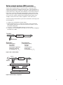
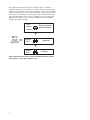
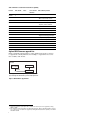
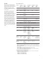
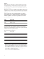
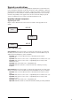
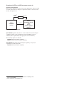
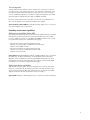
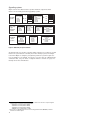
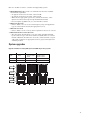
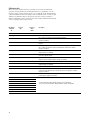
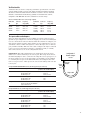
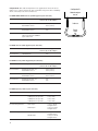
Agilent
Upgrade Guide for the 8510
Vector Network Analyzer
Product Note
85107B, 45 MHz to 50 GHz in coax
85106D with option 001,
45 MHz to 50 GHz in coax,
above 50 GHz in waveguide
8510XF
on-wafer configuration
Table of Contents
3
Vector network analyzer (VNA) overview
5
Agilent 8510 family of products
5
Agilent 8510 network analyzer
6
Agilent 8510 firmware upgrade kits
7
Test sets
8
9
9
9
Upgrading individual components
Upgrading the 8510
10
Upgrading the 8510 to 8530
11
Test set upgrades
11
Expanding measurement capabilities
11
Adding pulse capabilities
11
Adding time domain capabilities
12
Upgrading systems
13
System upgrades
15
Examples of upgrade paths
15
Measurement accessories
16
Calibration kits
17
Verification kits
17
Test port cables and adapters
19
2
Sources
Upgrade considerations
Related literature
Vector network analyzer (VNA) overview
Vector network analyzer (VNA) measurement systems are used to fully
characterize the linear behavior of two port devices or networks. Device
characteristics include the magnitude and phase data of the transmission or
reflection parameters that are required to determine complex impedance, both
resistive and reactive components, shown in Figure 1. A network’s behavior is
linear when (1) a linear change in the input results in a linear change in the
output, and (2) the output, resulting from multiple input signals, is the same
as the sum of the outputs resulting from independent input signals. Some
examples of linear networks are filters, amplifiers, cables and isolators.
A network analyzer measurement system can be divided into four major parts
shown in Figure 2:
1. A signal source providing the incident signal
2. Signal separation devices to separate the incident, reflected and transmitted signals, and then down converts the microwave signals to a lower
intermediate (IF) signal
3. A receiver to attain the IF signal and down convert it to DC
4. A signal processor and display section that processes the data and displays
information on a CRT
Incident
DUT
Transmitted
Reflected
Reflection
Transmission
(Reflected/incident):
Input SWR
Return loss
Input/output impedance
Reflection coefficient
S-Parameters S11 , S 22
(Transmitted/incident):
Gain/loss
Isolation
Insertion phase
Group delay
S-Parameters S21 , S12
Figure 1. Device characterization
Incident
DUT
Source
Transmitted
Reflected
Signal separation
Incident
Reflected
Transmitted
Receiver/Detector
Processor/Display
Figure 2. Network analyzer configuration
3
The Agilent Technologies 8510 network analyzer consists of a family of
compatible products where each part is a separate system component. Each
complete system includes the 8510 network analyzer, a test set, and compatible
sources (measurement accessories are also needed to complete the measurement setup), shown in Figure 3. The frequency range of the measurement system is determined by the test set or the compatible source’s lesser frequency.
Example: if a 50 GHz test set is used with a 20 GHz source, the maximum
frequency measured is 20 GHz.
8510
network
analyzer
Receiver/detector
processor/display
+
8510
VNA
system
=
Signal
separation
Test set
851X
+
Source
8360
Stimulus
Figure 3. 8510 measurement systems are made up of modular components, the 8510
network analyzer, a test set and a compatible source.
4
Agilent 8510 family of products
85106D
Waveguide
+
systems Test set modules
U-band
Combined coax &
Single-sweep
high
performance
systems
V-band
Q-band
W-band
Waveguide
8510XF
85107B
8510SX
8510E
85108A (50 GHZ)
85108A*
85108L
20 GHz
45 MHz
2 GHz 26.5 GHz
50 GHz
75 GHz
110 GHz
* 85108A also available in frequency range of 45 MHz to 20 GHz
Figure 4. 8510 family of system solutions
Agilent 8510 network analyzer
Tables 1 and 2 show the different features of the 8510A, B, and C, hardware
and firmware, respectively.
Table 1. Hardware revision and measurement capability
Product
Firmware revisions
Hardware features
8510A
A.02.00
• Tape drive
8510B
B.03.00 to B.06.54
• Tape drive
8510C
C.06.00 to present
• Large color display
• Internal disk drive
(LIF or DOS file formats)
• 4 S-parameter display
5
Table 2. Firmware revision and measurement capability
Revision
Time domain1
A.02.00
B.03.00
B.03.11
B.04.00
B.05.00
B.05.11
B.06.30
B.06.54
C.06.00
C.06.54
C.07.00
C.07.01
C.07.14
C.07.16
C.08.10
Pulse2
Power domain
limit lines
Other added key features
• Adapter removal calibration
• Direct control of two sources
• Direct control of up to 4 test sets
• 40 GHz test set capability
• Frequency subset calibration
• Lightwave data format
• 50 GHz source/test set compatibility
• Color display
• Support for hardcopy printer plots
• Color printer capability
• Connector compensation
• Y2K compliance
• CRT
• LCD
Agilent 8510 Firmware upgrade kits
Figure 5 diagrams which product to order (numbers shown above arrows)
to upgrade the existing firmware. For example, to upgrade Rev. C.06.54 to
Rev. C.07.XX, order 11575J.
8510C
Rev. C.06.00
Rev. C.06.50
Rev. C.06.54
11575J
11575J
Rev. C.07.XX
Note: Upgrade kit 11575J has Option 010 (time domain) available.
If you currently have time domain, you must order Option 010.
Figure 5. 8510 firmware upgrade kits
1. Time domain capabilities require Option 010 on the 8510. Time domain option can be upgraded by ordering
85012C for 8510C.
2. Pulse capabilities require Option 008 on the 8510 working with either 85110L or 85110A pulsed-RF S-parameter
test set. Pulse option on the 8510 can be upgraded by ordering 85111B for 8510C. Pulse capability is not available
with 8510A or 8510B.
6
Test Sets
The test set in a VNA measurement
system is used to separate the incident, the reflected, and the transmitted
signals. It is also used to convert
the RF signal to IF (intermediate
fre- quency) signal and to pass the IF
to the receiver.
Once signals are separated, their
individual magnitude and phase
differences can be measured. Test
sets are classified into two groups: (1)
one-path transmission or reflection
and (2) two-path S-parameter allowing forward and reverse measurements of a two port device with a
single connection. S-parameter test
sets can be divided into two types: (1)
sampler- based and (2) mixer-based,
shown in Table 3. Sampler-based test
sets require one external source to
provide the RF stimulus. The mixerbased test sets require two external
sources; one to provide the RF stimulus and the other to provide the LO
signal.
Table 3. Family of test sets
Products
Frequency
range (GHz)
type
Test set
(application)
needed
Recommend
RF source1
needed
Recommend
LO source1
(GHz)
Test port
connector2
(GHz)
8511A3
0.045 to 26.5
Frequency
Converter
N/A
N/A
3.5 mm (M)
8511B3
0.045 to 50
Frequency
Converter
N/A
N/A
2.4 mm (F)
8512A
0.400 to 18
Transmission/
Reflection
Obsolete
8513A
0.045 to 26.5
Transmission/
Reflection
Obsolete
8514A
0.500 to 18
S-parameter
Obsolete
8514B
0.045 to 20
S-parameter
Sampler-based
83621B
-----
3.5 mm (M)
(0.045 to 20)
8515A
0.045 to 26.5
S-parameter
Sampler-based
83631B
(0.045 to 26.5)
---------
3.5 mm (M)
8516A
0.045 to 40
S-parameter
Obsolete --- replaced with 8517A
8517A
0.045 to 50
S-parameter
Obsolete --- replaced with 8517B
8517B
0.045 to 50
S-parameter
Sampler-based
83651B
(0.045 to 50)
-----
2.4 mm (M)
85110L
0.045 to 2
Pulsed-RF
S-parameter
Mixer-based
83620B
#001, 004,
008, H80
83620B
#004, 008,
H80
7 mm
85110A
2 to 20
Pulsed-RF
S-parameter
Mixer-based
83622B
#001, 004, 008
[Option H50:
83650B
(0.045 to 50)
#001, 004, 008]
83623L
#004, 008
3.5 mm (M)
85105A4
MM-wave
Controller
33 to 110
(waveguide
bands)
S-parameter
Mixer-based
(waveguide
bands)
83621B
(0.045 to 20)
[Option 050:
83651B
(0.045 to 50)]
83621B
(0.045 to 20)
WR-22 (33 to 50)
WR-19 (40 to 60)
WR-15 (50 to 75)
WR-10 (75 to 110)
8510XF
MM-wave
Subsystem
0.045 to 110
(coaxial)
S-parameter
Mixer-based
(ultrabroadband)
83651B
(0.045 to 50)
83621B
(0.045 to 20)
1 mm (M)
1. Although general purpose 8360 series synthesized sweepers (836x0B) can be used in place of the 8510-dedicated
8360 series synthesized sweepers (836x1B), the following options are typically recommended: Option 004 (rear
panel connectors) and Option 008 (1-Hz frequency resolution). These options are standard in the 8510-dedicated
8360 series synthesized sweepers.
Mixed sources: While mixing synthesized series is acceptable in multiple-source applications, the following areas
must be considered:
• RF source = 8340, LO source = 8340, system performance will be degraded substantially.
• RF source = 8340, LO source = 8360, better system performance
• RF source = 8360, LO source = 8360, faster step frequency measurements. Using the 8340 as either the RF
source or the LO source will more than double the measurement time.
2. All coaxial test port connectors are ruggedized connectors.
3. These test sets provide access to four samplers directly.
4. The following test set modules are available. Two test set modules must be ordered for complete waveguide
S-parameter test set operation for each waveguide band:
• Q85104A test set module (33 GHz to 50 GHz)
• U85104A test set module (40 GHz to 60 GHz)
• V85104A test set module (50 GHz to 75 GHz)
• W85104A test set module (75 GHz to 110 GHz)
7
Sources
The RF or microwave signal source in a VNA measurement system provides
the incident signal used to stimulate the device-under-test (DUT). The DUT
responds by reflecting part of the incident and transmitting the remaining
part. By sweeping the frequency of the source, the frequency response of the
DUT can be determined.
There are two types of sources available; the General Purpose (GP) 8360 series
synthesized sweepers (836x0B) and the 8510-dedicated 8360 series synthesized
sweepers (836x1B). Note: All 8360A synthesizers have been replaced by 8360B
synthesizers.
Dedicated sources, such as the 836x1B shown in Table 4, are optimized
for use in the 8510 network analyzer systems. They are configured without
modulation capabilities or front panel keyboards. These sources include a
1 Hz frequency resolution and rear-panel output connectors.
Table 4. 8510-dedicated sources
Product1
Frequency range
83621B
45 MHz to 20 GHz
83631B
45 MHz to 26.5 GHz
83651B
45 MHz to 50 GHz
For applications that require modulation capabilities, such as pulsed-RF
measurements, the required source is a general purpose 836x0B synthesized
sweeper, shown in Table 5. Order Option 004 to obtain rear panel connectors,
and Option 008 for 1 Hz frequency resolution.
Table 5. 8360 general purpose synthesizers
Product1
Frequency range
83620B
10 MHz to 20 GHz
83622B
2 GHz to 20 GHz
83623B
10 MHz to 20 GHz (high power)
83624B
2 GHz to 20 GHz (high power)
83630B
10 MHz to 26.5 GHz
83640B
10 MHz to 40 GHz
83650B
10 MHz to 50 GHz
1. Although general purpose 8360 series synthesized sweepers (836x0B) can be used in place of the 8510-dedicated
8360 series synthesized sweepers (836x1B), the following options are typically recommended: Option 004 (rear
panel connectors) and Option 008 (1-Hz frequency resolution). These options are standard in the 8510-dedicated
8360 series synthesized sweepers.
Mixed sources: While mixing synthesized series is acceptable in multiple-source applications, the following areas
must be considered:
• RF source = 8340, LO source = 8340, system performance will be degraded substantially.
• RF source = 8340, LO source = 8360, better system performance
• RF source = 8360, LO source = 8360, faster step frequency measurements. Using the 8340 as either the
RF source or the LO source will more than double the measurement time.
8
Upgrade considerations
There are numerous reasons for upgrading the Agilent 8510 system. The 8510
network analyzer maintains excellent performance while adapting to different
measurement requirements such as basic component testing, on-wafer probing,
pulsed device characterization, antenna and RCS (Radar Cross Section) measurements. Depending on the application, the 8510 network analyzer system
can be reconfigured to meet other system measurement needs.
Upgrading individual components
Upgrading the 8510
Figure 6 below illustrates how the 8510A or 8510B can be upgraded to an
8510C.
85103E
8510A
8510C
8510B
85103F
Figure 6. 8510 upgrade paths
Agilent 85103E Upgrades the 8510A to an 8510C by replacing the top unit and
modifying the bottom unit of the 8510A. It includes on-site installation by an
Agilent Customer Engineer (where available).
Option 001 adds a rack modification kit for mounting in an 85043A
system rack
Option 002 adds an 8360 series source compatibility kit for 8517A/B test sets1
Option 003 adds an 8360 series source compatibility kit for 8514/15 and
85110A test sets1
Option 004 adds an 85110L source compatibility kit
Option 010 adds time domain to an 8510A with time domain previously
installed
Agilent 85103F Upgrades the 8510B to an 8510C by replacing the top unit on the
8510B. It includes on-site installation by Customer Engineer (where available).
Option 001 adds a rack modification kit for mounting in an 85043A system
rack
Option 002 adds an 8360 series source compatibility kit for 8517A/B test sets1
Option 003 adds an 8360 series source compatibility kit for 8514/15 and
85110A test sets1
Option 004 adds an 85110L source compatibility kit
Option 010 adds time domain to an 8510B with time domain previously installed
1. Please review order instructions for serial number break.
9
Upgrading the 8510 to the 8530 microwave receiver for
antenna measurements
Figure 7 below illustrates how the 8510C can be upgraded to either an 8530A
or 8530A and 8510C. For example, to upgrade an 8510C to an 8530A, order
85395C with Option 111.
2
85395C
Opt.111
8530A
microwave
receiver
2
8510C
85396A
85395C
8530A
microwave receiver
and
8510C
network analyzer
capability
Figure 7. 8510 to 8530 upgrade paths
Agilent 85395C2 Upgrades any 8510C to an 8530A. Retains network analyzer
capability. Includes on-site installation by Customer Engineer (where
available). Other requirements may apply (such as 8530 firmware).1
The following options are available:
Option 010 adds time domain capability
Option 111 deletes network analyzer capability
Agilent 85396A Adds 8510C Network Analyzer capability to any 8530A
(equivalent to 8530A Option 011).
Option 010 adds time domain capability
1. For additional information, please refer to the Agilent 85395A/B/C and 85396A Upgrade Kits,
literature number 5091-0948E.
2. Requires an 85101C with serial prefix 3936A or lower
10
Test set upgrades
A single 8510 network analyzer can be configured to control up to four test
sets. The operator can switch between test sets, without reconnections, using
front panel controls. This arrangement is often referred to as the multiple
test set configuration. Each test set must be equipped with Option 001 for IF
switching. Other requirements may apply for RF/LO switching.
For more details, please refer to product note 8510-14, Using Multiple Test
Sets with the Agilent 8510C (literature number 5967-5886E).
Agilent 8511A K01 or 08511-60008 Retrofits IF switching (Option 001) to any 8510
test set for multiple test set operations.
Expanding measurement capabilities
Adding pulse capabilities (Option 008)
To perform pulse measurements, the 8510 network analyzer must be retrofitted
with Option 008. The measurement system must include either the 85110L
(0.045 to 2 GHz) or 85110A (2 to 20 GHz) pulsed-RF S-parameter test set and
two synthesizers (high power synthesizers may apply).
• The 85110L requires an 83620B synthesizer with
Options 001/004/008/H80 (for RF) and an 83620B with
Options 004/008/H80 (for LO)
• The 85110A requires an 83622B synthesizer with
Options 001/004/008 (for RF) and an 83623L with
Options 004/008 (for LO)
Agilent 85111B Adds pulsed-RF measurement capability (Option 008) to the 8510C
by adding new circuitry and includes on-site installation by an Customer
Engineer (where available). To perform pulsed-RF measurements, the 8510
with Option 008 must be used with either the 85110L or 85110A Pulsed-RF
S-parameter test set. Other requirements may apply.
Adding time domain capabilities
With the time domain option, data from transmission or reflection measurements are converted from the frequency domain to the time domain via the
inverse Fourier transform. The time domain data are presented on the CRT
display showing the measured parameter value versus time.
Agilent 85012C Adds time domain (Option 010) to an 8510C (customer installed).
11
Upgrading systems
Figure 8 shows the different 8510 systems and their components. This
figure is an excellent guide when upgrading systems.
85106D
Waveguide
systems
Single-sweep
high
performance
systems
33 to 110 GHz
8510C
85105A
83621B
83621B
+
OR
Q-band
U-band
OR
OR
V-band
W-band
0.045 to 110 GHz
8510C
85105A #050
8517B
83621B
83651B
8510E
8510SX
85107B
0.045 to 20 GHz
8510C
8514B
83621B
0.045 to 26.5 GHz
8510C
8515A
83631B
0.045 to 50 GHz
8510C
8517B
83651B
85108L
Pulsed-RF
or CW
systems
85106D #001
0.045 to 2 GHz
8510C
85110L
83620B #H80
83620B #H80
+
OR
OR
OR
Q-band
U-band
V-band
W-band
8510XF
0.045 to 110 GHz
8510C
MM-wave subsystem
83651B
83621B
85108A*
85108A (50 GHz)
2 to 20 GHz
8510C
85110A
83622B
83623L
2 to 50 GHz
8510C
85110A (50 GHz)
83650B
83621B
* 85108A also available in frequency range of 45 MHz to 20 GHz
Figure 8. 8510 family of system solutions
To upgrade from one system to another, simply order the pieces that are needed
in the new system that are currently not in the existing system, an example
is shown in Figure 9. Complete waveguide S-parameter systems require two
test set modules for each band.1 Necessary accessories such as calibration kits,
verification kits, test port cables or adapters2 must be ordered. See pages 17
through 19 for more information.
1. The following test set modules are available. Two test set modules must be ordered for complete waveguide
S-parameter test set operation for each waveguide band:
• Q85104A test set module (33 GHz to 50 GHz)
• U85104A test set module (40 GHz to 60 GHz)
• V85104A test set module (50 GHz to 75 GHz)
• W85104A test set module (75 GHz to 110 GHz)
2. Please refer to the RF & Microwave Test Accessories Catalog (literature number 5964-9527E) on detailed
information on available adapters.
12
Here is a checklist of items to consider when upgrading systems:
1. Which 8510 do I have? The 8510C is recommended for the latest available
measurement capabilities.
• To upgrade an 8510A to an 8510C, order 85103E.
• To upgrade an 8510B to an 8510C, order 85103F.
• Make sure the appropriate options are ordered. For instance, order
Option 010 if the 8510 has previously installed time domain.
• Do I need pulse capabilities? If yes, order 85111B for 8510C.
2. What test set do I need?
• Refer to Table 3 for test set selection. Frequency range and application
type are critical when selecting the appropriate test set.
3. What source do I need?
• Refer to Table 3 for the source(s) that’s required for the test set of choice.
4. What measurement accessories do I need?
• The appropriate measurement accessories will be determined mainly
by the connector type of the device-under-test (DUT). These accessories
include calibration (mechanical or electronic), verification kits, test port
cables and/or adapters as appropriate. Refer to pages 17 through 19 for
available products.
System upgrades
Upgrades available for existing 8510 systems to 8510XF single-sweep systems
Upgrades
from ...
85107B
85109C
85106C
85106C w/ Opt.002
85106D
85106C w/ Opt.001 & 002
85106D w/ Opt.001
85109C w/ Opt.002
... to 85 GHz
E7345A
E7346A
E7347A
... to 110 GHz
E7355A
E7356A
E7357A
8510C
Millimeter
subsystem
83651B
83621B
Customer
owned
equipment
13
Upgrades for 85107B, 85109C
Upgrade consists of two test heads, a millimeter test set controller, an 83621B
for LO source, and rack. It does not include calibration kits or test port cables.
E7345A upgrade to an 8510XF 85 GHz system
E7355A upgrade to an 8510XF 110 GHz system
The following options are available for both upgrades:
Option 005 add 45 MHz to 2 GHz low frequency extension
Option 006 add RF pass thru (provides coupled output of 50 GHz
source for additional test sets. Additional test set(s) must have Option
001 installed.)
Upgrades for 85106C, 85106C with Option 002 (replaced 8350B/83540A with
83621A/B), 85106D
Upgrade consists of two test heads, a millimeter test set controller and an
83651B for RF source. It does not include calibration kits, test port cables
or rack.
E7346A upgrade to an 8510XF 85 GHz system
E7356A upgrade to an 8510XF 110 GHz system
The following options are available for both upgrades:
Option 005 add 45 MHz to 2 GHz low frequency extension
Option 006 add RF pass thru (provides coupled output of 50 GHz
source for additional test sets. Additional test set(s) must have Option
001 installed.)
Upgrades for 85106C with Options 001 and 002 (added 8517B, replaced 83621A/B
with 83651A/B, and replaced 8350B/83540A with 83621A/B),
85106D with Option 001 (added 8517B and replaced 83621B with 83651B),
85109C with Option 002 (replaced 8350B/83540A with 83621A/B)
Upgrade consists of two test heads and a millimeter test set. It does not
include calibration kits, test port cables or rack.
E7347A upgrade to an 8510XF 85 GHz system
E7357A upgrade to an 8510XF 110 GHz system
The following options are available for both upgrades:
Option 005 add 45 MHz to 2 GHz low frequency extension
Option 006 add RF pass thru (provides coupled output of 50 GHz
source for additional test sets. Additional test set(s) must have Option
001 installed.)
14
Examples of upgrade paths
85107B
(45 MHz to 50 GHz)
current system
8510C
8517B
83651B
Upgrade to 85106D waveguide
system to operate in V-band
New equipment needed:
❑ 85105A1 with
Option 0502 millimeterwave test set controller
❑ 83621B synthesizer
(LO source)
❑ V85104A 3 test set
modules (quantity of 2)
❑ V11644A 3
calibration kit
❑ V11645A 3
verification kit
8510C
85105A #050
8517B
83651B
83621B
Figure 10. Upgrading an 85107B 50 GHz system to an 85106D waveguide system to
operate in V-band (or W-band)
Measurement accessories
There are measurement accessories for seven device connector types: 7 mm,
3.5 mm, 2.92 mm, 2.4 mm, 1.85 mm, 1 mm and Type-N. Calibration kits include
standards that are required for vector error correction. Verification kits
include standards used to verify system performance specifications. Test port
return cables extend the ports of the test set and connect to the device under
test. Agilent 85130X adapter sets convert test set ports to the same connector
type (acting as a test port saver) or to a different connector type.
1. Standard 85105A already includes IF switching (Option 001)
2. Option 050 provides a 50 GHz RF source switch. This is necessary in order to operate with the
existing 83651B 50 GHz source and 8517B 50 GHz test set.
3. To operate in W-band, replace all V-band components with W-band.
15
Calibration kits
Error correction requires that the systematic errors in the measurement
system be characterized by measuring known devices (standards) over the
frequency range of interest with the process of calibration. All calibration kits
contain standards used for this purpose. The standards in the 3.5 mm, 2.4 mm
and Type-N calibration kits use the precision slotless connector (PSC-3.5,
PSC-2.4 and PSC-N). Unless otherwise noted all coaxial calibration kits include
connector gauges and a torque wrench.
Mechanical
calibration
kit
Connector
type
Frequency
range
(GHz)
85050B
7 mm
0.045 - 18
Contains open and short circuits, fixed and sliding terminations.
85050C
7 mm
0.045 - 18
Precision kit. Contains standards for TRL calibration, including precision airline.
Also contains open and short circuits and fixed termination.
85050D
7 mm
0.045 - 18
Economy kit. Contains open and short circuits and precision fixed termination.
Gauges not included.
85052B
3.5 mm
0.045 - 26.5
Contains open and short circuits, fixed and sliding terminations and in-series
adapters.
85052C
3.5 mm
0.045 - 26.5
Precision kit. Contains standards for TRL calibration, including precision airlines.
Also contains open and short circuits, fixed terminations and in-series adapters.
Gauges not included.
85052D
3.5 mm
0.045 - 26.5
Economy kit. Contains open and short circuits, precision fixed termination, and in-series
adapters. Gauges not included.
85054B
Type-N
0.045 - 18
Contains open and short circuits, fixed and sliding terminations, in-series adapters
and 7 mm-to-Type-N adapters.
85054D
Type-N
0.045 - 18
Economy kit. Contains open and short circuits, fixed terminations, in-series
adapters and 7 mm-to-Type-N adapters. Gauges not included.
85056A
2.4 mm
0.045 - 50
Contains open and short circuits, fixed and sliding terminations and in-series adapters.
85056D
2.4 mm
0.045 - 50
Economy kit. Contains open and short circuits, fixed terminations and in-series
adapters. Gauges not included.
85056K
2.92/2.4 mm
0.045 - 50
Contains 2.4 mm open and short circuits, fixed loads and 2.92 mm adapters.
85059A
1 mm
0.045 - 110
Broadband coaxial precision calibration kit consists of 1 mm shorts, opens, fixed
loads and in-series adapters. It also includes offset-shorts covering 50 to 110 GHz.
Gauges not included.
11904S
2.92 mm
0.045 - 40
Must be used with Agilent 85056A/D 2.4 mm calibration kit. Includes four 2.92 mm-to2.4 mm adapters. Gauges not included.
X11644A
WR-90
8.2 - 12.4
P11644A
WR-62
12.4 - 18
K11644A
WR-42
18 - 26.5
R11644A
WR-28
26.5 - 40
Q11644A
WR-22
33 - 50
U11644A
WR-19
40 - 60
V11644A
WR-15
50 - 75
W11644A
WR-10
75 - 110
16
Description
Contains standards for TRL calibration. Includes precision waveguide
section, short circuit and fixed or sliding terminations. Gauges not included.
Verification kits
Verification kits are used to verify the performance specifications of an 8510
system. All kits include a precision Zo airline, mismatched airline and fixed
attenuators. Measured data and uncertainties traceable to the U.S. National
Institute of Standards and Technology (NIST) are included with each kit.
Compliance with MIL-STD 45662A is available for an extra charge
Choose a verification kit for each connector type required.
Verification
kit
Connector
type
Frequency
range (GHz)
Verification
kit
Connector
type
Frequency
range (GHz)
85051B
85053B
85055A
85057B
7 mm
3.5 mm
Type-N
2.4 mm
0.045 - 18
0.045 - 26.5
0.045 - 18
0.045 - 50
R11645A
Q11645A
U11645A
V11645A
W11645A
WR-28
WR-22
WR-19
WR-15
WR-10
26.5 - 40
33 - 50
40 - 60
50 - 75
75 - 110
Test port cables and adapters
Test port cables and adapter sets are available for various connector types.
Special test port adapter sets convert the rugged ports of the network analyzer
test set to the desired connector interface. Each kit contains two adapters, one
male and one female. Both the cables and the test port adapters have one special female connector which is designed to connect directly to the 3.5 mm test
port (2.4 mm for 8517B). This side of the cable or adapter can only be connected
to the test set port and cannot be mated to a standard 3.5 mm (or 2.4 mm)
male connector. Choose one of the configurations shown.
Configuration A. This cable arrangement is for applications where the device
under test is connected directly to the test set port. This setup offers the best
mechanical rigidity for device connection. To adapt the test set port (port 1) to
the device under test, choose the appropriate special adapter set. In addition
to converting the test port to the desired interface, these adapters also function as “test port savers” which protect the test set from damage and wear due
to heavy use.
For Agilent 8514B/8515A/85110A test sets (3.5 mm rugged test port connectors)
Cables/adapter
Connector type
(on device side of cable/adapter)
For 3.5 mm devices
85131C semi-rigid cable or
85131E flexible cable
85130D adapter set
3.5 mm (f)
3.5 mm (f )
3.5 mm (m and f)
For 7 mm devices
85132C semi-rigid cable or
85132E flexible cable
85130B adapter set
7 mm
7 mm
7 mm
For Type-N devices
Use 7 mm cables and the 7 mm-to-Type-N
adapters included in the 85054B/D
Type-N calibration kit
Configuration A
Network analyzer
test set
Device
under
test
Test port
adapter
Single cable
For Agilent 8517B test sets (2.4-mm rugged test port connectors)
Cables/adapter
Connector type
(on device side of cable/adapter)
For 2.4 mm devices
85133C semi-rigid cable or
85133E flexible cable
85130G adapter set
2.4 mm (f)
2.4 mm (f )
2.4 mm (m and f)
For 3.5 mm devices
85134C semi-rigid cable or
85134E flexible cable
85130F adapter set
3.5 mm (f)
3.5 mm (f )
3.5 mm (m and f)
For 7 mm devices
85135C semi-rigid cable or
85135E flexible cable
85130E adapter set
7 mm
7 mm
7 mm
17
Configuration B. This cable arrangement is for applications where the device
under test is connected between cable ends. This setup offers more flexibility
when connecting to the device under test.
Configuration B
Network analyzer
test set
For 8514B/8515A/85110A test sets (3.5 mm rugged test port connectors)
Cables/adapter
For 3.5 mm devices
Connector type
(on device side of cable/adapter)
85131D semi-rigid cable set or
85131F flexible cable set
3.5 mm (m and f)
3.5 mm (m and f)
For 7 mm devices
85132D semi-rigid cable set or
85132F flexible cable set
7 mm
7 mm
For Type-N devices
Use 7 mm cables and the 7 mm-to-Type-N
adapters included in the 85054B/D
Type-N calibration kit
For 85110L Test sets (7 mm rugged test port connectors)
Cables/adapter
For 7 mm devices
Connector type
(on device side of cable/adapter)
11857D Cable pair
7 mm
For 8517B Test sets (2.4 mm rugged test port connectors)
Cables/adapters
Connector type
(on device side of cable/adapter)
For 2.4 mm devices
85133D semi-rigid cable set or
85133F flexible cable set
2.4 mm (m and f)
2.4 mm (m and f)
For 3.5 mm devices
85134D semi-rigid cable set or
85134F flexible cable set
3.5 mm (m and f)
3.5 mm (m and f)
For 7 mm devices
85135D semi-rigid cable set or
85135F flexible cable set
7 mm
7 mm
For 8510XF systems (1 mm test port connectors)
Cables/adapters
Connector type
For 1 mm devices
11500I (8.8 cm) test port cable
11500J (16 cm) test port cable
11500K (20 cm) test port cable
11500L (24 cm) test port cable
1 mm (f and f)
1 mm (m and f)
1 mm (m and f)
1 mm (m and f)
For V-band waveguide devices
V281C adapter
1 mm (f) to V-band
waveguide devices
1 mm (m) to V-band
waveguide devices
V281D adapter
For W-band waveguide devices
W281C adapter
W281D adapter
18
1 mm (f) to W-band
waveguide devices
1 mm (m) to W-band
waveguide devices
Cable set
Device
under
test
Related literature
Pub. number
Agilent 8510 Network Analyzer, Color Brochure
Agilent 8510 System Solutions
Agilent 8510 Family Network Analyzer, Configuration Guide
Agilent 8510 Family Network Analyzer, Data Sheet
Agilent 85103C/D Upgrade Packages to the 8510C
Agilent 85395A/B/C and 85396A Upgrade Kits,
(8510 to 8530 upgrades)
Agilent 8360B Series Synthesized Swept Signal Generators,
Data Sheet
5091-8970E
5965-8837E
5091-8967E
5091-8484E
5091-8969E
Product overviews
Agilent 85106D Millimeter-wave Network Analyzer System
Agilent 85108A/L CW/Pulsed Network Analyzer Systems
Agilent 8510XF 110 GHz Single-Sweep Systems
Agilent 85060 Series and 85090 Series Electronic
Calibration Modules and PC Interface
Product notes
Agilent PN 8510-14, Using Multiple Test Sets
with the 8510C
5091-0948E
5964-6162E
5964-4229E
5091-8965E
5965-9888E
5963-3743E
5967-5886E
19
For more information on the 8510
VNA visit:
www.agilent.com/find/8510
www.agilent.com/find/emailupdates
Get the latest information on the products
and applications you select.
Agilent Technologies’ Test and
Measurement Support, Services,
and Assistance
Agilent Technologies aims to maximize
the value you receive, while minimizing
your risk and problems. We strive to
ensure that you get the test and measurement capabilities you paid for and obtain
the support you need. Our extensive support resources and services can help you
choose the right Agilent products for your
applications and apply them successfully.
Every instrument and system we sell has
a global warranty. Support is available for
at least five years beyond the production
life of the product. Two concepts underlie
Agilent's overall support policy: "Our
Promise" and "Your Advantage."
By internet, phone, or fax, get assistance
with all your test and measurement needs.
Our Promise
Our Promise means your Agilent test and
measurement equipment will meet its
advertised performance and functionality.
When you are choosing new equipment,
we will help you with product information,
including realistic performance specifications and practical recommendations from
experienced test engineers. When you
use Agilent equipment, we can verify that
it works properly, help with product operation, and provide basic measurement
assistance for the use of specified capabilities, at no extra cost upon request.
Many self-help tools are available.
Europe:
(tel) (31 20) 547 2323
(fax) (31 20) 547 2390
Your Advantage
Your Advantage means that Agilent offers
a wide range of additional expert test and
measurement services, which you can
purchase according to your unique technical and business needs. Solve problems
efficiently and gain a competitive edge by
contracting with us for calibration, extracost upgrades, out-of-warranty repairs,
and on-site education and training, as
well as design, system integration, project
management, and other professional engineering services. Experienced Agilent
engineers and technicians worldwide can
help you maximize your productivity, optimize the return on investment of your
Agilent instruments and systems, and
obtain dependable measurement accuracy
for the life of those products.
Taiwan:
(tel) 0800 047 866
(fax) 0800 286 331
Online assistance:
www.agilent.com/find/assist
Phone or Fax
United States:
(tel) 800 452 4844
Canada:
(tel) 877 894 4414
(fax) 905 282 6495
China:
(tel) 800 810 0189
(fax) 800 820 2816
Japan:
(tel) (81) 426 56 7832
(fax) (81) 426 56 7840
Korea:
(tel) (82 2) 2004 5004
(fax) (82 2) 2004 5115
Latin America:
(tel) (305) 269 7500
(fax) (305) 269 7599
Other Asia Pacific Countries:
(tel) (65) 6375 8100
(fax) (65) 6836 0252
Email: [email protected]
Product specifications and descriptions
in this document subject to change
without notice.
Copyright © 2002
Agilent Technologies, Inc.
Printed in USA, June 13, 2002
5968-6423E