1
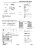
PRECISION SENSITIVE DIGITAL TACHOMETER
INSTAllATION
INSTRUCTIONS
.
Special Instructions for '-SM' &'-SH' Versions
Aetna Engineering Precision Sensitive Digital
Tachometers are premium quality instruments.
Th.ey use "LSI" digital circuitry to provide an
instrument guaranteed accurate to one RPM,
that. never requires calibration, and performs
reliably in the marine environment.
The '-S_' version tachometers are supplied with
a special ratio setting designed to operate from
the signal provided from a "mag-pickup. or other
sensor which receives a particular number of
pulses-per-revolution (PPR) from the rotating
device to be measured. The PPR ratio refers to
the preset number of pulses the tachometer
must detect for each revolution of the apparatus
to be measured. The '-SM' version is rated for
use between 28 and 90 PPR and the '-SH'
version is rated for use between 90 and 255
PPR.
The overc:ill tachometer performance
involves functions beyond the PPR ratio, such as
filter constants and signal sensitivity. Therefore,
the correct version, '-SM' or '-SH' must be used
for the specific PPR ratio desired or satisfactory
performance will not be realized.
The tachometers are available with either Light
Emitting Diode (LED-Model 8402) or Liquid
Crystal Display (LCD-Model 8905) readouts.
The LED is best suited for use in shaded
sunlight while the LCD should be used in
applications where the tachometer will be
exposed to direct unshaded sunlight. Both are
self-illuminated for night viewing.
The tachometers are supplied with a choice of
black or polished stainless steel bezel. The
black bezel tachometer includes a trim ring
which can be optionally used as required to
match existing. instrumentation.
Aetna
tachometers also fit perfectly inside both the
round and square VDO Blue Line cases (contact
us for detailed instructions).
I
Mounting:
Select a mounting location where the tachometer
may be easily read. The front of the tachometer
has a gasketed glass-to-metal seal making it
suitable for use in locations exposed to rain and
spray. It uses only non-ferrous materials so it
can be located in close proximity to a compass
without significantly affecting the compass
(nevertheless, the compass adjustment should
be checked after installation;
particularly
because the removed tachometers may have
been influencing the compass). The unit may be
installed in an existing standard 3-3/8 inch
diameter hole. It will fit holes up to 4 inches
when used with the optional black trim ring. If
placing the tachometer under a protective glass
cover, be sure that it is adequately ventilated to
keep the maximum temperature of the case
below 175 degrees Fahrenheit. Exceeding this
case temperature may damage the tachometer.
Mount the tachometer using the clamp and
hardware provided.
In exposed locations it
should be bedded down with a bead of sealant
behind the flange. Place the tach in the raised
trim ring if it is to be used. If the trim ring is
positioned so that it will collect water, drill a
3/16" drain hole at the lowest point in the ring.
The clamp legs may be bent over or cut off to
accommodate thicker panels.
An O'ring is
included for use as. a centering aid when
installing the unit in 3-3/8 inch holes. If the hole
is tight, roll the O'ring back from the flange then
insert the tach so that the O'ring rolls into the
hole as the tach is inserted. For larger holes an
Oaring type spacer may be made from a length
of appropriate diameter wire.
"
Wiring:
During wiring it is recommended that the
negative battery cable be removed from the
battery or the master switch(es) turned off.
The tachometer has a grounded case and is for
use on negative ground systems only (an
isolated case version is available for isolated or
positive ground use.) Connect the "Ground"
terminal to a point that is connected to the
negative (-) battery terminal.
Connect the "+12V" terminal to a point that is.
energized when the ignition is switched on;
typically a purple wire. In most cases, power
and ground are available by wiring to the
terminals on an adjacent temperature or oil
pressure gauge. A one amp fuse must be
installed in series with the "+" (Pos) wire in order
to enable the internal surge protectorfunction.
To use the Model 8402 on 24 volts connect a 30
ohm, 25 watt resistor (our Model 8924) in series
with the "+12V" tachometer terminal. For 32
volts use a 47 ohm, 25 watt resistor (our Model
8932). Failure to use the appropriate ballast
resistor may damage the Model 8402
tachometer. The "+12V" terminal on the Model
8905 tach. may be safely connected to 12, 24 or
32 volt systems without a ballast resistor.
The "Points" (8ig.) terminal connects the RPM
information signal from the engine to the
tachometer. This connection should be made
using stranded two conductor twisted-shielded
wire.
For multiple stations, two or more
tachometers may be connected in parallel.
Diesel engines have no ignition and therefore
require a tachometer sender to generates the
digital impulses required by the tachometer.
Traditionally a mechanically driven sender was
mounted on the tachometer drive cable fitting on
the engine. Many newer engines do not have
such a fitting and instead use a magnetic pickup.
A "mag.. pickup is a device that senses the
passage of gear teeth in a non-contact manner.
It is screwed into a threaded hole in the gear
housing and adjusted so that the clearance is
approximately one-half turn back from contact
with the gear.
The two sender wires are
connected to the signal and ground terminals at
the tachometer using a twisted/shielded cable.
Connect the two wires from the sender through
the two twisted inner conductors. Connect the
shield to the engine block. Do not connect the
tachometer end of the shield. If the signal is
continued on to another tachometer, carry the
shield connection through but do not connect it
to anything but the engine. Using a single wire
and the engine ground is not recommended and
will yield inferior results.
Diesel Sender Installation:
The Aetna Engineering Models 8910, 8912 and
8922 are magnetically coupled senders which
sense the passage of flywheel gear teeth or
similar items. They generates the electrical
RPM signal used by the tachometer. The 8910
and 8912 are housed in a %" diameter by 16
threads per inch case while the 8922 is
contained in a 5/8" by 18 threads per inch case.
Both the 8912 and 8922 have dual electrical
outputs.
Note that some engines built offshore have
metric sized sender mounting holes. Although
Aetna does not provide metric sized senders,
most metric "mag pickup. senders will
satisfactorily drive Aetna tachometers.
The sender is installed by screwing it into a
threaded hole on the flywheel bell housing or
other housing. It is screwed in until the end
contacts the gear then backed-off one-half turn
and sequredin position with the jam nut. The
sender is connected to the tachometer using two
conductor twisted-shielded wire as previously
described.
This combination of tachometer and sender will
register the engine speed accurately to within +/one RPM when the sender is driven at exactly
the preset number of pulses-per-revolution rated
on the tachometer
Testing:
Reconnect the battery and turn the ignition on.
The display should illuminate and show "0000"
indicating power is reaching the unit. Start the
engine and verify that the display indicates
engine RPM. When the engine is cold and idling
without load the right hand digits may seem to
"jump." This is due to fluctuation in the engine
speed and is pronounced because the readout
displays variations as small as one RPM. The
RPM's should steady when the engine is warmed
and operated above idle under a constant load.
Should the display continue to jump excessively
check engine tuning, look for a fouled injector or
a fuel suction line air leak. Contact the factory
for more suggestions.
\
If the tachometer shows all zeros with the engine
running, check the signal wiring from the engine.
If the tachometer's digits fail to show at all, the
problem is in the power wiring to the tachometer
and not in the signal wiring. If the indicated
RPM is in error, check that the ratio select
switches are set properly.
The tachometer includes special circuitry to
minimize loran interference from the digital
processor.
Nevertheless, if a loran set is
aboard, it should be checked for interference by
obseNing the loran SNR when the ignition is on
without the engine running.
Be sure any
interference isn't from an alarm buzzer or bell. If
interference is detected, check the loran antenna
& ground or install a filter, such as the "MAR-P5"
from Marine Technology (562) 595-6521, in the
+12 volt power and ground leads to the
tachometer.
The tachometer is now ready to use. No
adjustment is ever necessary. The circuftry
employs a piezoelectric crystal to permanently
maintain calibration.
On the Model 8402 the built-in dimmer senses
the ambient light. and adjusts the display
intensity for comfortable viewing.
When
operated in bright light the case will feel warm to
the touch. This is normal and will not damage
the unit provided the case temperature does not
exceed 175 degrees.
The Model 8905 has internal backlighting
provided by solid state lamps that do not require
routine replacement. The 8905 consumes less
than one-half watt and does not create
significant heat.
A special anti-fogging compound is applied to
the inside of the glass during manufacture.
Internal fogging of the glass may be reduced by
removing the ratio switch cap. In cases of
persistent fogging,. contact the factory for
additional help. No routine maintenance of the
tachometer is required. Clean the glass with a
soft cloth, The sensor end of the sender should
be cleaned periodically of any accumulation of
magnetic particles which can shunt the magnetic
sensitivity.
The sender may be tested with an ohmmeter.
Measurement of the resistance on the leads
should be between 100 and 1000 ohms. During
installation, wiring can be verified by temporarily
running a separate wire pair directly from the
sender to the tachometer.
Limited Warranty
Aetna Engineering warrants its tachometers to
be free of defects in material and workmanship
for a period of two years from the date of
purchase as shown on the original consumers
purchase receipt.
Warranty seNice will be provided free of charge
if the unit is delivered to Aetna Engineering
during the warranty period accompanied by
original consumer proof of purchase.
Any
transportation, removal, or reinstallation charges
will be paid by the purchaser whenever incurred
in connection with this warranty. In absence of
proof of purchase receipt, the warranty period
shall be twd years from the date of manufacture.
This warranty does not apply to units subjected
to
misuse,
neglect,
accident,
incorrect
installation wiring, improper installation, water
damage, or units used in violation of the
installation instructions furnished by us. This
warranty
excludes
any
incidental
or
consequential damages connected with failure or
defect in the product.
.
Aetna Engineering
products are not designed, intended or approved
for use on or involving aircraft or in hazardous
locations.
This warranty gives you specific legal rights and
you may have other rights which vary from state
to state.
.
Aetna Digital Tachometers
SWITCH SETTING INSTRUCTIONS
For use by Factory Authorized personnel- Only
V-ersion '-SH'
'-SM'
Version
Switch
PPR
28
29
3J
31
32
33
'34
35
36
37
1
0((
off
off
off
o(f
off
off
off
off
off
2
off
38
0((
of(
39
40
41
42
43
44
45
46
47
48
49
:D
51
52
53
54
55
56
57
53
59
EO
61
62
63
64
65
66
67
63
ffi
70
71
72
73
74
75
76
77
78
79
80
81
82
83
84
85
86
87
88
89
00
0((
off
of(
of(
of(
off
off
off
off
off off
off off
off off
off of(
off off
off off
off of(
off off
off off
off off
off off
off of(
off off
off off
off of(
off off
off off
off oif
off off
off off
off off
off off
off off
off off
off off
off Or)
off on
off on
off on
off on
off on
off on
off on
off on
off on
off on
off on
off on
off on
off on
off on
off on
off on
off on
off on
off on
off on
off on
off on
of( on
off on
off on
3
o(f
off
off
off
on
on
on
on
on
on
on
on
on
on
on
on
on
on
on
on
on
on
on
on
on
on
on
on
on
on
on
on
on
on
on
on
off
off
off
off
off
off
off
off
off
off
off
off
off
off
off
off
off
off
off
off
off
off
off
off
off
off
off
5
4
on on
on on
on on
on on
off off
off off
off off
off off
of( off
off off
off 0((
off off
of( on
off on
off on
of( on
off on
off on
off on
off on
on off
on of(
on off
on off
on off
on off
on off
on off
on on
on on
on on
on on
on on
on on
on on
on on
off off
off off
off off
off off
off off
off off
off off
off off
off on
off on
off on
off on
off on
off on
off on
off on
on off
on off
on off
on off
on off
on off
on off
on off
on on
on on
on on
7
6
on off
on off
on on
on on
off off
0(( off
off on
off on
on of(
on off
on on
on on
off off
off off
off on
off on
on off
on off
on on
on on
off off
of( off
off on
off on
on off
on off
on on
on on
off off
off off
off on
off on
on off
on off
on on
on on
off off
off off
off on
off on
on off
on off
on on
on on
off off
off off
off on
off on
on off
on off
on on
on on
off off
off off
off on
off on
on off
on off
on on
on on
off off
off off
off on
Switch
PPR
Position
8
0((
on
off
on
off
on
0((
on
off
on
off
on
Qff
on
off
on
off
on
off
on
off
on
of(
on
off
on
off
on
off
on
off
on
off
on
off
on
off
on
off
on
off
on
off
on
off
on
off
on
off
on
off
on
off
on
off
on
off
on
off
on
off
on
off
.
91
92
93
94
95
96
97
93
99
100
101
102
103
104
1C6
106
107
100
100
110
111
112
113
114
115
116
117
118
119
120
121
122
123
124
125
126
127
128
129
13J
131
132
133
134
135
136
137
138
133
14)
141
142
143
144
145
146
147
148
149
1:D
151
152
153
2
on
0(( on
0(( on
0(( on
0(( on
0(( on
off on
off on
o(f on
off. . on
off on.
off on
off on
off on
off on
off on
off on
of( on
off on
off on
off on
of( on
off on
off on
off on
off on
off on
off on
off on
off on
off ori
off on
off on
off on
off on
off on
off on
on off
on off
on off
on off
on off
on off
on off
on off
on off
on off
on off
on off
on off
on off
on off
on off
on off
on off
on off
on off
on off
on off
on off
on off
on off
on off
1
off
3
off
off
of(
0((
off
on
on
on
on
on
on
on
on
on
on
on
on
on
on
on
on
on
on
on
on
on
on
on
on
on
on
on
on
on
on
on
on
off
off
off
off
off.
off
off
off
off
off
off
off
off
off
off
off
off
off
off
off
off
off
off
off
off
off
4
on
on
on
on
on
of(
of(
off
off
off
off
off
of(
off
off
of(
off
off
off
off
off
on
on
on
on
on
on
on
on
on
on
on
on
on
on
on
on
off
off
off
off
off
off
off
off
off
off
off
off
off
off
off
off
on
on
on
on
on
on
on
on
on
on
Position
5
on
on
on
on
on
off
0((
off
off
off
0((
off
off
on
on
on
on
on
on
on
on
off
off
off
of(
off
off
off
off
on
on
on
on
on
on
on
on
off
off
off
off
off
off
off
off
on
on
on
on
on
on
on
on
off
off
off
off
off
off
off
off
on
on
7
on
of(
of(
on
on
off
off
on
on
off
on of(
on on
on on
off off
off off
off on
off on
on off
on off
on on
on on
off off
of( off
of( on
off on
on off
on off
on on
on on
off off
off off
off on
off on
on off
on off
on on
on on
off off
off off
off cn
off on
on off
on off
on on
on on
Qff off
off off
off on
off on
on off
on off
on on
on on
off off
off of(
off on
of( on
on off
on off
on on
on on
off off
off off
6
off
on
on
on
on
off
off
off
off
on
8
on
0((
on
off
on
of(
on
0((
on
0((
on
off
on
off
on
off
on
off
on
off
on
off
on
off
on
off
on
off
on
off
on
off
on
off
on
off
on
off
on
off
on
off
on
off
on
off
on
off
on
off
on
of(
on
off
on
off
on
off
on
off
on
off
on
Aetna Digital Tachometers
SWITCH SETTING
INSTRUCTIONS
For use by Factory Authorized Personnel
'-SH'
Version
154
155
156
157
158
.159
100
161
162
163
164
165
166
167
168
169
170
171
172
173
174
175
176
177
178
179
180
181
182
183
184
185
186
187
188
100
100
191
192
193
194
195
196
197
100
100
2!JO
2!J1
2!J2
2!J3
204
1
on
on
on
on
on
on
on
on
on
on
on
on
on
on
on
on
on
on
on
on
on
on
on
on
on
on
on
on
on
on
on
on
on
on
on
on
on
on
on
on
on
on
on
on
on
on
on
on
on
on
on
4
3
2
off off on
off off on
off off on
off off on
off off on
off off on
off on off
off on off
off on off
off on off
off on off
off on off
off on off
off on off
off on off
off on off
off on off
off .on off
off on off
off on off
off on off
off on off
off on on
off on on
off on on
off on on
off on on
off on on
off on on
off on on
off on on
off on on
off on on
off on on
off on on
off on on
off on on
off on on
on off off
on off off
on off off
on off off
on off off
on off off
on off off
on off off
on off off
on off off
on off off
on off off
on off off
5
on
on
on
on
on
on
off
off
off
off
off
off
off
off
on
on
on
on
on
on
on
on
off
off
off
off
off
off
off
off
on
on
on
on
on
on
on
on
off
off
off
off
off
off
off
off
on
on
on
on
on
6
off
off
on
on
on
on
off
off
off
off
on
on
on
on
off
off
off
off
on
on
on
on
off
off
off
off
on
on
on
on
off
off
off
off
on
on
on
on
off
off
off
off
on
on
on
on
off
off
off
off
on
Switch
PPR
Switch Position
PPR
7
on
on
off
off
on
on
off
off
on
on
off
off
on
on
off
off
on
on
off
off
on
on
off
off
on
on
off
off
on
on
off
off
on
on
off
off
on
on
off
off
on
on
off
off
on
on
off
off
on
on
off
8
off
on
off
on
off
on
off
on
off
on
off
on
off
on
off
on
off
on
off
on
off
on
off
on
off
on
off
on
off
on
off
on
off
on
off
on
off
on
off
on
off
on
off
on
off
on
off
on
off
on
off
205
206
2!J7
200
200
210
211
212
213
214
215
216
217
218
219
22!J
221
222
223
224
225
226
227
228
229
23J
- 231
232
233
234
235
236
237
238
239
240
241
242
243
244
245
246
247
248
249
2f()
251
252
253
254
255
Only
1
on
on
on
on
on
on
on
on
on
on
.on
on
on
on
on
on
on
on
on
on
on
on
on
on
on
on
on
on
on
on
on
on
on
on
on
on
on
on
on
on
on
on
on
on
on
on
on
on
on
on
on
2"
on
on
on
on
on
on
on
on
on
on
on
on
on
on
on
on
on
on
on
on
on
on
on
on
on
on
on
on
on
on
. on
on
on
on
on
on
on
on
on
on
on
on
on
. on
on
on
on
on
on
on
on
3
off
off
off
off
off
off
off
off
off
off
off
off
off
off
off
off
off
off
off
on
on
on
on
on
on
on
on
on
on
on
on
on
on
on
on
on
on
on
on
on
on
on
on
on
on
on
on
on
on
on
on
4
off
off
off
on
on
on
on
on
on
on
on
on
on
on
on
on
on
on
on
off
off
off
off
off
off
off
off
off
off
off
off
off
off
off
off
on
on
on
on
on
on
on
on
on
on
on
on
on
on
on
on
Position
5
on
on
on
off
off
off
off
off
off
off
off
on
on
on
on
on
on
on
on
off
off
off
off
off
off
off
off
on
on
on
on
on
on
on
on
off
off
off
off
off
off
off
off
on
on
on
onon
on
on
on
6
on
on
on
off
off
off
off
on
on
on
on
off
off
off
off
on
on
on
on
off
off
off
off
on
on,
on
on
off
off
off
off
on
on
on
on
off
off
off
off
on
on
on
on
off
off
off
off
on
on
on
on.
7
off
on
on
off
off
on
on
off
off
on
on
off
off
on
on
off
off
on
on
off
off
on
on
off
off
on
on
off
off
on
on
off
off
on
on
off
off
on
on
off
off
on
on
off
off
on
on
off
off
on
on
8
on
off
on
off
on
off
on
off
on
off
on
off
on
off
on
off
on
off
on
off
on
off
on
off
on
off
on
off
on
off
on
off
on
off
on
off
on
off
on
off
on
off
on
off
on
off
on
off
on
off
on
Procedure: Position the switches according to the table using a thin stylus such as the metal
1Ir .froma all point pen. Care should be taken to use only moderate pressure in actuating the
mdlvldual sWitches to avoid damaging them. Use of plenty of light and magnification can be
helpful. Switch #1 is on the left, #8 on the right; up is on and down is off.