1
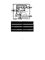
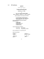
UPS OPERATING INSTRUCTIONS PROTECT 1. PROTECT 1.100 PROTECT 1.150 PROTECT 1.200 2 Thank you for deciding to purchase the PROTECT 1. UPS from AEG Power Supply Systems. The following safety instructions are an important part of the operating instructions are will protect you against problems from operating errors and possible dangers. Please read these instructions carefully prior to commissioning! 3 1 Notes on these Operating Instructions Duty to provide information These operating instructions will help you to install and operate the Uninterruptible Power Supply (UPS), PROTECT 1.100, PROTECT 1.150 or PROTECT 1.200 as well as the corresponding external battery units PROTECT 1.100 BP or PROTECT 1.BP20, all referred to as PROTECT 1 in the following, safely and correctly. These operating instructions contain important information for avoiding dangers. Please read these instructions carefully prior to commissioning! These operating instructions are an integral part of PROTECT 1. The owner of this unit is obliged to communicate the full content of these operating instructions to all personnel transporting or starting the PROTECT 1 or performing maintenance or any other work on the unit. Validity These operating instructions comply with the current technical specifications of PROTECT 1. at the time of publication. The contents do not constitute a subject matter of the contract, but serve for information purposes only. Warranty and liability We reserve the right to alter any specifications given in these operating instructions, especially with regard to technical data and operation. Claims in connection with supplied goods must be submitted within eight days of receiving the goods, along with the packing slip. Subsequent claims cannot be considered. The warranty does not apply for damage caused by noncompliance with these instructions (such damage also includes damage to the warranty seal). AEG will accept no liability for 4 consequential damage. AEG will rescind all obligations such as warranty agreements, service contracts, etc. entered into by AEG or its representatives without prior notice in the event of maintenance and repair work being carried out with anything other than original AEG parts or spare parts purchased from AEG. Handling PROTECT 1. is designed and constructed so that all necessary steps for start-up and operation can be performed without any internal manipulation of the unit. Maintenance and repair work may only be performed by trained and qualified personnel. Illustrations are provided to clarify and facilitate certain steps. If danger to personnel and the unit cannot be ruled out in the case of certain work, it is highlighted accordingly by pictographs explained in the safety regulations of chapter 3. Hotline If you still have questions after having read these operating instructions, please contact your dealer or our hotline: Tel: +49 (0)180 5 234 787 Fax: +49 (0)180 5 234 789 Internet: www.aegpss.de Copyright No part of these operating instructions may be transmitted, reproduced and/or copied by any electronic or mechanical means without the express prior written permission of AEG. © Copyright AEG 2007. All rights reserved. 5 Table of Contents 1 2 Notes on these Operating Instructions .............................4 General Information ..........................................................8 2.1 Technology ................................................................8 2.2 System Description..................................................10 2.3 Technical data .........................................................12 3 Safety Regulations..........................................................16 3.1 Important Instructions and Explanations .................16 3.2 Accident Prevention Regulations ............................16 3.3 Qualified Personnel .................................................17 3.4 Safety Instructions for PROTECT 1. .......................17 3.5 CE certificate ...........................................................21 4 Set-up..............................................................................22 4.1 Unpacking and inspection .......................................22 4.2 Transport to installation site.....................................23 4.3 Set-Up......................................................................23 4.4 Overview: Connections, Operating / Display Elements.....................................................25 4.4.1 Front view...........................................................25 4.4.2 Display ...............................................................26 4.4.3 Rear view (connections): ...................................27 5 Electrical connection .......................................................29 5.1 Safety of personnel..................................................30 5.2 Mains connection (general) .....................................30 5.2.1 Checklist for cable connections .........................30 5.2.2 Connection Cross-Sections and Fuse Protection ...........................................................31 5.3 Mains connection.....................................................32 5.3.1 Preparation for the three-phase mains connection ....................................................32 5.3.2 Connection of the three-phase input mains voltage .....................................................32 5.3.3 Preparation of the output cabling.......................33 5.3.4 Connection of the loads .....................................34 5.4 Connection of external battery modules..................34 5.4.1 Connection of the battery cubicle PROTECT 1.100 BP ..........................................35 6 5.4.2 Connection of the battery cubicle PROTECT 1. BP20 ..................................................................36 5.5 Mechanical blocking of the PROTECT 1.................37 6 Start-Up...........................................................................38 6.1 Operating modes .....................................................39 6.1.1 Normal operation ...............................................39 6.1.2 Battery Operation / Autonomous Operation ......40 6.1.3 Bypass operation ...............................................42 6.1.4 Manual bypass...................................................44 6.1.5 Unit overload......................................................45 7 Interfaces and communication........................................46 7.1 Computer interface RS232......................................46 7.2 Communication Slot ................................................46 7.3 Shutdown and UPS Management Software............46 8 Displays and troubleshooting..........................................48 8.1.1 Signalling ...........................................................48 8.1.2 Overview table of LED displays / acoustic warning signals ..................................................50 8.2 Faults.......................................................................52 8.2.1 Error Messages..................................................52 9 Parallel Operation ...........................................................54 9.1 Principle of Operation ..............................................54 9.2 Set-up / connection of parallel operation board ......55 9.3 Operation of the UPS in a parallel system ..............57 9.3.1 Start-Up..............................................................57 9.3.2 Changes to the parallel system .........................59 10 Maintenance ...................................................................60 10.1 Charging the Battery ...............................................60 10.2 Checks.....................................................................60 10.2.1 Visual check.......................................................60 10.2.2 Checking the battery..........................................61 10.2.3 Fan check ..........................................................61 11 Storage, Dismantling and Disposal.................................62 11.1 Storage ....................................................................62 11.2 Dismantling..............................................................62 11.3 Disposal...................................................................62 12 List of terms ....................................................................63 12.1 Technical terminology .............................................63 7 2 General Information 2.1 Technology i PROTECT 1. is an Uninterruptible Power Supply (UPS) for essential loads such as small data centres, servers, network components, telecommunications equipment and similar units. It consists of: ♦ Mains filter with overvoltage protection (appliance protection / class D) and mains energy backfeed protection ♦ Rectifier section with PFC logic (power factor correction unit) ♦ Separate battery charger with switch mode power supply technology ♦ IGBT inverter for continuous supply of connected loads with sinusoidal AC voltage ♦ Automatic electronic bypass (SBS) as additional, passive redundancy SBS = Static Bypass Switch ♦ Manual bypass for maintenance and service purposes (with automatic SBS activation upon actuation) ♦ Control unit on the basis of digital signal processor technology 8 Manueller Service - Bypass Elektron. Verriegelung EUE PFC Netzfilter Last Netz Filter Gleichrichter Wechselrichter DC/ DC Booster Ladegleichrichter DSP Regelungslogik Komponentendarstellung Batteriesystem (extern) RS 232 SNMP Manual service bypass Electronic locking SBS PFC Mains filter Load Mains Filter Rectifier Inverter DC/DC booster Battery charger DSP control logic Component diagram Battery system (external) RS 232 SNMP 9 2.2 System Description The UPS is connected between the public utility mains and the loads to be protected. The power section of the rectifier converts the mains voltage to DC voltage for supplying the inverter. The circuit technology used (PFC) enables sinusoidal current consumption and therefore operation with little system disturbance. A separate, second rectifier (charging REC set up using switch mode power supply technology) is responsible for charging or trickle-charging the battery connected in the intermediate circuit. The configuration of this charging REC means the harmonic content of the charging current for the battery is almost zero, which increases the service life of the battery even more. The inverter is responsible for converting the DC voltage into a sinusoidal output voltage. A microprocessor-driven control based on a pulse-width modulation (PWM) guarantees, in conjunction with digital signal processor technology and extremely fast pulsating IGBT power semiconductors of the inverter, a voltage system of the highest quality and availability on the secured busbar. In the event of mains faults (such as e.g. current failures), the voltage continues to be supplied from the inverter to the load without any interruption. From this point onwards, the inverter draws its power from the battery instead of the rectifier. Since no switching operations are necessary, there is no interruption in the supply to the load. The automatic electronic bypass serves to increase the reliability of the supply further, especially in the case of individual systems. It switches the public mains directly through to the load without any interruption, e.g. when there is an inverter malfunction. As a result, the automatic bypass represents an extra passive redundancy for the load. An integrated, manually operated bypass unit ensures an uninterrupted supply to the connected loads in the case of maintenance and/or service work. The internal electronic part (with the exception of the metal-clad manual bypass) can be disconnected via the mains input miniature circuit breakers. 10 The greatest possible supply reliability of connected loads is attained by the parallel connection of up to max. three PROTECT 1. UPS systems. The n+x technology thus guarantees maximum reliability through up to double active redundancy on the one hand as well as on the other hand the possibility of increased power with simple redundancy or even only higher UPS power without any redundancy. The relationship between the available output power and the degree of active redundancy can be seen in the following overview: Parallel system with PROTECT 1.100 Available power Active redundancy degree Number of UPS units 1 2 3 0 10 kVA 20 kVA 30 kVA 1 --- 10 kVA 20 kVA 2 --- --- 10 kVA Parallel system with PROTECT 1.150 Available power Active redundancy degree Number of UPS units 1 2 3 0 15 kVA 30 kVA 45 kVA 1 --- 15 kVA 30 kVA 2 --- --- 15 kVA Parallel system with PROTECT 1.200 Available power Active redundancy degree Number of UPS units 1 2 3 0 20 kVA 40 kVA 60 kVA 1 --- 20 kVA 40 kVA 2 --- --- 20 kVA 11 2.3 Technical Data Type rating PROTECT 1.100 10000 VA (cos ϕ = 0.7 ind.) 7000 W PROTECT 1.150 15000 VA (cos ϕ = 0.7 ind.) 10500 W PROTECT 1.200 20000 VA (cos ϕ = 0.7 ind.) 14000 W UPS input 3ph~ / N / PE Rated connection voltage Voltage range without battery operation 400 V/ 230 VAC 304 VAC – 478 VAC ± 3 % (rectifier) 176 VAC – 261 VAC VAC ± 3 % (bypass) Frequency 50 Hz / 60 Hz (autom. detection) Frequency tolerance range ± 4 Hz Current consumption at full load (max.) PROTECT 1.100 13 A (3ph~) / 46 A (bypass) PROTECT 1.150 19 A (3ph~) / 68 A (bypass) PROTECT 1.200 25 A (3ph~) / 91 A (bypass) System disturbance factor λ ≥ 0.95 UPS output Nominal voltage output Nominal frequency Type of voltage Crest factor 220 / 230 / 240 VAC ± 1% (configuration via “CompuWatch” software ) 50 Hz / 60 Hz ± 0.1% (dependent on mains frequency) Sine, distortion ≤ 2% THD (linear load) ≤ 6% THD (non-linear load) 3:1 12 Overload behaviour with mains supply Overload behaviour with battery operation Short-circuit behaviour Up to 105% continuous; > 105% – < 130% for 10 min. 130% for 1 s Following this, automatic, uninterrupted switchover to integrated bypass (SBS). Switch-off after 1 min if overload continues to be present. (Switch back if overload decreases = load < 90%) Up to 105% continuous; > 105% for 10 s 2.5 x IN for 100 ms Battery Standby times with external standard battery units Standby times (full load / half load) [min.] PROTECT 1.100 PROTECT 1.150 PROTECT 1.200 1 x PROTECT 1.100 BP 16 / 42 --- --- 5h 2 x PROTECT 1.100 BP 42 / 97 --- --- 7h --- 10h Coupled battery cubicles Recharging time to 90% capacity 3 x PROTECT 1.100 BP 60 / 134 --- 1 x PROTECT 1. BP 20 19 / 47 10 / 29 6 / 19 2 x PROTECT 1. BP 20 47 / 103 29 / 68 19 / 47 9h 3 x PROTECT 1. BP 20 78 / 77 47 / 103 34 / 62 13h 4 x PROTECT 1. BP 20 103 / 243 68 / 153 47 / 103 18h 5 x PROTECT 1. BP 20 138 / 312 85 / 202 63 / 138 24h 5h Nominal DC voltage (intermediate circuit): 240 VDC Trickle charge voltage: 274 VDC ± 1% Battery charging current (max.): 4.2 ADC Type Sealed, maintenance-free PROTECT 1.100 BP 2x20 blocks 12V 9Ah, e.g. CSB HR 1234WF2 PROTECT 1.BP20 1x20 blocks 12V 20Ah, e.g. Panasonic LC-X1220P 13 Communication Interfaces Shutdown software on CD RS232 Sub-D (9-pin) Additionally: Communication slot for expansions (e.g. AS/400 / USB / remote signal indicator / SNMP, …) “CompuWatch” for all common operating systems, e.g. Windows, Linux, Mac, Unix, FreeBSD, Novell, Sun General data Classification Full load efficiency ( AC-AC / DC-AC ) Inherent noise (1m distance) PROTECT 1.100 PROTECT 1.150 PROTECT 1.200 Cooling type Operating temperature range Storage temperature range Relative humidity Site altitude VFI SS 111 acc. to IEC 62040–3 Sustained transformer technology > 90% / > 88% < 55 dB(A) < 60 dB(A) < 60 dB(A) Forced air cooling through variable-speed fans 0°C to +40°C Recommended: +15°C to +25°C (due to battery system) 0°C to +40°C < 95% (without condensation) Up to 1000 m at nominal output Use more than 1000 m above sea level results in the following reduction in output power: 14 Height(m) 1000 Output power Housing colour: Weight: PROTECT 1. 100 PROTECT 1. 150 PROTECT 1. 200 PROTECT 1. 100 BP PROTECT 1. BP20 Dimensions W x H x D: PROTECT 1.100/1.150/1.200 PROTECT 1.100 BP PROTECT 1. BP 20 100% 1500 2000 2500 3000 95% 90% 85% 80% Blackline 39 kg 55 kg 55 kg 135 kg 170 kg 260 mm x 717 mm x 670 mm 260 mm x 717 mm x 670 mm 260 mm x 717 mm x 810 mm Directives The PROTECT 1. meets the product standard EN 50091. The CE mark on the unit confirms compliance with the EC outline directives for 73/23 EEC – Low voltage and for 89/336 EEC – Electromagnetic compatibility if the installation instructions described in the operating instructions are observed. For 73/23 EEC low-voltage directive reference number EN 62040-1-1 : 2003 For 89/336 EMC directive reference number EN 50091-2 : 1995 EN 61000-3-2 : 1995 EN 61000-3-3 : 1995 i Warning: This is a product for industrial and commercial use in the second environment – to prevent malfunctions, restrictions on the installation or additional measures may be required. 15 3 Safety Regulations 3.1 Important Instructions and Explanations The instructions for operation and maintenance, as well as the following safety regulations must be complied with to ensure the safety of personnel as well as the continued availability of the unit. All personnel installing/dismantling, starting up, operating or servicing the units must be familiar with and observe these safety regulations. Only trained and qualified personnel may perform the work described, using tools, equipment, test equipment and materials intended for the purpose and in perfect working condition. Important instructions are emphasized by the words “Caution”, “Attention”, “Note” and indented text. Caution This symbol identifies all working and operational procedures requiring absolute compliance to avoid any danger to persons. Attention This symbol identifies all working and operational procedures requiring absolute compliance to prevent any damage, irreparable or otherwise, to the unit and its components. i 3.2 Note This symbol identifies technical requirements and additional information requiring the operator's attention. Accident Prevention Regulations Compliance with the accident prevention regulations valid in the respective country of use and the general safety regulations in accordance with IEC 364 is mandatory. The following safety rules must be observed prior to performing any work on the PROTECT 1.: ♦ Disconnect the unit from the power supply ♦ Secure the unit against being switched back on 16 ♦ Verify that the unit is disconnected from the power supply ♦ Earth and short-circuit the unit ♦ Provide protection by covers or barriers for any neighbouring live parts 3.3 Qualified Personnel The PROTECT 1. may only be transported, installed, connected and serviced by qualified personnel who are familiar with the pertinent safety and installation regulations. All work performed must be inspected by responsible expert personnel. The qualified personnel must be authorised by the responsible safety officer of the installation to perform the work required. Qualified personnel is defined as personnel ♦ having completed training and gained experience in the respective field, ♦ familiar with the pertinent standards, rules and regulations and accident prevention regulations, ♦ having received instruction on the mode of operation and operating conditions of the PROTECT 1., ♦ capable of recognising and preventing dangers. Regulations and definitions for qualified personnel can be found in DIN 57105/VDE 0105 Part 1. 3.4 Safety Instructions for PROTECT 1. The UPS is live, and the voltage can be dangerous. The unit may only be installed and if necessary opened by trained and qualified personnel. Repairs may only be carried out by qualified customer service staff! The output can be live, even when the UPS is not connected to the mains supply! For health and safety reasons, the unit must be earthed correctly! 17 The PROTECT 1. may only be operated with or connected to a three-phase power system with protective grounding using a mains connection cable with PE conductor that has been tested according to German standards (VDE). Risk of burning! The battery has powerful short-circuit currents. Incorrect connection or isolation faults can lead to melting of the plug connections, sparking potential and severe burns! The unit has a warning signal that sounds when the battery voltage of PROTECT 1. is exhausted or when the UPS is not working in its normal mode (see also chapter 6.1 "Signalling”, page 47ff and the following). Observe the following safety instructions to ensure permanent operational safety of and safe work with the UPS and the battery modules (special accessories): ♦ Do not dismantle the UPS! (The UPS does not contain any parts that require regular maintenance. Bear in mind that the warranty will be invalidated if the unit is opened!) ♦ Do not install the unit in direct sunshine or in close proximity of heaters! ♦ The unit is designed to be installed inside in heated rooms. Never install the housing in the vicinity of water or in an excessively damp environment! ♦ Condensation may occur if the UPS is brought from a cold environment into the room where it is to be installed. The UPS must be absolutely dry prior to start-up. As a result, leave it to acclimate for at least two hours. ♦ Never connect the mains input and the UPS output! ♦ Ensure that no fluids or foreign bodies can penetrate the housing! ♦ Do not block the air vents of the unit! Make sure, for example, that children do not insert any objects in the ventilation openings! 18 ♦ Do not connect household appliances such as hairdryers to the UPS! Also take care when working with motor loads. It is essential to avoid back-feeding the inverter, e.g. if the load is intermittently operated in regenerative mode. Danger! Electric shocks! Even after the mains voltage has been disconnected, the components within the UPS remain connected to the battery and can thus cause electric shocks. It is therefore imperative to disconnect the battery circuit before carrying out any maintenance or repair work! If it is necessary to replace the battery or carry out maintenance work, this must be done by or under the supervision of a specialist familiar with batteries and the necessary safety precautions! Only authorized persons are allowed in the vicinity of the batteries! When replacing the batteries, the following must be observed: Only ever use identical, maintenance-free sealed lead batteries with the same data as the original batteries. Danger! Explosive! Never throw batteries into open fire. Never open or damage batteries. (Electrolyte may leak out and damage skin and eyes. It may be toxic!) Batteries can cause electric shocks and high short-circuit currents. Therefore, take the following safety precautions when working with batteries: ♦ Take off watches, rings and other metallic objects! ♦ Only use tools with insulated handles! 19 i Avoid using multiple outlet adapters with a central on/off switch as protection against uncontrolled load switch-off as well as for avoiding peak inrush currents. Switch OFF the UPS using its main switch if you do not intend to use it for some time. PROTECT 1. must be switched off every evening if the electricity supply in your company is switched off every night. Otherwise, the battery will be discharged. Frequent and exhaustive discharging of the battery leads to a shorter service life of the battery and should therefore be avoided! For personal safety reasons, never switch on the main switch when the mains connector of PROTECT 1. is disconnected! 20 3.5 CE Certificate 21 4 4.1 Set-up Unpacking and Inspection The unit has been completely checked and inspected. Although the unit has been packed and shipped with the usual care, transport damage cannot be completely excluded. i Any claims due to transport damage must always be asserted against the transport company! Check the shipping container for damage on arrival. If necessary, ask the transport company to check the goods and make a record of the damage in the presence of the transport company employee and report the damage to the AEG representative or dealer within eight days of delivery. Check that the delivery is complete: ♦ PROTECT 1. with 10000, 15000 or 20000 VA ♦ Cable clamping unit ♦ Special battery connection cable (PROTECT 1.100) ♦ 25-pin parallel operation cable ♦ RS232 communication cable ♦ Management software “CompuWatch” on CD ♦ Operating instructions Delivery of external battery modules includes: ♦ External battery unit ♦ Battery connection cable ♦ Battery fuses and terminal connectors (PROTECT 1. BP20) Please contact our hotline (see page 5) in case of any discrepancy. The original packaging provides effective protection against mechanical shocks and should be retained so the unit can be transported safely later on. 22 Please keep plastic packaging bags away from babies and children in order to safeguard against suffocation accidents. Handle the components with care. Please take into account the weight. It may be necessary to engage the help of a second person. 4.2 Transport to Installation Site The PROTECT 1. is equipped with transport rolls for easy transport to the intended installation site. It is recommended to install the UPS where: ♦ The connection work can be conveniently carried out; ♦ There is enough space for proper operation and, if necessary, for periodic and extraordinary maintenance work; in this regard, the connection cables should be long enough to move the UPS (to open the UPS if necessary) without having to switch it off. ♦ The use of an external manual bypass is recommended ♦ The UPS is protected against external atmospheric influences; ♦ The humidity and the ambient temperature are within the limits; ♦ The fire protection standards are observed. The battery service life strongly depends on the ambient temperature. Ambient temperatures between+ 15° and + 25°C are optimum. Attention! Only transport the PROTECT 1. in an upright position! Never tilt or cant it; avoid displacing the centre of gravity! Make sure that no magnetic storage media are stored and/or operated close to PROTECT 1. 4.3 Set-Up Note the following points when setting up the UPS system and its external battery units (special accessories): 23 ♦ The contact surface must be smooth and level. It must also be sufficiently strong and sturdy to avoid vibration and shocks. ♦ Make sure that the mounting is able to support the weight, especially in conjunction with external battery units (special accessories). ♦ Set up the units so that adequate air circulation is assured. There must be at least 200 mm clearance behind the rear fans for ventilation purposes. Do not block the intake openings on the front and, if present, on the side of the unit. There must be a gap of at least 50 mm here. ♦ External battery units must be placed on the side of the UPS system. To ensure the greatest possible mechanical stability, do not place the external battery unit(s) above or below the UPS system. ♦ Avoid extreme temperatures! We recommend an ambient temperature from 15°C to 25°C in order to maximize the service life of the batteries. Do not expose the units to direct sunlight or operate them close to other heat sources such as radiators. ♦ Protect the units against external effects (in particular moisture and dust). In this regard, please also refer to the instructions in chapter 3, page 16 in these operating instructions. If you transport the unit from a cold room into a warm one, or if the room temperature suddenly drops, then condensation may form inside the unit. To avoid any damage due to condensation, let the unit acclimate for 2 hours before you switch it on. 24 4.4 Overview: Connections, Operating / Display Elements 4.4.1 Front view PROTECT 1.100 PROTECT 1.150 PROTECT 1.100BP PROTECT 1.BP20 25 PROTECT 1.200 4.4.2 Display 12 11 10 9 8 7 3 6 4 5 2 1. 2. 3. 4. 5. 6. 7 – 11. 7. 8. 9. 10. 11. 12. 1 OFF pushbutton ON pushbutton / alarm off Orange-coloured Bypass LED Green Inverter LED Orange-coloured Battery LED Green Line LED Bar graph LED (7-10 green, 11 orange-coloured) for UPS capacity utilisation or remaining battery capacity LED load (0-35%) battery capacity (96-100%) LED load (36-55%) battery capacity (76-95%) LED load (56-75%) battery capacity (51-75%) LED load (76-95%) battery capacity (26-50%) LED load (96-105%) battery capacity (0-25%) Red Fault LED A detailed explanation of the displays is found on page 48ff. 26 4.4.3 Rear view (connections): PROTECT 1.100 8 7 6 13 5 11 2 3 11 10 9 4 1.1 1.2 1.3 1 N L1 L2 L3 JP1 JP2 L N PROTECT 1.150 / 1.200 6 6 13 12 11 7 5 11 10 9 8 2 1 1.1 3 N L1 L2 L3 27 1.3 4 + - L N 1.2 JP1 JP2 Explanations: 1. Connection terminal cover for mains/UPS input (1.1) and output (1.3), additional pair of terminals for setting individual or parallel operation (1.2); Battery connection terminals (PROTECT 1.150 / 1.200) 2. Mains input miniature circuit breaker 3. Manual bypass switch 4. Socket for external battery module (PROTECT 1.100) or connection terminals for external battery (PROTECT 1.150/1.200) 5. Connectors for parallel operation 6. Fan (attention: Leave at least 10 cm clearance behind fan for unobstructed airflow out!) 7. Communication slot for optional expansion boards: SNMP, AS/400, USB 8. Communication interface RS232 (Sub-D9) 9. Cable clamping unit (is mounted instead of the cover from no. 1) Strain relief clamps PE/earthing terminals Macrolon plate as additional insulation to prevent short circuits when using uninsulated cable lugs (PROTECT 1.150/1.200) Cover of the cable clamping unit 10. 11. 12. 13. 28 5 Electrical Connection Caution Prior to commencing work, ensure that the connection cables are de-energised and that it is not possible to activate the power supply. i In order to avoid deformation of the supporting rail and to protect the base of the connection terminal against torsional forces, it is advisable to hold the cable in position when tightening the clamping screw. The protective measure of earth connection serves to prevent excessive touch voltage on freely accessible metal parts. The PROTECT 1. is earthed by the provided earthing bolts ( / PE). Prior to start-up, it must be ensured that the PROTECT 1. is earthed in accordance with valid regulations, e.g. VDE 0100. Before the connection work is carried out, check that: ♦ The values of the nominal voltage (input voltage) and frequency match those on the nameplate of the UPS. ♦ The earth connection matches the prescribed IEC standards or the local regulations, ♦ The UPS is connected to the electrical mains via a separate supply line equipped with fuses on the supplyside MI distribution. ♦ The power fuse in the MI distribution has the same or higher value as the one indicated on the nameplate of the UPS system. 29 5.1 Safety of Personnel Note the following points when setting up the UPS system and its external battery units (special accessories): ♦ Disconnect the unit from the power supply ♦ Secure the unit against being switched back on ♦ Verify that the unit is disconnected from the power supply ♦ Earth and short-circuit the unit ♦ Provide protection by covers or barriers for any neighbouring live parts 5.2 Mains Connection (General) In order to ensure the correct functioning of the UPS and its additional equipment, it is necessary to equip the mains cable with the corresponding fuses. 5.2.1 Checklist for Cable Connections The connection and earthing terminals of all PROTECT 1. units are structured in a similar way. The cables are connected as follows: ♦ Remove terminal cover (retain the four screws). ♦ Insert the cables to be connected into the terminal space of the PROTECT 1. from the rear. ♦ Connect the wires of the supply lines to the corresponding terminal block. Connect the PE to the terminal block of the PROTECT 1.100 or to the strain relief unit of the PROTECT 1.150 or 1.200. ♦ Fasten the supplied cable clamping unit (no. 9, p. 27/28) with the previously removed screws. In the case of the PROTECT 1.150 and 1.200, also remove the lateral earthing bolts beforehand and use them to fasten the cable clamping unit as well. ♦ Check to ensure that the cables are secured correctly and tighten the fixing bolts if necessary. ♦ Remove any cable debris, tools, bolts, etc. from the connection panel. ♦ Mechanically secure the cables with the strain relief clamps of the cable clamping unit. 30 ♦ Mount the connection cover of the cable clamping unit. 5.2.2 Connection Cross-Sections and Fuse Protection The required dimensions can be found in the following table: Max. current (bypass) consumption PROTECT 1.100 PROTECT 1.150 * PROTECT 1.200 * 46A 68A 91A Incoming mains cable min. 10 mm² 16 mm² 25 mm² (UPS input) max. 16 mm² 35 mm² 35 mm² Load connection min. 10 mm² 16 mm² 25 mm² (UPS output) max. 16 mm² 35 mm² 35 mm² Battery connection Mains fuse (UPS input) Via enclosed battery connection cable protected against polarity reversal 50A gl Min. 16 mm², Max. 35 mm² per terminal Battery connection cable is included with the battery unit Observe earth-fault- and short-circuit-proof routing! 80A gl 100A gl When using line safety switches, observe trigger characteristic: “D” Load fuse Line safety switch “B” characteristic (recommended max.) 16A 20A 25A * To ensure a reliable strain relief, individual wires must be laid especially for connecting the 15 and 20 kVA UPS systems. Recommended connection cable acc. to VDE 0298-4: Specially for 15 and 20 kVA: Special rubber-insulated wire NSGAÖU or NSGAFÖU or NYY or Radox 4GKW-AX e.g. Huber & Suhner Alternatively, the 10 kVA UPS system can also be connected via a multi-wire rubber-sheathed cable. 31 5.3 Mains Connection 5.3.1 Preparation for the three-phase mains connection Before connection work is performed on the UPS, make sure that: ♦ The values of the nominal voltage (supply) and frequency match those on the nameplate of the UPS. ♦ The earth connection matches the prescribed IEC standards or the local regulations, ♦ The UPS can be connected to the electrical mains via a separate supply line equipped with fuses in the supplyside MI distribution. ♦ Back-up fuses or line safety switches are used that correspond to the values listed in chapter 5.2.2. ♦ The connection cable from the back-up fuse to the UPS is configured with a minimum cross-section acc. to chapter 5.2.2 “Connection Cross-Sections and Fuse Protection”. The UPS can be live, and the voltage can be dangerous. The unit may only be installed and if necessary opened by trained and qualified personnel. Repairs may only be carried out by qualified customer service staff! 5.3.2 Connection of the Three-Phase Input Mains Voltage In order to ensure the safety of personnel during installation work, make sure that the connections are made under the following conditions: ♦ No mains voltage present. ♦ The loads are switched off. ♦ The PROTECT 1. is switched off (display completely blank). To disconnect the PROTECT 1, carry out the following steps as well: ♦ Place the “maintenance switch” manual bypass on the back of the UPS in the “bypass” position. To do this, first remove the 4 screws of the cover (no. 3, p. 27/28). 32 ♦ Put the mains input miniature circuit breaker (no. 2, p. 27/28) in the “OFF” position. Connect the UPS terminal “ / PE “ (earth) with the corresponding earth terminal in the distribution cabinet. Connect the supply cable from the MI distribution to the terminals 1.1 of the UPS that are marked with “INPUT”: / PE = Ground N = Neutral conductor L1/L2/L3 = Phases Check the jumper between “JP1” and “JP2” (terminal designation “JUMPER”). Only remove the cable if you want to use the UPS in parallel operation with further PROTECT 1. units of the same type (see also chapter 9). 5.3.3 Preparation of the Output Cabling Before you connect the loads to the UPS, the nominal output listed on the nameplate must be greater than or equal to the sum of the load power outputs. The output of the PROTECT 1. should supply further separate circuits in a subdistribution. Make sure that the fuse protection is selectively designed (see also chapter 5.2.2). For the connection between the PROTECT 1. and the subdistribution, cable cross-sections acc. to the table “Connection Cross-Sections and Fuse Protection” on p. 31 must be used. In the subdistribution, note at least the following information: ♦ Maximum permissible total load ♦ Maximum permissible load of the individual load circuits i In the case of a common distribution cabinet (circuits with mains as well as UPS voltage), label each circuit with the respective supply (mains or UPS). 33 5.3.4 Connection of the Loads In order to ensure the safety of personnel during installation work, make sure that the connections are made under the following conditions: ♦ No mains voltage present. ♦ The loads are switched off. ♦ UPS is switched off (display completely blank). To disconnect the PROTECT 1., carry out the following steps: ♦ Place the “maintenance switch” manual bypass on the back of the UPS in the “bypass” position. For this purpose, first remove the 4 screws of the cover (no. 3, p. 27/28). ♦ Put the mains input miniature circuit breaker (no. 2, p. 27/28) to the “OFF” position. Connect the loads as follows (terminals 1.3, p. 27/28): Connect the UPS terminals / PE = ground, N = neutral conductor, L = phase that are marked with “OUTPUT” with the corresponding terminals of your UPS subdistribution. 5.4 Connection of External Battery Modules The PROTECT 1. requires the use of at least one external battery module. Two preconfigured battery cubicle types are available. Both versions guarantee an increase in the attainable standby time due to their parallel connection capability (see also chapter 2.3). PROTECT 1.100 PROTECT 1.100 BP PROTECT 1.BP20 PROTECT 1.150 PROTECT 1.200 - - No mix ! The two cubicle types are distinguished in the following. Follow 5.4.1 if you use the PROTECT 1.100 BP or 5.4.2 when using the PROTECT 1.BP20. 34 5.4.1 Connection of the Battery Cubicle PROTECT 1.100 BP This battery cubicle is completely preconfigured. The connection to the UPS unit is ready to be plugged in as a result of the supplied battery connection cable. PROTECT 1.100 with 1 battery unit PROTECT 1.100 BP i PROTECT 1.100 BP is only intended for connection to the UPS type PROTECT 1.100. Connect further battery cubicles of identical design (!) to the second battery connection socket of the neighbouring battery cubicle. Insert the battery connection plugs quickly and firmly into the battery connectors. 35 5.4.2 Connection of the Battery Cubicle PROTECT 1. BP20 Fig.: Rear view of the PROTECT 1.BP20 with cover removed. The battery cubicle is supplied with a separate battery string and separately enclosed battery fuses for safety and transport protection reasons. Please also note the separate documentation enclosed with the battery cubicle. After the battery cubicle has been removed from the pallet, first remove the rear cover. Now create the electrical connections with the enclosed connectors (see also circuit diagram X1/X2/X3) and The PROTECT 1.100 is connected to the UPS at the socket using the special battery connection cable enclosed with the UPS, and in the case of the PROTECT 1.150 or PROTECT 1.200 with the battery connection cables enclosed with the battery cubicle at the terminals . Make sure to observe the terminal block assignment concerning the correct polarity "+" and "-" as well as an earth-fault- and short-circuitproof routing, in addition to the proper earthing of the battery cubicle. 36 If the battery cubicle is used in connection with the PROTECT 1.1.50 or PROTECT 1.200, the strain relief is implemented with clamps. The battery system can now be activated. To do this, insert the two fuses . As the last step, fasten each cover that was initially removed. Fig.: PROTECT 1.BP20 in connection with the PROTECT 1.100 PROTECT 1.100 & 1.BP20: When connecting the battery connection cable, make sure that the plugs are inserted quickly and firmly in the battery connectors. Prepare further PROTECT 1.BP20 battery cubicles as described above and then connect them to the terminals (X2 and X3) of the previously installed battery cubicle with the enclosed battery connection cables. Observe the correct polarity "+" and "-" as well as an earth-fault- and short-circuitproof routing during connection. i 5.5 Mechanical Blocking of PROTECT 1. After completing the connection work, fasten the connection terminal cover again. At the final installation site, block the cubicles against slipping. 37 6 Start-Up Compare the setting of the nominal output voltage of the UPS with the rated voltage valid in your country. The factory presetting is 230 V. Changes to 220 VAC or 240 VAC can be made with the software “CompuWatch”. Switching on the PROTECT 1. on the mains 14. Make sure that all connections have been made according to the installation instructions. 15. Make sure that all loads are switched off. 16. Put the “maintenance switch” manual bypass switch (no. 3, p. 27/28) on the back of the UPS back to the “USV “ position. Next fasten the cover again with the 4 previously removed screws. 17. Now insert the back-up fuse in your low-voltage main distribution (where the UPS system is connected to the mains on the input side) or switch on the corresponding line protection switch there. 18. Next actuate the mains input miniature circuit breakers on the UPS (no. 2, p. 27/28). Move this to the "ON" position. i 19. 20. Factory presetting: The loads are supplied via the integrated bypass, which connects the phase L1 with the UPS output. Do not switch on your loads yet, however. Now switch on the inverter of the UPS. To do this, press the ON pushbutton for approx. 2 seconds. After switching on, the UPS carries out a self-test, during which the LED’s for load and battery state go on and off consecutively in increasing order. After the successful synchronization of the inverter, the Inverter LED lights up a few seconds later, whereby the UPS is now in normal operating mode. When the mains supply is intact (mains within tolerance), the "Line" LED also lights up. 38 Please shut down the entire system again if you cannot solve a problem that occurs. To do this, press the OFF pushbutton for approx. 2 seconds. Disconnect the UPS from the mains by actuating the mains input miniature circuit breaker (no. 2, p. 27/28). Please contact our hotline (see p. 5). i 21. 6.1 When the displays are correctly lit as described, switch on your loads one after the other. When doing this, take care not to exceed the maximum permitted load capacity of the UPS. Operating Modes The following operating modes are distinguished: Operation with mains supply (6.1.1) Operation with faulty mains supply (6.1.2) Operation with faulty inverter (6.1.3) Manual bypass (6.1.4) 6.1.1 Normal Operation Energiefluss bei vorhandenem Netz Handumgehungspfad GR Netz EUE WR Netzeingangssicherungsautomat Handumgehung Lade GR Schematische Darstellung Batterie Gesicherte Schiene: Verbraucher Energiefluss bei vorhandenem Netz Handumgehungspfad Netz GR EUE WR Netzeingangssicherungsautomat Schematische Darstellung Lade GR Batterie Handumgehung Gesicherte Schiene Verbraucher Power circuit with mains supply Manual bypass path Mains REC SBS INV Mains input miniature circuit breaker Schematic diagram Load REC Battery Manual bypass Secured busbar Load 39 Once you have connected the UPS to a suitable mains connection, you can start operation using the UPS main switch. Normally, the UPS operates continuously. The UPS now supplies the output with voltage, which is signalled by the mains symbol (Line LED) and the inverter symbol (Inverter LED) being lit. This operating mode, generally referred to as “online” mode, ensures the greatest protection, in particular when there are mains fluctuations and mains failures, because the loads are continuously supplied with reliable and “clean” voltage with no interruptions in this operating mode. The bar graph LED (LED chain above the pictograph) indicates the current capacity utilisation of the UPS in this operating mode (see chapter 8, p. 48 ff). 6.1.2 Battery Operation / Autonomous Operation Energiefluss bei gestörtem Netz Handumgehungspfad GR Netz EUE WR Netzeingangssicherungsautomat Handumgehung Lade GR Schematische Darstellung Batterie Gesicherte Schiene: Verbraucher 40 Energiefluss bei gestörtem Netz Handumgehungspfad Netz GR EUE WR Netzeingangssicherungsautomat Lade GR Handumgehung Gesicherte Schiene Schematische Darstellung Batterie Verbraucher Power circuit with faulty mains supply Manual bypass path Mains REC SBS INV Mains input miniature circuit breaker Load REC Manual bypass Secured busbar Schematic diagram Battery Load The mains is not within the required tolerance range or has failed. In this case, power is supplied to the inverter from the charged battery without interruption. The power supply to the loads is therefore also ensured in the event of a mains failure. This drains the capacity of the battery and it is discharged. This status is signalled by the battery symbol lighting up (Battery LED), as well as an intermittent acoustic signal, at first every 4 seconds and then every second shortly before switching off. The initial alarm can be suppressed by pressing the “Alarm off” button. The alarm is automatically reactivated when the battery capacity decreases. Depending on the expansion level, age and condition of the battery and in particular on the load to be supplied, the standby time can vary from a few minutes to several hours. The inverter is switched off if the battery voltage drops below a factory-set minimum voltage value. Never store the unit in this condition! The discharged battery system should be recharged within a week at the latest. When the voltage and frequency are within the tolerance range again after the mains is restored, the rectifiers switch back on 41 automatically. The supply of the inverter through the mains is resumed and the battery charger charges the battery. The bar graph LED (LED chain above the pictograph) indicates the remaining battery capacity during this operating mode (see chapter 8, p. 48 ff). 6.1.3 Bypass Operation Energiefluss bei gestörtem WR Handumgehungspfad GR Netz EUE WR Netzeingangssicherungsautomat Handumgehung Lade GR Schematische Darstellung Batterie Gesicherte Schiene: Verbraucher Energiefluss bei gestörtem WR Handumgehungspfad Netz GR EUE WR Netzeingangssicherungsautomat Lade GR Handumgehung Gesicherte Schiene Schematische Darstellung Batterie Verbraucher Power circuit with faulty INV Manual bypass path Mains REC SBS INV Mains input miniature circuit breaker Load REC Manual bypass Secured busbar Schematic diagram Battery Load If the inverter is overloaded or if overtemperature is detected, e.g. also if an inverter defect is detected, voltage is supplied to the load without interruption via the static bypass switch (SBS) that switches on automatically. This is signalled by the Bypass LED. 42 Bypass Line Inverter Battery This so-called passive redundancy protects against the total failure of the voltage supply on the secured busbar; however, in this operating mode, mains faults would directly affect the load. As a result, the electronics continuously attempt to switch back to "online" / normal operating mode (e.g. when the overload or overtemperature goes away). The bypass consists of an inverse-parallel thyristor stack and functions as an extremely rapidly switching link between a load and the mains. The synchronization unit ensures that the frequency and phase of the inverter voltage is synchronized with the mains and can therefore be switched over without interruption (within the tolerance limits). i The bar graph LED functions as the display of the UPS capacity utilisation. The acoustic signal sounds every 2 seconds during this operating mode. 43 6.1.4 Manual Bypass Energiefluss bei aktivierter Handumgehung Handumgehungspfad Netz GR EUE WR Netzeingangssicherungsautomat Lade GR Handumgehung Gesicherte Schiene Schematische Darstellung Batterie Verbraucher Power circuit with activated manual bypass Manual bypass path Mains REC SBS INV Mains input miniature circuit breaker Load REC Manual bypass Secured busbar Schematic diagram Battery Load The manual bypass enables maintenance and service personnel to perform work on the PROTECT 1. without having to switch off the load circuit. If the current supply fails while the manual bypass is active, a total failure of the load supply results. For this reason, it should be switched back to normal operating mode as soon as possible. 44 6.1.5 Unit overload The load on the UPS should never exceed the specified rated load of the unit. If a unit overload occurs nevertheless (from 105% of the specified unit rated load) then the Fault LED lights up and an acoustic signal sounds (twice per second). The connected loads continue to be supplied for a certain length of time depending on the level of the overload. However, the connected load must be reduced without delay. Non-observance of the "unit overload" condition may cause the total loss of all UPS functions! Also avoid short-term unit overloads, which may, for example, occur when connecting a laser printer or laser fax machine. Do not connect any household appliances or machine tools to the UPS. Never connect or switch on any additional loads to the UPS if there is a mains failure, i.e. if the UPS is working in emergency power mode! As a rule, if there has never been an overload during normal mode, there will not be one in battery mode either. When the Fault LED lights up in connection with a continuous acoustic signal, this is an indication of a deactivating fault. Follow the instructions in chapter 0. 45 7 7.1 Interfaces and Communication Computer Interface RS232 For the control of the UPS and convenient reading of status messages and measured values, various interfaces are available. The interface protocol is designed for operation with the "CompuWatch" shutdown and UPS management software from AEG. Use the supplied RS232 communication cable to connect your PC. Plug the cable into a corresponding serial port on your PC. RS232 interface: The RS232 is connected via the 9-pin Sub-D socket strip on the back of the unit (no. 8, p. 27/28). Pin assignment: 2 = TxD; 3 = RxD; 5 = GND. 7.2 Communication Slot On the back of the UPS, there is a cover (see p. 27/2828, no. 7). When this is removed, additional, optionally available communication components can be installed there, e.g.: AS/400 board: Slot board with status messages, realised via potential-free relay contacts USB board: Slot board for communication via USB SNMP board: Slot board for direct connection of the UPS to the Ethernet network with RJ 45 (TCP/IP) Details can be found in the description enclosed with the particular optional component. Other boards in preparation. i 7.3 Using the communication slot deactivates the RS232 interface from chapter 7.1. Shutdown and UPS Management Software The "CompuWatch" software specially developed for these purposes by AEG continuously checks the mains supply and the UPS status. In conjunction with the “intelligent” UPS, this guarantees the availability of the EDP components as well as the data security. 46 The "CompuWatch" shutdown software supports different operating systems, e.g. Windows 98SE/ME, Windows NT/2000/XP, Windows Vista, Linux SUSE, Linux RedHat, Novell Netware, IBM AIX, HP-UX, SUN Solaris, Mac OS, and others. Example of a “CompuWatch” screen Refer to the manual on the CD for details about installing the software on the various operating systems. Download of updates at www.aegpss.de >> Download 47 8 8.1.1 Displays and Troubleshooting Signalling 22. 23. 24. 25. 26. OFF pushbutton Press the button for approx. 2 seconds to switch off the UPS. ON button: Press the button for approx. 2 seconds to switch the UPS on. Deactivate acoustic alarm: Press the button during the alarm for approx. 2 seconds to switch off the alarm. UPS test: Press this button during normal mode for approx. 2 seconds to carry out a UPS self-test. Bypass LED: The orange-coloured LED lights up when voltage is supplied via the integrated bypass of the UPS. Inverter LED: The green LED lights up when voltage is supplied via the inverter of the UPS system. Battery LED: The orange-coloured LED lights up when power is supplied from the battery system. 48 27. Line LED (mains status): The green LED lights up when the mains voltage present is within the specified tolerance range. If this LED flashes, either the UPS connection has an incorrect pin assignment (observe phase sequence / neutral conductor connection position) or the mains is outside of the specified tolerance range. 28. to 11. Bar graph LED as the measure of the UPS capacity utilisation or the remaining battery capacity. These LED’s show the current UPS capacity utilisation when mains voltage is present (normal mode): 11. Orange LED 96% – 105% 10. Green LED 76% – 95% 9. Green LED 56% – 75% 8. Green LED 36% – 55% 7. Green LED 0% – 35% In battery mode, the LED’s indicate the capacity of the batteries: 11. Orange LED 0% – 25% 10. Green LED 26% – 50% 9. Green LED 51% – 75% 8. Green LED 76% – 95% 7. Green LED 96% – 100% 12. Fault LED: The red LED lights up with an acoustic warning signal when a fault is present in the UPS system. 49 Overview Table of LED Displays / Acoustic Warning Signals LED display (see chapter 8 on page 47) No. Operating mode Warning signal none 2 36% – 55% utilisation none 3 56% – 75% utilisation none 76% – 95% utilisation none 96% – 105% utilisation none 4 5 (mains present) 0% – 35% utilisation Normal mode 1 6 0% – 20% capacity 1 acoustic signal per sec. 7 21% – 40% capacity 1 acoustic signal every 4 seconds 41% – 60% capacity 1 acoustic signal every 4 seconds 61% – 80% capacity 1 acoustic signal every 4 seconds 81% – 100% capacity 1 acoustic signal every 4 seconds 8 9 Battery mode 8.1.2 10 11 Load supply via bypass of the UPS 1 acoustic signal every 2 minutes 12 Unit overload UPS in INV mode 2 acoustic signals per sec. 13 Unit overload UPS in bypass mode 2 acoustic signals per sec. 14 Mains abnormal 15 Overload in battery mode, early warning 2 acoustic signals per sec. 16 Overload in battery mode, switch-off Continuous warning signal 17 Overtemperature fault Continuous warning signal 18 Inverter fault Continuous warning signal Note: = LED lights up = LED flashes = Display / acoustic signal state undetermined; unimportant for displayed operating mode 50 Overview table of LED displays / warning signals, cont. LED display (see chapter 8 on page 47) No. Operating mode Warning signal 19 Short-circuit output side Continuous warning signal 20 BUS voltage abnormal Continuous warning signal 21 DC circuit faulty; poss. battery fault 1 acoustic signal per sec. 22 Battery faulty Continuous warning signal 23 Fan fault 1 acoustic signal per sec. 24 Fault in inverter output relay Continuous warning signal 25 Communication faulty Continuous warning signal 26 Parallel fault Continuous warning signal Note: charger operation = LED lights up = LED flashes = Display / acoustic signal state undetermined; unimportant for displayed operating mode 51 8.2 Faults PROTECT 1. outputs detailed error messages by means of which you or the service personnel can quickly and accurately localise and interpret any malfunctions that occur. You can find suggestions for action / solutions in the following to correct problems using error descriptions according to chapter 8.1.2: 8.2.1 Error Messages Message / display Cause Solution No display, no acoustic signal although system is connected to the mains current supply. Mains and/or battery voltage not in tolerance range, poss. totally discharged battery. Check mains connection again. Check the backup fuse and the mains input miniature circuit breaker as well. Mains OK, but UPS does not switch to bypass PositionMains input use is in “OFF” position Switch mains input miniature circuit breaker to “ON” “Line” LED flashes and “Battery” LED lights up Mains voltage and/or mains frequency are outside of tolerance Check the mains (voltage, frequency) “Inverter" LED and "Battery" LED light up. The acoustic signal sounds every 4 seconds (operating states 7-10). Mains voltage supply interrupted. Automatic switchover to battery mode. Try to re-establish the mains voltage (poss. fuse triggered in the subdistribution?).When the acoustic signal sounds every second, the battery is almost completely discharged. Carry out a system shutdown of your IT equipment at this point in time at the latest. Overload of the UPS System. Immediately reduce the capacity utilisation of the UPS by disconnecting part of your loads. “Inverter" LED and "Battery" LED light up. The acoustic signal sounds every second (operating state no. 6). “Fault” LED lights up, warning signal sounds twice per second (error descriptions no. 12/13). 52 Message / display Cause Solution Duration of the emergency power supply shorter than setpoint. Batteries not completely charged / batteries aged or faulty. Charge the batteries for at least the recharging time acc. to chapter 2.3, and check their capacity. If the problem remains, contact your dealer. “Line” LED and “Fault” LED light up, continuous warning signal (error description no. 17). Switch-off due to UPS internal overtemperature detection Make sure that no overload is present, the UPS fans are not blocked and the ambient temperature is in the tolerance range. Wait for 10 min. cooling down phase, then switch on again. Error description no. 19 Switch-off due to short-circuit in UPS output Correct short-circuit. Switch UPS on again, connect loads one after the other again. “Fault” LED lights up, “Battery” LED flashes, warning signal sounds once per second (error description 21). Fault in DC circuit or battery system faulty. Notify dealer! “Fault” LED lights up, continuous warning signal. Fault in the UPS. Notify dealer! Further diagnoses can also be found in the table list in chapter 8.1.2. If you cannot solve the problem that has occurred, stop the entire procedure, switch off the UPS and disconnect the UPS from the mains. Please contact our hotline in this case (see p. 5). Please have the serial number of the unit as well as the purchase date at hand. The hotline will provide you with technical support and can inform you about further procedures once you have described the problem. 53 9 9.1 Parallel Operation Principle of Operation PROTECT 1. has been designed for parallel operation with n+x technology (“n” here stands for the number of units required for load supply, “x” for the degree of redundancy). Up to 3 units of the same type can be connected in parallel here to increase the output power and/or achieve higher availability. NS Hauptverteilung USV Einspeisung Parallelfeld / Handumgehung plus USV Unterverteilung MI main distribution UPS feed Parallel field / manual bypass plus UPS subdistribution 54 This results in the following constellations with n+x technology: 1 + 0 Use of 1 unit 1 + 1 Use of 2 units 1 + 2 Use of 3 units 2 + 0 Use of 2 units 2 + 1 Use of 3 units 3 + 0 Use of 3 units max. 10, 15 20 kVA max. 10, 15 20 kVA max. 10, 15 20 kVA max. 20, 30 40 kVA max. 20, 30 40 kVA max. 20, 30 40 kVA or No redundancy or Single redundancy or Double redundancy (max. expansion level) No redundancy or or Single redundancy (max. expansion level) or No redundancy (max. expansion level) The actively redundant parallel operation automatically switches to power-increasing operation if the output power requirement exceeds the UPS single block power, i.e. the degree of redundancy is decreased or is completely eliminated. Conversely, the active UPS redundancy degree automatically increases again when the power consumption decreases. The connection normally takes place in the low-voltage main distribution, which also contains the external manual bypass and the following subdistribution of connected load circuits. Such a parallel board can be purchased in a wall housing incl. external HU as well as feeder and load distribution board from AEG Power Supply Systems via your specialist dealer. 9.2 Set-up / Connection of Parallel Operation Board The mains connection of each individual UPS takes place in the same way as described in chapter 5. The three-phase mains connection secured for each UPS must always have the same phase sequence, i.e. all UPS units are supplied at the input terminals L1, L2 and L3 by the same phase each time (no mix!). In UPS bypass mode, the phase L1 is used to connect the single-phase load with the mains. The central external manual bypass, which must have an all-pole design, must also be supplied by this phase L1. 55 The UPS outputs are each connected with the parallel operation busbar via an isolator. The instructions from chapter 5 apply here too. The following always holds true for the UPS input and output conductors: The difference in length in conductors up to 20 m per UPS can be max. 20% and max. 10% for lengths > 20 m per UPS. The jumper installed between “JP1” and “JP2” on the connection panel of every UPS at the factory must be removed. The UPS output distribution also has to take place according to the instructions in chapter 5. In particular, make sure that the individual switching elements are correctly labelled, in order to prevent operating errors later as well. The communication of the units switched in parallel takes place via the 25-pin parallel operation cable(s) included in the scope of delivery. For this purpose, first remove the parallel port covers (no. 5, p. 27/28) and connect the UPS units with each other with one parallel operation cable each. Use one parallel operation cable for 2 units and two parallel operation cables for 3 units (do not create a ring structure!). (Communicative) parallel operating connection ... for 2 units: ... for 3 units: After connecting the parallel operation cables, fasten the previously removed parallel port covers. Turn these by 180° so that the slot of the cover is facing downwards. The hardware-related installation is now complete. 56 9.3 Operation of the UPS in a parallel system The start-up process is uncomplicated, does not require any prior knowledge and is basically oriented to the procedure described in chapter 6. If you have obtained the parallel operation board from AEG Power Supply Systems, you can find further special instructions there. The displays in the parallel system function the same way as described for the individual UPS units in chapter 8. 9.3.1 Start-Up 13. 14. 15. 16. 17. 18. i Make sure that all connections have been made according to the installation instructions. Make sure that all loads are switched off. Make sure that all “maintenance switch” manual bypass switches (no. 3, p. 27/28) on the back of each UPS are in the “Bypass” position and all mains input miniature circuit breakers (no. 2, p. 27/28) on the back of each UPS are in the “OFF” position. Check the position of the central external manual bypass. This must be in the “Bypass” position, i.e. supply of the load busbar by the supplying mains. Now close all isolators in the output of each UPS, i.e. connect the output of each UPS with the parallel operation busbar. Now insert the back-up fuses in your low-voltage main distribution (where the central external manual bypass as well as the individual UPS systems are connected to the mains on the input side) or switch on the corresponding line protection switches there. The load supply now takes place via the central external manual bypass, and the parallel operation busbar is supplied with power via the integrated manual bypasses of each UPS. However, the parallel operation busbar and load busbar are not yet connected to each other at this time! 57 19. 20. i 21. i 22. i Now actuate the mains input miniature circuit breakers (no. 2, p. 27/28) on each UPS one after the other. Move them to the "ON" position. Move the “maintenance switch” manual bypass switches (no. 3, p. 27/28) on the back of each UPS to the “UPS” position. Finally, fasten the covers on each UPS again using the 4 respective screws that were previously removed. The voltage supply of the parallel operation busbar now takes place via the integrated electronic bypass switches of the UPS systems used. Check this operating state on the display panel of each UPS = Bypass (chapter 6.1.3). Now actuate your central external manual bypass: Switch from the “Bypass” position to “UPS operation”, i.e. connect your load busbar to the UPS parallel operation busbar. This is done using a manual bypass switch with overlapping switching contacts without any interruption in the load voltage, i.e. completely interruption-free. Now switch on the inverters of the UPS systems. To do this, press the ON pushbutton of each UPS for approx. 2 seconds one after the other. After switching on, each UPS carries out a selftest and synchronizes itself with the parallel operation busbar, while the LED’s for load and battery state switch on and off consecutively in increasing order. After the successful synchronization of all inverters, the Inverter LED on each UPS lights up a few seconds later, whereby the UPS systems now work in parallel normal operating mode and supply the parallel operation / load busbar with UPS voltage. The central external manual bypass switch must be protected against accidental actuation. Never actuate it when the UPS systems are in inverter mode. 58 23. 9.3.2 When the displays are lit as described, switch on your loads one after the other. When doing this, take care not to exceed the maximum permitted load capacity of the UPS systems. Also take into account the reserve capacities if active redundancy should be required. Changes to the parallel system If you would like to add a UPS to the parallel system or remove a UPS from the parallel system, this step is always done by returning the UPS systems to BYPASS operating mode. i Load supply through mains operation! (No UPS protection during this measure). First, switch off the inverters of the UPS systems one after the other (actuate the “OFF” pushbuttons). All UPS systems function in SBS/bypass operation. Check the operating state on the operating panels. Next, active the integrated manual bypasses (no. 3, p. 27/28) on the back of each UPS. To do this, first remove the 4 screws of the covers on the back. Put the mains input miniature circuit breakers of each UPS (no. 2, p. 27/28) to “OFF” position. Use your central external manual bypass to bypass the loads, i.e. activate the bypass operation and remove the load supply from the UPS busbar. The voltage of each UPS is disconnected in its low-voltage main distribution. You can now expand or reduce your parallel system. Pay attention to the jumpers “JP1” / “JP2” and the parallel operation cables. The subsequent start-up is carried out as described in chapter 9.3.1. i If you only want to switch off a UPS in the parallel system, press the “OFF” pushbutton twice in succession to do this. In this way, individual UPS systems can be disconnected from the parallel operation busbar. 59 10 Maintenance The PROTECT 1. consists of state-of-the-art, non-wearing components. We do, however, recommend visual checks (above all battery and fan checks) at regular intervals (at least every 6 months) to maintain continuous availability and operational reliability. CAUTION! Ensure that the work area is cordoned off and always observe the safety instructions! 10.1 Charging the Battery The battery is automatically charged when the mains is connected, irrespective of the operating mode. This is signalled by the Load LED’s lighting up (see also chapter 4.4.2). The complete charging time of the battery after a long discharge time depends especially on the number of additional external battery units (see chapter 2.3). 10.2 Checks The following maintenance work should be performed: 10.2.1 Task Interval Described in Visual check 6 months Chapter 10.2.1 Battery/fan check 6 months Chapter 0 / 0 Visual Check When visually inspecting the unit, check whether … ♦ there is any mechanical damage or foreign bodies can be found in the system, ♦ any conductive dirt or dust has accumulated in the unit, ♦ accumulation of dust affects heat supply and dissipation. 60 CAUTION! PROTECT 1. must be disconnected from the power supply prior to carrying out the following work. If large quantities of dust have accumulated, the unit should, as a precaution, be cleaned with dry compressed air, in order to ensure adequate heat dissipation. The intervals at which visual checks should be performed are largely determined by the site conditions. 10.2.2 Checking the Battery Progressive ageing of the battery system can be detected by regular capacity checks. Every 6 months, perform measurements to compare the achievable standby times, e.g. by simulating a mains failure. In this case, the load should always have approximately the same capacity demand. Please contact our hotline if the time drops drastically compared to the previous measurement (see p. 5). 10.2.3 Fan Check Regularly check the fans for dust build-up and noticeably untypical noise development. Blocked intake openings must be cleaned. In the case of unusually loud or uneven running, please contact our hotline (see p. 5). 61 11 Storage, Dismantling and Disposal 11.1 Storage Long storage times without charging or discharging the battery at regular intervals may lead to permanent damage of the battery. If the battery is stored at room temperature (20 C to 30 C), it will automatically discharge at a rate of 3-6% per month due to internal reactions. Storing the battery at temperatures above room temperature should be avoided. A high storage temperature also means greater battery self-discharge. Batteries that are stored at room temperature should be recharged every six months to maintain their full capacity and service life. i 11.2 Connect PROTECT 1. to the mains before putting it into storage, in order to make sure that the battery is fully charged. The charging time should at least match the time specified in chapter 10.1. Dismantling The system is dismantled in reverse order of the installation instructions. 11.3 Disposal In the interest of environmental protection and recycling, please dispose of the individual system components in accordance with the regulations and legal guidelines when permanently taking the system out of operation. Please consider that infringements to these regulations may result in prosecution. 62 12 List of Terms 12.1 Technical terminology DC/DC booster Circuit technology for increasing a DC voltage to a higher voltage level SBS Static Bypass Switch Appliance protection Term from overvoltage technology Classic mains overvoltage protection consists of a lightning surge arrester (class B), overvoltage protection (class C) and, finally, the so-called appliance protection (class D) – see also http://www.phoenixcontact.de (“TRABTECH” topic) IGBT Insulated Gate Bipolar Transistor The latest design of high-performance transistors with minimum control power requirement (MOSFET structure) and minimum losses on the output side (structure of a bipolar transistor) Class D See appliance protection LED Light Emitting Diode Electronic semi-conductor component, commonly referred to as an LED, used for optic signalling. PFC Power Factor Correction Circuit technology for minimising system disturbances (particularly important when connecting non-linear loads) PWM Pulse Width Modulation Here: circuit technology for generating a sinusoidal voltage of the highest quality from an existing DC voltage SNMP Simple Network Management Protocol A protocol encountered frequently in networks for managing / handling components VFD Output Voltage and Frequency Dependent on mains supply. The UPS output is dependent on mains voltage and frequency fluctuations. Earlier designation: OFFLINE VI Output Voltage Independent from mains supply The UPS output is dependent on mains frequency fluctuations, but the mains voltage is prepared by electronic / passive voltage control units. Earlier designation: LINE-INTERACTIVE VFI Output Voltage and Frequency Independent from mains supply. The UPS output is independent of mains voltage and frequency fluctuations. Earlier designation: ONLINE 63 Guarantee Certificate Type: …….……………….…...................................................... Unit number: ………….…..……………...............................::::::: Date of purchase: ……………………...........……………………. Dealer stamp / signature Errors and changes excepted. AEG Power Supply Systems GmbH Emil-Siepmann-Straße 32 D-59581 Warstein-Belecke Germany Operating Instructions BAL 8000019452 EN AEG0707DE 64