1
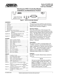
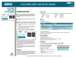
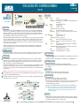
TOTAL ACCESS OPTI-3 CONTROLLER MODULE
1550 NM
OPTI-3
CONTROLLER
OPTI-3
1184002L4
LED STATUS
FIRMWARE RELEASE
This job aid relates to OPTI-3 System Release 1.3 (Dseries). The menus and functionality are an extension of the prior system
release (OPTI-3 System Release 1.2 - Cseries). The latest software is not compatible with System Release 1.1 (Bseries).
APS PUSHBUTTON
INSTALLATION
■
The Total Access OPTI-3 can be installed in either a Rackmount Chassis (RMC), P/N 1184003L1, or a Wallmount Chassis
(WMC), P/N 1184001L1. The RMC provides two OCM slots, side by side, with slot A on the left and slot B on the right. (See
Figure below.) The WMC provides two OCM slots, positioned vertically with slot A below slot B. Ensure the appropriate
chassis is installed before proceeding with the OCM installation.
■
APS
TU
S
TIC
S
DS
3-1
DS
3DS 2
3-3
AC
O
OP
STA
DESCRIPTION
TEST ACO
ENABLE
CRAFT
#61184002L4-22B#
The Total Access® OPTI-3 Controller Module (OCM) provides an OC-3 interface to the network and three ADD/DROP DS3
interfaces to the Loop. The OCM can be configured for a point-to-point configuration or subtended from 3rd party SONET
equipment. The OCM operates in terminal mode only. The compact design mounts in either a rackmount or wallmount
chassis, requiring less space and provides optional redundancy. It can automatically switch to the offline unit in the event of
optical signal failure or degradation. The modules are fully hot-swappable.
Compliant with SONET standards, the OCM functions as a terminal multiplexer. It supports 1+1 OC-3 equipment and facility
protection, 1:1 OC-3 equipment protection (system provisioned for optical Ycable), 1:1 DS3 facility protection, and detects
standard optical related alarm conditions. The OCM can be configured to operate redundantly with optional protection of
the optics components. It can be upgraded online from un-protected to protected and operating software can be upgraded
remotely in Back-to-Back configurations.
The OCM is easily managed with TL1 commands over the Data Communications Channel (DCC) or via Command Line
Interface (CLI) through the local craft interface. Additional features include remote alarm transport via DCC and alarm
reporting to legacy alarm systems.
Carefully insert the OCM halfway into the selected slot. Route the fiber cables through the notch on the OCM front panel and
approximately 4 inches past the SC receptacles (to create slack). Gently but firmly push the OCM all the way into the slot,
being careful not to pinch the fibers between the front panel and the shelf. Push the latch/ejector tab toward the front panel
to lock it into place.
WARNING: Once fully inserted into the chassis, the module will be powered (provided power is connected to the chassis).
2
3
61184002L4-22B
0401
● Green
In-Service
● Yellow
Unit is Out-of-Service – Unassigned
✷ Flashing Yellow Unit is Out-of-Service – Maintenance or is ONLINE and inhibited
from switching
● Red
Unit has an equipment failure
OPTICS
● Green
Normal Operation
● Yellow
Soft failure (e.g. RDI)
✷ Flashing Yellow Unit in Test (e.g. Loopback)
● Red
LOS, LOL, and other hard alarms on optical interface
✷ Flashing Red
Unit in Test (e.g. Loopback) with an alarm present on the Optical
Interface
DS3-1 – DS3-3 ● Green
Unit is ONLINE (DS3 TX ON)
● Yellow
Soft failure (e.g. RDI)
✷ Flashing Yellow Unit in Test (e.g. Loopback)
● Red
LOS, LOL, and other hard alarms on DS3 interface
✷ Flashing Red
Unit in Test (e.g. Loopback) with an alarm present on the DS3
Interface
ACO
● Yellow
When displayed on the OCM at the CO, indicates acknowledged
active alarms at the RT
✷ Flashing Yellow When displayed on the OCM at the CO, indicates an unacknowledged active alarms at the RT
● Red
Acknowledged alarms active on the shelf
✷ Flashing Red
Unacknowledged alarms active on the shelf
1550nm
CLEI: SOI4JN4D_ _
1
JOBAID
When the OCM powers up, it performs a self-test. The front panel LEDs illuminate for approximately 8 seconds. The self-test
is complete once the STATUS LED illuminates green.
If installing a redundant system, repeat the preceding procedure for slot B. If not installing a second OCM, a blank faceplate
(P/N 1184005L1) must cover the empty slot.
STATUS
When depressed simultaneously with the TEST/ENABLE switch on the Offline unit, a switch is forced
between the two OCMs.
When depressed with the TEST/ENABLE switch on the Online unit, it toggles LOCKOUT status.
TEST/ENABLE BUTTON
■
■
When depressed alone, tests all unit LEDs (multicolor LEDs appear YELLOW).
When depressed simultaneously with the APS switch on the Offline unit, a switch is forced between
the two OCMs.
ACO BUTTON
■
■
When depressed after an audible alarm is sounded, silences the alarm.
When depressed after any other alarm is triggered, acknowledges alarm.
CRAFT INTERFACE
■
■
■
■
Provides menu access via RS-232 (Craft) port on the front panel.
Connects to VT100 compatible terminal using a DB-9 serial cable.
Requires setting VT100 terminal emulation (to 9600, 19200, 38400, 57600, or 115200 bps), 8 Data Bits,
No Parity, 1 Stop Bit, and No Flow Control. (The baud rate default is 9600 bps, which can be
modified through the VT100 menu system.
Provides access to both OCMs installed in the chassis with connection to either OCM craft port.
NOTE: The OPTI-3 is an LR (long reach) optical product. When interfacing with IR (intermediate
reach) 3rd party equipment, the optical receive signal may need to be padded to avoid
overloading the optical receive signal. The receive signal level should be within −8 dbm to
−28 dbm for IR equipment.
WARRANTY
C A U T I O N !
SUBJECT TO ELECTROSTATIC DAMAGE
OR DECREASE IN RELIABILITY.
HANDLING PRECAUTIONS REQUIRED.
ADTRAN will replace or repair this product within the warranty period if it does not meet its published
specifications or fails while in service. Warranty information can be found at www.adtran.com/warranty.
U.S. and Canada customer Faxback: 877-457-5007, Document 414.
■ For a complete Installation and Maintenance Practice (P/N 61184002L4-5): 877-457-5007, Faxback Document 964. Please have your fax number ready. ■
TOTAL ACCESS OPTI-3 CONTROLLER MODULE
1550 NM
PROVISIONING OPTIONS
Upon initial installation, the OCM uses factory default settings. To provision the OCM, connect a
terminal emulator via the RS-232 (DB-9) connector on the front panel. The terminal must be VT100
compatible and set for 9600 bps, 8 data bits, no parity and 1 stop bit. The following table lists the
provisioning settings and their default values. The settings are retained in a nonvolatile memory device
in case of power loss to the OCM.
Options
Settings (Default in Bold)
Working Service State
Protect Service State
DS3 Provisioning
DS3#1 Name
DS3#1 Interface
DS3#1 Line Build Out
DS3#2 Name
DS3#2 Interface
DS3#2 Line Build Out
DS3#3 Name
DS3#3 Interface
DS3#3 Line Build Out
Signal Fail (SF) Thresh
Signal Degrade (SD) Thresh
Provisionable Alarms
Clock Source (TX)
In Service, Out Of Service – Maintenance, Out Of Service – Unassigned
In Service, Out Of Service – Maintenance, Out Of Service – Unassigned
OC3 TX SYNC MSG
DCC Provisioning
DCC Service State
DCC IP Address
CLLI Code
NSAP Area Address
LAPD Window Size
LAPD T200 Value
LAPD T203 Value
LAPD N200 Value
LAPD N201 Value
Network Configuration
Baud Rate
Screen Height
Screen Width
Ethernet Interface
IP Address
Subnet Mask
Default Gateway
SNMP Trap Hosts
SNMP System Name
SNMP System Location
SNMP Read Community
User Defined
Enable, Disable
Short, Long
User Defined
Enable, Disable
Short, Long
User Defined
Enable, Disable
Short, Long
1x10⁻³, 1x10⁻⁴, 1x10⁻⁵
1x10⁻⁵, 1x10⁻⁶, 1x10⁻⁷, 1x10⁻⁸, 1x10⁻⁹
See the Provisionable Alarms section to the right of this table.
1. Receive OC-3 from both Fiber A & Fiber B
2. Receive OC-3 from Fiber A
3. Receive OC-3 from Fiber B
4. Free Run
5. External DS1 SF or ESF from both inputs
6. External DS1 SF or ESF from Primary input
7. External DS1 SF or ESF from Secondary input
8. External DS1 ESF w/Sync from both inputs
9. External DS1 ESF w/Sync from Primary input
10. External DS1 ESF w/Sync from Secondary input
Derive From Source, Don’t Use
Network, User (Option is available when Mount Location is Subtended)
User Defined
User Defined – up to 20 alphanumeric characters
User Defined – (Option is available when Mount Location is Subtended)
1..7..127 (Option is available when Mount Location is Subtended)
200..20000 (Option is available when Mount Location is Subtended)
4000..10000..120000 (Option is available when Mount Location is Subtended)
2..3..16 (Option is available when Mount Location is Subtended)
512..1500 (Option is available when Mount Location is Subtended)
9600, 19200, 38400, 57600, 115200
20..24..9999
40..80..9999
Enable, Disable
User Defined – Format = x.x.x.x where x = 0-255
User Defined – Format = x.x.x.x where x = 0-255
User Defined – Format = x.x.x.x where x = 0-255
User Defined – Format = x.x.x.x (x4)
User Defined
User Defined
Public, Private
SNMP Write Community
Time and Date
Mount Location
Account Provisioning
Remote Alarm Reporting
TL-1 Server
TL-1 Port
TL-1 Echo
Menu Server
Menu Port
Restore Factory Defaults
Restore Management Defaults
PRICING AND AVAILABILITY 800.827.0807
TECHNICAL SUPPORT 800.726.8663
RETURN FOR REPAIR 256.963.8722
www.adtran.com
61184002L4-22B
Public, Private
User Defined
Central Office, Remote, Subtended
Account 1-14 (Username, Password, Permission)
Enabled, Disabled (Option is available only in Central Office mode)
Enabled, Disabled
256..2001..2999 (Note: TL-1 Port and Menu Port cannot be the same value)
On, Off
Enabled, Disabled
23..2999 (Note: TL-1 Port and Menu Port cannot be the same value)
LINKED PROVISIONING
The online unit’s provisioning settings are written to the standby unit. Linked Provisioning is always enabled.
DCC MODES
1. Back-to-Back Mode
Back-to-Back mode is used when OCMs are connected together in a point-to-point setup. It consists of one OCM
configured for Central Office and the other for Remote. This mode of operation supports accessing the remote OCM
menus, either by the CO craft port or the CO Ethernet LAN (via Telnet). This remote management is carried over the
DCC section on the fibers between the OCMs. This mode of operation supports remote management of other ADTRAN
equipment subtended from the OCM at the remote site. TFTP and SNMP are supported in this mode, both on a local
Ethernet access and to the remote OCM. NMA access is supported with TL1 via Telnet, where NMA can access both
devices via the CO TL1 session (CO acts as GNE, 1 IP address assigned).
2. Subtended Mode
The OCM functions as a full SONET terminal multiplexer in a new or existing SONET network. It consists of one OCM
configured for Subtended mode. This mode allows each OCM to directly connect to SONET backbone equipment.
Management access is also provided over the DCC to other network elements on the SONET ring. The DCC Interface
must be properly configured, LAPD parameters and NSAP Area Address, for the SONET network for remote OCM
management. The OCM can be also used as a GNE device to allow TL1 access to the existing SONET network.
PROVISIONABLE ALARMS
1. Regular Alarms <Regular Alarm List, 27 available choices>
2. Threshold Alarms <Threshold Alarm List, 22 available choices>
3. Environment Alarms
4. Restore Alarm Defaults
NOTE: Refer to the Installation and Maintenance Practice (P/N 61184002L3-5) for details and options.
SOFTWARE UPGRADE
Software downloads for the local OCM are provided using TFTP, XModem, and YModem protocols in any DCC mode. Software
downloads to the remote OCM through the CO OCM is only supported in a Back-to-Back mode. TFTP downloads are provided through the Ethernet interface (provided through the rear of the chassis) or over the DCC channel (TFTP over DCC channel
only provided when configured for Back-to-Back mode). XModem and YModem downloads are provided through the craft
port and Telnet connections.
Code
COMPLIANCE
Power Code (PC)
Telecommunication Code (TC)
Installation Code (IC)
Input Output
F
–
A
C
–
–
WARNING: The 10/100baseT interface and DS3 interfaces MUST NOT be
metallically connected to interfaces which connect to the Outside Plant
or its wiring. These interfaces are designed for use as intra-building interfaces only. The addition of Primary Protectors is
not sufficient protection in order to connect these interfaces metallically to OSP wiring.
This product intended for use in Restricted Access Areas only, and is intended to be installed in a Type “B” or “E” enclosure.
This product complies with UL 60950.
This device complies with Part 15 of the FCC rules. Operation is subject to the following two conditions: (1) This device may
not cause harmful interference, and (2) this device must accept any interference received, including interference that may
cause undesired operation. Changes or modifications not expressly approved by ADTRAN could void the user’s authority to
operate this equipment.