1
Acer
Aspire M5910(G)
Service Guide
PRINTED IN TAIWAN
Revision History
Please refer to the table below for the updates made on this service guide.
Date
ii
Chapter
Updates
Copyright
Copyright © 2010 by Acer Incorporated. All rights reserved. No part of this publication may be reproduced,
transmitted, transcribed, stored in a retrieval system, or translated into any language or computer language, in
any form or by any means, electronic, mechanical, magnetic, optical, chemical, manual or otherwise, without
the prior written permission of Acer Incorporated.
iii
Disclaimer
The information in this guide is subject to change without notice.
Acer Incorporated makes no representations or warranties, either expressed or implied, with respect to the
contents hereof and specifically disclaims any warranties of merchantability or fitness for any particular
purpose. Any Acer Incorporated software described in this manual is sold or licensed "as is". Should the
programs prove defective following their purchase, the buyer (and not Acer Incorporated, its distributor, or its
dealer) assumes the entire cost of all necessary servicing, repair, and any incidental or consequential
damages resulting from any defect in the software.
Acer is a registered trademark of Acer Corporation.
Intel is a registered trademark of Intel Corporation.
Pentium Dual-Core, Celeron Dual-Core, Core 2 Duo, Core 2 Quad, Celeron, and combinations thereof, are
trademarks of Intel Corporation.
Other brand and product names are trademarks and/or registered trademarks of their respective holders.
iv
Conventions
The following conventions are used in this manual:
SCREEN
MESSAGES
Denotes actual messages that appear on screen.
NOTE
Gives additional information related to the current topic.
WARNING
Alerts you to any physical risk or system damage that might result from doing
or not doing specific actions.
CAUTION
Gives precautionary measures to avoid possible hardware or software
problems.
IMPORTANT
Reminds you to do specific actions relevant to the accomplishment of
procedures.
v
Service Guide Coverage
This Service Guide provides you with all technical information relating to the BASIC CONFIGURATION
decided for Acer's "global" product offering. To better fit local market requirements and enhance product
competitiveness, your regional office MAY have decided to extend the functionality of a machine (e.g. add-on
card, modem, or extra memory capability). These LOCALIZED FEATURES will NOT be covered in this generic
service guide. In such cases, please contact your regional offices or the responsible personnel/channel to
provide you with further technical details.
FRU Information
Please note WHEN ORDERING FRU PARTS, that you should check the most up-to-date information available
on your regional web or channel. If, for whatever reason, a part number change is made, it will not be noted in
the printed Service Guide. For ACER-AUTHORIZED SERVICE PROVIDERS, your Acer office may have a
DIFFERENT part number code to those given in the FRU list of this printed Service Guide. You MUST use the
list provided by your regional Acer office to order FRU parts for repair and service of customer machines.
vi
Table of Contents
System Tour
Features
Block Diagram
System Components
Front Panel
Rear Panel
Hardware Specifications and Configurations
Power Management Function(ACPI support function)
System Utilities
CMOS Setup Utility
Entering CMOS setup
Navigating Through the Setup Utility
Setup Utility Menus
System Disassembly
Disassembly Requirements
Pre-disassembly Procedure
Removing the Side Panel
Removing the Heat Sink Fan Assembly
Removing the Processor
Removing the VGA Card
Removing the TV Card
Removing the Mode Card
Removing the Hard Disk Drive
Removing the Front Bezel
Removing the Rear USB Board
Removing the Cables
Removing the System Fan
Removing the Optical Drive
Removing the Power Supply
Removing the Memory Modules
Removing the Removable HDD bay
Removing the Mainboard
System Troubleshooting
Hardware Diagnostic Procedure
System Check Procedures
Power System Check
System External Inspection
System Internal Inspection
Beep Codes
Checkpoints
BIOS Recovery
Jumper and Connector Information
M/B Placement
Jumper Setting
Setting Jumper
1
1
4
5
5
6
7
10
11
11
12
12
13
26
26
27
28
29
30
31
32
33
35
36
37
38
39
40
41
42
43
45
46
46
47
47
47
47
48
49
52
53
53
55
55
vii
FRU (Field Replaceable Unit) List
Aspire M5910(G) Exploded Diagram(AM551 ASSY)
Aspire M5910(G) Exploded Diagram(AM550 ASSY)
Aspire M5910(G) FRU List
viii
61
62
63
64
Chapter 1
System Tour
Features
Below is a brief summary of the computer’s many feature:
NOTE: The features listed in this section is for your reference only. The exact configuration of the system
depends on the model purchased.
Operating System
•
Microsofte Windows 7 Home Premium 64-bit
•
Microsofte Windows 7 Home Basic 64-bit
•
Microsofte Windows 7 Home Premium 32-bit
•
Microsofte Windows 7 Home Basic 32-bit
•
Linpus X-window mode
•
FreeDos
Processor
•
Socket Type: Intel Socket T LGA 1156 pin
•
Socket Quantity: 1
•
Processor Type:
•
•
Intel Lynnfield / Clarkdale
FMB
•
95W + 65W FMB
Chipset
•
PCH: Intel H57
•
Design Criteria:
•
•
Must meet Intel Lynnfield and Clarkdale platform design guides
Super I/O: ITE8720
•
Should support Intel ASFC
•
Should support Intel PECI
PCB
•
uATX / 244*244mm / 4 Layers
Memory subsystem
•
Socket Type: DDR III connector
•
Socket Quantity: 4
•
Channel A: slot 0, 1; Channel B: slot 2, 3
•
Different colors for slot 0/2 and slot 1/3
•
Dual channel support
•
Capacity support:
•
Chapter 1
Support DDR3 1.5V 1066/1333 (1GB / 2GB / 4GB)
1
•
•
1GB to 16GB Max memory support
Design Criteria:
•
Must meet Intel Lynnfield and Clarkdale Chipset platform design guide
Hard disk
•
Support up to two SATA ports
•
3.5", 25.4mm
•
Capacity and models are listed on AVLC
Optical disk
•
Support two SATA 5.25" standard ODD
•
Support DVD-ROM, DVD-SuperMulti, BD-combo, BD-rewrite
•
Maximum ODD depth to 185mm with bezel
•
Models are listed on AVLC
Graphics card
•
No mechanical retriction to support for double slot, full length graphics cards in the single PSIe X16 slot
On-Board Graphic solution
•
Intel HD Graphics (Clarkdale series CPU)
•
DVMT 5.0 technology support
•
Enhanced 3D and Clear Video technology support
•
1 D-sub VGA port on rear
•
Dual View function support
Serial ATA controller
•
Slot Type: SATA connector
•
Six SATA ports:
•
•
4 for HDD
•
2 for ODD
Storage Type support:
1.HDD : Support RAID 0/1/5/10
2.CD-ROM/CD-RW/DVD-ROM/DVD-RW/DVD+RW/DVD Dual/DVD SuperMultiPlus/Blu-Ray ODD
3.AHCI mode supported for internal SATA port
Audio
•
Chip : Realtek ALC662VC-0
•
Connectors support:
•
Rear 3 jack follow HD audio definition
•
1 front panel audio header (2*5)
LAN
2
•
MAC Controller: H57
•
PHY: REALTEK RTL8111E Giga LAN(ASF suport)
Chapter 1
USB ports
•
•
Ports Quantity: 12
•
6 back panel ports
•
On-board: 2 2*5 headers
•
4 ports for front daughter board
•
Connector Pin: standard Intel FPIO pin definition
Data transfer rate support: USB 2.0/1.1
Extension slot
•
Support one PCIe x 16 slot
•
Support two PCIe x 1 slots
•
Support one PCI slot
Total I/O ports
•
1 PS/2 Keyboard port,
•
1 PS/2 Mouse port
•
1 D-Sub VGA port
•
1 RJ45 LAN port
•
6 USB ports
•
3 ports Audio jack
•
One HD headphone output in front bezel
•
One MIC-IN in front bezel
•
4 * USB H5X2 Header (support 8 ports)
•
1 * Front Audio Pannel H5X2 header
•
1 * Front Panel IO H7X2 Header for Acer pin define
•
1 * H1X4 CPU with SAMRT FAN controller
•
1 * H1X3 System with SAMRT FAN controller
•
1 * H1X4 SPDIFOUT Header for Acer pin define
•
1 * H3X1 Clear CMOS Header (with jumper)
•
1 * onboard Buzzer
•
2 * H1X2 GPIO header
System BIOS
•
16MBits / 2M Bytes
•
AMI Kernel with Acer skin
Power supply
•
Chapter 1
FR500W
3
Block Diagram
4
Chapter 1
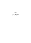
System Components
This section is a virtual tour of the system’s interior and exterior components.
Front Panel
9
1
8
7
2
6
3
4
5
Chapter 1
No.
Component
1
USB 2.0 ports
2
Acer logo
3
Optical drive button
4
Optical drive button (Removable HDD bay for AM551 bezel)
5
Removable HDD bay
6
Power button
7
16 in 1 Card Reader
8
Headphone/Speaker-out/line-out jack
9
Microphone-in jack
5
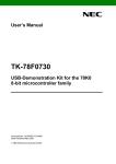
Rear Panel
1
13
2
12
11
3
10
4
9
5
8
6
7
No.
6
Component
1
Power connector
2
PS2 keyboard port
3
VGA port
4
USB 2.0 ports
5
Mic-in
6
Line-out
7
Expansion slot (graphics card and TV tuner card and Mode card)
8
Line-in
9
USB 2.0 ports
10
LAN connector
11
System FAN
12
PS2 mouse port
13
Fan aperture
Chapter 1
Hardware Specifications and Configurations
Processor
Item
Specification
Processor Type
CPUs which complaint with Intel FSB 800/1066/1333 MHz CPUs
Socket Type
Intel Socket T LGA 1156 pin
Minimum operating speed
0 MHz (If Stop CPU Clock in Sleep State in BIOS Setup is set to Enabled.)
BIOS
Item
Specification
BIOS code programer
AMI Kernel with Acer skin
BIOS version
P01-A0
BIOS ROM type
SPI ROM
BIOS ROM size
2Mb
Support protocol
SMBIOS(DMI)2.4/DMI2.0
Device Boot Support
Support BBS spec
1st priority: HDD
2nd priority: CD-ROM
3th priority: Removable Device
4th priority: LAN
Support to LS-120 drive
YES
Support to BIOS boot block feature YES
IOS Hotkey List
Hotkey
Function
Description
Del
Enter BIOS Setup Utility
Press while the system is booting to enter BIOS Setup Utility.
Main Board Major Chips
Item
Specification
Chipset
PCH: Intel H57
Audio controller
Realtek ALC662VC-0
LAN controller
REALTEK RTL8111E Giga LAN(ASF suport)
HDD controller
PCH: Intel H57
Chapter 1
7
Memory Combinations
Slot
Memory
Total Memory
Slot 1
1GB,2GB,4G
1G ~4GB
Slot 2
1GB,2GB,4G
1G ~4GB
Slot 3
1GB,2GB,4G
1G ~4GB
Slot 4
1GB,2GB,4G
1G ~4GB
Maximum System Memory Supported
1G~16GB
System Memory
Item
Specification
Memory slot number
4 slot
Support Memory size per socket
1GB/2GB/4GB
Support memory type
DDRIII
Support memory interface
DDRIII 1066/1333
Support memory voltage
1.5V
Support memory module package
240-pin DDRIII
Support to parity check feature
Yes
Support to error correction code (ECC) feature No
Memory module combinations
You can install memory modules in any combination as long as
they match the above specifications.
Audio Interface
Item
Specification
Audio controller
PCH: Intel H57
Audio controller type
Realtek ALC662VC-0
Audio channel
codec 5.1
Audio function control
No
Mono or stereo
Stereo
Compatibility
The ALC662VC series support host audio controller from the Intel ICH series
chipset, and also from any other HDA compatible audio controller. With EAX/
Direct Sound 3D/I3DL2/A3D compatibility, and excellent software utilities like
environment sound emulation, multiple bands of software equalizer and
dynamic range control, optional Dolby, Digital Live, DTS CONNECT, and Dolby
Home Theater programs, provides an excellent home entertainment package
and game experience for PC users.
Music synthesizer
No
Sampling rate
192KHz (max)
MPU-401 UART support
No
Microphone/Headphone jack
Supported
8
Chapter 1
SATA Interface
Item
Specification
SATA controller
PCH: Intel H57
SATA controller resident bus
PCI bus
Number of SATA channel
SATA X 6
Support bootable CD-ROM
YES
USB Port
Item
Specification
Universal HCI
USB 2.0/1.1
USB Class
Support legacy keyboard for legacy mode
USB Connectors Quantity
6 back real ports
4 top bezel ports
2 H5X2 Hedaer
Environmental Requirements
Item
Specification
Temperature
Operating
+5°C ~ +35°C
Non-operating
-20 ~ +60°C (Storage package)
Humidity
Operating
15% to 80% RH
Non-operating
10% to 90% RH
Vibration
Operating (unpacked)
5 ~ 500 Hz: 2.20g RMS random, 10 minutes per axis in all 3 axes.
5 ~500 Hz: 1.09g RMS random, 1 hour per axis in all 3 axes.
Power Management
Devices
S1
S3
S4
S5
Power Button
V
V
V
V
USB Keyboard/Mouse
V
V
N/A
N/A
PME
Disabled
Disabled
Disabled
Disabled
RCT
Disabled
Disabled
Disabled
Disabled
WOR
Disabled
Disabled
Disabled
Disabled
•
Devices wake up from S3 should be less than.
•
Devices wake up from S5 should be less than 10 seconds.
Chapter 1
9
Power Management Function(ACPI support function)
Device Standby Mode
•
Independent power management timer for hard disk drive devices(0-15 minutes,time step=1minute).
•
Hard Disk drive goes into Standby mode(for ATA standard interface).
•
Disable V-sync to control the VESA DPMS monitor.
•
Resume method:device activated (keyboard for DOS, keyboard &mouse for Windows.
•
Resume recovery time 3-5sec
Global Standby Mode
•
Global power management timer(2-120minutes,time step=10minute).
•
Hard disk drive goes into Standby mode(for ATA standard interface).
•
Disable H-sync and V-sync signals to control the VESA DPMS monitor.
•
•
Resume method: Resume to original state by pushing external switch Button,modem ring in,keyboard
an mouse for APM mode.
Resume recovery time :7-10sec
Suspend Mode
•
•
Independent power management timer(2-120minutes,time step=10minute)or pushing extern switch
button.
CPU goes into SMM
•
CPU asserts STPCLK# and goes into the Stop Grant State.
•
LED on panel turns amber colour.
•
Hard disk drive goes into SLEEP mode (for ATA standard interface).
•
Disable H-sync and V-sync signals to control the VESA DPMS monitor.
•
Ultra I/O and VGA chip go into power saving mode.
•
Resume method: Resume to original state by pushing external switch Button,modem ring in,keyboard
an mouse for APM mode
•
Return to original state by pushing external switch button,modem ring in and USB keyboard for ACPI
mode.
ACPI
10
•
ACPI specification 1.0b
•
S0,S1,S2 and S5 sleep state support.
•
On board device power management support.
•
On board device configuration support.
Chapter 1
Chapter 2
System Utilities
CMOS Setup Utility
CMOS setup is a hardware configuration program built into the system ROM, called the complementary metaloxide semiconductor (CMOS) Setup Utility. Since most systems are already properly configured and
optimized, there is no need to run this utility. You will need to run this utility under the following conditions.
•
When changing the system configuration settings
•
When redefining the communication ports to prevent any conflicts
•
When modifying the power management configuration
•
When changing the password or making other changes to the security setup
When a configuration error is detected by the system and you are prompted ("Run Setup"
message) to make changes to the CMOS setup
NOTE: If you repeatedly receive Run Setup messages, the battery may be bad. In this case, the system
cannot retain configuration values in CMOS. Ask a qualified technician for assistance.
•
CMOS setup loads the configuration values in a battery-backed nonvolatile memory called CMOS RAM. This
memory area is not part of the system RAM which allows configuration data to be retained when power is
turned off.
Before you run the CMOS Setup Utility, make sure that you have saved all open files. The system reboots
immediately after you close the Setup.
NOTE: CMOS Setup Utility will be simply referred to as “BIOS”, "Setup", or "Setup utility" in this guide.
The screenshots used in this guide display default system values. These values may not be the same
those found in your system.
Chapter 2
11
Entering CMOS setup
1.
Turn on the server and the monitor.
If the server is already turned on, close all open applications, then restart the server.
2.
During POST, press Delete.
If you fail to press Delete before POST is completed, you will need to restart the server.
The Setup Main menu will be displayed showing the Setup’s menu bar. Use the left and right arrow keys
to move between selections on the menu bar.
Navigating Through the Setup Utility
Use the following keys to move around the Setup utility.
•
Left and Right arrow keys – Move between selections on the menu bar.
•
Up and Down arrow keys – Move the cursor to the field you want.
•
PgUp and PgDn keys – Move the cursor to the previous and next page of a multiple page menu.
•
Home – Move the cursor to the first page of a multiple page menu.
•
End – Move the cursor to the last page of a multiple page menu.
+ and - keys – Select a value for the currently selected field (only if it is user-configurable). Press
these keys repeatedly to display each possible entry, or the Enter key to choose from a pop-up
menu.
NOTE: Grayed-out fields are not user-configurable.
•
•
Enter key – Display a submenu screen.
NOTE: Availability of submenu screen is indicated by a (>).
•
12
Esc – If you press this key:
•
On one of the primary menu screens, the Exit menu displays.
•
On a submenu screen, the previous screen displays.
•
When you are making selections from a pop-up menu, closes the pop-up without making a
selection.
•
F1 – Display the General Help panel.
•
F6 – Press to load optimized default system values.
•
F7 – Press to load fail-safe default system values.
•
F10 – Save changes made the Setup and close the utility.
Chapter 2
Setup Utility Menus
The Setup Main menu includes the following main setup categories.
Parameter
Description
Product Information
This page shows the relevant information of the main board
Standard CMOS Features
This setup page includes all the items in standard compatible BIOS
Advanced BIOS Features
This setup page includes all the items of Award special enhanced features
Advanced Chipset Features
This setup page includes all advanced chipset features
Integrated Peripherals
This setup page includes all onboard peripherals
Power Management Setup
This setup page includes all the items of Green function features
PC Health Status
This setup page is the System auto detect Temperature, voltage, and fan speed
Frequency/Voltage Control
This setup page is the System Frequency setup
BIOS Security Features
Change, set or disable password. It allows you to limit access to the System
Load Default Setting
Load Default Setting indicates the value of the system parameters which the system would be
in best performance configuration
Save & Exit Setup
Save CMOS value settings to CMOS and exit setup
Exit Without Saving
Abandon all CMOS value changes and exit setup
In the descriptive table following each of the menu screenshots, settings in boldface are the default and
suggested settings.
Chapter 2
13
Product Information
The Product Information menu displays basic information about the system. These entries are for your
reference only and are not user-configurable.
Parameter
Description
Processor Type
Type of CPU installed on the system.
Processor Speed
Speed of the CPU installed on the system.
System Memory
Total size of system memory installed on the system.
Product Name
Product name of the system.
System Serial Number
Serial number of the system.
System BIOS Version
Version number of the BIOS setup utility.
BIOS Release Date
Date when the BIOS setup utility was released
Asset Tag Number
Asset tag number of this system.
14
Chapter 2
Standard CMOS Features
Parameter
Description
System Date
Set the date following the weekday-month-day-year format.
System Time
Set the system time following the hour-minute-second format.
Halt On
Determines whether the system will stop for an error during the POST.
Option
All, But Keyboard
No Errors
All Errors
Chapter 2
15
Advanced BIOS Feature
Parameter
Description
Option
Quick Boot
Allows you to decrease the time it takes to boot the computer by shortening
or skipping certain standard booting process.
Enabled
Quiet Boot
When enabled, the BIOS splash screen displays during startup.
Enabled
When disabled, the diagnostic screen displays during startup.
Disabled
Specifies the boot order from the available devices.
Hard Disk
1st/2nd/3rd/4th Boot Device
Disabled
CD^DVD
Removable
Device
LAN
Hard Disk Drive Priority
Press Enter to access the Hard Disk Drive Priority submenu and specify the boot device
priority sequence from available hard drives.
Optical Disk Drives Priority
Press Enter to access the Optical Disk Drive Priority submenu and specify the boot device
priority sequence from available CD/DVD drives.
Removable Device Priority
Press Enter to access the Removable Device Priority submenu and specify the boot device
priority sequence from available removable drives.
Bootup Num-Lock
Selects power on state for Num Lock.
USB Beep Message
Enables or disables BIOS to display error beeps or messages during USB
device enumeration.
On
Off
16
Disabled
Enabled
Chapter 2
Advanced Chipset Features
Parameter
Description
Option
Intel EIST
When enabled, this feature allows the OS to reduce power consumption.
Enabled
When disabled, the system operates at maximum CPU speed.
Disabled
When enabled, the processor disables code execution when a worm
attempts to insert a code in the buffer preventing damage and worm
propagation.
Enabled
Intel XD Bit
Disabled
When disabled, the processor forces the Execute Disable (XD) Bit feature
flag to always return to 0.
Intel VT
Enables or disables the Virtualization Technology (VT) availability. If
enabled, a virtual machine manager (VMM) can utilize the additional
hardware virtualization capabilities provided by this technology.
Enabled
Disabled
Note: A full reset is required to change the setting.
Memory Hole Remapping
Enables or disables remapping of overlapped PCI memory above the total
physical memory.
Enabled
Video Memory Size
Select a Video memory size
32MB
DVMT Memory Size
Select a DVMT memory size
256MB
Chapter 2
Disabled
17
Integrated Peripherals
Parameter
Description
Onboard SATA Controller
Enables or disables the onboard SATA controller.
Option
Enabled
Disabled
Onboard SATA Mode
Select an operating mode for the onboard SATA.
RAID
Native IDE
Onboard USB Controller
Enables or disables the onboard USB controller.
Legacy USB Support
Enables or disables support for legacy USB devices.
Enabled
Disabled
Enabled
Disabled
USB Storage Emulation
Enables or disables support for legacy USB devices.
Onboard Audio Controller
Enables or disables the onboard audio controller.
Enabled
Disabled
Enabled
Disabled
Onboard LAN Controller
Enables or disables the onboard LAN controller.
Onboard LAN Option ROM
Enables or disables the load of embedded option ROM for onboard
network controller.
Enabled
Disabled
18
Enabled
Disabled
Chapter 2
Power Management Setup
Parameter
Description
Option
ACPI Suspend Mode
Select an ACPI state.
S3 (STR)
Deep power off mode
Select the Deep power off Mode
S1 (POS)
Enabled
Disabled
Power On by RTC Alarm
Enables or Disables to wake up the system by RTC Alarm Function
Enabled
Power On by PCIE Devices
Enables or disables to wake up the system from a power saving mode
through an event on PCI Express device.
Enabled
Power On by PCI Devices
Enables or disables to wake up the system from a power saving mode
through an event on PCI device.
Enabled
Wake Up by PS/2 KB/
Mouse
Enables or disables to wake up the system from a power saving mode
using a PS2 keyboard or mouse.
Enabled
Wake Up by USB KB/
Mouse
If enabled, press any key or click the mouse will wake system from S1/
S3 state.
Enabled
Restore On AC Power Loss
Enables or disables the system to reboot after a power failure or
interrupt occurs.
Power Off
Disabled
Disabled
Disabled
Disabled
Disabled
Power On
Last State
Chapter 2
19
PC Health Status
Parameter
Description
Option
Smart FAN
Enables or disables the smart system fan control function.
Enabled
Disabled
20
Chapter 2
Frequency/Voltage Control
Parameter
Description
Option
Clock to All DIMM/PCI
Enables or disables control the clock to all DIMM/PCI
Enabled
Disabled
Spread Spectrum
Chapter 2
Enables or disables the reduction of the mainboard’s EMI.
Enabled
Note: Remember to disable the Spread Spectrum feature if you are
overclocking. A slight jitter can introduce a temporary boost in clock
speed causing the overclocked processor to lock up.
Disabled
21
BIOS Security Features
Parameter
Description
Supervisor Password
Indicates the status of the supervisor password.
User Password
Indicates the status of the user password.
Change Supervisor
Password
Supervisor password prevents unauthorized access to the BIOS Setup Utility.
Press Enter to change the Supervisor password.
Setting a supervisor password
1.
Use the up/down arrow keys to select Change Supervisor Password menu then press Enter.
A password box will appear.
2.
Type a password then press Enter.
The password may consist up to six alphanumeric characters (A-Z, a-z, 0-9)
3.
Retype the password to verify the first entry then press Enter again.
4.
Press F10.
5.
Select Yes to save the new password and close the Setup Utility.
Changing the supervisor password
1.
Use the up/down arrow keys to select Change Supervisor Password menu then press Enter.
2.
Type the original password then press Enter.
3.
Type a new password then press Enter.
4.
Retype the password to verify the first entry then press Enter again.
5.
Press F10.
6.
Select Yes to save the new password and close the Setup Utility.
Removing a supervisor password
22
1.
Use the up/down arrow keys to select Change Supervisor Password menu then press Enter.
2.
Enter the current password then press Enter.
3.
Press Enter twice without entering anything in the password fields.
Chapter 2
Load Default Settings
The Load Default Settings menu allows you to load the default settings for all BIOS setup parameters. Setup
defaults are quite demanding in terms of resources consumption. If you are using low-speed memory chips or
other kinds of low-performance components and you choose to load these settings, the system might not
function properly.
Chapter 2
23
Save & Exit Setup
The Save & Exit Setup menu allows you to save changes made and close the Setup Utility.
24
Chapter 2
Exit Without Saving
The Exit Without Saving menu allows you to discard changes made and close the Setup Utility.
Chapter 2
25
Chapter 3
System Disassembly
This chapter contains step-by-step procedures on how to disassemble the desktop computer for maintenance
and troubleshooting.
Disassembly Requirements
To disassemble the computer, you need the following tools:
•
Wrist grounding strap and conductive mat for preventing electrostatic discharge
•
Flat-blade screwdriver
•
Philips screwdriver
•
Hex screwdriver
•
Plastic flat-blade screwdriver
Plastic tweezers
NOTE: The screws for the different components vary in size. During the disassembly process, group the
screws with the corresponding components to avoid mismatch when putting back the components.
•
Chapter 3
26
Pre-disassembly Procedure
Before proceeding with the disassembly procedure, perform the steps listed below:
27
1.
Turn off the system and all the peripherals connected to it.
2.
Unplug the power cord from the power outlets.
3.
Unplug the power cord from the system.
4.
Unplug all peripheral cables from the system.
5.
Place the system unit on a flat, stable surface.
Chapter 3
Removing the Side Panel
1.
Remove the two screws located on the rear edge of the side panel.
2.
Slide the side panel toward the back of the chassis until the tabs on the cover disengage with the slots on
the chassis.
3.
Lift the side panel away from the server and put it aside for reinstallation later.
Chapter 3
28
Removing the Heat Sink Fan Assembly
WARNING:The heat sink becomes very hot when the system is on. NEVER touch the heat sink with any metal
or with your hands.
29
1.
disconnect the fan cable from the mainboard.
2.
Use a long-nosed screwdriver to loosen the four screws on the heat sink, in the order as shown below.
3.
Lift the heat sink fan assembly away from the mainboard.
Chapter 3
Removing the Processor
IMPORTANT:Before removing a processor from the mainboard, make sure to create a backup file of all
important data.
WARNING:The processor becomes very hot when the system is on. Allow it to cool off first before handling.
1.
Release the load lever.
2.
Lift the load lever and load plate to the fully open, upright position (1) and (2).
3.
Pull out the processor from the socket.
IMPORTANT: If you are going to install a new processor, note the arrow on the corner to make sure the
processor is properly oriented over the socket.
Chapter 3
30
Removing the VGA Card
31
1.
Release the Slot cover lock.
2.
Remove the screw from chassis.
3.
Disconnect the power cables from the VGA card.
4.
One finger Press the clip and the same time Gently pull the card to remove it from the mainboard.
Chapter 3
Removing the TV Card
1.
Gently pull the TV card to remove it from the mainboard.
Chapter 3
32
Removing the Mode Card
1.
33
Gently pull the Mode card to remove it from the mainboard.
Chapter 3
Removing the Hard Disk Drive
1.
Disconnect the data and power cables from the rear of the optical drive and the mainboard.
2.
Remove the HDD bracket
a.
Remove the screw that secures the HDD bracket to the ODD bracket.
b.
Lift the bracket up and turn it over.
Chapter 3
34
3.
35
Remove the HDD module
a.
Remove the eight screws secure the HDD module to the HDD bracket.
b.
Slide the HDD out of the bracket.
Chapter 3
Removing the Front Bezel
1.
Disconnect the LED cable.
2.
Release the front bezel from the chassis interior.
3.
Pull the bezel away from the chassis.
Chapter 3
36
Removing Rear USB Board
37
1.
Remove USB cable
2.
Release the screw of rear usb.
3.
Remove the rear usb board.
Chapter 3
Removing the Cables
1.
Remove power switch and LED cables from slot of M/B
2.
Remove HDD Data and ODD Data cables from slot of M/B.
Powe- Led Cabl e
HDD Cabl e
3.
Remove USB1/2/3 cable from M/B.
4.
Remove FIO cable and Audio cable from M/B
Chapter 3
ODD Cabl e
38
Remove System FAN
39
1.
Remove System FAN cable from M/B.
2.
Release four screws according to the following picture.
3.
Take off the system fan from chassis.
Chapter 3
Removing the Optical Drive
1.
Disconnect the data and power cables from the rear of the optical drive.
Power cabl e
2.
Remove Four screw from the optical drive.
3.
Pull the drive out of the drive.
Chapter 3
Dat a cabl e
40
Removing the Power Supply
41
1.
Disconnect the 24-pin and 4-pin power supply cables from the mainboard.
2.
Remove the four screw that secures the power supply to the chassis.
3.
Lift the power supply module out of the chassis.
Chapter 3
Removing the Memory Modules
IMPORTANT:Before removing any DIMM from the memory board, make sure to create a backup file of all
important data.
1.
Press the holding clips on both sides of the DIMM slot outward to release the DIMM.
2.
Gently pull the DIMM upward to pull it away from the M/B.
Chapter 3
42
Removing the removable HDD bay
43
1.
Remove the HDD rail
2.
Remove the screws that secure the HDD bay.
3.
Remove the HDD bay.
Chapter 3
Removing the Mainboard
1.
Remove the eight screws that secure the mainboard to the chassis.
Note:Circuit boards >10 cm² has been highlighted with the yellow rectangle as above image shows.
Please detach the Circuit boards and follow local regulations for disposal.
Chapter 3
44
45
2.
Lift the board from the chassis.
3.
Remove the RTC battery.
Chapter 3
Chapter 4
System Troubleshooting
This chapter provides instructions on how to troubleshoot system hardware problems.
Hardware Diagnostic Procedure
IMPORTANT:The diagnostic tests described in this chapter are only intended to test Acer products. NonAcerproducts, prototype cards, or modified options can give false errors and invalid
systemresponses.
1.
Obtain the failing symptoms in as much detail as possible.
2.
Verify the symptoms by attempting to recreate the failure by running the diagnostic tests or repeating
thesame operation.
3.
Refer to “Power System check” and “Beep Codes” to determine which corrective action to perform.
Chapter 4
46
System Check Procedures
Power System Check
If the system will power on, skip this section. Refer to System External Inspection.
If the system will not power on, do the following:
•
Check if the power cable is properly connected to the system and AC source.
•
Check if the voltage selector switchis set to the correct voltage setting.
System External Inspection
1.
Inspect the LED indicators on the front panel, which can indicate the malfunction.
2.
Make sure that air flow is not blocked.
3.
Make sure nothing in the system is making contact that could short out power.
4.
If the problem is not evident, continue with System Internal Inspection.
System Internal Inspection
1.
Turn off the system and all the peripherals connected to it.
2.
Unplug the power cord from the power outlets.
3.
Unplug the power cord from the system.
4.
Unplug all peripheral cables from the system.
5.
Place the system unit on a flat, stable surface.
6.
Remove the system covers.For instructions on removing system covers, refer to “System Disassembly”.
7.
Verify that components are properly seated.
8.
Verify that all cable connectors inside the system are firmly and correctly attached to their appropriate
connectors.
9.
Verify that all components are Acer-qualified and supported.
10. Replace the system covers.
11. Power on the system.
12. If the problem with the system is not evident, you can try viewing the POST messages and BIOS event
logs during the system startup.
47
Chapter 4
Beep Codes
Beep codes are used by the BIOS to indicate a serious or fatal error to the end user. Beep codes are used
when an error occurs before the system video has been initialized. Beep codes will be generated by the
system board speaker, commonly referred to as the PC speaker.
AMIBIOS displays the checkpoints in the bottom right corner of the screen during POST. This display method
is limited, since it only displays checkpoints that occur after the video card has been activated.
Not all computers using AMIBIOS enable this feature. In most cases, a checkpoint card is the best tool for
viewing AMIBIOS checkpoints.
Beep Symptom
Cause and Description
One short beep
System is ready.
System is OK.
Continuous one long beep
Memory not installed or memory error.
One long beep and two short beeps then
repeat.
VGA not installed or VGA error.
Graphics card error/not installed, graphics card memory
error or graphics card BIOS checksum error.
One long beep then two short beep
BIOS damaged.
BIOS is damaged, BIOS POST jumps to Boot Block to
execute the default procedures.
Two short beeps
CMOS damaged.
CMOS checksum error or CMOS battery loss occurs.
Chapter 4
48
Checkpoints
A checkpoint is either a byte or word value output to I/O port 80h.The BIOS outputs checkpoints throughout
bootblock and Power-On Self Test (POST) to indicate the task the system is currently executing. Checkpoint
sare very useful in aiding software developers or technicians in debugging problems that occur during the preboot process.
Viewing BIOS checkpoints
Viewing all checkpoints generated by the BIOS requires acheckpoint card, also referred to as a POST card or
POST diagnostic card. These are ISA or PCI add-in cards that show the value of I/O port 80h on a LED
display. Checkpoints may appear on the bottom right corner of the screen during POST. This display method
islimited, since it only displays checkpoints thatoccur after the video card has been activated.
Bootblock Initialization Code Checkpoints
The Bootblock initialization code sets up the chipset,memory, and other components before system memory is
available. The following table describes the type of checkpoints that may occur during the bootblock
initialization portion of the BIOS.
NOTE: Please note that checkpoints may differ between different platforms based on system
configuration.Checkpoints may change due to vendor requirements,system chipset or option ROMs
from add-in PCI devices.
Checkpoint
Description
Before D0
If boot block debugger is enabled, CPU cache-as-RAM functionality is enabled at this point.
Stack will be enabled from this point.
D0
Early Boot Strap Processor (BSP) initialization like microcode update, frequency and other
CPU critical initialization. Early chipset initialization is done.
D1
Early super I/O initialization is done including RTC and keyboard controller. Serial port is
enabled at this point if needed for debugging. NMI is disabled. Perform keyboard controller
BAT test. Save power-on CPUID value in scratch CMOS. Go to flat mode with 4GB limit and
GA20 enabled.
D2
Verify the boot block checksum. System will hang here if checksum is bad.
D3
Disable CACHE before memory detection. Execute full memory sizing module. If memory
sizing module not executed, start memory refresh and do memory sizing in Boot block code.
Do additional chipset initialization. Re-enable CACHE. Verify that flat mode is enabled.
D4
Test base 512KB memory. Adjust policies and cache first 8MB. Set stack.
D5
Bootblock code is copied from ROM to lower system memory and control is given to it. BIOS
now executes out of RAM. Copies compressed boot block code to memory in right
segments. Copies BIOS from ROM to RAM for faster access. Performs main BIOS
checksum and updates recovery status accordingly.
D6
Both key sequence and OEM specific method is checked to determine if BIOSrecovery is
forced. Main BIOS checksum is tested. If BIOS recovery is necessary,control flows to
checkpoint E0. See Bootblock Recovery Code Checkpoints sectionfor more information.
D7
Restore CPUID value back into register. The Bootblock-Runtime interface module is moved
to system memory and control is given to it. Determine whether to execute serial flash.
D8
The Runtime module is uncompressed into memory. CPUID information is stored in memory.
D9
Store the Uncompressed pointer for future use in PMM. Copying Main BIOS into memory.
Leaves all RAM below 1MB Read-Write including E000 and F000 shadow areas but closing
SMRAM.
49
Chapter 4
Checkpoint
Description
DA
Restore CPUID value back into register. Give control to BIOS POST (ExecutePOSTKernel).
See POST Code Checkpoints section of document for more information.
DC
System is waking from ACPI S3 state.
E1-E8 ECEE
OEM memory detection/configuration error. This range is reserved for chipset vendors &
system manufacturers. The error associated with this value may be different from one
platform to the next.
Chapter 4
50
Bootblock Recovery Code Checkpoints
The Bootblock recovery code gets control when the BIOS determines that a BIOS recovery needs to occur
because the user has forced the update or the BIOS checksum is corrupt. The following table describes the
type of checkpoints that may occur during the Bootblock recovery portion of the BIOS.
NOTE: Checkpoints may differ between different platforms based on system configuration. Checkpoints
maychange due to vendor requirements, system chipset or option ROMs from add-in PCI devices.
Checkpoint
Description
E0
Initialize the floppy controller in the super I/O. Some interrupt vectors are initialized. DMA
controller is initialized. 8259 interrupt controller is initialized. L1 cache is enabled.
E9
Set up floppy controller and data. Attempt to read from floppy.
EA
Enable ATAPI hardware. Attempt to read from ARMD and ATAPI CDROM.
EB
Disable ATAPI hardware. Jump back to checkpoint E9.
EF
Read error occurred on media. Jump back to checkpoint EB.
F0
Search for pre-defined recovery file name in root directory.
F1
Recovery file not found.
F2
Start reading FAT table and analyze FAT to find the clusters occupied by the recovery file.
F3
Start reading the recovery file cluster by cluster.
F5
Disable L1 cache.
FA
Check the validity of the recovery file configuration to the current configuration of the flash
part.
FB
Make flash write enabled through chipset and OEM specific method. Detect proper flash
part. Verify that the found flash part size equals the recovery file size.
F4
The recovery file size does not equal the found flash part size.
FC
Erase the flash part
FD
Program the flash part.
FF
The flash has been updated successfully. Make flash write disabled. Disable ATAPI
hardware. Restore CPUID value back into register. Give control to F000 ROM at
F000:FFF0h.
51
Chapter 4
BIOS Recovery
1.
This function only effects when the BIOS BootBlock section is healthy.
2.
Allow to execute recovery function media: FDD / USB storage / ODD.
3.
The recovery media to support Boot function is unnecessary.
4.
Recovery step as follow:
4-1. Copy the latest BIOS ROM file to the root directory of recovery media.
4-2. Rename the BIOS ROM file to be "AMIBOOT.ROM".
4-3. Insert the recovery device to system and then power on the system.
4-4. Don't do anything during the recovery function to be progress but just only observe the recovery
media has been loading or not.
4-5. If the recovery function run normally, the recovery function will execute 1~3 minutes.
4-6. The system will auto reboot after the recovery function finished and please enter the setup menu to
load default after system reboot.
Chapter 4
52
Chapter 5
Jumper and Connector Information
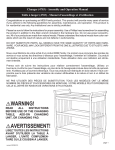
M/B Placement
Chapter 5
53
LABEL
54
COMPONENTS
1. CPU Socket
Supports the LGA1156 Intel Lynnfield/Havendale/Clarkdale processors
2. CPU_FAN
CPU cooling fan connector
3. DIMM1~4
240-Pin DDR3 SDRAM slots(Channel A: DIMM4, DIMM2 Channel B: DIMM3,
DIMM1) * Single Channel Mode: DIMM2 must be populated. * Dual Channel
Mode: DIMM2 and DIMM1 must be populated.
4. GPIO0~1
General Purpose I/O Signals
5. ATX1
Standard 24-pin ATX power connector
6. SPI_DEBUG
SPI debug header-factory use only
7. SATA1~6
Serial ATA connectors
8. F_PANEL
Front panel switch/LED header
9. F_USB3~4
Front panel USB headers
10. CLR_CMOS
Clear CMOS jumper
11. ME_DISABLE
ME disable jumper
12. F_USB2
Front panel USB header
13. F_USB1
Front panel USB header(Card Reader)
14. SPDIF_OUT1
SPDIF out header
15. F_AUDIO1
Front panel audio header
16. PCI1
32-bit add-on card slots
17. PCIE1X-1~2
PCI Express x1 slot
18. PCIE16X
PCI Express x16 slot
19. SYS_FAN
System cooling fan connector
20. ATX_12V
Auxiliary 4-pin power connector
Chapter 5
Jumper Setting
The section explains how to set jumper for correct configuration of the mainboard.
Setting Jumper
Use the motherboard jumpers to set system configuration options. Jumpers with more Than one pin are
numbered. When setting the jumpers, ensure that the jumper caps are Placed on the correct pins.
Checking Jumper Settings
The following illustration shows the location of the motherboard jumpers. Pin 1 is labeled.
Jumper
Type
Description
CLR_CMOSCLR_CMOS
3-pin
CLEAR CMOS
Setting (default)
1-2: NORMAL
2-3: CLEAR
Before clearing the
CMOS, make sure to
turn the system off.
CLR_CMOS
ME_DISABLE
MEDISABLE
1-2: NORMAL
2-3: MEDISABLE
ME_DISABLE
Chapter 5
55
Connecting Optional Devices
Refer to the following for information on connecting the motherboard’s optional devices:
SATA1~6: Serial ATA connectors
These connectors are used to support the new Serial ATA devices for the highest data
transfer rates (3.0 Gb/s), simpler disk drive cabling and easier PC assembly. It eliminates
limitations of the current Parallel ATA interface. But maintains register compatibility
and software compatibility with Parallel ATA.
Pin
Signal Name
?Pin
Signal Name
1
Ground
2
TX+
3
TX-
4
Ground
5
RX-
6
RX+
7
Ground
-
-
F_USB1~4: Front Panel USB headers
The motherboard has four USB ports installed on the rear edge I/O port array.
Additionally, some computer cases have USB ports at the front of the case. If you
56
Chapter 5
have this kind of case, use auxiliary USB connector to connect the front-mounted ports to the motherboard.
Pin
Signal Name
Function
1
USBPWR me
Front Panel USB Power
2
USBPWR
Front Panel USB Power
3
USB_FP_P0-
USB Port 0 Negative Signal
4
USB_FP_P1-
USB Port 1 Negative Signal
5
USB_FP_P0+
USB Port 0 Positive Signal
6
USB_FP_P1+
USB Port 1 Positive Signal
7
GND
Ground
8
GND
Ground
9
Key
No pin
10
USB_FP_OC0
NC
Please make sure that the USB cable has the same pin assignment as indicated
above. A different pin assignment may cause damage or system hang-up.
COM2: Onboard serial port header
Connect a serial port extension bracket to this header to add a second serial port to your system.
Pin
Signal Name
Function
1
DCD me
Data Carrier Detect
2
SIN
Serial Input
3
SOUT
UART B Serial Output
4
DTR
UART B Data Terminal Ready
5
GND
Ground
6
DSR
Data Set Ready
7
RTS
RART B Request to Send
8
CTS
Clear to Send
9
RI
Ring Indicator
10
NC
No pin
SPDIF_OUT1: SPDIF out header
This is an optional header that provides an SPDIF_OUT (Sony/Philips Digital Interface) output to digital
multimedia device through optical fiber or coaxial connector.
Chapter 5
57
Pin
Signal Name
Pin
Signal Name
1
+5V
2
KEY
3
SPDIF
4
GND
C_INTRUSION: Chassis detect header
This detects if the chassis cover has been removed. This function needs a chassis equipped with intrusion
detection switch and needs to be enabled in BIOS.
Pin
Signal Name
1
Caseopen
2
GND
INT_SPK1: Internal speaker
Pin
Signal Name
Pin
Signal Name
1
Output_L
2
GND
3
Output_R
4
Ground
5
GND
6
GND
7
N/A
8
VCC
OBR: Button recovery jumper
Pin
Signal Name
1
OBR
2
GND
PRINTER: Oboard parallel port header
Pin
58
Signal Name
Pin
Signal Name
1
STROBE
2
PD0
3
PD1
4
PD2
5
PD3
6
PD4
7
PD4
8
PD6
Chapter 5
Pin
Signal Name
Pin
Signal Name
9
PD7
10
ACK
11
BUSY
12
PE
13
SLCT
14
ALF
15
ERROR
16
INTT
17
SLCTIN
18
Ground
19
Ground
20
Ground
21
Ground
22
Ground
23
Ground
24
Ground
25
Ground
26
NC
TPM: TPM Module Header
This header allows user to protect the PC from impermissible visit.
Pin
Signal Name
Pin
Signal Name
1
CK_P_33M_T
PM
2
GND
3
FWH4
4
NC
5
PCIRST_L1
6
SMBDATA
7
PCIRST_L1
8
FWH2
9
VCC3
10
FWH1
11
FWH0
12
GND
13
NC
14
NC
15
3VSBY
16
SIRQ
17
GND
18
GND
19
LPCPD_L
20
SMBCLK
SPI_DEBUG: SPI_DEBUG header
Pin
Chapter 5
Signal Name
Pin
Signal Name
1
CS
2
WP Signal
Name
3
DI
4
HOLD
59
Pin
Signal Name
Pin
Signal Name
5
VCC
6
CLK
7
GND
8
DO
GPIO0~1: Button recovery jumper
Pin
60
Signal Name
1
GP36(GP16)
2
GND
Chapter 5
Chapter 6
FRU (Field Replaceable Unit) List
This chapter offers the FRU (Field Replaceable Unit) list in global configuration of the Aspire M5910(G)
desktop computer. Refer to this chapter whenever ordering the parts to repair or for RMA (Return Merchandise
Authorization).
NOTES:
chapter 6
•
When ordering FRU parts, check the most up-to-date information available on your regional web
or channel. For whatever reasons a part number is changed, it will NOT be noted on the printed
Service Guide. For Acer authorized service providers, your Acer office may have a different part
number code from those given in the FRU list of this printed Service Guide. You MUST use the
local FRU list provided by your regional Acer office to order FRU parts for service.
•
To scrap or to return the defective parts, follow the local government ordinance or regulations on
how to dispose it properly, or follow the rules set by your regional Acer office on how to return it.
•
This document will be updated as more information about the FRU list becomes available.
61
Aspire M5910(G) Exploded Diagram(AM551 ASSY)
NOTE: This section will be updated when more information becomes available.
ITEM
NAME
Q’TY
ITEM
NAME
Q’TY
1
CHASSIS ASM
1
5
FRONT BEZEL
1
2
TOP-COVER
1
6
HDD COVER
1
3
ODD
1
7
SIDE COVER
1
4
REMOVABLE HDD CARRIER
2
8
POWER
1
62
Chapter 6
Aspire M5910(G) Exploded Diagram(AM550 ASSY)
NOTE: This section will be updated when more information becomes available.
ITEM
NAME
Q’TY
ITEM
NAME
Q’TY
1
CHASSIS ASM
1
5
FRONT BEZEL
1
2
TOP-COVER
1
6
HDD COVER
1
3
ODD
1
7
SIDE COVER
1
4
REMOVABLE HDD CARRIER
2
8
POWER
1
Chapter 6
63
Aspire M5910(G) FRU List
Components
Model Name or Key Spec.
Acer P/N
MB Kit
MB Kit aSampras EIH57MK for M5 Intel H57 Realtek RTL8111E Giga
LAN ATX W/O 1394 LF w/i D-Sub port
MB.SDW07.002
Hon Hai Chassis MicroATX HM090H with front USB 4 port for Aspire
AM550 bezel
HS.13100.117
Hon Hai Chassis MicroATX HM090K w/i 3.5" carrierx2 w/i FIO USB 4 port
for Aspire AM551 bezel
HS.13100.124
Hon Hai Aspire Bezel AM550 USB 4 port bezel for HM090H chassis
PZ.11900.175
Hon Hai Aspire Bezel AM551 w/i 3,5"x2 carrier ,USB 4 port bezel for
HM090K chassis
PZ.11900.182
16-in-1 CR Realtek RTS-5181, 720mm USB cable, for 2010 M5
CR.10400.116
16-in-1 CR RI236 UT330-LK, 720mm USB cable, for 2010 M5
CR.10400.115
Cooler Intel LGA 1156 FXC PKP775G01U12 w/i duct
HI.10800.049
CM iCooler LGA1156 w/i pure al 93x93x40h w/i 9025 fan w/i 75mm duct
HI.10800.058
SYSTEM FAN KDE 1209/GP 92*92*25 (ROHS)
HI.S150F.002
FR 500W EUP 82+ (ES5.0)
PY.50008.004
FR 500W EUP 82+ (ES5.0)
PY.50008.005
FR 500W EUP 82+ (ES5.0)
PY.5000B.003
Chassis
Bezel
Card Reader
CPU Cooler
System Fan
Power Supply
64
Chapter 6
Components
Model Name or Key Spec.
Acer P/N
CPU
CPU Intel Core i7 870 LGA 2.93G 8M 1333 1156 95W B-1 Quad Core
KC.87001.CI7
CPU Intel Core i7 860 LGA 2.8G 8M 1333 1156 95W B-1 Quad Core
KC.86001.CI7
CPU Intel Core i5 750 LGA 2.66G 8M 1333 1156 95W B-1
KC.75001.CI5
CPU Intel Core i5 670 LGA 3.46G 4M 1333 1156 C-2 73W, Dual Core
KC.67001.CI5
CPU Intel Core i5 661 LGA 3.33G 4M 1333 1156 C-2 87W, Dual Core
KC.66101.CI5
CPU Intel Core i5 660 LGA 3.33G 4M 1333 1156 C-2 73W Dual Core
KC.66001.CI5
CPU Intel Core i5 650 LGA 3.2G 4M 1333 1156 C-2 73W, Dual Core
KC.65001.CI5
CPU Intel Core i3 540 LGA 3.06G 4M 1333 1156 73W C-2 Dual Core
KC.54001.CI3
CPU Intel Core i3 530 LGA 2.93G 4M 1333 1156 73W C-2 Dual Core
KC.53001.CI3
Pentium Dual Core G6950 (2.8G 2M 1066FSB)
KC.69501.DEG
M378B2873FHS-CH9 LF 128*8 46nm
KN.1GB0B.036
M378B5673FH0-CH9 LF 128*8 46nm
KN.2GB0B.024
GU502203EP0201 LF 128*8 0.065um
KN.1GB0H.015
GU512303EP0202 LF 128*8 0.065um
KN.2GB0H.009
75.073C1.G02 LF 128*8 0.065um
KN.1GB01.031
75.A73C1.G02 LF 128*8 0.065um
KN.2GB01.025
M378B2873EH1-CH9 LF 128*8 0.055um
KN.1GB0B.030
M378B5673EH1-CH9 LF 128*8 0.055um
KN.2GB0B.014
500
KH.50007.012
640
KH.64007.002
1T
KH.01K07.003
500
KH.50001.012
1T
KH.01K01.007
1.5TB
KH.15K01.002
500
KH.50008.014
640
KH.64008.003
1T (5400 RPM)
KH.01K08.005
1.5T(5400RPM)
KH.15K08.001
2T (5400 RPM)
KH.02K08.001
DH-16D5S Win7
KV.0160F.002
DH-20N(H/F) Win7
KV.0160D.016
Memory
HDD
DVD-ROM
Chapter 6
65
Components
Model Name or Key Spec.
Acer P/N
ODD TOSHIBA DVD-ROM HH DL 16X TS-H353C LF Black Bezel SATA
(HF+Win7)
KV.01601.001
GH-41F(H/F) Win7 non-Labelflash
KU.0160D.049
DH-16AASH (H/F) Win7 non-Labelflash
KU.0160F.009
ODD TOSHIBA Super-Multi DRIVE HH DL 16X TS-H653G LF Black
Bezel SATA (HF+Win7)
KU.01601.007
DH-4O3S Win7
KV.0040F.002
ODD HLDS BD COMBO HH 6X CH10N Black Bezel SATA w/ WIN7
KO.0060D.004
ODD HLDS BD COMBO HH 6X CH20N Black Bezel SATA HF + Win7
KO.0060D.005
DH-6E2S Win7 non-Labelflash
KO.0060F.002
ODD HLDS BD RW HH 6X BH30N Black Bezel SATA HF +Win7
KU.0060D.004
ODD HLDS BD RW HH 6X BH20F Black Bezel SATA (Win7 FW)
KU.0060D.005
NV GT340 1GB DDR5 DVI+HDMI+VGA ATX (HYNIX)
VG.PCPT3.401
NV GT330 2GB DDR2 DVI+HDMI+VGA ATX (SAMSUNG)
VG.PCPT3.301
NV GT330 2GB DDR2 DVI+HDMI+VGA ATX (HYNIX)
VG.PCPT3.302
NV GT320 1GB sDDR3 DVI+HDMI+VGA ATX (SAMSUNG)
VG.PCPT3.201
NV GT320 1GB sDDR3 DVI+HDMI+VGA ATX (HYNIX)
VG.PCPT3.202
NV 315 512MB sDDR3 DVI+HDMI+VGA ATX (SAMSUNG)
VG.PCPT3.151
NV 315 512MB sDDR3 DVI+HDMI+VGA ATX (HYNIX)
VG.PCPT3.152
GEFORCE 310 512MB DDR2 SAMSUNG (64BITS) VGA DVI HDMI ATX
BRACKET ROHS
VG.PCPT3.101
GEFORCE 310 512MB DDR2 HYNIX (64BITS) VGA DVI HDMI ATX
BRACKET ROHS
VG.PCPT3.102
HD5850 1GB (256BITS) GDDR5 SAMSUNG DVI DVI HDMI DP ATX
BRACKET ROHS
VG.A5850.001
HD5750 1GB GDDR 5 (128BITS) HYNIX DVI DVI HDMI DP W/ATX BKT
ROHS
VG.APC57.501
HD5570 1GB DDR 3 (128BITS) SAMSUNG DVI HDMI VGA W/ATX BKT
ROHS
VG.APC55.701
HD5450 512MB SDDR 3 (64BITS) SAMSUNG DVI HDMI VGA W/ATX
BKT ROHS
VG.APC54.501
Avermedia H751-A TV Tuner Card PCIe Hybrid ATSC, S/W Encoder
TU.10500.045
Avermedia H751-D TV Tuner Card PCIe Hybrid DVB-T, S/W Encoder
TU.10500.048
Avermedia A750 TV Tuner Card PCIe DMB-TH Digital, w/i external
antenna
TU.10500.063
VGA
TV-Tuner
Modem
66
Chapter 6
Components
Model Name or Key Spec.
Acer P/N
Lite-On PCI Modem card, D-1156I#/A7A, LSI Universal Modem (PCI)
56K V.92 - Pinball (P40)
FX.10100.004
WP81R1, WLAN PCI Card 802.11b/g/n 1T x 2R, Realtek RTL8190
NI.10200.021
WN7600R, WLAN PCI-Ex1 card 802.11 b/g/n 1T x 2R, Ralink 1T x 2R,
RT2790+RT2720
NI.10200.008
WN7601R, Ralink RT3090, 802.11b/g/n 1x1 WLAN PCI-E x1 card
NI.10200.037
Lite-on Optical mouse USB SM-9625 with new color AC-MT-018
MS.11200.048
Chicony RF2.4 MG-0766 with new silver color
MS.11200.054
Lite-on Optical mouse USB SM-9625S new silver color AC-MT-113
MS.11200.068
Chicony wireless mouse RF2.4 MG-0766 new silver color AC-MT-113
MS.11200.069
Neosonica Speaker Acer logo /LF /0810 / 9M-20A200-000
SP.10600.011
Neosonica speaker USB new silver color AC-MT-113
SP.10600.035
Keyboard LITE-ON SK-9625S USB 104KS Silver US new silver color ACMT-113
KB.USB0B.203
Keyboard LITE-ON SK-9625S USB 104KS Silver US new silver color ACMT-113
KB.USB0B.242
Keyboard CHICONY KU-0760 USB Standard 104KS Black US w/o eKey
KB.USB03.192
Keyboard CHICONY KU-0760 USB Standard 104KS Black US w/o eKey
KB.USB03.311
Keyboard LITE-ON SK-9625 USB Standard 104KS Black US w/o eKey
KB.USB0B.158
Keyboard LITE-ON SK-9625 USB Standard 104KS Black US w/o eKey
KB.USB0B.202
WLAN
Mouse
External Speaker
KB
Chapter 6
67