1
Acer
Aspire M3802(G) Service Guide
Service guide files and updates are available
on the ACER/CSD web; for more information,
please refer to http://csd.acer.com.tw
PRINTED IN TAIWAN
Revision History
Please refer to the table below for the updates made on this service guide.
Date
ii
Chapter
Updates
Copyright
Copyright © 2009 by Acer Incorporated. All rights reserved. No part of this publication may be reproduced,
transmitted, transcribed, stored in a retrieval system, or translated into any language or computer language, in
any form or by any means, electronic, mechanical, magnetic, optical, chemical, manual or otherwise, without
the prior written permission of Acer Incorporated.
iii
Disclaimer
The information in this guide is subject to change without notice.
Acer Incorporated makes no representations or warranties, either expressed or implied, with respect to the
contents hereof and specifically disclaims any warranties of merchantability or fitness for any particular
purpose. Any Acer Incorporated software described in this manual is sold or licensed "as is". Should the
programs prove defective following their purchase, the buyer (and not Acer Incorporated, its distributor, or its
dealer) assumes the entire cost of all necessary servicing, repair, and any incidental or consequential
damages resulting from any defect in the software.
Acer is a registered trademark of Acer Corporation.
Intel is a registered trademark of Intel Corporation.
Pentium Dual-Core, Celeron Dual-Core, Core 2 Duo, Core 2 Quad, Celeron, and combinations thereof, are
trademarks of Intel Corporation.
Other brand and product names are trademarks and/or registered trademarks of their respective holders.
iv
Conventions
The following conventions are used in this manual:
SCREEN
MESSAGES
Denotes actual messages that appear on screen.
NOTE
Gives additional information related to the current topic.
WARNING
Alerts you to any physical risk or system damage that might result from doing
or not doing specific actions.
CAUTION
Gives precautionary measures to avoid possible hardware or software
problems.
IMPORTANT
Reminds you to do specific actions relevant to the accomplishment of
procedures.
v
Service Guide Coverage
This Service Guide provides you with all technical information relating to the BASIC CONFIGURATION
decided for Acer's "global" product offering. To better fit local market requirements and enhance product
competitiveness, your regional office MAY have decided to extend the functionality of a machine (e.g. add-on
card, modem, or extra memory capability). These LOCALIZED FEATURES will NOT be covered in this generic
service guide. In such cases, please contact your regional offices or the responsible personnel/channel to
provide you with further technical details.
FRU Information
Please note WHEN ORDERING FRU PARTS, that you should check the most up-to-date information available
on your regional web or channel. If, for whatever reason, a part number change is made, it will not be noted in
the printed Service Guide. For ACER-AUTHORIZED SERVICE PROVIDERS, your Acer office may have a
DIFFERENT part number code to those given in the FRU list of this printed Service Guide. You MUST use the
list provided by your regional Acer office to order FRU parts for repair and service of customer machines.
vi
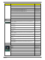
Table of Contents
System Tour
Features
Block Diagram
System Components
Front Panel
Rear Panel
Hardware Specifications and Configurations
Power Management Function(ACPI support function)
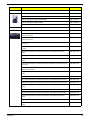
System Utilities
CMOS Setup Utility
Entering CMOS setup
Navigating Through the Setup Utility
Setup Utility Menus
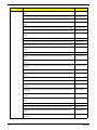
System Disassembly
Disassembly Requirements
Pre-disassembly Procedure
Removing the Side Panel
Removing the Heat Sink Fan Assembly
Removing the Processor
Removing the Mode Card
Removing the TV Card
Removing the VGA Card
Removing the Hard Disk Drive
Removing the Front Bezel
Removing the Optical Drive
Removing Cables
Removing the Power Supply
Removing the Memory Modules
Removing the Mainboard
System Troubleshooting
Power-On Self-Test (POST)
POST Error Messages List
Error Symptoms List
Undetermined Problems
Jumper and Connector Information
M/B Placement
Jumper Setting
FRU (Field Replaceable Unit) List
Aspire M3802 Exploded Diagram
Aspire M3802 FRU List
Intel RAID SOP
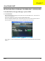
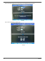
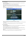
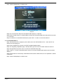
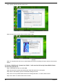
INTEL® MATRIX STORAGE TECHNOLOGY CHECK(DOS)
1.Intel(R) Matrix Storage Manager option ROM
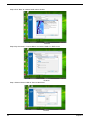
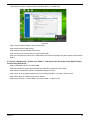
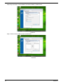
Intel RAID SOP (Windows for WIN7)
2.Intel(R) Matrix Storage Console
1
1
4
5
5
6
7
10
11
11
12
12
13
25
25
26
27
28
29
30
31
31
31
34
35
36
38
39
40
41
44
47
54
60
61
61
63
71
72
74
83
83
83
89
89
vii
Chapter 1
System Tour
Features
Below is a brief summary of the computer’s many feature:
NOTE: The features listed in this section is for your reference only. The exact configuration of the system
depends on the model purchased.
Operating System
•
Microsoft Windows Windows7 Home Premium 64bits
•
Microsoft Windows Windows7 Home Premium 32bits
•
Microsoft Windows Windows7 Home Basic 32bits
•
Linpus Linux x-Window mode
•
Freedos
Processor
•
Socket Type: Intel Socket T LGA 775 pin
•
Socket Quantity: 1
•
Processor Type:
•
•
CPUs which compliant with Intel FSB 800/1066/1333 MHz CPUs
FMB
•
95W FMB
•
VRD 11.1
Chipset
•
GMCH: Intel G43
•
ICH: Intel ICH10R
•
Design Criteria:
•
•
Should meet Intel G43+ICH10R platform design guide
Super I/O: ITE8720
•
Should support Intel ASFC
•
Should support Intel PECI
PCB
•
MicroATX (9.6 inches*9.6inches, 244mm*244mm)
Memory subsystem
•
Socket Type: DDR II connector
•
Socket Quantity: 4
•
Channel A: slot 0, 1; Channel B: slot 2, 3
•
Different colors for slot 0/2 and slot 1/3
•
Dual channel support
•
Support Intel Flex Memory Mode
Chapter 1
1
•
•
Capacity support:
•
1GB / 2GB DDRII 667/800 Un-buffered Non-ECC DIMM support
•
1GB to 8GB Max memory support
Design Criteria:
•
•
Should meet Intel G43 Express Chipset platform design guide
Dual channel should be enabled always when plug-in 2 same memory size DDRII memory
module
Hard disk
•
Support up to two SATA ports
•
3.5", 25.4mm
•
Capacity and models are listed on AVLC
Optical disk
•
Support two SATA 5.25" standard ODD
•
Support DVD-ROM, DVD-SuperMulti, BD-combo, BD-rewrite
•
Maximum ODD depth to 185mm with bezel
•
Models are listed on AVLC
Graphics card
•
No mechanical retriction to support for double slot, full length graphics cards in the single PSIe X16 slot
On-Board Graphic solution
•
Intel G43 on die graphic solution
•
DVMT 5.0 technology support
•
Enhanced 3D and Clear Video technology support
•
1 D-sub VGA port on rear
•
1 HDMI port on rear
•
Dual View function support
Serial ATA controller
•
Slot Type: SATA connector
•
Six SATA ports:
•
•
4 for HDD
•
2 for ODD
Storage Type support:
1.HDD : Support RAID 0/1/5/10
2.CD-ROM/CD-RW/DVD-ROM/DVD-RW/DVD+RW/DVD Dual/DVD SuperMultiPlus/Blu-Ray ODD
3.AHCI mode supported for internal SATA port
Audio
2
•
Chip : HD audio codec ALC888S-VC codec 7.1
•
Connectors support:
•
Rear 6 jack follow HD audio definition
•
Audio jacks color coding: should meet Microsoft Windows Logo Program Device Requirements:
Audio-0002
Chapter 1
•
2 S/PDIF-out header (1*4) for ALC888S-VC sku
•
1 front panel audio header (2*5)
LAN
•
MAC Controller: ICH10R
•
PHY: Intel Boazman 82567V PCI-E Giga LAN
USB ports
•
Controller: Intel ICH10R
•
Ports Quantity: 12
•
•
4 back panel ports
•
On-board: 4 2*5 headers ( 8 ports)
•
4 ports for front daughter board
•
Connector Pin: standard Intel FPIO pin definition
Data transfer rate support: USB 2.0/1.1
Extension slot
•
Support one PCIe x 16 slot
•
Support two PCIe x 1 slots
•
Support one PCIe x 2 slot
Total I/O ports
•
1 PS/2 Keyboard port,
•
1 PS/2 Mouse port
•
1 D-Sub VGA port
•
1 HDMI VGA port
•
1 RJ45 LAN port
•
1 1394 port
•
4 USB ports
•
7.1 channel phone jack
•
One HD headphone output in front bezel
•
One MIC-IN in front bezel
•
Multi-in-1 card reader (SD , MMC , Mini-SD , Micro-SD (T-flash) , RS-MMC, Mobile -MMC ,MMC-micro,
MS , MS-PRO , MS Duo , MS-PRO Due , Micro-MS(M2), xD type M and Type H card, CF type I and II,
Microdrive)
System BIOS
•
Size: 2Mb
Use SPI Flash
•
AMI Kernel with Acer skin
Power supply
•
500W/300W/250W in stable mode
•
Active PFC 220V for EMEA and China
•
Non-PFC 110V and 220V with select switch.
•
Active PFC 220V with Energy Star 5.0
Chapter 1
3
Block Diagram
4
Chapter 1
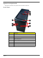
System Components
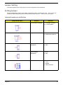
This section is a virtual tour of the system’s interior and exterior components.
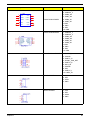
Front Panel
11
10
9
1
8
7
2
3
4
6
5
Chapter 1
No.
Component
1
Acer logo
2
XD(XD-PICTURE) slot
3
Micro SD/M2 slot
4
CF I/II (CompactFlash Type I/II) slot
5
Memory stick PRO slot
6
SD(Secure Digital) solt
7
Optical drive button
8
Power button
9
USB 2.0 ports
10
Headphone/Speaker-out/line-out jack
11
Microphone-in jack
5
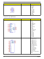
Rear Panel
1
19
18
2
3
17
4
16
5
6
7
8
15
12
14
11
13
10
9
6
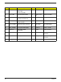
No.
Component
1
Power connector
2
PS2 keyboard port
3
VGA port
4
HDMI port
5
USB 2.0 ports
6
Side Surround
7
Surround
8
Mic-in
9
Expansion slot (graphics card and TV tuner card and Mode card)
10
Line-in
11
Line-out
12
Center speaker/subwoofer jack
13
USB 2.0 ports
14
S/PDIF port
15
LAN connector
16
1394 port
17
System FAN
18
PS2 mouse port
19
Fan aperture
Chapter 1
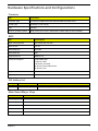
Hardware Specifications and Configurations
Processor
Item
Specification
Processor Type
CPUs which complaint with Intel FSB 800/1066/1333 MHz CPUs
Socket Type
Intel Socket T LGA 755 pin
FSB
1333 MHz
Minimum operating speed
0 MHz (If Stop CPU Clock in Sleep State in BIOS Setup is set to Enabled.)
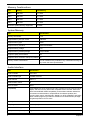
BIOS
Item
Specification
BIOS code programer
AMI Kernel with Acer skin
BIOS version
P01-A0
BIOS ROM type
SPI ROM
BIOS ROM size
2Mb
Support protocol
SMBIOS 2.5
Device Boot Support
Support BBS spec
1st priority: HDD
2nd priority: CD-ROM
3th priority: Removable Device
4th priority: LAN
Support to LS-120 drive
YES
Support to BIOS boot block feature YES
IOS Hotkey List
Hotkey
Function
Description
Del
Enter BIOS Setup Utility
Press while the system is booting to enter BIOS Setup Utility.
Main Board Major Chips
Item
Specification
North Bridge
Intel G43
South Bridge
Intel ICH10R
Audio controller
HD Audio codec ALC888S-VS
LAN controller
MAC controller: Intel ICH10R / PHY: Intel Boazman 82567V PCI-E Giga LAN
HDD controller
Intel ICH10R
Chapter 1
7
Memory Combinations
Slot
Memory
Total Memory
Slot 1
1MB,2GB
1G ~2GB
Slot 2
1MB,2GB
1G ~2GB
Slot 3
1MB,2GB
1G ~2GB
Slot 4
1MB,2GB
1G ~2GB
Maximum System Memory Supported
1G~8GB
System Memory
Item
Specification
Memory slot number
4 slot
Support Memory size per socket
1GB/2GB
Support memory type
DDRII
Support memory interface
DDRII 667/800MHz
Support memory voltage
1.5V
Support memory module package
240-pin DDRII
Support to parity check feature
Yes
Support to error correction code (ECC) feature No
Memory module combinations
You can install memory modules in any combination as long as
they match the above specifications.
Audio Interface
Item
Specification
Audio controller
Intel ICH10
Audio controller type
ALC8862-VC2-GR
Audio channel
codec 5.1
Audio function control
No
Mono or stereo
Stereo
Compatibility
The ALC888S-VC series support host audio controller from the Intel ICH series
chipset, and also from any other HDA compatible audio controller. With EAX/
Direct Sound 3D/I3DL2/A3D compatibility, and excellent software utilities like
environment sound emulation, multiple bands of software equalizer and
dynamic range control, optional Dolby, Digital Live, DTS CONNECT, and Dolby
Home Theater programs, provides an excellent home entertainment package
and game experience for PC users.
Music synthesizer
No
Sampling rate
192KHz (max)
MPU-401 UART support
No
Microphone/Headphone jack
Supported
8
Chapter 1
SATA Interface
Item
Specification
SATA controller
JMB362-QGEZ0A
SATA controller resident bus
PCI bus
Number of SATA channel
SATA X 6
Support bootable CD-ROM
YES
USB Port
Item
Specification
Universal HCI
USB 2.0/1.1
USB Class
Support legacy keyboard for legacy mode
USB Connectors Quantity
6 back real ports
4 top bezel ports
2 ports for media card reader
Environmental Requirements
Item
Specification
Temperature
Operating
+5°C ~ +35°C
Non-operating
-20 ~ +60°C (Storage package)
Humidity
Operating
15% to 80% RH
Non-operating
10% to 90% RH
Vibration
Operating (unpacked)
5 ~ 500 Hz: 2.20g RMS random, 10 minutes per axis in all 3 axes.
5 ~500 Hz: 1.09g RMS random, 1 hour per axis in all 3 axes.
Power Management
Devices
S1
S3
S4
S5
Power Button
V
V
V
V
USB Keyboard/Mouse
V
V
N/A
N/A
PME
Disabled
Disabled
Disabled
Disabled
RCT
Disabled
Disabled
Disabled
Disabled
WOR
Disabled
Disabled
Disabled
Disabled
•
Devices wake up from S3 should be less than.
•
Devices wake up from S5 should be less than 10 seconds.
Chapter 1
9
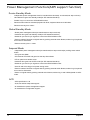
Power Management Function(ACPI support function)
Device Standby Mode
•
Independent power management timer for hard disk drive devices(0-15 minutes,time step=1minute).
•
Hard Disk drive goes into Standby mode(for ATA standard interface).
•
Disable V-sync to control the VESA DPMS monitor.
•
Resume method:device activated (keyboard for DOS, keyboard &mouse for Windows.
•
Resume recovery time 3-5sec
Global Standby Mode
•
Global power management timer(2-120minutes,time step=10minute).
•
Hard disk drive goes into Standby mode(for ATA standard interface).
•
Disable H-sync and V-sync signals to control the VESA DPMS monitor.
•
•
Resume method: Resume to original state by pushing external switch Button,modem ring in,keyboard
an mouse for APM mode.
Resume recovery time :7-10sec
Suspend Mode
•
Independent power management timer(2-120minutes,time step=10minute)or pushing extern switch
button.
•
CPU goes into SMM
•
CPU asserts STPCLK# and goes into the Stop Grant State.
•
LED on panel turns amber colour.
•
Hard disk drive goes into SLEEP mode (for ATA standard interface).
•
Disable H-sync and V-sync signals to control the VESA DPMS monitor.
•
Ultra I/O and VGA chip go into power saving mode.
•
Resume method: Resume to original state by pushing external switch Button,modem ring in,keyboard
an mouse for APM mode
•
Return to original state by pushing external switch button,modem ring in and USB keyboard for ACPI
mode.
ACPI
10
•
ACPI specification 1.0b
•
S0,S1,S2 and S5 sleep state support.
•
On board device power management support.
•
On board device configuration support.
Chapter 1
Chapter 2
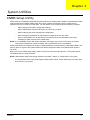
System Utilities
CMOS Setup Utility
CMOS setup is a hardware configuration program built into the system ROM, called the complementary metaloxide semiconductor (CMOS) Setup Utility. Since most systems are already properly configured and
optimized, there is no need to run this utility. You will need to run this utility under the following conditions.
•
When changing the system configuration settings
•
When redefining the communication ports to prevent any conflicts
•
When modifying the power management configuration
•
When changing the password or making other changes to the security setup
When a configuration error is detected by the system and you are prompted ("Run Setup"
message) to make changes to the CMOS setup
NOTE: If you repeatedly receive Run Setup messages, the battery may be bad. In this case, the system
cannot retain configuration values in CMOS. Ask a qualified technician for assistance.
•
CMOS setup loads the configuration values in a battery-backed nonvolatile memory called CMOS RAM. This
memory area is not part of the system RAM which allows configuration data to be retained when power is
turned off.
Before you run the CMOS Setup Utility, make sure that you have saved all open files. The system reboots
immediately after you close the Setup.
NOTE: CMOS Setup Utility will be simply referred to as “BIOS”, "Setup", or "Setup utility" in this guide.
The screenshots used in this guide display default system values. These values may not be the same
those found in your system.
Chapter 2
11
Entering CMOS setup
1.
Turn on the server and the monitor.
If the server is already turned on, close all open applications, then restart the server.
2.
During POST, press Delete.
If you fail to press Delete before POST is completed, you will need to restart the server.
The Setup Main menu will be displayed showing the Setup’s menu bar. Use the left and right arrow keys
to move between selections on the menu bar.
Navigating Through the Setup Utility
Use the following keys to move around the Setup utility.
•
Left and Right arrow keys – Move between selections on the menu bar.
•
Up and Down arrow keys – Move the cursor to the field you want.
•
PgUp and PgDn keys – Move the cursor to the previous and next page of a multiple page menu.
•
Home – Move the cursor to the first page of a multiple page menu.
•
End – Move the cursor to the last page of a multiple page menu.
+ and - keys – Select a value for the currently selected field (only if it is user-configurable). Press
these keys repeatedly to display each possible entry, or the Enter key to choose from a pop-up
menu.
NOTE: Grayed-out fields are not user-configurable.
•
•
Enter key – Display a submenu screen.
NOTE: Availability of submenu screen is indicated by a (>).
•
12
Esc – If you press this key:
•
On one of the primary menu screens, the Exit menu displays.
•
On a submenu screen, the previous screen displays.
•
When you are making selections from a pop-up menu, closes the pop-up without making a
selection.
•
F1 – Display the General Help panel.
•
F6 – Press to load optimized default system values.
•
F7 – Press to load fail-safe default system values.
•
F10 – Save changes made the Setup and close the utility.
Chapter 2
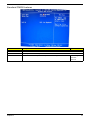
Setup Utility Menus
The Setup Main menu includes the following main setup categories.
Parameter
Description
Product Information
This page shows the relevant information of the main board
Standard CMOS Features
This setup page includes all the items in standard compatible BIOS
Advanced BIOS Features
This setup page includes all the items of Award special enhanced features
Advanced Chipset Features
This setup page includes all advanced chipset features
Integrated Peripherals
This setup page includes all onboard peripherals
Power Management Setup
This setup page includes all the items of Green function features
PC Health Status
This setup page is the System auto detect Temperature, voltage, and fan speed
Frequency/Voltage Control
This setup page is the System Frequency setup
BIOS Security Features
Change, set or disable password. It allows you to limit access to the System
Load Default Setting
Load Default Setting indicates the value of the system parameters which the system would be
in best performance configuration
Save & Exit Setup
Save CMOS value settings to CMOS and exit setup
Exit Without Saving
Abandon all CMOS value changes and exit setup
In the descriptive table following each of the menu screenshots, settings in boldface are the default and
suggested settings.
Chapter 2
13
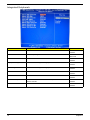
Product Information
The Product Information menu displays basic information about the system. These entries are for your
reference only and are not user-configurable.
Parameter
Description
Processor Type
Type of CPU installed on the system.
Processor Speed
Speed of the CPU installed on the system.
System Memory
Total size of system memory installed on the system.
Product Name
Product name of the system.
System Serial Number
Serial number of the system.
System BIOS Version
Version number of the BIOS setup utility.
BIOS Release Date
Date when the BIOS setup utility was released
Asset Tag Number
Asset tag number of this system.
14
Chapter 2
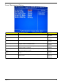
Standard CMOS Features
Parameter
Description
System Date
Set the date following the weekday-month-day-year format.
System Time
Set the system time following the hour-minute-second format.
Halt On
Determines whether the system will stop for an error during the POST.
Option
All, But Keyboard
No Errors
All Errors
Chapter 2
15
Advanced BIOS Feature
Parameter
Description
Option
Quick Boot
Allows you to decrease the time it takes to boot the computer by shortening
or skipping certain standard booting process.
Enabled
Quiet Boot
When enabled, the BIOS splash screen displays during startup.
Enabled
When disabled, the diagnostic screen displays during startup.
Disabled
Specifies the boot order from the available devices.
Hard Disk
1st/2nd/3rd/4th Boot Device
Disabled
CD^DVD
Removable
Device
LAN
Hard Disk Drive Priority
Press Enter to access the Hard Disk Drive Priority submenu and specify the boot device
priority sequence from available hard drives.
Optical Disk Drives Priority
Press Enter to access the Optical Disk Drive Priority submenu and specify the boot device
priority sequence from available CD/DVD drives.
Removable Device Priority
Press Enter to access the Removable Device Priority submenu and specify the boot device
priority sequence from available removable drives.
Bootup Num-Lock
Selects power on state for Num Lock.
USB Beep Message
Enables or disables BIOS to display error beeps or messages during USB
device enumeration.
On
Off
16
Disabled
Enabled
Chapter 2
Advanced Chipset Features
Parameter
Description
Option
Intel EIST
When enabled, this feature allows the OS to reduce power consumption.
Enabled
When disabled, the system operates at maximum CPU speed.
Disabled
When enabled, the processor disables code execution when a worm
attempts to insert a code in the buffer preventing damage and worm
propagation.
Enabled
Intel XD Bit
Disabled
When disabled, the processor forces the Execute Disable (XD) Bit feature
flag to always return to 0.
Intel VT
Enables or disables the Virtualization Technology (VT) availability. If
enabled, a virtual machine manager (VMM) can utilize the additional
hardware virtualization capabilities provided by this technology.
Enabled
Disabled
Note: A full reset is required to change the setting.
Memory Hole Remapping
Primary Video
Enables or disables remapping of overlapped PCI memory above the total
physical memory.
Enabled
Select a graphic controller as a primary boot device.
Auto
Disabled
PCIE
Onboard VGA
Chapter 2
17
Integrated Peripherals
Parameter
Description
Onboard SATA Controller
Enables or disables the onboard SATA controller.
Option
Enabled
Disabled
Onboard SATA Mode
Select an operating mode for the onboard SATA.
RAID
Native IDE
Onboard USB Controller
Enables or disables the onboard USB controller.
Legacy USB Support
Enables or disables support for legacy USB devices.
Enabled
Disabled
Enabled
Disabled
USB Storage Emulation
Enables or disables support for legacy USB devices.
Onboard Audio Controller
Enables or disables the onboard audio controller.
Enabled
Disabled
Enabled
Disabled
Onboard LAN Controller
Enables or disables the onboard LAN controller.
Enabled
Onboard LAN Option ROM
Enables or disables the load of embedded option ROM for onboard
network controller.
Enabled
Enables or disables the onboard 1394 controller.
Enabled
Disabled
Onboard 1394 Controller
Disabled
Disabled
18
Chapter 2
Power Management Setup
Parameter
Description
Option
ACPI Suspend Mode
Select an ACPI state.
S3 (STR)
Deep power off mode
Select the Deep power off Mode
S1 (POS)
Enabled
Disabled
Power On by RTC Alarm
Enables or Disables to wake up the system by RTC Alarm Function
Enabled
Power On by PCIE Devices
Enables or disables to wake up the system from a power saving mode
through an event on PCI Express device.
Enabled
Power On by PCI Devices
Enables or disables to wake up the system from a power saving mode
through an event on PCI device.
Enabled
Wake Up by PS/2 KB/
Mouse
Enables or disables to wake up the system from a power saving mode
using a PS2 keyboard or mouse.
Enabled
Wake Up by USB KB/
Mouse
If enabled, press any key or click the mouse will wake system from S1/
S3 state.
Enabled
Restore On AC Power Loss
Enables or disables the system to reboot after a power failure or
interrupt occurs.
Power Off
Disabled
Disabled
Disabled
Disabled
Disabled
Power On
Last State
Chapter 2
19
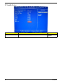
PC Health Status
Parameter
Description
Option
Smart FAN
Enables or disables the smart system fan control function.
Enabled
Disabled
20
Chapter 2
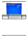
Frequency/Voltage Control
Parameter
Description
Option
Enable Clock to All DIMM/
PCI
Enables or disables control the clock to all DIMM/PCI
Enabled
Spread Spectrum
Chapter 2
Disabled
Enables or disables the reduction of the mainboard’s EMI.
Enabled
Note: Remember to disable the Spread Spectrum feature if you are
overclocking. A slight jitter can introduce a temporary boost in clock
speed causing the overclocked processor to lock up.
Disabled
21
BIOS Security Features
Parameter
Description
Supervisor Password
Indicates the status of the supervisor password.
User Password
Indicates the status of the user password.
Change Supervisor
Password
Supervisor password prevents unauthorized access to the BIOS Setup Utility.
Press Enter to change the Supervisor password.
Setting a supervisor password
1.
Use the up/down arrow keys to select Change Supervisor Password menu then press Enter.
A password box will appear.
2.
Type a password then press Enter.
The password may consist up to six alphanumeric characters (A-Z, a-z, 0-9)
3.
Retype the password to verify the first entry then press Enter again.
4.
Press F10.
5.
Select Yes to save the new password and close the Setup Utility.
Changing the supervisor password
1.
Use the up/down arrow keys to select Change Supervisor Password menu then press Enter.
2.
Type the original password then press Enter.
3.
Type a new password then press Enter.
4.
Retype the password to verify the first entry then press Enter again.
5.
Press F10.
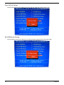
6.
Select Yes to save the new password and close the Setup Utility.
Removing a supervisor password
22
1.
Use the up/down arrow keys to select Change Supervisor Password menu then press Enter.
2.
Enter the current password then press Enter.
3.
Press Enter twice without entering anything in the password fields.
Chapter 2
Load Default Settings
The Load Default Settings menu allows you to load the default settings for all BIOS setup parameters. Setup
defaults are quite demanding in terms of resources consumption. If you are using low-speed memory chips or
other kinds of low-performance components and you choose to load these settings, the system might not
function properly.
Chapter 2
23
Save & Exit Setup
The Save & Exit Setup menu allows you to save changes made and close the Setup Utility.
Exit Without Saving
The Exit Without Saving menu allows you to discard changes made and close the Setup Utility.
24
Chapter 2
Chapter 3
System Disassembly
This chapter contains step-by-step procedures on how to disassemble the desktop computer for maintenance
and troubleshooting.
Disassembly Requirements
To disassemble the computer, you need the following tools:
•
Wrist grounding strap and conductive mat for preventing electrostatic discharge
•
Flat-blade screwdriver
•
Philips screwdriver
•
Hex screwdriver
•
Plastic flat-blade screwdriver
•
Plastic tweezers
NOTE: The screws for the different components vary in size. During the disassembly process, group the
screws with the corresponding components to avoid mismatch when putting back the components.
Chapter 3
25
Pre-disassembly Procedure
Before proceeding with the disassembly procedure, perform the steps listed below:
26
1.
Turn off the system and all the peripherals connected to it.
2.
Unplug the power cord from the power outlets.
3.
Unplug the power cord from the system.
4.
Unplug all peripheral cables from the system.
5.
Place the system unit on a flat, stable surface.
Chapter 3
Removing the Side Panel
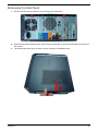
1.
Remove the two screws located on the rear edge of the side panel.
2.
Slide the side panel toward the back of the chassis until the tabs on the cover disengage with the slots on
the chassis.
3.
Lift the side panel away from the server and put it aside for reinstallation later.
Chapter 3
27
Removing the Heat Sink Fan Assembly
WARNING:The heat sink becomes very hot when the system is on. NEVER touch the heat sink with any metal
or with your hands.
28
1.
disconnect the fan cable from the mainboard.
2.
Use a long-nosed screwdriver to loosen the four screws on the heat sink, in the order as shown below.
3.
Lift the heat sink fan assembly away from the mainboard.
Chapter 3
Removing the Processor
IMPORTANT:Before removing a processor from the mainboard, make sure to create a backup file of all
important data.
WARNING:The processor becomes very hot when the system is on. Allow it to cool off first before handling.
1.
Release the load lever (1).
2.
Pull the load lever to the fully open, upright position (2) and lift the load plate (3).
3.
Pull out the processor from the socket.
IMPORTANT: If you are going to install a new processor, note the arrow on the corner to make sure the
processor is properly oriented over the socket
Chapter 3
29
Removing the Mode Card
30
1.
Release the Slot cover lock.
2.
Remove the screw from chassis.
3.
Gently pull the Modem card to remove it from the mainboard.
Chapter 3
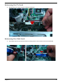
Removing the TV Card
1.
Gently pull the TV card to remove it from the mainboard.
Removing the VGA Card
1.
One finger Press the clip and the same time Gently pull the card to remove it from the mainboard.
Chapter 3
31
Removing the Hard Disk Drive
32
1.
Disconnect the data and power cables from the rear of the optical drive and the mainboard.
2.
Remove the HDD bracket
a.
Remove the screw that secures the HDD bracket to the ODD bracket.
b.
Lift the bracket up and turn it over.
Chapter 3
3.
Remove the HDD module
a.
Remove the eight screws secure the HDD module to the HDD bracket.
b.
Slide the HDD out of the bracket.
Chapter 3
33
Removing the Front Bezel
34
1.
Disconnect the LED cable.
2.
Release the Cable Clip. Disconnect the Power-led Cable.
3.
Release the front bezel from the chassis interior.
4.
Pull the bezel away from the chassis.
Chapter 3
Removing the Optical Drive
1.
Disconnect the data and power cables from the rear of the optical drive.
Power cabl e
2.
Remove Four screw from the optical drive.
3.
Pull the drive out of the drive.
Chapter 3
Dat a cabl e
35
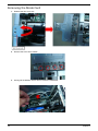
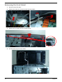
Removing the Cables
1.
Remove HDD Data and ODD Data cables from slot of M/B.
Powe- Led Cabl e
HDD Cabl e
ODD Cabl e
Remove USB1/2/3 cable from M/B.
3.
Remove Card reader cable and Audio cable from M/B
Fr ont Audi o Cabl e
Fr ont USB Cabl e ( USB1)
2.
Fr ont USB Cabl e ( USB2)
36
Rear I O USB Cabl e ( USB2)
Rear SPDI F Cabl e
Chapter 3
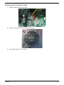
Removing the System FAN
1.
Remove System FAN cable from M/B.
2.
Release four screws according to the following picture.
3.
Take off the system fan from chassis.
Chapter 3
37
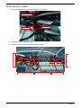
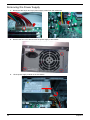
Removing the Power Supply
38
1.
Disconnect the 24-pin and 4-pin power supply cables from the mainboard.
2.
Remove the four screw that secures the power supply to the chassis.
3.
Lift the power supply module out of the chassis.
Chapter 3
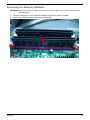
Removing the Memory Modules
IMPORTANT:Before removing any DIMM from the memory board, make sure to create a backup file of all
important data.
1.
Press the holding clips on both sides of the DIMM slot outward to release the DIMM.
2.
Gently pull the DIMM upward to pull it away from the M/B.
Chapter 3
39
Removing the Mainboard
40
1.
Remove the eight screws that secure the mainboard to the chassis.
2.
Lift the board from the chassis.
Chapter 3
Chapter 4
System Troubleshooting
Please refer to generic troubleshooting guide for troubleshooting information relating to following topics:
Chapter 4
•
Power-On Self-Test (POST)
•
POST Check Points
•
POST Error Messages List
•
Error Symptoms List
41
Power-On Self-Test (POST)
Each time you turn on the system, the Power-on Self Test (POST) is initiated. Several items are tested during
POST, but is for the most part transparent to the user.
The Power-On Self Test (POST) is a BIOS procedure that boots the system, initializes and diagnoses the
system components, and controls the operation of the power-on password option. If POST discovers errors in
system operations at power-on, it displays error messages on screen, generates a check point code at port
80h or even halts the system if the error is fatal.
NOTE: When Post executes a task, it uses a series of preset numbers called check points to belatched atport
80h, indicating the stages it is currently running. This latch can be read and shown on a debug
board.The following table describes the BIOS common tasks carried out by POST. Each task is denoted
by an unique check point number. For other unique check point numbers that are not listed in the table,
refer to the corresponding product service guide.
Post Checkpoints List: The list may vary accordingly depending on your BIOS
Bootblock Initialization Code Checkpoints
Checkpoint
Description
Before D0
If boot block debugger is enabled, CPU cache-as-RAM functionality is enabled at this
point. Stack will be enabled from this point.
D0
Early Boot Strap Processor (BSP) initialization like microcode update, frequency and other
CPU critical initialization. Early chipset initialization is done.
D1
Early super I/O initialization is done including RTC and keyboard controller. Serial port is
enabled at this point if needed for debugging. NMI is disabled. Perform keyboard controller
BAT test. Save power-on CPUID value in scratch CMOS. Go to flat mode with 4GB limit
and GA20 enabled.
D2
Verify the boot block checksum. System will hang here if checksum is bad.
D3
Disable CACHE before memory detection. Execute full memory sizing module. If memory
sizing module not executed, start memory refresh and do memory sizing in Boot block
code. Do additional chipset initialization. Re-enable CACHE. Verify that flat mode is
enabled.
D4
Test base 512KB memory. Adjust policies and cache first 8MB. Set stack.
D5
Bootblock code is copied from ROM to lower system memory and control is given to it.
BIOS now executes out of RAM. Copies compressed boot block code to memory in right
segments. Copies BIOS from ROM to RAM for faster access. Performs main BIOS
checksum and updates recovery status accordingly.
D6
Both key sequence and OEM specific method is checked to determine if BIOS recovery is
forced. If BIOS recovery is necessary, control flows to checkpoint E0. See Bootblock
Recovery Code Checkpoints section of document for more information.
D7
Restore CPUID value back into register. The Bootblock-Runtime interface module is
moved to system memory and control is given to it. Determine whether to execute serial
flash.
D8
The Runtime module is uncompressed into memory. CPUID information is stored in
memory.
D9
Store the Uncompressed pointer for future use in PMM. Copying Main BIOS into memory.
Leaves all RAM below 1MB Read-Write including E000 and F000 shadow areas but
closing SMRAM.
42
Chapter 4
Checkpoint
Description
DA
Restore CPUID value back into register. Give control to BIOS POST
(ExecutePOSTKernel). See POST Code Checkpoints section of document for more
information.
DC
System is waking from ACPI S3 state
E1-E8 EC-EE
OEM memory detection/configuration error. This range is reserved for chipset vendors &
system manufacturers. The error associated with this value may be different from one
platform to the next.
Bootblock Recovery Code Checkpoints
Checkpoint
Description
E0
Initialize the floppy controller in the super I/O. Some interrupt vectors are initialized. DMA
controller is initialized. 8259 interrupt controller is initialized. L1 cache is enabled.
E9
Set up floppy controller and data. Attempt to read from floppy.
EA
Enable ATAPI hardware. Attempt to read from ARMD and ATAPI CDROM.
EB
Disable ATAPI hardware. Jump back to checkpoint E9.
EF
Read error occurred on media. Jump back to checkpoint EB.
F0
Search for pre-defined recovery file name in root directory.
F1
Recovery file not found.
F2
Start reading FAT table and analyze FAT to find the clusters occupied by the recovery file.
F3
Start reading the recovery file cluster by cluster.
F5
Disable L1 cache.
FA
Check the validity of the recovery file configuration to the current configuration of the flash
part.
FB
Make flash write enabled through chipset and OEM specific method. Detect proper flash
part. Verify that the found flash part size equals the recovery file size.
F4
The recovery file size does not equal the found flash part size.
FC
Erase the flash part
FD
Program the flash part.
FF
The flash has been updated successfully. Make flash write disabled. Disable ATAPI
hardware. Restore CPUID value back into register. Give control to F000 ROM at
F000:FFF0h.
Chapter 4
43
POST Check Points
Checkpoint
Description
03
Disable NMI, Parity, video for EGA, and DMA controllers. Initialize BIOS, POST, Runtime
data area. Also initialize BIOS modules on POST entry and GPNV area. Initialized CMOS
as mentioned in the Kernel Variable "wCMOSFlags."
04
Check CMOS diagnostic byte to determine if battery power is OK and CMOS checksum is
OK. Verify CMOS checksum manually by reading storage area. If the CMOS checksum is
bad, update CMOS with power-on default values and clear passwords. Initialize status
register A.Initializes data variables that are based on CMOS setup questions. Initializes
both the 8259 compatible PICs in the system
05
Initializes the interrupt controlling hardware (generally PIC) and interrupt vector table.
06
Do R/W test to CH-2 count reg. Initialize CH-0 as system timer. Install the POSTINT1Ch
handler. Enable IRQ-0 in PIC for system timer interrupt.Traps INT1Ch vector to
"POSTINT1ChHandlerBlock."
07
Fixes CPU POST interface calling pointer.
08
Initializes the CPU. The BAT test is being done on KBC. Program the keyboard controller
command byte is being done after Auto detection of KB/MS using AMI KB-5.
C0
Early CPU Init Start -- Disable Cache ?C Init Local APIC
C1
Set up boot strap processor Information
C2
Set up boot strap processor for POST
C5
Enumerate and set up application processors
C6
Re-enable cache for boot strap processor
C7
Early CPU Init Exit
0A
Initializes the 8042 compatible Key Board Controller
0B
Detects the presence of PS/2 mouse.
0C
Detects the presence of Keyboard in KBC port.
0E
Testing and initialization of different Input Devices. Also, update the Kernel Variables.Traps
the INT09h vector, so that the POST INT09h handler gets control for IRQ1. Uncompress
all available language, BIOS logo, and Silent logo modules.
13
Early POST initialization of chipset registers.
24
Uncompress and initialize any platform specific BIOS modules. GPNV is initialized at this
checkpoint.
30
Initialize System Management Interrupt.
2A
Initializes different devices through DIM. See DIM Code Checkpoints section of document
for more information.
2C
nitializes different devices. Detects and initializes the video adapter installed in the system
that have optional ROMs.
2E
Initializes all the output devices.
31
Allocate memory for ADM module and uncompress it. Give control to ADM module for
initialization. Initialize language and font modules for ADM. Activate ADM module.
44
Chapter 4
Checkpoint
Description
33
Initializes the silent boot module. Set the window for displaying text information.
37
Displaying sign-on message, CPU information, setup key message, and any OEM specific
information.
38
Initializes different devices through DIM. See DIM Code Checkpoints section of document
for more information. USB controllers are initialized at this point.
39
Initializes DMAC-1 & DMAC-2.
3A
Initialize RTC date/time.
3B
Test for total memory installed in the system. Also, Check for DEL or ESC keys to limit
memory test. Display total memory in the system.
3C
Mid POST initialization of chipset registers.
40
Detect different devices (Parallel ports, serial ports, and coprocessor in CPU, ?? etc.)
successfully installed in the system and update the BDA, EBDA??etc.
50
Programming the memory hole or any kind of implementation that needs an adjustment in
system RAM size if needed.
52
Updates CMOS memory size from memory found in memory test. Allocates memory for
Extended BIOS Data Area from base memory.
60
Initializes NUM-LOCK status and programs the KBD typematic rate.
75
Initialize Int-13 and prepare for IPL detection.
78
Initializes IPL devices controlled by BIOS and option ROMs.
7A
Initializes remaining option ROMs.
7C
Generate and write contents of ESCD in NVRam.
84
Log errors encountered during POST.
85
Display errors to the user and gets the user response for error.
87
Execute BIOS setup if needed / requested. Check boot password if installed.
8C
Late POST initialization of chipset registers.
8D
Build ACPI tables (if ACPI is supported)
8E
Program the peripheral parameters. Enable/Disable NMI as selected
90
Late POST initialization of system management interrupt.
A0
Check boot password if installed.
A1
Clean-up work needed before booting to OS.
A2
Takes care of runtime image preparation for different BIOS modules. Fill the free area in
F000h segment with 0FFh. Initializes the Microsoft IRQ Routing Table. Prepares the
runtime language module. Disables the system configuration display if needed.
A4
Initialize runtime language module. Display boot option popup menu.
A7
Displays the system configuration screen if enabled. Initialize the CPU??s before boot,
which includes the programming of the MTRR??s.
A8
Prepare CPU for OS boot including final MTRR values.
A9
Wait for user input at config display if needed.
Chapter 4
45
Checkpoint
Description
AA
Uninstall POST INT1Ch vector and INT09h vector. Deinitializes the ADM module.
AB
Prepare BBS for Int 19 boot.
AC
End of POST initialization of chipset registers.
B1
Save system context for ACPI.
00
Passes control to OS Loader (typically INT19h).
61-70
OEM POST Error. This range is reserved for chipset vendors & system manufacturers. The
error associated with this value may be different from one platform to the next.
DIM Code Checkpoints
Checkpoint
Description
2A
Initialize different buses and perform the following functions: Reset, Detect, and Disable
(function 0); Static Device Initialization (function 1); Boot Output Device Initialization
(function 2). Function 0 disables all device nodes, PCI devices, and PnP ISA cards. It also
assigns PCI bus numbers. Function 1 initializes all static devices that include manual
configured onboard peripherals, memory and I/O decode windows in PCI-PCI bridges, and
noncompliant PCI devices. Static resources are also reserved. Function 2 searches for
and initializes any PnP, PCI, or AGP video devices.
38
Initialize different buses and perform the following functions: Boot Input Device Initialization
(function 3); IPL Device Initialization (function 4); General Device Initialization (function 5).
Function 3 searches for and configures PCI input devices and detects if system has
standard keyboard controller. Function 4 searches for and configures all PnP and PCI boot
devices. Function 5 configures all onboard peripherals that are set to an automatic
configuration and configures all remaining PnP and PCI devices.
ACPI Runtime Checkpoints
Checkpoint
Description
AC
First ASL check point. Indicates the system is running in ACPI mode.
AA
System is running in APIC mode
01, 02, 03, 04,
05
Entering sleep state S1, S2, S3, S4, or S5.
10, 20, 30, 40,
50
Waking from sleep state S1, S2, S3, S4, or S5
46
Chapter 4
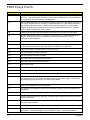
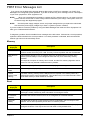
POST Error Messages List
If you cannot run the diagnostics program tests but did receive a POST error message, use "POST Error
Messages List" to diagnose system problems. If you did not receive any error message, look for a description
of your error symptoms in "Error Symptoms List"
NOTE:
When you have deemed it necessary to replace an FRU, and have done so, you must run a total
system check to ensure that no other activity has been affected by the change. This system check can
be done through the diagnostics program.
NOTE:
Check all power supply voltages, switch, and jumper settings before you replace the main board.
Also check the power supply voltages if you have a "system no-power" condition.
If you are unable to correct the problem by using the "BIOS Messages List" table and "Error Symptoms List"
table, go to "Undetermined Problems".
To diagnose a problem, first find the BIOS error messages in the left column. If directed to a check procedure,
replace the FRU indicated in the check procedure. If no check procedure is indicated, the first Action/FRU
listed in right column is the most likely cause.
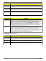
Memory
Message
Displayed
Description
Gate20 Error
The BIOS is unable to properly control the motherboard??s Gate A20 function, which
controls access of memory over 1 MB. This may indicate a problem with the motherboard.
Multi-Bit ECC
Error
This message will only occur on systems using ECC enabled memory modules. ECC
memory has the ability to correct single-bit errors that may occur from faulty memory
modules
A multiple bit corruption of memory has occurred, and the ECC memory algorithm cannot
correct it. This may indicate a defective memory module.
Parity Error
Fatal Memory Parity Error. System halts after displaying this message.
RAM R/W test
failed
This message is displayed by the AMIBIOS8 when the RAM read/write test fails.
CMOS
Memory Size
Wrong
The base memory (memory below 1MB) size that is reported in the CMOS (offset 15h)
mismatches with the actual size detected. This condition may occur when the hole is set at
512K base memory or when CMOS is corrupted.
Boot
Message
Displayed
Description
Boot Failure ...
This is a generic message indicating the BIOS could not boot from a particular device. This
message is usually followed by other information concerning the device.
Invalid Boot
Diskette
A diskette was found in the drive, but it is not configured as a bootable diskette.
Drive Not
Ready
The BIOS was unable to access the drive because it indicated it was not ready for data
transfer. This is often reported by drives when no media is present.
A: Drive Error
The BIOS attempted to configure the A: drive during POST, but was unable to properly
configure the device. This may be due to a bad cable or faulty diskette drive.
Chapter 4
47
Message
Displayed
Description
B: Drive Error
The BIOS attempted to configure the B: drive during POST, but was unable to properly
configure the device. This may be due to a bad cable or faulty diskette drive.
Insert BOOT
diskette in A:
The BIOS attempted to boot from the A: drive, but could not find a proper boot diskette.
Reboot and
Select proper
Boot device or
Insert Boot
Media in
selected Boot
device
BIOS could not find a bootable device in the system and/or removable media drive does
not contain media.
NO ROM
BASIC
This message occurs on some systems when no bootable device can be detected.
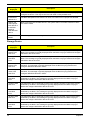
Storage Device
Message
Displayed
Description
Primary
Master Hard
Disk Error
The IDE/ATAPI device configured as Primary Master could not be properly initialized by the
BIOS. This message is typically displayed when the BIOS is trying to detect and configure
IDE/ATAPI devices in POST.
Primary Slave
Hard Disk
Error
The IDE/ATAPI device configured as Primary Slave could not be properly initialized by the
BIOS. This message is typically displayed when the BIOS is trying to detect and configure
IDE/ATAPI devices in POST.
Secondary
Master Hard
Disk Error
The IDE/ATAPI device configured as Secondary Master could not be properly initialized by
the BIOS. This message is typically displayed when the BIOS is trying to detect and
configure IDE/ATAPI devices in POST.
Secondary
Slave Hard
Disk Error
The IDE/ATAPI device configured as Secondary Slave could not be properly initialized by
the BIOS. This message is typically displayed when the BIOS is trying to detect and
configure IDE/ATAPI devices in POST.
3rd Master
Hard Disk
Error
The IDE/ATAPI device configured as Master in the 3rd IDE controller could not be properly
initialized by the BIOS. This message is typically displayed when the BIOS is trying to
detect and configure IDE/ATAPI devices in POST.
3rd Slave Hard
Disk Error
The IDE/ATAPI device configured as Slave in the 3rd IDE controller could not be properly
initialized by the BIOS. This message is typically displayed when the BIOS is trying to
detect and configure IDE/ATAPI devices in POST.
4th Master
Hard Disk
Error
The IDE/ATAPI device configured as Master in the 4th IDE controller could not be properly
initialized by the BIOS. This message is typically displayed when the BIOS is trying to
detect and configure IDE/ATAPI devices in POST.
4th Slave Hard
Disk Error
The IDE/ATAPI device configured as Slave in the 4th IDE controller could not be properly
initialized by the BIOS. This message is typically displayed when the BIOS is trying to
detect and configure IDE/ATAPI devices in POST.
5th Master
Hard Disk
Error
The IDE/ATAPI device configured as Master in the 5th IDE controller could not be properly
initialized by the BIOS. This message is typically displayed when the BIOS is trying to
detect and configure IDE/ATAPI devices in POST.
48
Chapter 4
Message
Displayed
Description
5th Slave Hard
Disk Error
The IDE/ATAPI device configured as Slave in the 5th IDE controller could not be properly
initialized by the BIOS. This message is typically displayed when the BIOS is trying to
detect and configure IDE/ATAPI devices in POST.
6th Master
Hard Disk
Error
The IDE/ATAPI device configured as Master in the 6th IDE controller could not be properly
initialized by the BIOS. This message is typically displayed when the BIOS is trying to
detect and configure IDE/ATAPI devices in POST.
6th Slave Hard
Disk Error
The IDE/ATAPI device configured as Slave in the 6th IDE controller could not be properly
initialized by the BIOS. This message is typically displayed when the BIOS is trying to
detect and configure IDE/ATAPI devices in POST.
Primary
Master Drive ATAPI
Incompatible
The IDE/ATAPI device configured as Primary Master failed an ATAPI compatibility test.
This message is typically displayed when the BIOS is trying to detect and configure IDE/
ATAPI devices in POST.
Primary Slave
Drive - ATAPI
Incompatible
The IDE/ATAPI device configured as Primary Slave failed an ATAPI compatibility test. This
message is typically displayed when the BIOS is trying to detect and configure IDE/ATAPI
devices in POST.
Secondary
Master Drive ATAPI
Incompatible
The IDE/ATAPI device configured as Secondary Master failed an ATAPI compatibility test.
This message is typically displayed when the BIOS is trying to detect and configure IDE/
ATAPI devices in POST.
Secondary
Slave Drive ATAPI
Incompatible
The IDE/ATAPI device configured as Secondary Slave failed an ATAPI compatibility test.
This message is typically displayed when the BIOS is trying to detect and configure IDE/
ATAPI devices in POST.
3rd Master
Drive - ATAPI
Incompatible
The IDE/ATAPI device configured as Master in the 3rd IDE controller failed an ATAPI
compatibility test. This message is typically displayed when the BIOS is trying to detect and
configure IDE/ATAPI devices in POST.
3rd Slave
Drive - ATAPI
Incompatible
The IDE/ATAPI device configured as Slave in the 3rd IDE controller failed an ATAPI
compatibility test. This message is typically displayed when the BIOS is trying to detect and
configure IDE/ATAPI devices in POST.
4th Master
Drive - ATAPI
Incompatible
The IDE/ATAPI device configured as Master in the 4th IDE controller failed an ATAPI
compatibility test. This message is typically displayed when the BIOS is trying to detect and
configure IDE/ATAPI devices in POST.
4th Slave Drive
- ATAPI
Incompatible
The IDE/ATAPI device configured as Slave in the 4th IDE controller failed an ATAPI
compatibility test. This message is typically displayed when the BIOS is trying to detect and
configure IDE/ATAPI devices in POST.
5th Master
Drive - ATAPI
Incompatible
The IDE/ATAPI device configured as Master in the 5th IDE controller failed an ATAPI
compatibility test. This message is typically displayed when the BIOS is trying to detect and
configure IDE/ATAPI devices in POST.
5th Slave Drive
- ATAPI
Incompatible
The IDE/ATAPI device configured as Slave in the 5th IDE controller failed an ATAPI
compatibility test. This message is typically displayed when the BIOS is trying to detect and
configure IDE/ATAPI devices in POST.
6th Master
Drive - ATAPI
Incompatible
The IDE/ATAPI device configured as Master in the 6th IDE controller failed an ATAPI
compatibility test. This message is typically displayed when the BIOS is trying to detect and
configure IDE/ATAPI devices in POST.
Chapter 4
49
Message
Displayed
Description
6th Slave Drive
- ATAPI
Incompatible
The IDE/ATAPI device configured as Slave in the 6th IDE controller failed an ATAPI
compatibility test. This message is typically displayed when the BIOS is trying to detect and
configure IDE/ATAPI devices in POST.
S.M.A.R.T.
Capable but
Command
Failed
The BIOS tried to send a S.M.A.R.T. message to a hard disk, but the command transaction
failed.
This message can be reported by an ATAPI device using the S.M.A.R.T. error reporting
standard. S.M.A.R.T. failure messages may indicate the need to replace the hard disk.
S.M.A.R.T.
Command
Failed
The BIOS tried to send a S.M.A.R.T. message to a hard disk, but the command transaction
failed.
This message can be reported by an ATAPI device using the S.M.A.R.T. error reporting
standard. S.M.A.R.T. failure messages may indicate the need to replace the hard disk.
S.M.A.R.T.
Status BAD,
Backup and
Replace
A S.M.A.R.T. capable hard disk sends this message when it detects an imminent failure.
This message can be reported by an ATAPI device using the S.M.A.R.T. error reporting
standard. S.M.A.R.T. failure messages may indicate the need to replace the hard disk.
S.M.A.R.T.
Capable and
Status BAD
A S.M.A.R.T. capable hard disk sends this message when it detects an imminent failure.
This message can be reported by an ATAPI device using the S.M.A.R.T. error reporting
standard. S.M.A.R.T. failure messages may indicate the need to replace the hard disk.
Virus Related
Message
Displayed
Description
BootSector
Write
The BIOS has detected software attempting to write to a drive??s boot sector. This is
flagged as possible virus activity. This message will only be displayed if Virus Detection is
enabled in AMIBIOS setup.
VIRUS:
Continue (Y/N)
If the BIOS detects possible virus activity, it will prompt the user. This message will only be
displayed if Virus Detection is enabled in AMIBIOS setup.
System Configuration
Message
Displayed
DMA-1 Error
Description
Error initializing primary DMA controller. This is a fatal error, often indication a problem with
system hardware
DMA-2 Error
Error initializing secondary DMA controller. This is a fatal error, often indication a problem
with system hardware.
DMA
Controller
Error
POST error while trying to initialize the DMA controller. This is a fatal error, often indication
a problem with system hardware.
Checking
NVRAM..Upda
te Failed
BIOS could not write to the NVRAM block. This message appears when the FLASH part is
write-protected or if there is no FLASH part (System uses a PROM or EPROM).
50
Chapter 4
Message
Displayed
Description
Microcode
Error
BIOS could not find or load the CPU Microcode Update to the CPU. This message only
applies to INTEL CPUs. The message is most likely to appear when a brand new CPU is
installed in a motherboard with an outdated BIOS. In this case, the BIOS must be updated
to include the Microcode Update for the new CPU.
NVRAM
Checksum
Bad, NVRAM
Cleared
There was an error in while validating the NVRAM data. This causes POST to clear the
NVRAM data.
Resource
Conflict
More than one system device is trying to use the same non-shareable resources (Memory
or I/O).
NVRAM
Ignored
The NVRAM data used to store Plug??n??Play (PnP) data was not used for system
configuration in POST.
NVRAM Bad
The NVRAM data used to store Plug??n??Play (PnP) data was not used for system
configuration in POST due to a data error.
Static
Resource
Conflict
Two or more Static Devices are trying to use the same resource space (usually Memory or
I/O).
PCI I/O conflict
A PCI adapter generated an I/O resource conflict when configured by BIOS POST.
PCI ROM
conflict
A PCI adapter generated an I/O resource conflict when configured by BIOS POST.
PCI IRQ
conflict
A PCI adapter generated an I/O resource conflict when configured by BIOS POST.
PCI IRQ
routing table
error
BIOS POST (DIM code) found a PCI device in the system but was unable to figure out how
to route an IRQ to the device. Usually this error is causing by an incomplete description of
the PCI Interrupt Routing of the system.
Timer Error
Indicates an error while programming the count register of channel 2 of the 8254 timer.
This may indicate a problem with system hardware.
Refresh timer
test failed
BIOS POST found that the refresh timer hardware failed to pass the Refresh Retrace Test.
Interrupt
Controller-1
error
BIOS POST could not initialize the Master Interrupt Controller. This may indicate a problem
with system hardware.
Interrupt
Controller-2
error
BIOS POST could not initialize the Slave Interrupt Controller. This may indicate a problem
with system hardware.
CMOS
Message
Displayed
Description
CMOS Date/
Time Not Set
The CMOS Date and/or Time are invalid. This error can be resolved by readjusting the
system time in AMIBIOS Setup.
CMOS Battery
Low
CMOS Battery is low. This message usually indicates that the CMOS battery needs to be
replaced. It could also appear when the user intentionally discharges the CMOS battery.
Chapter 4
51
Message
Displayed
Description
CMOS
Settings
Wrong
CMOS settings are invalid. This error can be resolved by using AMIBIOS Setup.
CMOS
Checksum
Bad
CMOS contents failed the Checksum check. Indicates that the CMOS data has been
changed by a program other than the BIOS or that the CMOS is not retaining its data due to
malfunction. This error can typically be resolved by using AMIBIOS Setup.
Miscellaneous
Message
Displayed
Description
KBC BAT Test
failed
Keyboard controller BAT test failed. This may indicate a problem with keyboard controller
initialization.
Keyboard
Error
Keyboard is not present or the hardware is not responding when the keyboard controller is
initialized.
PS2 Keyboard
not found
PS2 Keyboard support is enabled in the BIOS setup but the device is not detected.
PS2 Mouse
not found
PS2 Mouse support is enabled in the BIOS setup but the device is not detected.
Keyboard/
Interface Error
Keyboard Controller failure. This may indicate a problem with system hardware.
Unlock
Keyboard
PS2 keyboard is locked. User needs to unlock the keyboard to continue the BIOS POST.
System Halted
The system has been halted. A reset or power cycle is required to reboot the machine. This
message appears after a fatal error has been detected.
<INS>
Pressed
Indicates that <INS> key is pressed during the BIOS POST. The POST will load and use
default CMOS settings.
Password
check failed
The password entered does not match the password set in the setup. This condition may
occur for both Supervisor and User password verification.
Unknown
BIOS error.
Error code =
004Ah
This message is displayed when ADM module is not present in the AMIBIOS8 ROM.
Unknown
BIOS error.
Error code =
004Bh
This message is displayed when language module is not present in the AMIBIOS8 ROM.
Floppy
Controller
Failure
Error in initializing legacy Floppy Controller.
52
Chapter 4
USB eModule Error Messages
Message Displayed
Description
Warning! Unsupported USB device
found and disabled!
This message is displayed when a non-bootable USB device is
enumerated and disabled by the BIOS.
Warning! Port 60h/64h emulation is
not supported by this USB Host
Controller!
This message is displayed to indicate that port 60h/64h emulation
mode cannot be enabled for this USB host controller. This condition
occurs if USB KBC emulation option is set for non-SMI mode.
Warning! EHCI controller disabled.
It requires 64bit data support in the
BIOS.
This message is displayed to indicate that EHCI controller is disabled
because of incorrect data structure. This condition occur if the USB
host controller needs 64-bit data structure while the USB is ported
with 32-bit data structure.
SMBIOS eModule Error Messages
Message Displayed
Not enough space in Runtime area!!. SMBIOS data
will not be available.
Description
This message is displayed when the size of the
SMBIOS data exceeds the available SMBIOS
runtime storage size
CPU eModule Error Messages
Message Displayed
Warning! This system board does not support the
power requirements of the installed processor. The
processor will be run at a reduced frequency, which
will impact system performance. area!!. SMBIOS
data will not be available.
Description
This message is displayed when the power
requirements of the board do not match the power
requirement of the CPU.
MPS Table (Multi-processor) eModule Error Messages
Message Displayed
Insufficient Runtime space for MPS data! System
may operate in PIC or Non-MPS mode.
Chapter 4
Description
This message is displayed when there is not enough
space in the 0F000h runtime area for creating MPS
table.
53
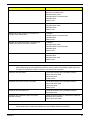
Error Symptoms List
NOTE: To diagnose a problem, first find the error symptom in the left column. If directed to a check procedure,
replace the FRU indicated in the check procedure. If no check procedure is indicated, the first Action/
FRU listed in right column is the most likely cause.
Error Symptom
Action/FRU
Processor / Processor Fan
NOTE: Normally, the processor fan should be operative, and the processor clock setting should be
exactly set to match its speed requirement before diagnosing any processor problems.
Processor fan does not run but power supply fan
runs.
1. Ensure the system is not in power saving
mode.See “Power Management”in chapter2.
2.With the system power on, measure the voltage of
processor fan connector. Its reading should be
+12Vdc. Its reading should be +12Vdc. If the reading
shows normal, but the fan still does not work, then
replace a good fan.3. Main board.
Processor test failed.
1.Processor.
2.Main board.
Main board and Memory
NOTE: Ensure the memory modules are installed properly and the contact leads are clean before
diagnosing any system problems.
Memory test failed.
1.See "Memory"
2.Main board
Incorrect memory size shown or repeated during
POST.
1.Insert the memory modules in the DIMM sockets
properly, then reboot the system.
2.Memory module.
3.Main board.
System works but fails to enter power saving mode
when the Power Management Mode is set to
Enabled.
1.Enter BIOS Setup and load default settings.In
Windows Systems, check settings in Power
Management Property of Control Panel.
2.Reload software from Recovery CD.
Blinking cursor only; system does not work.
1.Diskette/IDE drive connection/cables
2. Diskette/IDE disk drives
3.See “Undetermined Problems”.
4.Main board
Diskette Drive
NOTE: Ensure the diskette drive is auto-setting in BIOS Setup and its read/write head is clean before
diagnosing any diskette drive problems.(If only one drive is installed, please make sure the drive is
connected to master connector or the drive is set to master.)
Media and drive are mismatched.
54
1.Ensure the diskette drive is configured correctly in
the Disk Drives of BIOS Setup.
2.Ensure the diskette drive is correctly formatted.
3.Diskette drive connection/cable
4.Diskette drive
5.Main board
Chapter 4
Error Symptom
Action/FRU
Diskette drive does not work.
1.Ensure the diskette drive is not set to None in the
Disk Drives of BIOS Setup.
2.Diskette drive power
3.Diskette drive connection/cable
4.Diskette drive
5.Main board
Diskette drive read/write error.
1.Diskette.
2.Diskette drive cable.
3.Diskette drive.
4.Main board
Diskette drive LED comes on for more than 2
minutes when reading data.
1.Diskette
2.Diskette drive connection/cable
3.Diskette drive
4.Main board
Diskette drive LED fails to light, and the drive is
unable to access for more than 2 minutes.
1.Diskette
2.Diskette drive power
3.Diskette drive connection/cable
4.Diskette drive
5.Main board
Diskette drive test failed.
1.Diskette
2.Diskette drive
3.Diskette drive cable
4.Main board
Hard Disk Drive
NOTE: Ensure hard disk drive is configured correctly in BIOS Setup, cable/jumper are set correctly
before diagnosing any hard disk drive problems. (If only one drive is installed, please make sure
the drive is connected to master connector or the drive is set to master.)
Hard disk drive test failed.
1.Enter BIOS Setup and Load default settings.
2.Hard disk drive cable.
3.Hard disk drive.
4. Main board.
Hard disk drive cannot format completely.
1.Enter BIOS Setup and Load default settings.
2.Hard disk drive cable.
3.Hard disk drive.
4.Main board
Hard disk drive has write error.
1.Enter BIOS Setup and Load default settings.
2.Hard disk drive.
Hard disk drive LED fails to light, but system
operates normally.
1.With the system power on, measure the voltage of
hard disk LED connector.
2.Hard drive LED cable.
CD/DVD-ROM Drive
NOTE: Ensure CD/DVD-ROM drive is configured correctly in BIOS Setup, cable/jumper are set correctly
and its laser beam is clean before diagnosing any CD/DVD-ROM drive problems.
Chapter 4
55
Error Symptom
Action/FRU
CD/DVD-ROM drive LED doesn't come on but works
normally.
1.CD/DVD-ROM drive
CD/DVD-ROM drive LED flashes for more than 30
seconds before LED shutting off.
Software asks to reinstall disc.Software displays a
reading CD/DVD error.
1.CD/DVD-ROM may have dirt or foreign material on
it. Check with a known good disc.
2. CD/DVD-ROM is not inserted properly.
3.CD/DVD-ROM is damaged.
CD/DVD-ROM drive cannot load or eject when the
system is turned on and its eject button is pressed
and held.
1.Disconnect all cables from CD/DVD-ROM drive
except power cable, then press eject button to try to
unload the disk.
2.CD/DVD-ROM drive power.
3.CD/DVD-ROM drive
CD/DVD-ROM drive does not read and there are no
messages are displayed.
1.CD may have dirt or foreign material on it. Check
with a known good disc.
2.Ensure the CD/DVD-ROM driver is installed
properly.
3.CD/DVD-ROM drive.
CD/DVD-ROM drive can play audio CD but no
sound output.
1.Ensure the headphone jack of the CD/DVD-ROM
has an output.
2.Turn up the sound volume.
3.Speaker power/connection/cable.
4.CD/DVD-ROM drive.
Real-time clock
Real-time clock is inaccurate.
1.Ensure the information in the Standard CMOS
Feature of BIOS Setup is set correctly.
2.RTC battery.
3.Main board.
Audio
Audio software program invokes but no sound
comes from speakers.
1.Speaker power/connection/cable.
Modem
Modem ring cannot wake up system from suspend
mode.
1.For the External Modem, make sure Power on By
Ring in BIOS Setup or Power Management is set to
Enabled. For the PCI modem, make sure Wake up
by PCI card is set to Enabled.
2.If PCI modem card is used, reinsert the modem
card to PCI slot firmly or replace the modem card.
3.In Win 98, ensure the telephone application is
configured correctly for your modem and set to
receive messages and/or fax.
Data/fax modem software program invokes but
cannot receive/send data/fax
1.Ensure the modem card is installed properly.
Fax/voice modem software program invokes but has
no sound output. (Data files are received normally;
voice from modem cannot be produced, but system
sound feature works normally.)
1.Ensure the modem voice-in cable from modem
adapter card to main board
Video and Monitor
56
Chapter 4
Error Symptom
Action/FRU
Video memory test failed.Video adapter failed.
1.Remove all non-factory-installed cards.
2.Load default settings (if screen is readable).
3.Main board
Display problem:
Incorrect colors
No high intensity
Missing, broken, or incorrect characters
Blank monitor (dark)
Blank monitor (bright)
Distorted image
Unreadable monitor
1.Monitor signal connection/cable.
2.Monitor
3.Video adapter card
4.Main board
Other monitor problems
Display changing colors.
1.Monitor signal connection/cable
2.Monitor
3.Main board
Display problem not listed above (including blank or
illegible monitor).
1.”Monitor"
2.Load default settings (if screen is readable).
3.Main board
Parallel/Serial Ports
Execute “Load BIOS Default Settings” in BIOS Setup to confirm ports presence before diagnosing any
parallel/serial ports problems.
Serial or parallel port loop-back test failed.
1.Make sure that the LPT# or COM# you test is the
same as the setting in BIOS Setup.
2.Loop-back.
3.Main board
Printing failed.
1.Ensure the printer driver is properly installed.
Refer to the printer service manual.
2.Printer.
3.Printer cable.
4.Main board.
Printer problems.
1.Refer to the service manual for the printer.
Keyboard
Some or all keys on keyboard do not work.
1.Keyboard
Power Supply
Pressing power switch does not turn off system.
(Only unplugging the power cord from electrical
outlet can turn off the system.)
1.Ensure the Soft-off by PWR-BTTN. in BIOS Setup
of Power Management is not set to Instant-off.
2.Power switch cable assembly
Pressing power switch does not turn on the system.
1.Ensure the power override switch (situated at the
back of the machine, just above the connector for
the power cable) is not set to OFF.
2.Power switch cable assembly.
Chapter 4
57
Error Symptom
Action/FRU
Executing software shutdown from Windows98 Start
menu does not turn off the system. (Only pressing
power switch can turn off the system).
1.Load default settings.
2.Reload software from Recovery CD.
No system power, or power supply fan is not
running.
1.Power Supply
2.Main board
Other Problems
Any other problems.
58
1.Undetermined Problems
Chapter 4
Undetermined Problems
If an error message is present, go to "POST Error Messages List" on page 85. If you did not receive any
messages, if the symptom is listed in "or "Error Symptoms List" on page 87. If you still cannot solve the
problem, continue with this check:
1.
Check the power supply voltage. If the voltage are correct continue with the following steps:
2.
Power off the system unit.
3.
Perform the following checks, one by one, until you have isolated the problem FRU.
4.
Load default settings in setup.
5.
Check all main board jumper positions and switch settings.
6.
Check all adapter card jumper positions.
7.
Check all device jumper positions.
8.
Check all cables and connectors for proper installation.
9.
If the jumpers, switches and voltage settings are correct, remove or disconnect the following, one at a
time:
10. Non-Acer devices
•
External devices
•
Any adapter card (modem card, LAN card or video card, if installed)
•
CD/DVD-ROM drive
•
Diskette drive
•
Hard disk drive
•
DIMM
•
Processor
•
Main board
11. Power on the system unit.
12. Repeat steps 2 through 5 until you find the failing device or adapter.
Chapter 4
59
Chapter 5
Jumper and Connector Information
M/B Placement
Chapter 5
61
No
Label
Description
No
Label
Description
1
CPU Socket
CONN,Socket,IntelPrescot
tCPU,LGA775P,10u,G,SMD
11
1394A1
Onboard 1394a header
2
CPU_FAN
CPU fan power header
12
SPDIF_OUT1
~2
SPDIF out header
3
DIMM1~4
CONN,DIMM,DDRIII,1.5V,
V/T,Blu,15u,G,DIP-240
13
F_AUDIO
Front panel audio header
4
GPIO1~2
General Purpose Input/
Output headers
14
PCI1~2
32-bit add-on card slots
5
ATX_POWER
1
M/B main power connector
15
SPI_ROM
SPI_ROM header
6
ME_DISABLE
Front panel USB header
16
PCIEx1-1
PCIEx 1 socket
7
SATA1~6
SATA data transfe
connectors
17
PCIE1
PCIEx 16 socket
8
F_PANEL
Front panel audio header
18
ATX12V1
4-pin +12V power
connector
9
F_USB1~4
Front panel USB headers
19
SYS_FAN
System cooling fan
connector
10
CLR_CMOS
Clear CMOS jumper
62
Chapter 5
Jumper Setting
The section explains how to set jumper for correct configuration of the mainboard.
Setting Jumper
Use the motherboard jumpers to set system configuration options. Jumpers with more Than one pin are
numbered. When setting the jumpers, ensure that the jumper caps are Placed on the correct pins.
Internal header pin definition
Jumper/Header Name
Chapter 5
Function
Definition
CLEAR CMOS HEADER
1-2: NORMAL (Default)
2-3: CLEAR CMOS
ME_DISABLE HEADER
1-2:NORMAL
2-3:MEDISABLE(Default)
GPIO HEADER
(RESERVE)
1:G941
2: GND
GPIO HEADER
(RESERVE)
1:GP46
2: GND
CPU FAN HEADER
1: GND
2: +12V
3: SENSE
4: PWM CONTROL
63
Jumper/Header Name
Function
SYS FAN HEADER
(3pin & 4 pin colay
default:3 pin)
1: GND
2: +12V
3: SENSE
4: PWM CONTROL(4 pin
Fan)
FRONT PANEL HEADER
1: SATALED+
2: ACPI_LED
3: SATALED4: PWR_LED
5: GND
6: PWR_SW
7: RESET
8: GND
9: NC
10: Key
11: NC
12: VCC
13: NC
14: -ACTIVE_C
FRONT USB HEADER
1: USBVCC_1
2: USBVCC_1
3: USB0_XN
4: USB1_XN
5: USB0_XP
6: USB1_XP
7:GND
8: GND
9: KEY
10: GND
F_USB1
1
3
5
7
9
VCC
VCC
USB0-
USB1-
USB0+
USB1+
GND
GND
KEY
OC0
2
4
6
8
10
H5X2-P9E-Y
F_USB2
1
3
5
7
9
VCC
VCC
USB0-
USB1-
USB0+
USB1+
GND
GND
KEY
OC0
H5X2-P9E-Y
64
2
4
6
8
10
Definition
FRONT USB HEADER
1: USBVCC_2
2: USBVCC_2
3: USB2_XN
4: USB4_XN
5: USB2_XP
6: USB4_XP
7:GND
8: GND
9: KEY
10: GND
Chapter 5
Jumper/Header Name
Function
F_USB3
1
3
5
7
9
VCC
VCC
USB0-
USB1-
USB0+
USB1+
GND
GND
KEY
OC0
2
4
6
FRONT USB HEADER
8
10
H5X2-P9E-Y -O
Chapter 5
Definition
1: USBVCC_3
2: USBVCC_3
3: USB5_XN
4: USB7_XN
5: USB5_XP
6: USB7_XP
7:GND
8: GND
9: KEY
10: GND
FRONT USB HEADER
1: USBVCC_4
2: USBVCC_4
3: USB3_XN
4: USB6_XN
5: USB3_XP
6: USB6_XP
7:GND
8: GND
9: KEY
10: GND
FRONT AUDIO HEADER
1: PORT-F_L
2: AUGND
3: PORT-F_R
4: FRONT_AUD_DET
5: PORT-E_R
6: MIC2_JD
7: AUGND
8: KEY
9: PORT-E_L
10: LINE2_JD
SPDIF HEADER
1: VCC
2: KEY
3: SPO1
4: GND
SPDIF HEADER
1: VCC
2: KEY
3: SPO2
4: GND
65
Jumper/Header Name
Function
FRONT 1394 HEADER
Definition
1: T_PA0+
2: T_PA03: GND
4: GND
5: T_PB0+
6: T_PB07: CPWR1
8: CPWR1
9: KEY
10: GND
Connector pin definition
Connector Name
66
Function
Definition
PSKBMS CONN
1: KBDATA
2: NC
3: GND
4: KBVCCSB
5: KBCLK
6: NC
7: MSDATA
8: NC
9: GND
10: KBVCCSB
11: MSCLK
12: NC
13: GND
14: GND
15: GND
16: GND
17: GND
HDMI CONN
1: HDMI_TX2_P
3: HDMI_TX2_N
4: HDMI_TX1_P
6: HDMI_TX1_N
7: HDMI_TX0_P
9: HDMI_TX0_N
10: HDMI_TXC_P
12: HDMI_TXC_N
13,14: NC
15: SLHD_CLK
16: SLHD_DATA
18: HDMIVCC
19: HD_HPD
2,5,8,11,17,20,21,22,23:
GND
Chapter 5
Connector Name
Chapter 5
Function
Definition
VGA CONN
1: RED
2: GREEN
3: BLUE
4,11: NC
9: HDMIVCC
12: VDAC_SDAT
13: HSYNC
14: VSYNC
15: VDAC_SCLK
5,6,7,8,10,16,17: GND
USB+1394 CONN
1: USBVCC_5
2: USB9_XN
3: USB9_XP
4: AUGND2
5: USBVCC_5
6: USB8_XN
7: USB8_XP
8: AUGND2
9: CPWR2
10: AUGND2
11: T_PB112: T_PB1+
13: T_PA114: T_PA1+
15: USBVDD1
G1,G2,G3,G4,G5,G6,G7,
G8: AUGND2
67
Connector Name
68
Function
Definition
USB+LAN CONN
1:USBVCC_6 12:MDI1_P
2:USB10_XN 13:MDI1_N
3:USB10_XP 14:MDI2_P
4:AUGND2
15:MDI2_N
5:USBVCC_6 16:MDI3_P
6:USB11_XN 17:MDI3_N
7:USB11_XP
18:DGND
8:AUGND2
9:LAN_1P8V
10: MDI0_P
11: MDI0_N
19:LAN_LED2
20:LAN_LED1
21: LAN_LED0
22: CL_3P3V
G1,G2,G3,G4,G5,G6,G7,
G8: AUGND2
SATA CONN
1: GND
2: SATA0_TX_P
3: SATA0_TX_N
4: GND
5: SATA0_RX_N
6: SATA0_RX_P
7: GND
SATA CONN
1: GND
2: SATA1_TX_P
3: SATA1_TX_N
4: GND
5: SATA1_RX_N
6: SATA1_RX_P
7: GND
Chapter 5
Connector Name
Chapter 5
Function
Definition
SATA CONN
1: GND
2: SATA2_TX_P
3: SATA2_TX_N
4: GND
5: SATA2_RX_N
6: SATA2_RX_P
7: GND
SATA CONN
1: GND
2: SATA3_TX_P
3: SATA3_TX_N
4: GND
5: SATA3_RX_N
6: SATA3_RX_P
7: GND
SATA CONN
1: GND
2: SATA4_TX_P
3: SATA4_TX_N
4: GND
5: SATA4_RX_N
6: SATA4_RX_P
7: GND
SATA CONN
1: GND
2: SATA5_TX_P
3: SATA5_TX_N
4: GND
5: SATA5_RX_N
6: SATA5_RX_P
7: GND
69
Connector Name
70
Function
Definition
ATX_POWER CONN
1:VCC3
13:VCC3
2:VCC3
14:-12V
3: GND
15:GND
4:VCC 16:ATX_PSON_L
5:GND
17:GND
6:VCC
18:GND
7:GND
19:GND
8:ATX_PWRGD 20:NC
9:5VSB
21VCC
10:+12V
22:VCC
11:+12V
23:VCC
12:VCC3
24:GND
ATX12V CONN
1: GND
2: GND
3: +12V_4P
4: +12V_4P
Chapter 5
Chapter 6
FRU (Field Replaceable Unit) List
This chapter offers the FRU (Field Replaceable Unit) list in global configuration of the Aspire M3802 desktop
computer. Refer to this chapter whenever ordering the parts to repair or for RMA (Return Merchandise
Authorization).
NOTES:
chapter 6
•
When ordering FRU parts, check the most up-to-date information available on your regional web
or channel. For whatever reasons a part number is changed, it will NOT be noted on the printed
Service Guide. For Acer authorized service providers, your Acer office may have a different part
number code from those given in the FRU list of this printed Service Guide. You MUST use the
local FRU list provided by your regional Acer office to order FRU parts for service.
•
To scrap or to return the defective parts, follow the local government ordinance or regulations on
how to dispose it properly, or follow the rules set by your regional Acer office on how to return it.
•
This document will be updated as more information about the FRU list becomes available.
71
Aspire M3802 Exploded Diagram
NOTE: This section will be updated when more information becomes available.
72
Chapter 6
NO.
Description
NO.
Description
1
6IN5-WITH-1394-X1-ASH-1
15
MB-SUPPORT
2
CDROM-NEC-4DX
16
M330-SUB-CHASSIS
3
ACER-M330-MAIN-CHASSIS
17
POWER-PCBA
4
HOD-BKT
18
M330-LIGHT
5
M330-SIDE-DOOR
19
LIGHT-COSTIC
6
CHASSIS-SUPPORT
20
POWER-BOTTON
7
ATX-POWER-AA
21
ODD-BUTTON
8
PCI-DOOR
22
COSMETIC-LOOP-BOTTON
9
REAR-CHASSIS
23
ODD-COVER
10
ODD-CAGE
24
LENS-NEW
11
TOP-BEZEL
25
CHAGE-COVER
12
TOP-RORATE-DOOR
26
LED-3
13
USB-ASM-NEW
27
M330-SPRING-ODD-BUTTON
14
M330-TOP-COVER-METAL
28
A3-ASPRIRE-ODD-DOOR-SPRING
Chapter 6
73
Aspire M3802 FRU List
Category
Description
Part Number
MAINBOARD
MB Kit HimalayanII_D2 Intel G43 ICH10R GMA X4500 384M Intel 82567V
Giga LAN ATX W/ 1394 V1.0 LF w/ EuP Lot6
MB.SCQ07.002
IOI 16-in-1 CR M1/M3 w/3.5", USB2.0, UsBSET UT330-LK w/micro SD, M2
CR.10400.071
KYE 16-in-1 CR M1/M3 w/3.5", USB2.0, Realtek RTS-5181 w/micro SD, M2
CR.10400.072
FAN COOLER P4_SKT775 PKP367 W/I SUNON 4000RPM
HI.3670C.001
Fan Cooler LGA775 TMD06 Fan 9225
HI.10800.006
Non-PFC 250W (30L) EuP
PY.25009.006
Non-PFC 250W (30L) EuP
PY.25008.031
PFC 250W (30L) EuP
PY.25009.005
PFC 250W (30L) EuP
PY.25008.032
Non-PFC 300W (30L) EuP
PY.3000B.015
Non-PFC 300W (30L) EuP
PY.30008.028
FR 300W (30L) EuP 82+
PY.30009.019
FR 300W (30L) EuP 82+
PY.30008.029
Core 2 Quad Q9650 (3.0G 12M 1333FSB), 95W , E0
KC.96501.QQE
Core 2 Quad Q9550 (2.83G 12M 1333FSB), 95W , E0
KC.95501.QQE
Core 2 Quad Q9400 (2.66G 6M 1333FSB) , 95W , R0
KC.94001.QQ0
Core 2 Duo E8600 (3.33G 6M 1333FSB) , 65W , E0
KC.86001.DEE
Core 2 Quad Q8400 (2.66G 4M 1333FSB) ,95W , R0
KC.84001.QQ0
Core 2 Quad Q8300 (2.5G 4M 1333FSB) 95W , R0
KC.83001.QQV
CARD READER
CPU COOLER
SYSTEM FAN
POWER
SUPPLY
CPU
74
Chapter 6
Category
Description
Part Number
Core 2 Quad Q8200 (2.33G 4M 1333FSB) 95W , M1
KC.82001.QQR
Core 2 Duo E8500 (3.16G 6M 1333FSB) , 65W , E0
KC.85001.DEE
Core 2 Duo E8400 (3.0G 6M 1333FSB) , 65W , E0
KC.84001.DEE
Core 2 Duo E7600 (2.66G 3M 1066FSB) , 65W , R0
KC.76001.DE0
Core 2 Duo E7500 (2.66G 3M 1066FSB) , 65W , R0
KC.75001.DEV
Core 2 Duo E7300 (2.66G 3M 1066FSB) , 65W , M0
KC.73001.DE0
Pentium Dual Core E6300 (2.8G 2M 1066FSB) , 65W , R-0
KC.63001.DEM
Pentium Dual Core E5400 (2.7G 2M 800FSB) , 65W , R-0
KC.54001.DEV
Pentium Dual Core E5300 (2.6G 2M 800FSB) , 65W , R-0
KC.53001.DEV
Pentium Dual Core E5200 (2.5G 2M 800FSB) , 65W , R-0
KC.52001.DER
Memory UNIFOSA UNB-DIMM DDRII 800 1GB GU341G0ALEPR6B2C6F1
LF 128*8 0.065um
KN.1GB0H.013
Memory NANYA UNB-DIMM DDRII 800 1GB NT1GT64U88D0BY-AD LF
128*8 0.07um
KN.1GB03.024
Memory SAMSUNG UNB-DIMM DDRII 800 1GB M3782863QZS-CF7 LF
128*8 0.065um
KN.1GB0B.021
Memory SAMSUNG UNB-DIMM DDRII 800 1GB M378T2863EHS-CF7 LF
128*8 0.055um
KN.1GB0B.034
Memory HYNIX UNB-DIMM DDRII 800 1GB HYMP112U64CP8-S6 LF 128*8
0.065um
KN.1GB0G.015
Memory UNIFOSA UNB-DIMM DDRII 800 2GB GU342G0ALEPR692C6F1
LF 128*8 0.065um
KN.2GB0H.007
Memory NANYA UNB-DIMM DDRII 800 2GB NT2GT64U8HD0BY-AD LF
128*8 0.07um
KN.2GB03.009
Memory HYNIX UNB-DIMM DDRII 800 2GB HYMP125U64CP8-S6 LF 128*8
0.065um
KN.2GB0G.008
Memory SAMSUNG UNB-DIMM DDRII 800 2GB M378T5663QZ3-CF7 LF
128*8 0.065um
KN.2GB0B.006
Memory SAMSUNG UNB-DIMM DDRII 800 2GB M378T5663EH3-CF7 LF
128*8 0.055um
KN.2GB0B.022
160GB
KH.16007.023
320GB
KH.32007.006
640GB
KH.64007.001
1TB
KH.01K07.002
160GB
KH.16001.041
320GB
KH.32001.015
750GB
KH.75001.008
1TB
KH.01K01.007
Memory
HDD
Chapter 6
75
Category
Description
Part Number
1.5TB
KH.15K01.002
640GB
KH.64008.003
750GB
KH.75008.005
1TB
KH.01K08.005
2TB
KH.02K08.001
DH-16D5S Win7
KV.0160F.002
DH-20N(H/F) Win7
KV.0160D.016
GH-41F(H/F) Win7 non-Labelflash
KU.0160D.049
DH-16AASH (H/F) Win7 non-Labelflash
KU.0160F.009
DH-4O3S Win7
KV.0040F.002
CH-10F Win7 non-Labelflash
KO.0060D.004
DH-6E2S Win7 non-Labelflash
KO.0060F.002
GEFORCE GT220 1GB DDR2 (128BITS) SAMSUNG DVI HDMI VGA ATX
BRACKET
VG.PCGT2.201
GEFORCE G210 512MB DDR2 (64BITS) SAMSUNG DVI HDMI VGA ATX
BRACKET
VG.PCG02.101
HD4650 1GB DDR 2 (128BITS) SAMSUNG DVI HDMI VGA W/ATX BKT
ROHS
VG.APC46.502
HD4350 512MB DDR 2 (64BITS) SAMSUNG DVI HDMI VGA W/ATX BKT
ROHS
VG.APC43.501
PE988-A TV Tuner Card PCIe Hybrid ATSC with S/W Encoder
TU.10500.038
PE988-D TV Tuner Card PCIe Hybrid DVB-T with S/W Encoder
TU.10500.040
Avermedia H751-A TV Tuner Card PCIe Hybrid ATSC, S/W Encoder
TU.10500.045
Avermedia H751-D TV Tuner Card PCIe Hybrid ATSC, S/W Encoder
TU.10500.048
D-1156I#/A7A, Modem PCI card, LSI Universal Modem (PCI) 56K V.92 Pinball (P40)
FX.10100.004
WP61R2, WLAN PCI Card 802.11 b/g, Realtek RTL8185L
NI.10200.005
WP81R1, WLAN PCI Card 802.11b/g/n 1T x 2R, Realtek RTL8190
NI.10200.021
WN5301A, WLAN PCI Card 802.11 b/g, Atheros AR2415
NI.10200.027
ODD
VGA CARD
TV TUNER
MODEM
WLAN CARD
76
Chapter 6
Category
Description
Part Number
MOUSE
Acer 0810 Project PS2 Optical mouse
MS.11200.013
Logitech 0810_USB Optical mouse USB M-UAY-ACR2
MS.11200.014
Lite-On PS2 optical mouse PS2 SM-9620
MS.11200.017
Lite-On USB optical USB SM-9625
MS.11200.018
Logitech USB Optical mouse USB M-UAE96 GS
MS.11200.019
Keyboard CHICONY KB-0759 PS/2 Standard 104KS Black US w/o eKey
KB.PS203.284
Keyboard CHICONY KB-0759 PS/2 Standard 104KS Black Traditional
Chinese w/o eKey
KB.PS203.285
Keyboard CHICONY KB-0759 PS/2 Standard 104KS Black Simplified
Chinese w/o eKey
KB.PS203.286
Keyboard CHICONY KB-0759 PS/2 Standard 104KS Black US International
w/o eKey
KB.PS203.287
Keyboard CHICONY KB-0759 PS/2 Standard 104KS Black Arabic/English w/
o eKey
KB.PS203.288
Keyboard CHICONY KB-0759 PS/2 Standard 104KS Black Thailand w/o
eKey
KB.PS203.289
Keyboard CHICONY KB-0759 PS/2 Standard 105KS Black Spanish w/o eKey
KB.PS203.290
Keyboard CHICONY KB-0759 PS/2 Standard 105KS Black Portuguese w/o
eKey
KB.PS203.291
Keyboard CHICONY KB-0759 PS/2 Standard 105KS Black Canadian French
w/o eKey
KB.PS203.292
Keyboard CHICONY KB-0759 PS/2 Standard 107KS Black Brazilian
Portuguese w/o eKey
KB.PS203.293
Keyboard CHICONY KB-0759 PS/2 Standard 109KS Black Japanese w/o
eKey
KB.PS203.294
Keyboard CHICONY KB-0759 PS/2 Standard 105KS Black German w/o eKey
KB.PS203.295
Keyboard CHICONY KB-0759 PS/2 Standard 105KS Black Italian w/o eKey
KB.PS203.296
Keyboard CHICONY KB-0759 PS/2 Standard 105KS Black French w/o eKey
KB.PS203.297
Keyboard CHICONY KB-0759 PS/2 Standard 105KS Black Swedish w/o
eKey
KB.PS203.298
Keyboard CHICONY KB-0759 PS/2 Standard 105KS Black UK w/o eKey
KB.PS203.299
Keyboard CHICONY KB-0759 PS/2 Standard 105KS Black Dutch w/o eKey
KB.PS203.300
Keyboard CHICONY KB-0759 PS/2 Standard 105KS Black Swiss/G w/o
eKey
KB.PS203.301
Keyboard CHICONY KB-0759 PS/2 Standard 105KS Black Belgium w/o eKey
KB.PS203.302
Keyboard CHICONY KB-0759 PS/2 Standard 105KS Black Icelandic w/o
eKey
KB.PS203.303
KEYBOARD
Chapter 6
77
Category
78
Description
Part Number
Keyboard CHICONY KB-0759 PS/2 Standard 105KS Black Norwegian w/o
eKey
KB.PS203.304
Keyboard CHICONY KB-0759 PS/2 Standard 104KS Black Hebrew w/o eKey
KB.PS203.305
Keyboard CHICONY KB-0759 PS/2 Standard 105KS Black Polish w/o eKey
KB.PS203.306
Keyboard CHICONY KB-0759 PS/2 Standard 105KS Black Slovenian w/o
eKey
KB.PS203.307
Keyboard CHICONY KB-0759 PS/2 Standard 105KS Black Slovak w/o eKey
KB.PS203.308
Keyboard CHICONY KB-0759 PS/2 Standard 104KS Black Russian w/o eKey
KB.PS203.309
Keyboard CHICONY KB-0759 PS/2 Standard 105KS Black Hungarian w/o
eKey
KB.PS203.310
Keyboard CHICONY KB-0759 PS/2 Standard 104KS Black Greek w/o eKey
KB.PS203.311
Keyboard CHICONY KB-0759 PS/2 Standard 105KS Black Danish w/o eKey
KB.PS203.312
Keyboard CHICONY KB-0759 PS/2 Standard 104KS Black Czech w/o eKey
KB.PS203.313
Keyboard CHICONY KB-0759 PS/2 Standard 105KS Black Romanian w/o
eKey
KB.PS203.314
Keyboard CHICONY KB-0759 PS/2 Standard 105KS Black Turkish w/o eKey
KB.PS203.315
Keyboard CHICONY KB-0759 PS/2 Standard 105KS Black Spanish Latin w/o
eKey
KB.PS203.316
Keyboard CHICONY KB-0759 PS/2 Standard 105KS Black Turkish-Q w/o
eKey
KB.PS203.317
Keyboard CHICONY KB-0759 PS/2 Standard 105KS Black Arabic/French w/
o eKey
KB.PS203.318
Keyboard CHICONY KB-0759 PS/2 Standard 104KS Black Kazakh w/o eKey
KB.PS203.319
Keyboard CHICONY KB-0759 PS/2 Standard 104KS Black Turkmen w/o
eKey
KB.PS203.320
Keyboard CHICONY KB-0759 PS/2 Standard 105KS Black Nordic w/o eKey
KB.PS203.321
Keyboard LITE-ON SK-9620 PS/2 Standard 104KS Black US w/o eKey
KB.PS20B.069
Keyboard LITE-ON SK-9620 PS/2 Standard 104KS Black Traditional Chinese
w/o eKey
KB.PS20B.070
Keyboard LITE-ON SK-9620 PS/2 Standard 104KS Black Simplified Chinese
w/o eKey
KB.PS20B.071
Keyboard LITE-ON SK-9620 PS/2 Standard 104KS Black US International w/
o eKey
KB.PS20B.072
Keyboard LITE-ON SK-9620 PS/2 Standard 104KS Black Arabic/English w/o
eKey
KB.PS20B.073
Keyboard LITE-ON SK-9620 PS/2 Standard 104KS Black Thailand w/o eKey
KB.PS20B.074
Keyboard LITE-ON SK-9620 PS/2 Standard 105KS Black Spanish w/o eKey
KB.PS20B.075
Keyboard LITE-ON SK-9620 PS/2 Standard 105KS Black Portuguese w/o
eKey
KB.PS20B.076
Keyboard LITE-ON SK-9620 PS/2 Standard 105KS Black Canadian French
w/o eKey
KB.PS20B.077
Chapter 6
Category
Chapter 6
Description
Part Number
Keyboard LITE-ON SK-9620 PS/2 Standard 107KS Black Brazilian
Portuguese w/o eKey
KB.PS20B.078
Keyboard LITE-ON SK-9620 PS/2 Standard 109KS Black Japanese w/o eKey
KB.PS20B.079
Keyboard LITE-ON SK-9620 PS/2 Standard 105KS Black German w/o eKey
KB.PS20B.080
Keyboard LITE-ON SK-9620 PS/2 Standard 105KS Black Italian w/o eKey
KB.PS20B.081
Keyboard LITE-ON SK-9620 PS/2 Standard 105KS Black French w/o eKey
KB.PS20B.082
Keyboard LITE-ON SK-9620 PS/2 Standard 105KS Black Swedish w/o eKey
KB.PS20B.083
Keyboard LITE-ON SK-9620 PS/2 Standard 105KS Black UK w/o eKey
KB.PS20B.084
Keyboard LITE-ON SK-9620 PS/2 Standard 105KS Black Dutch w/o eKey
KB.PS20B.085
Keyboard LITE-ON SK-9620 PS/2 Standard 105KS Black Swiss/G w/o eKey
KB.PS20B.086
Keyboard LITE-ON SK-9620 PS/2 Standard 105KS Black Belgium w/o eKey
KB.PS20B.087
Keyboard LITE-ON SK-9620 PS/2 Standard 105KS Black Icelandic w/o eKey
KB.PS20B.088
Keyboard LITE-ON SK-9620 PS/2 Standard 105KS Black Norwegian w/o
eKey
KB.PS20B.089
Keyboard LITE-ON SK-9620 PS/2 Standard 104KS Black Hebrew w/o eKey
KB.PS20B.090
Keyboard LITE-ON SK-9620 PS/2 Standard 105KS Black Polish w/o eKey
KB.PS20B.091
Keyboard LITE-ON SK-9620 PS/2 Standard 105KS Black Slovenian w/o
eKey
KB.PS20B.092
Keyboard LITE-ON SK-9620 PS/2 Standard 105KS Black Slovak w/o eKey
KB.PS20B.093
Keyboard LITE-ON SK-9620 PS/2 Standard 104KS Black Russian w/o eKey
KB.PS20B.094
Keyboard LITE-ON SK-9620 PS/2 Standard 105KS Black Hungarian w/o
eKey
KB.PS20B.095
Keyboard LITE-ON SK-9620 PS/2 Standard 104KS Black Greek w/o eKey
KB.PS20B.096
Keyboard LITE-ON SK-9620 PS/2 Standard 105KS Black Danish w/o eKey
KB.PS20B.097
Keyboard LITE-ON SK-9620 PS/2 Standard 104KS Black Czech w/o eKey
KB.PS20B.098
Keyboard LITE-ON SK-9620 PS/2 Standard 105KS Black Romanian w/o
eKey
KB.PS20B.099
Keyboard LITE-ON SK-9620 PS/2 Standard 105KS Black Turkish w/o eKey
KB.PS20B.100
Keyboard LITE-ON SK-9620 PS/2 Standard 105KS Black Spanish Latin w/o
eKey
KB.PS20B.101
Keyboard LITE-ON SK-9620 PS/2 Standard 105KS Black Turkish-Q w/o
eKey
KB.PS20B.102
Keyboard LITE-ON SK-9620 PS/2 Standard 105KS Black Arabic/French w/o
eKey
KB.PS20B.103
Keyboard LITE-ON SK-9620 PS/2 Standard 104KS Black Kazakh w/o eKey
KB.PS20B.104
Keyboard LITE-ON SK-9620 PS/2 Standard 104KS Black Turkmen w/o eKey
KB.PS20B.105
Keyboard LITE-ON SK-9620 PS/2 Standard 105KS Black Nordic w/o eKey
KB.PS20B.106
Keyboard CHICONY KU-0760 USB Standard 104KS Black US w/o eKey
KB.USB03.192
79
Category
80
Description
Part Number
Keyboard CHICONY KU-0760 USB Standard 104KS Black Traditional
Chinese w/o eKey
KB.USB03.193
Keyboard CHICONY KU-0760 USB Standard 104KS Black Simplified
Chinese w/o eKey
KB.USB03.194
Keyboard CHICONY KU-0760 USB Standard 104KS Black US International
w/o eKey
KB.USB03.195
Keyboard CHICONY KU-0760 USB Standard 104KS Black Arabic/English w/
o eKey
KB.USB03.196
Keyboard CHICONY KU-0760 USB Standard 104KS Black Thailand w/o
eKey
KB.USB03.197
Keyboard CHICONY KU-0760 USB Standard 105KS Black Spanish w/o eKey
KB.USB03.198
Keyboard CHICONY KU-0760 USB Standard 105KS Black Portuguese w/o
eKey
KB.USB03.199
Keyboard CHICONY KU-0760 USB Standard 105KS Black Canadian French
w/o eKey
KB.USB03.200
Keyboard CHICONY KU-0760 USB Standard 107KS Black Brazilian
Portuguese w/o eKey
KB.USB03.201
Keyboard CHICONY KU-0760 USB Standard 109KS Black Japanese w/o
eKey
KB.USB03.202
Keyboard CHICONY KU-0760 USB Standard 105KS Black German w/o eKey
KB.USB03.203
Keyboard CHICONY KU-0760 USB Standard 105KS Black Italian w/o eKey
KB.USB03.204
Keyboard CHICONY KU-0760 USB Standard 105KS Black French w/o eKey
KB.USB03.205
Keyboard CHICONY KU-0760 USB Standard 105KS Black Swedish w/o
eKey
KB.USB03.206
Keyboard CHICONY KU-0760 USB Standard 105KS Black UK w/o eKey
KB.USB03.207
Keyboard CHICONY KU-0760 USB Standard 105KS Black Dutch w/o eKey
KB.USB03.208
Keyboard CHICONY KU-0760 USB Standard 105KS Black Swiss/G w/o eKey
KB.USB03.209
Keyboard CHICONY KU-0760 USB Standard 105KS Black Belgium w/o eKey
KB.USB03.210
Keyboard CHICONY KU-0760 USB Standard 105KS Black Icelandic w/o
eKey
KB.USB03.211
Keyboard CHICONY KU-0760 USB Standard 105KS Black Norwegian w/o
eKey
KB.USB03.212
Keyboard CHICONY KU-0760 USB Standard 104KS Black Hebrew w/o eKey
KB.USB03.213
Keyboard CHICONY KU-0760 USB Standard 105KS Black Polish w/o eKey
KB.USB03.214
Keyboard CHICONY KU-0760 USB Standard 105KS Black Slovenian w/o
eKey
KB.USB03.215
Keyboard CHICONY KU-0760 USB Standard 105KS Black Slovak w/o eKey
KB.USB03.216
Keyboard CHICONY KU-0760 USB Standard 104KS Black Russian w/o eKey
KB.USB03.217
Keyboard CHICONY KU-0760 USB Standard 105KS Black Hungarian w/o
eKey
KB.USB03.218
Keyboard CHICONY KU-0760 USB Standard 104KS Black Greek w/o eKey
KB.USB03.219
Chapter 6
Category
Chapter 6
Description
Part Number
Keyboard CHICONY KU-0760 USB Standard 105KS Black Danish w/o eKey
KB.USB03.220
Keyboard CHICONY KU-0760 USB Standard 104KS Black Czech w/o eKey
KB.USB03.221
Keyboard CHICONY KU-0760 USB Standard 105KS Black Romanian w/o
eKey
KB.USB03.222
Keyboard CHICONY KU-0760 USB Standard 105KS Black Turkish w/o eKey
KB.USB03.223
Keyboard CHICONY KU-0760 USB Standard 105KS Black Spanish Latin w/o
eKey
KB.USB03.224
Keyboard CHICONY KU-0760 USB Standard 105KS Black Turkish-Q w/o
eKey
KB.USB03.225
Keyboard CHICONY KU-0760 USB Standard 105KS Black Arabic/French w/o
eKey
KB.USB03.226
Keyboard CHICONY KU-0760 USB Standard 104KS Black Kazakh w/o eKey
KB.USB03.227
Keyboard CHICONY KU-0760 USB Standard 104KS Black Turkmen w/o
eKey
KB.USB03.228
Keyboard CHICONY KU-0760 USB Standard 105KS Black Nordic w/o eKey
KB.USB03.229
Keyboard LITE-ON SK-9625 USB Standard 104KS Black US w/o eKey
KB.USB0B.158
Keyboard LITE-ON SK-9625 USB Standard 104KS Black Traditional Chinese
w/o eKey
KB.USB0B.159
Keyboard LITE-ON SK-9625 USB Standard 104KS Black Simplified Chinese
w/o eKey
KB.USB0B.160
Keyboard LITE-ON SK-9625 USB Standard 104KS Black US International w/
o eKey
KB.USB0B.161
Keyboard LITE-ON SK-9625 USB Standard 104KS Black Arabic/English w/o
eKey
KB.USB0B.162
Keyboard LITE-ON SK-9625 USB Standard 104KS Black Thailand w/o eKey
KB.USB0B.163
Keyboard LITE-ON SK-9625 USB Standard 105KS Black Spanish w/o eKey
KB.USB0B.164
Keyboard LITE-ON SK-9625 USB Standard 105KS Black Portuguese w/o
eKey
KB.USB0B.165
Keyboard LITE-ON SK-9625 USB Standard 105KS Black Canadian French
w/o eKey
KB.USB0B.166
Keyboard LITE-ON SK-9625 USB Standard 107KS Black Brazilian
Portuguese w/o eKey
KB.USB0B.167
Keyboard LITE-ON SK-9625 USB Standard 109KS Black Japanese w/o eKey
KB.USB0B.168
Keyboard LITE-ON SK-9625 USB Standard 105KS Black German w/o eKey
KB.USB0B.169
Keyboard LITE-ON SK-9625 USB Standard 105KS Black Italian w/o eKey
KB.USB0B.170
Keyboard LITE-ON SK-9625 USB Standard 105KS Black French w/o eKey
KB.USB0B.171
Keyboard LITE-ON SK-9625 USB Standard 105KS Black Swedish w/o eKey
KB.USB0B.172
Keyboard LITE-ON SK-9625 USB Standard 105KS Black UK w/o eKey
KB.USB0B.173
Keyboard LITE-ON SK-9625 USB Standard 105KS Black Dutch w/o eKey
KB.USB0B.174
Keyboard LITE-ON SK-9625 USB Standard 105KS Black Swiss/G w/o eKey
KB.USB0B.175
Keyboard LITE-ON SK-9625 USB Standard 105KS Black Belgium w/o eKey
KB.USB0B.176
81
Category
82
Description
Part Number
Keyboard LITE-ON SK-9625 USB Standard 105KS Black Icelandic w/o eKey
KB.USB0B.177
Keyboard LITE-ON SK-9625 USB Standard 105KS Black Norwegian w/o
eKey
KB.USB0B.178
Keyboard LITE-ON SK-9625 USB Standard 104KS Black Hebrew w/o eKey
KB.USB0B.179
Keyboard LITE-ON SK-9625 USB Standard 105KS Black Polish w/o eKey
KB.USB0B.180
Keyboard LITE-ON SK-9625 USB Standard 105KS Black Slovenian w/o eKey
KB.USB0B.181
Keyboard LITE-ON SK-9625 USB Standard 105KS Black Slovak w/o eKey
KB.USB0B.182
Keyboard LITE-ON SK-9625 USB Standard 104KS Black Russian w/o eKey
KB.USB0B.183
Keyboard LITE-ON SK-9625 USB Standard 105KS Black Hungarian w/o
eKey
KB.USB0B.184
Keyboard LITE-ON SK-9625 USB Standard 104KS Black Greek w/o eKey
KB.USB0B.185
Keyboard LITE-ON SK-9625 USB Standard 105KS Black Danish w/o eKey
KB.USB0B.186
Keyboard LITE-ON SK-9625 USB Standard 104KS Black Czech w/o eKey
KB.USB0B.187
Keyboard LITE-ON SK-9625 USB Standard 105KS Black Romanian w/o
eKey
KB.USB0B.188
Keyboard LITE-ON SK-9625 USB Standard 105KS Black Turkish w/o eKey
KB.USB0B.189
Keyboard LITE-ON SK-9625 USB Standard 105KS Black Spanish Latin w/o
eKey
KB.USB0B.190
Keyboard LITE-ON SK-9625 USB Standard 105KS Black Turkish-Q w/o eKey
KB.USB0B.191
Keyboard LITE-ON SK-9625 USB Standard 105KS Black Arabic/French w/o
eKey
KB.USB0B.192
Keyboard LITE-ON SK-9625 USB Standard 104KS Black Kazakh w/o eKey
KB.USB0B.193
Keyboard LITE-ON SK-9625 USB Standard 104KS Black Turkmen w/o eKey
KB.USB0B.194
Keyboard LITE-ON SK-9625 USB Standard 105KS Black Nordic w/o eKey
KB.USB0B.195
Chapter 6
Chapter 7
Intel RAID SOP
INTEL® MATRIX STORAGE TECHNOLOGY CHECK(DOS)
1.Intel(R) Matrix Storage Manager option ROM
1-1: Create SATA RAID 0
Step 1:Shut down the EUT, unplug the power cable,connect two SATA HDDS to EUT , check the EUT all
devices are connect/plug ok.
Step 2:Press "PWR-BTTN" to power on the EUT,Load BIOS default setting .
Step 3:At "Integrated_Peripherals" page "OnChip SATA Type" item set is as "RAID" mode,save and exit.
Step 4:During BIOS post, press <Ctrl-I> to enter into Intel RAID setup utility,as picture1.
Picture1
Step 5: Select "1" to enter create RAID mode ,if there is no enough avalable space (there was exist a Raid ,
delete it ).
chapter 7
83
Step 6:Create RAID 0 Mode,enter the RAID name,such as "MyRaid0",default is"Volume0".
Picture2
Step 7:Select "RAID0(Stripe)" at "RAID Level".
Picture3
84
Chapter 7
Step 8:You can select the "Strip Size" and define RAID capacity in "Capactity".
Picture4
Step 9:Press "Create Volume" to create RAID0,it will pop the warning message that all data will be lost,"press
"Y" to confirm it.
Picture5
Step 10:It will back to create RAID interface,then press "ESC" or select 4 to exit and install OS.
Chapter 7
85
1-2: Create SATA RAID 1
Step 1:Shut down the EUT, unplug the power cable,connect two SATA HDDS to EUT , check the EUT all
devices are connect/plug ok.
Step 2:Press "PWR-BTTN" to power on the EUT,Load BIOS default setting .
Step 4:During BIOS post, press <Ctrl-I> to enter into Intel RAID setup utility.
Step 5: Select "1" to enter create RAID mode ,if there is no enough avalable space (there was exist a Raid ,
delete it ).
Step 6:Create RAID 1 Mode,enter the RAID name,such as "MyRaid1",default is"Volume0".
Step 7:Select "RAID1(Mirror)" at "RAID Level".
Picture6
Step 8:You can select the "Strip Size" and define RAID capacity in "Capactity".
Step 9:Press "Create Volume" to create RAID1,it will pop the warning message that all data will be lost,"press
"Y" to confirm it.
Step 10:It will back to create RAID interface,then press "ESC" or select 4 to exit and install OS.
1-3: Create SATA RAID 5
Step 1:Shut down the EUT, unplug the power cable,connect three SATA HDDS to EUT , check the EUT all
devices are connect/plug ok.
Step 2:Press "PWR-BTTN" to power on the EUT,Load BIOS default setting .
Step 3:At "Integrated_Peripherals" page "OnChip SATA Type" item set is as "RAID" mode,save and exit.
Step 4:During BIOS post, press <Ctrl-I> to enter into Intel RAID setup utility.
Step 5: Select "1" to enter create RAID mode ,if there is no enough avalable space (there was exist a Raid ,
delete it ).
Step 6:Create RAID 5 Mode,enter the RAID name,such as "MyRaid5",default is"Volume0".
86
Chapter 7
Step 7:Select "RAID5(Parity)" at "RAID Level".
Picture7
Step 8:You can select the "Strip Size" and define RAID capacity in "Capactity".
Step 9:Press "Create Volume" to create RAID5,it will pop the warning message that all data will be lost,"press
"Y" to confirm it.
Step 10:It will back to create RAID interface,then press "ESC" or select 4 to exit and install OS.
1-4: Create SATA RAID 0+1
Step 1:Shut down the EUT, unplug the power cable,connect four SATA HDDS to EUT , check the EUT all
devices are connect/plug ok.
Step 2:Press "PWR-BTTN" to power on the EUT,Load BIOS default setting .
Step 3:At "Integrated_Peripherals" page "OnChip SATA Type" item set is as "RAID" mode,save and exit.
Step 4:During BIOS post, press <Ctrl-I> to enter into Intel RAID setup utility.
Step 5: Select "1" to enter create RAID mode ,if there is no enough avalable space (there was exist a Raid ,
delete it ).
Step 6:Create RAID 0+1 Mode,firstly create RAID 0 Mode,enter the RAID name,such as "MyRaid0+1",default
is"Volume0".
Step 7:Select "RAID0(Stripe)" at "RAID Level".
Chapter 7
87
Step 8:Select two HDDs in "Disk" by space key.
Picture8
Step 9:Press "Enter" to finish HDD selection and it will back to RAID creation interface.
Step 10:Repeat RAID1 creation step and exit,then install OS.
88
Chapter 7
Intel RAID SOP (Windows for WIN7)
2.Intel(R) Matrix Storage Console
2-1:Create a“RAID Ready” System into" RAID 0" with two Hard Drives by‘Create RAID Volume from
Existing HDD Drive ’.
Step 1:Install Win7 OS with one SATA HDD.
Step 2:Shut down the system,then add one Serial ATA hard drive in the system.
Step 3:Boot to OS desktop, open the Intel® Matrix Storage Console.
Picture1
Step 4:Click on the by‘Create RAID Volume from Existing HDD Drive ’ to create a RAID volume.
Picture2
Chapter 7
89
Step 5:Click "Next" at create a RAID volume window.
Picture3
Step 6:Key the name in "Volume Name" and select "RAID 0" in RAID Level.
Picture4
Step 7:Select minimum HDD as "Source Hard Drive".
Picture5
90
Chapter 7
Picture6
Step 8:Select Menber Hard Drive(s).
Picture7
Chapter 7
91
Step 9:Specify Volume Size then press "next".
Picture8
Step 10:Press "next" to finish setup and start create RAID0.
Picture9
Step 11:It may takes half and hours to create RAID0.After create completely,it will ask to reboot to finish create
RAID0.
2-2:Create a“RAID Ready” System into" RAID 1" with two Hard Drives by‘Create RAID Volume
from Existing HDD Drive ’.
Step 1:Install WIN7 OS with one SATA HDD.
Step 2:Shut down the system,then add another Serial ATA hard drive in the system.
Step 3:Boot to OS desktop, open the Intel® Matrix Storage Console.
Step 4:Click on the by‘Create RAID Volume from Existing HDD Drive ’ to create a RAID volume.
Step 5:Click "Next" at create a RAID volume window.
92
Chapter 7
Step 6:Key the name in "Volume Name" and select "RAID 1" in RAID Level.
Picture10
Step 7:Select minimum HDD as "Source Hard Drive".
Step 8:Select Menber Hard Drive(s).
Step 9:Specify Volume Size then press "next".
Step 10:Press "next" to finish setup and start create RAID1.
Step 11:It may takes half and hours to create RAID1.After create completely,it will ask to reboot to finish create
RAID1.
2-3:Create a“RAID Ready” System into" RAID 5" with three Hard Drives by‘Create RAID Volume
from Existing HDD Drive ’.
Step 1:Install WIN7 OS with one SATA HDD.
Step 2:Shut down the system,then add other two serial ATA hard drives in the system.
Step 3:Boot to OS desktop, open the Intel® Matrix Storage Console.
Step 4:Click on the by‘Create RAID Volume from Existing HDD Drive ’ to create a RAID volume.
Step 5:Click "Next" at create a RAID volume window.
Step 6:Key the name in "Volume Name" and select "RAID 1" in RAID Level.
Chapter 7
93
Step 6:Key the name in "Volume Name" and select "RAID 5" in RAID Level.
Picture11
Step 7:Select minimum HDD as "Source Hard Drive".
Picture12
94
Chapter 7
Step 8:At least select two HDD as Menber Hard Drive(s).
Picture13
Step 9:Specify Volume Size then press "next".
Step 10:Press "next" to finish setup and start create RAID5.
Step 11:It may takes half and hours to create RAID5.After create completely,it will ask to reboot to finish create
RAID5.
2-4:Create a“RAID Ready” System into" RAID 10" with three Hard Drives by‘Create RAID Volume
from Existing HDD Drive ’.
Step 1:Install Win7 OS with one SATA HDD.
Step 2:Shut down the system,then add other two serial ATA hard drives in the system.
Step 3:Boot to OS desktop, open the Intel® Matrix Storage Console.
Step 4:Click on the by‘Create RAID Volume from Existing HDD Drive ’ to create a RAID volume.
Step 5:Click "Next" at create a RAID volume window.
Step 6:Key the name in "Volume Name" and select "RAID 10" in RAID Level.
Picture14
Chapter 7
95
Step 7:Select two HDDs as "Source Hard Drive".
Picture15
Step 8:At least select two HDD as Menber Hard Drive(s).
Step 9:Specify Volume Size then press "next".
Step 10:Press "next" to finish setup and start create RAID 10.
Step 11:It may takes half and hours to create RAID 10.After create completely,it will ask to reboot to finish
create RAID10.
2-5:Create a“RAID Ready” System into" RAID 0" with two Hard Drives by ‘Create RAID Volume ’.
Step 1:Install WIN7 OS with one SATA HDD.
Step 2:Shut down the system,then add another two serial ATA hard drives in the system.
Step 3:Boot to OS desktop, open the Intel® Matrix Storage Console.
Step 4:Click on the by‘Create RAID Volume’ to create a RAID volume.
Picture16
96
Chapter 7
Step 5:Click "Next" at create a RAID volume window.
Step 6:Key the name in "Volume Name" and select "RAID 0" in RAID Level.
Step 7:At least select two HDDs as "Volume Location".
Picture17
Step 8:Specify Volume Size then press "next".
Picture18
Step 9:Press "next" to finish setup and start create RAID 0.
Step 10:It may takes half and hours to create RAID 0.After create completely,it will ask to reboot to finish
create RAID 0.
Chapter 7
97
2-6:Create a“RAID Ready” System into" RAID 1" with two Hard Drives by ‘Create RAID Volume ’.
Step 1:Install WIN7 OS with one SATA HDD.
Step 2:Shut down the system,then add another two serial ATA hard drives in the system.
Step 3:Boot to OS desktop, open the Intel® Matrix Storage Console.
Step 4:Click on the by‘Create RAID Volume’ to create a RAID volume.
Step 5:Click "Next" at create a RAID volume window.
Step 6:Key the name in "Volume Name" and select "RAID 1" in RAID Level.
Step 7:At least select two HDDs as "Volume Location".
Step 8:Specify Volume Size then press "next".
Step 9:Press "next" to finish setup and start create RAID 1.
Step 10:It may takes half and hours to create RAID 1.After create completely,it will ask to reboot to finish
create RAID 1.
2-7:Create a“RAID Ready” System into" RAID 5" with two Hard Drives by ‘Create RAID Volume ’.
Step 1:Install WIN7 OS with one SATA HDD.
Step 2:Shut down the system,then add another three serial ATA hard drives in the system.
Step 3:Boot to OS desktop, open the Intel® Matrix Storage Console.
Step 4:Click on the by‘Create RAID Volume’ to create a RAID volume.
Step 5:Click "Next" at create a RAID volume window.
Step 6:Key the name in "Volume Name" and select "RAID 5" in RAID Level.
Step 7:At least select three HDDs as "Volume Location".
Step 8:Specify Volume Size then press "next".
Step 9:Press "next" to finish setup and start create RAID 5.
Step 10:It may takes half and hours to create RAID 5.After create completely,it will ask to reboot to finish
create RAID 5.
2-8:Create a“RAID Ready” System into" RAID 10" with two Hard Drives by ‘Create RAID Volume ’.
Step 1:Install WIN7 OS with one SATA HDD.
Step 2:Shut down the system,then add another four serial ATA hard drives in the system.
Step 3:Boot to OS desktop, open the Intel® Matrix Storage Console.
Step 4:Click on the by‘Create RAID Volume’ to create a RAID volume.
Step 5:Click "Next" at create a RAID volume window.
Step 6:Key the name in "Volume Name" and select "RAID 10" in RAID Level.
Step 7:At least select three HDDs as "Volume Location".
Step 8:Specify Volume Size then press "next".
Step 9:Press "next" to finish setup and start create RAID 10.
Step 10:It may takes half and hours to create RAID 10.After create completely,it will ask to reboot to finish
create RAID 10.
98
Chapter 7