1
AcerAltos 19000
User’s Guide
Document
History
Copyright
Notice
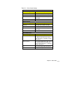
EDITION
PART NUMBER
DATE
First Edition
49.AA985.001
August 1996
Copyright © 1996 by Acer America Corporation. All rights reserved. No part of this publication may be
reproduced, transmitted, transcribed, stored in a retrieval system, or translated into any language or
computer language, in any form or by any means, electronic, mechanical, magnetic, optical, chemical,
manual or otherwise, without the prior written permission of Acer America Corporation.
Programs Copyright © 1996 Acer America Corporation.
All rights reserved.
Printed in U.S.A
Trademarks
Acer and the Acer logo are registered trademarks of Acer Incorporated.
AcerAltos is a trademark of Acer America Corporation and Acer Inc..
Adaptec and the Adaptec logo are registered trademarks of Adaptec, Inc. SCSISelect is a trademark of
Adaptec, Inc.
Intel and Pentium are registered trademarks of Intel Corporation.
IBM is a registered trademark and PS/2 is a trademark of International Business Machines Corporation.
MS-DOS and Windows NT are registered trademarks of Microsoft Corporation.
Mylex is a registered trademark of Mylex Corporation.
Novell and NetWare are registered trademarks of Novell Incorporated.
SCO and SCO UNIX are registered trademarks of The Santa Cruz Operation, Inc.
Other brand and product names are trademarks and/or registered trademarks of their respective holders.
Disclaimer
ii
Acer and its suppliers make no representations or warranties, either expressed or implied, with respect to the
contents hereof and specifically disclaim any warranties of merchantability or fitness for a particular purpose.
Further, Acer reserves the right to revise this publication and to make changes from time to time in the
contents hereof without obligation to notify any person of such revisions or changes. Acer reserves the right
to make changes to the products described in this manual at any time and without notice.
AcerAltos 19000 User’s Guide
Warranty/Limitation of Liability
Any software described in this manual is licensed “as is” and Acer and its suppliers disclaim any and
all warranties, express or implied, including but not limited to any warranty of non-infringement of
third party rights, merchantability or fitness for a particular purpose. Acer does not warrant that the
operation of the software will be uninterrupted or error free. Should the programs prove defective, the
buyer (and not Acer, its distributor, or its dealer) assumes the entire cost of all necessary service, repair,
and any incidental or consequential damages resulting from any defect in the software. Please see the
Acer Limited Product Warranty for details of Acer’s limited warranty on hardware products. IN NO
EVENT SHALL ACER BE LIABLE FOR ANY INDIRECT OR CONSEQUENTIAL DAMAGES,
INCLUDING LOSS OF PROFITS OR DATA, EVEN IF ACER HAS BEEN ADVISED OF THE
POSSIBILITY OF SUCH DAMAGES.
Software License
Acer grants you a personal, non-transferable, non-exclusive license to use the software that accompanies
your computer system only on a single computer. You may not (a) make copies of the software except
for making one (1) backup copy of the software which will also be subject to this license, (b) reverse
engineer, decompile, disassemble, translate or create derivative works based upon the software, (c)
export or re-export the software to any person or destination which is not authorized to receive them
under the export control laws and regulations of the United States, (d) remove or alter in any way the
copyright notices, or other proprietary legends that were on the software as delivered to you or (e)
sublicense or otherwise make the software available to third parties. The software is the property of
Acer or Acer’s supplier and you do not have and shall not gain any proprietary interest in the software
(including any modifications or copies made by or for you) or any related intellectual property rights.
Additional restrictions may apply to certain software titles. Please refer to any software licenses that
accompany such software for details.
iii
IMPORTANT SAFETY INSTRUCTIONS
1.
Read these instructions carefully. Save them for future reference.
2.
Follow all warnings and instructions marked on the product.
3.
Unplug this product from the wall outlet before cleaning. Do not use liquid
cleaners or aerosol cleaners. Use a damp cloth for cleaning.
4.
Do not use this product near water.
5.
Do not place this product on an unstable cart, stand, or table. The product
may fall, causing serious damage to the product.
6.
Slots and openings in the cabinet and the back or bottom are provided for
ventilation; to ensure reliable operation of the product and to protect it from
overheating, these openings must not be blocked or covered. This product
should never be placed near or over a radiator or heat register, or in a built-in
installation unless proper ventilation is provided.
7.
This product should be operated from the type of power indicated on the
marking label. If you are not sure of the type of power available, consult your
dealer or local power company.
8.
This product is equipped with a 3-wire grounding-type plug, a plug having a
third (grounding) pin. This plug will only fit into a grounding-type power
outlet. This is a safety feature. If you are unable to insert the plug into the
outlet, contact your electrician to replace the outlet. Do not defeat the
purpose of the grounding-type plug.
9.
Do not allow anything to rest on the power cord. Do not locate this product
where persons will walk on the cord.
10. If an extension cord is used with this product, make sure that the total
ampere rating of the equipment plugged into the extension cord does not
exceed the extension cord ampere rating. Also, make sure that the total
rating of all products plugged into the wall outlet does not exceed 15
amperes.
11. Never push objects of any kind into this product through cabinet slots as they
may touch dangerous voltage points or short out parts that could result in a
fire or electric shock. Never spill liquid of any kind on the product.
iv
AcerAltos 19000 User’s Guide
12. Do not attempt to service this product yourself, as opening or removing
covers may expose you to dangerous voltage points or other risks. Refer all
servicing to qualified service personnel.
13. Unplug this product from the wall outlet and refer servicing to qualified
service personnel under the following conditions:
a.
When the power cord or plug is damaged or frayed
b. If liquid has been spilled into the product
c.
If the product has been exposed to rain or water
d. If the product does not operate normally when the operating instructions
are followed. Adjust only those controls that are covered by the
operating instructions since improper adjustment of other controls may
result in damage and will often require extensive work by a qualified
technician to restore the product to normal condition.
e.
If the product has been dropped or the cabinet has been damaged
f.
If the product exhibits a distinct change in performance, indicating a need
for service
14. Use only the proper type of power supply cord (provided in your
keyboard/manual accessories box) for this unit. It should be a detachable
type: UL listed/CSA certified, type SJT, rated 12A 125V minimum.
Maximum length is 15 feet (4.6 meters).
v
FCC Class A Radio Frequency
Interference Statement
Note:
This equipment has been tested and found to comply with the limits for a Class A
digital device, pursuant to Part 15 of FCC Rules. These limits are designed to
provide reasonable protection against harmful interference in a residential
installation. This equipment generates, uses, and can radiate radio frequency
energy and, if not installed and used in accordance with the instructions, may
cause harmful interference to radio communications. However, there is no
guarantee that interference will not occur in a particular installation. If this
equipment does cause harmful interference to radio or television reception, which
can be determined by turning the equipment off and on, the user is encouraged to
try to correct the interference by one or more of the following measures:
1.
Reorient or relocate the receiving antenna.
2.
Increase the separation between the equipment and receiver.
3.
Connect the equipment into an outlet on a circuit different from that to which
the receiver is connected.
4.
Consult the dealer or an experienced radio/television technician for help.
Notice 1:
The changes or modifications not expressly approved by the party responsible for
compliance could void the user's authority to operate the equipment.
Notice 2:
Shielded interface cables, if any, must be used in order to comply with the
emission limits.
vi
AcerAltos 19000 User’s Guide
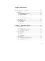
Table of Contents
Chapter 1
System Introduction............................................. 1-1
1.1 Features ...................................................................................................... 1-1
1.1.1 Intel Pentium Pro Processor........................................................... 1-1
1.1.2 System Architecture ....................................................................... 1-3
1.1.3 SCSI Subsystem............................................................................... 1-5
1.1.4 Server Management........................................................................ 1-5
1.1.5 Redundant Power Supply Subsystem........................................... 1-6
1.16
Security............................................................................................ 1-6
1.2 External Configuration.............................................................................. 1-7
1.2.1 Front Panel ...................................................................................... 1-7
1.2.2 Rear Panel...................................................................................... 1-13
Chapter 2
Setting Up the System ......................................... 2-1
2.1 Pre-Installation........................................................................................... 2-1
2.1.1 Selecting a Site................................................................................. 2-1
2.1.2 Checking the Package Contents..................................................... 2-2
2.1.3 Preparing the System Unit ............................................................. 2-3
2.2 Basic Connections...................................................................................... 2-5
2.2.1 Keyboard ......................................................................................... 2-5
2.2.2 Mouse .............................................................................................. 2-6
2.2.3 VGA Monitor .................................................................................. 2-7
2.3 System Startup........................................................................................... 2-8
2.3.1 Unlocking the Front Panel Security............................................... 2-8
2.3.2 Turning On the System Power ...................................................... 2-9
2.4 Power-on Problems ................................................................................. 2-10
vii
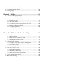
Chapter 3
System Housing....................................................3-1
3.1 Internal Structure .......................................................................................3-1
3.2 Removing the Housing Doors...................................................................3-4
3.3 SCSI Backplane Boards..............................................................................3-8
3.3.1 Features............................................................................................3-8
3.4 Front Panel Board ......................................................................................3-9
3.5 Power Subsystem .....................................................................................3-10
3.6 ESD Precautions.......................................................................................3-10
3.7 Installing Additional Devices..................................................................3-11
3.8 Installing an Expansion Board ................................................................3-13
Chapter 4
System Board........................................................4-1
4.1 Major Components ....................................................................................4-1
4.1.1 Layout ..............................................................................................4-2
4.1.2 Jumpers and Connectors ................................................................4-3
4.1.3 Installing a Pentium Pro Processor................................................4-8
4.2 Memory Board .........................................................................................4-10
4.2.1 Layout ............................................................................................4-10
4.2.2 Rules for Adding Memory ...........................................................4-11
4.2.3 Memory Configurations ...............................................................4-12
4.2.4 Installing a SIMM..........................................................................4-13
4.2.5 Removing a SIMM ........................................................................4-14
4.2.6 Installing the Memory Board .......................................................4-15
4.2.7 Reconfiguring the System.............................................................4-17
Chapter 5
BIOS Utility ............................................................5-1
5.1 Entering Setup............................................................................................5-2
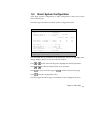
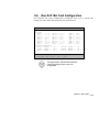
5.2 Basic System Configuration ......................................................................5-3
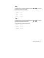
5.2.1 Date and Time .................................................................................5-4
5.2.2 Diskette Drives................................................................................5-6
viii
AcerAltos 19000 User’s Guide
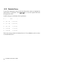
5.2.3 Hard Disk Drives............................................................................ 5-7
5.2.4 System Memory .............................................................................. 5-9
5.2.5 Math Coprocessor........................................................................... 5-9
5.2.6 Video Display.................................................................................. 5-9
5.2.7 Communication Settings .............................................................. 5-10
5.2.8 Enhanced IDE Features ................................................................ 5-11
5.2.9 Large Memory Support Mode..................................................... 5-11
5.2.10 Num Lock After Boot................................................................... 5-11
5.2.11 Memory Test ................................................................................. 5-12
5.2.12 Auto Configuration Mode ........................................................... 5-12
5.2.13 Fast Boot Mode ............................................................................. 5-12
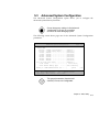
5.3 Advanced System Configuration ........................................................... 5-13
5.3.1 Shadow RAM................................................................................ 5-14
5.3.2 L1 and L2 Cache (CPU Cache) .................................................... 5-14
5.3.3 Memory at 15MB-16MB ............................................................... 5-15
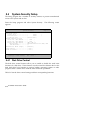
5.4 System Security Setup ............................................................................. 5-16
5.4.1 Disk Drive Control ....................................................................... 5-16
5.4.2 Onboard Communication Ports .................................................. 5-18
5.4.3 Onboard PS/2 Mouse (IRQ12) .................................................... 5-20
5.4.4 Setup Password ............................................................................ 5-21
5.4.5 Power On Password ..................................................................... 5-22
5.5 PCI System Configuration ...................................................................... 5-23
5.5.1 PCI IRQ Setting............................................................................. 5-23
5.5.2 VGA Palette Snoop ....................................................................... 5-24
5.5.3 Onboard SCSI................................................................................ 5-24
5.6 Non-PnP ISA Card Configuration.......................................................... 5-25
5.6.1 IRQ/DMA ..................................................................................... 5-27
5.6.2 Expansion ROM Region ............................................................... 5-27
5.6.3 I/O Region .................................................................................... 5-27
5.6.4 Local Memory Region .................................................................. 5-27
ix
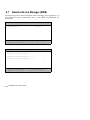
5.7 Remote Device Manager (RDM).............................................................5-28
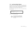
5.8 Load Setup Default Settings....................................................................5-29
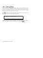
5.9 Leaving Setup...........................................................................................5-30
Chapter 6
Utilities...................................................................6-1
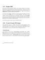
6.1 Acer Server Manager (ASM) Pro..............................................................6-1
6.2 Remote Device Manager (RDM)...............................................................6-2
6.3 EISA Configuration Utility (ECU) ............................................................6-3
6.3.1 Starting the ECU .............................................................................6-6
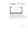
6.3.2 ECU Main Menu .............................................................................6-7
6.3.3 Configuring Your Computer for the First Time .........................6-14
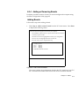
6.3.4 Adding or Removing Boards .......................................................6-17
6.3.5 Configuring Memory ....................................................................6-20
6.3.6 Viewing or Editing Configuration Details ..................................6-23
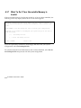
6.3.7 What To Do If Your Nonvolatile Memory is Invalid .................6-26
Chapter 7
SCSISelect Configuration Utility..........................7-1
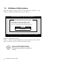
7.1 The SCSISelect Utility.................................................................................7-1
7.1.1 Default Values .................................................................................7-1
7.1.2 When to Use the SCSISelect Utility ................................................7-3
7.1.3 Running the SCSISelect Utility........................................................7-3
7.2 SCSISelect Utility Options..........................................................................7-4
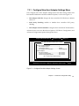
7.2.1 Configure/View Host Adapter Settings Menu ............................7-5
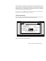
7.2.2 SCSI Disk Utilities .........................................................................7-20
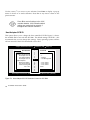
7.3 Configuring Multiple SCSI Controllers..................................................7-22
7.4 Disk Drives Over 1 Gbyte .......................................................................7-23
7.4.1 Extended Translation....................................................................7-23
7.4.2 The DOS 1 Gbyte Limit.................................................................7-23
7.4.3 When to Use Extended Translation.............................................7-24
7.5 SCSI Troubleshooting Checklist..............................................................7-25
7.6 BIOS Startup Messages .............................................................................7-26
x
AcerAltos 19000 User’s Guide
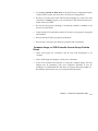
Appendix A System Resources ...............................................A-1
A.1 Memory Map ............................................................................................ A-1
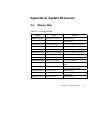
A.2 I/O Address Map..................................................................................... A-2
A.3 Interrupt Channels ................................................................................... A-4
A.4 System Default Configuration ................................................................. A-5
Appendix B SCSI Backplane Boards.......................................B-1
B.1 Features ......................................................................................................B-1
B.2 Layout.........................................................................................................B-2
B.3 Jumper Settings..........................................................................................B-3
B.4 Hard Disk ID Feature................................................................................B-4
B.5 Channel Configuration..............................................................................B-5
B.6 Installing a SCSI Hard Disk ......................................................................B-8
B.7 Using the Hot-swap Feature...................................................................B-12
Appendix C Power Subsystem ................................................C-1
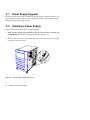
C.1 Power Supply Upgrade............................................................................ C-2
C.2 Installing a Power Supply ........................................................................ C-2
C.3 Removing a Power Supply Module ........................................................ C-7
C.4 Power Cable Connections ........................................................................ C-9
C.5 Installing a Charger Board and a Battery Box...................................... C-12
INDEX
xi
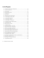
List of Figures
1-1 Pentium Pro Processor Architecture ........................................................1-2
1-2 System Architecture...................................................................................1-3
1-3 Front Panel..................................................................................................1-7
1-4 Front Panel Features ..................................................................................1-8
1-5 RDM Button .............................................................................................1-12
1-6 Rear Panel .................................................................................................1-13
2-1 Front Lever and Support Pole...................................................................2-3
2-2 Connecting the Power Cable.....................................................................2-4
2-3 Connecting a Keyboard .............................................................................2-5
2-4 Connecting A Mouse .................................................................................2-6
2-5 Connecting a VGA Monitor ......................................................................2-7
2-6 Unlocking the Front Panel Security ..........................................................2-8
2-7 System Power On.......................................................................................2-9
2-8 Microswitch Location ..............................................................................2-12
3-1 System Housing .........................................................................................3-1
3-2 Left Panel System Components ................................................................3-2
3-3 Right Panel System Components..............................................................3-3
3-4 Removing the Right Panel Door ...............................................................3-5
3-5 Removing the Upper Front Panel Cover..................................................3-6
3-6 Removing the Upper Front Panel Door ...................................................3-6
3-7 Removing the Lower Front Panel Door ...................................................3-7
3-8 Front Panel Board Connections ................................................................3-9
3-9 Attaching the Drive Guides ....................................................................3-11
3-10 Installing an Additional Externally-Accessible Device.........................3-12
3-11 Removing a Bracket Cover......................................................................3-13
3-12 Installing a PCI Expansion Board ...........................................................3-14
4-1 System Board Layout.................................................................................4-2
xii
AcerAltos 19000 User’s Guide
4-2 Jumper and Connector Locations............................................................. 4-3
4-3 VRM Settings for CPU1 (3.3V for 200 MHz) ........................................... 4-5
4-4 VRM Settings for CPU2 (3.3V for 200 MHz) ........................................... 4-5
4-5 Clock Frequency Ratio Setting (CN15) .................................................... 4-7
4-6 Attaching the Heat Sink to the CPU ........................................................ 4-8
4-7 Installing a Pentium Pro Processor .......................................................... 4-9
4-8 Memory Board Layout............................................................................ 4-10
4-9 Installing a SIMM .................................................................................... 4-13
4-10 Removing a SIMM................................................................................... 4-14
4-11 Inserting the Memory Board .................................................................. 4-15
4-12 Attaching the Board Holding Clamp..................................................... 4-16
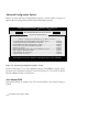
6-1 ECU Main Menu Steps in Configuring Your Computer ................... 6-7
6-2 Important EISA Configuration Information............................................ 6-8
6-3 Add or Remove Boards........................................................................... 6-10
6-4 View or Edit Details ................................................................................ 6-11
6-5 Examine Switches or Print Report ......................................................... 6-12
6-6 Save and Exit............................................................................................ 6-13
6-7 Examine Switches or Print Report ......................................................... 6-14
6-8 Save and Exit............................................................................................ 6-16
6-9 Add or Remove Boards........................................................................... 6-17
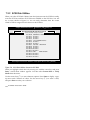
7-1 Options Menu Screen ................................................................................ 7-4
7-2 Configure/View Host Adapter Settings Screen...................................... 7-5
7-3 Host Adapter SCSI ID Selection Screen for AIC-7880 ............................ 7-6
7-4 SCSI Parity Checking Selection ................................................................ 7-7
7-5 Host Adapter SCSI Termination Selection for AIC-7880 ....................... 7-9
7-6 Boot Device Options Screen.................................................................... 7-10
7-7 SCSI Device Configuration Screen for AIC-7880 .................................. 7-11
7-8 Advanced Configuration Options Screen.............................................. 7-16
7-9 SCSI Disk Utilities Screen for AIC-7880................................................. 7-20
B-1 SCSI Backplane Board ...............................................................................B-2
xiii
B-2 Jumper J3 Settings ..................................................................................... B-3
B-3 Jumper J4 Settings ..................................................................................... B-3
B-4 P3 Setting for Jumper J4............................................................................ B-4
B-5 Single-Channel Configuration.................................................................. B-5
B-6 Dual-Channel Configuration.................................................................... B-7
B-7 Unlocking the Drive Tray Switch ............................................................ B-8
B-8 Pulling Out a Hot-plug Drive Tray ......................................................... B-9
B-9 Connecting the Drive Cables (Wide SCSI Drive) ................................. B-10
B-10 Installing a Hot-plug Drive Tray ........................................................... B-11
B-11 Locking the Drive Tray Switch .............................................................. B-12
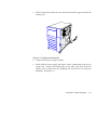
C-1 Removing the Metal Bar Screws ..............................................................C-2
C-2 Pulling Out the Metal Bar.........................................................................C-3
C-3 Installing a Power Supply Module ..........................................................C-4
C-4 Locking the Holding Clips .......................................................................C-4
C-5 Reinstalling the Metal Bar ........................................................................C-5
C-6 Securing the Metal Bar with Screws........................................................C-6
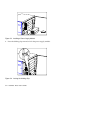
C-7 Unlocking the Power Supply Holding Clips ..........................................C-7
C-8 Removing the Power Supply Module .....................................................C-8
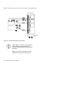
C-9 System Board Power Connections......................................................... C-10
C-10 System Board and Power Subsystem Interconnections ....................... C-11
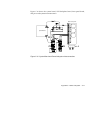
C-11 Removing the Charger Compartment Metal Cover............................. C-13
C-12 Installing a Charger Board ..................................................................... C-14
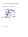
C-13 Locking the Charger Board .................................................................... C-15
C-14 Installing a Battery Box........................................................................... C-16
C-15 Attaching the Charger Compartment Metal Cover ............................. C-17
C-16 Removing a Battery Box ......................................................................... C-18
xiv
AcerAltos 19000 User’s Guide
List of Tables
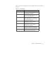
1-1 LED Indicator Description...................................................................... 1-10
1-2 LCD Messages ......................................................................................... 1-11
3-1 Removing the Housing Doors .................................................................. 3-4
4-1 Jumper Settings.......................................................................................... 4-4
4-2 Voltage Identification Codes .................................................................... 4-6
4-3 Connector Functions ................................................................................. 4-7
4-4 Memory Configurations.......................................................................... 4-12
5-1 Drive Control settings ............................................................................. 5-17
5-2 Serial Port 1 Settings................................................................................ 5-18
5-3 Serial Port 2 Settings................................................................................ 5-18
5-4 Parallel Port Settings ............................................................................... 5-19
5-5 Parallel Port Operation Mode Settings .................................................. 5-20
6-1 Keyboard Function Keys........................................................................... 6-4
7-1 Default Settings for SCSI Controller and All Devices ............................ 7-2
A-1 System Memory Map ............................................................................... A-1
A-2 System I/O Address Map........................................................................ A-2
A-3 Interrupt Channels ................................................................................... A-4
A-4 Basic System Configuration (Page 1) ...................................................... A-5
A-5 Basic System Configuration (Page 2) ...................................................... A-5
A-6 Advanced System Configuration (Page 1).............................................. A-6
A-7 PCI System Configuration ....................................................................... A-7
A-8 System Security......................................................................................... A-8
A-9 EISA Configuration Utility - ECU........................................................... A-9
B-1 P3 Settings and Functions .........................................................................B-4
B-2 Terminator Settings for Single-Channel Configuration..........................B-6
B-3 Terminator Settings for Dual-Channel Configuration............................B-7
C-1 Power Backplane Connections ................................................................ C-9
xv
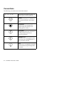
Conventions
The following conventions are used in this manual:
a, e, s, etc.
Represents the actual keys that you
have to press on the keyboard.
NOTE
Gives bits and pieces of additional
information related to the current
topic.
WARNING
Alerts you to any damage that
might result from doing or not
doing specific actions.
CAUTION
Suggests precautionary measures to
avoid potential hardware or
software problems.
IMPORTANT
Reminds you to take specific action
relevant to the accomplishment of
the procedure at hand.
TIP
Tells how to accomplish a procedure
with minimum steps through little
shortcuts.
xvi
AcerAltos 19000 User’s Guide
Chapter 1
1.1
System Introduction
Features
The AcerAltos 19000 is a powerful 64-bit dual-processor capable system loaded
with a host of new and innovative features. The system offers a new standard for
flexible productivity ideal for local area networks and multiuser server
environments.
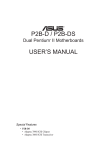
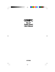
1.1.1 Intel Pentium Pro Processor
The Intel Pentium Pro processor is the heart of the AcerAltos 19000 system.
Designed to work with the Intel 450 PCIset composed of a PCI bridge and
memory controller, the Pentium Pro running at 200 MHz carries a new generation
of power not present in its predecessors.
The system board has two CPU sockets to accommodate two Intel Pentium Pro
processors for a dual-processor configuration. In this configuration Symmetric
MultiProcessing (SMP) significantly increases overall system performance. The
AcerAltos 19000 system supports a wide range of applications running under MP
operating systems such as WindowsNT, UNIX, and NetWare.
The CPU also incorporates first-level (L1) and second-level (L2) caches, an
advanced peripheral interrupt controller (APIC), and the system bus controller.
Figure 1-1 shows the CPU architecture.
First-level and Second-level Cache
The Pentium Pro design integrates both 16-KB first-level and 256 KB second-level
cache. These caches produce high hit rates that reduce the processor’s external
memory bandwidth requirements.
Chapter 1 - System Introduction 1-1
Advanced Peripheral Interrupt Controller (APIC)
The APIC unit inside the CPU, along with an I/O APIC unit, facilitates
multiprocessor interrupt management. The APIC works with multiple I/O
subsystems where each subsystem has its own interrupts which help minimize
centralized system overhead.
Bus Controller
The bus controller integrated in the Pentium Pro processor controls the system
bus, allowing it to efficiently perform its functions. It ensures the bus serves as a
reliable interconnection between one or two CPUs, I/O bridge, and memory
controllers.
Pentium Pro Processor Architecture
CPU Core
8-KB 2-way
Data Cache
8-KB 4-way
Code Cache
256KB 4-way L2 Cache
APIC
Bus Controller
Figure 1-1 Pentium Pro Processor Architecture
1-2 AcerAltos 19000 User’s Guide
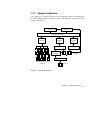
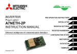
1.1.2
System Architecture
The system bus, PCI buses, EISA bus, PCI bridge (PB), memory controller (MC),
PCI/EISA Bridge (PCEB), and EISA system controller (ESC) comprise the basic
system architecture.
Pentium Pro CPU 1
256 Cache
Pentium Pro CPU 2
256 Cache
64-bit Pentium Pro MP Bus
DC/DP/MIC
3
2
1
1
1
2
1
2
1
PCI Bus 1 132MB/s
PCI Bus 2 132MB/s
2
3
4
5
6
APIC Bus
PCI Slots
1
2
5
1
PCI/EISA Bridge
(PCEB/ESC)
2
1
2
6
PCI Bridge
(PB)
1
2
1
2
7
0
PCI Bridge
(PB)
2
EISA Bus 32MB/s
4
4-way Interleave ECC Memory
SIMM * 16
1
2
3
EISA Slots
Figure 1-2 System Architecture
Chapter 1 - System Introduction 1-3
System Bus
The system bus is the CPU’s major connection to all the system devices, primarily
the PCI and EISA bridges, and the memory controller. It can handle as many as
eight outstanding transactions at a time through a transaction pipelining feature,
in which consecutive tasks from the CPU are queued in and transported to the
designated devices on a first-in first-out basis. Pipelining allows for transaction
overlapping in different phases, as the CPU does not have to wait for each to
complete before it issues the next transaction. This produces significant
improvement in overall system performance.
The bus architecture supports a number of features that ensure high reliability. It
has an 8-bit error correction code (ECC) that protects the data lines and a 2-bit
parity code that protects the address lines.
The bus uses Gunning Transceiver Logic (GTL+) and a synchronous latched bus
protocol that simplifies timing constraints. This protocol supports higher
frequency system designs and along with GTL+, requires a low voltage which
reduces electromagnetic interference (EMI) resulting in a lower power
consumption.
PCI and EISA Buses
The system supports two PCI buses created by the two PCI bridge chips (PB).
The PCI buses serve as links between the PCI bridges and PCI devices onboard.
The presence of two buses instead of one reduces I/O bottlenecks and matches
the higher bandwidth of the CPU for faster data transfers.
The EISA bus connects EISA devices to other system devices through the
PCI/EISA bridge (PCEB) and the EISA system controller (ESC). The use of the
PCEB and ESC maintain compatibility within the EISA environment.
1-4 AcerAltos 19000 User’s Guide
PCI Bridge (PB)
The PCI Bridge (PB) is an I/O subsystem solution for high-performance systems.
The PB translates transactions between the system bus and the PCI buses using
32-byte buffers for inbound and outbound posting. The use of two PBs in the
system creates an architecture that allows even faster data transfers.
Memory Controller (MC)
The memory controller (MC) acts as an interface between the system bus and
system memory. It consists of the DRAM control (DC) chip and the data
path (DP) chip. The MC connects to the DRAM array through four memory
interface controller (MIC) chips. The MC supports 256-bit 4-way memory
interleaving resulting in more efficient memory traffic management.
1.1.3 SCSI Subsystem
The AcerAltos 19000 system supports an array of 14 hot-pluggable disk drive
trays through two 7-slot SCSI backplane boards. The trays accommodate wide
SCSI hard disks. With an onboard AIC-7880 SCSI controller, the burst transfer
rate can reach 20 MB per second.
1.1.4 Server Management
Acer Server Manager (ASM) Pro, a server management feature, monitors voltage
and CPU thermal stability, prevents data loss by prompt ECC memory error
reporting, maximizes system resources by indicating PCI bus utilization, and
promotes efficiency by minimizing system downtime. If this feature has been
implemented, refer to the Acer Server Manager (ASM) Pro User’s Guide for
information.
Remote Device Manager (RDM) permits system diagnosis from a remote site
through a modem. RDM facilitates fixing of certain detected problems, changing
system configuration or rebooting in the event of system failure. If this feature
has been implemented, refer to the RDM documentation for information.
Chapter 1 - System Introduction 1-5
1.1.5
Redundant Power Supply Subsystem
The system ships with two load-sharing power supply modules. Load sharing
significantly extends the life of the power supplies. The power subsystem also
supports a redundant configuration such that if one power supply fails, the other
continues to provide system power.
A third power supply module is available as an option. This power supply
module is redundant, but not load-sharing; however, if either the primary or
secondary power supply module fails, the third power supply module load
shares with the remaining power supply module.
An important segment of the power subsystem is the optional battery module.
Providing backup support to the power supply modules, the battery
automatically charges whenever the system is on. This gives a fully-configured
system the ability to run through short interruptions in wall power or to continue
supplying system power for up to eight minutes in the event of total AC power
failure.
1.1.6 Security
The system housing comes with mechanical security locks on both the front panel
and the side panels, preventing unauthorized access to the internal components.
The system BIOS secures the CMOS data and other system software with poweron password, keyboard password, setup control, disk drive control, and monitor
control.
1-6 AcerAltos 19000 User’s Guide
1.2
External Configuration
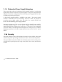
1.2.1 Front Panel
The system front panel is divided into two sections. The upper front panel
consists of the diskette/CD-ROM/tape drive bays, keylock, power switch, LED
indicators, LCD display screen, and an embedded reset switch.
The lower section contains externally accessible hard disk drive bays and drive
trays for wide SCSI drives. The AcerAltos 19000 ships with 7 drive trays in the
left side.
Figure 1-3 Front Panel
The system keys are inside the front panel.
Chapter 1 - System Introduction 1-7
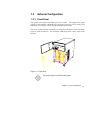
Front Panel Features
Figure 1-4 gives a closer look at the upper front panel features.
LED Indicators
LCD Display Screen
5.25-inch
Drive Bays
CD-ROM Drive
Power Switch
Reset Switch
(embedded)
3.5-inch
Diskette Drive
Keylock
Figure 1-4 Front Panel Features
CD-ROM Drive
The basic system comes with a SCSI CD-ROM drive already installed.
3.5-inch Diskette Drive
A 3.5-inch diskette drive also comes with the basic system.
1-8 AcerAltos 19000 User’s Guide
5.25-inch Drive Bays
Two empty 5.25-inch drive bays allow installation of additional externallyaccessible devices.
Power Switch
The power switch allows you to turn the system power on or off.
Reset Switch
Pressing the reset switch generates a hardware reset pulse that restarts the system
initializing all the registers, buffers, and memory subsystems.
Keylock
The keylock gives security to the system against unauthorized users. Turning the
keylock to the unlocked position enables the power and reset switches. Turning
the keylock to the locked position disables both switches whether the system is on
or off. Supposing the system is on and you intend to reset or turn it off, make
sure that the keylock is unlocked. Otherwise, the switches do not respond.
Chapter 1 - System Introduction 1-9
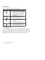
LED Indicators
Table 1-1
LED Indicator Description (Right to Left)
LED Icons
Power Status
Battery Status
UPS
Hard Disk Failure
Hard Disk Busy
Description
Green
Indicates that power is on. All the power
supply modules are in good condition
and the system is running on AC power.
Red
Indicates that power is on, but AC has
failed and the system is running on
battery power.
Green
Indicates that a battery is present.
Red
Indicates low battery power.
Green
Indicates that all the hard disks installed
in the backplane board are in good
condition.
Red
Indicates that one of the hard disks
installed in the backplane board is bad.
Green
Indicates that at least one of the hard
disks is currently being accessed.
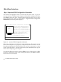
LCD Display Screen
The LCD display is a two-line by 16-character screen that indicates the boot status
as well as any BIOS check point errors encountered upon system initialization.
Normally, the system BIOS and the microcontroller firmware send the LCD
display messages that appear on the screen. However, if you hook up a special
purpose driver to control the LCD module, this driver defines the messages.
1-10 AcerAltos 19000 User’s Guide
Table 1-2 lists the LCD messages from the system BIOS and the microcontroller at
power on.
Table 1-2
LCD Messages
Message
Description
Hello! Welcome !
This is the first message that appears on the
LCD screen. This message indicates that the
microcontroller is operational.
POST Checkpoints
During system Power-On Self-Test (POST),
the LCD screen shows which POST checkpoint is currently being tested.
Power #1 Fails !
After POST, the microcontroller checks the
power subsystem status. If it detects that
power supply module 1 is bad, it sends this
message to the LCD screen.
Power #2 Fails !
If the microcontroller detects that power
supply module 2 is bad, it sends this
message to the LCD screen.
Power #3 Fails !
If the microcontroller detects that power
supply module 3 is bad, it sends this
message to the LCD screen.
Battery Low !
This message indicates that battery power is
running out. When this message appears,
shutdown the system as soon as possible.
Power Fan Fails !
This message indicates that one or more
fans of the power subsystem failed.
Chapter 1 - System Introduction 1-11
Table 1-2
LCD Messages (continued)
Message
Description
AC Power Fails !
When this message appears, it indicates
there is no power coming from the AC line
and the system is currently running on
battery power.*
AcerAltos 19000
This message appears after POST and other
system initialization tests, indicating the
system is up and running.
* An optional UPS provides a reliable power backup in case of a total AC power loss. To
use the UPS feature, you must have Acer Server Manager (ASM) Pro software installed.
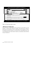
RDM Button
The RDM button located on the lower right panel enables Remote Device
Manager (RDM). If this feature has been implemented, refer to the RDM
documentation for information .
RDM Icon
RDM Button
1-12 AcerAltos 19000 User’s Guide
Figure 1-5 RDM Button
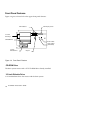
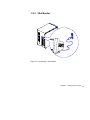
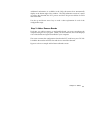
1.2.2 Rear Panel
The rear panel includes connectors for the keyboard, mouse, VGA monitor,
printer, and serial devices. Below these connectors are slot openings for
expansion boards. On the lower left is the power cable socket.
Keyboard Port
Mouse Port
Serial Port 2
Serial Port 1
Video Port
Parallel Port
Power Socket
Expansion Slot Bracket
Figure 1-6 Rear Panel
Chapter 1 - System Introduction 1-13
1-14 AcerAltos 19000 User’s Guide
Chapter 2
2.1
Setting Up the System
Pre-installation
2.1.1 Selecting a Site
Before unpacking and installing the system, select a suitable site for the maximum
efficiency of the system. The system is suitable for set up in an office
environment.
Consider the following factors when choosing a site for the system:
•
Near a grounded power outlet
•
Clean and dust-free
•
Sturdy surface free from vibration
•
Well-ventilated and away from sources of heat
•
Secluded from electromagnetic fields produced by electrical devices such as
air conditioners, radio and TV transmitters, etc.
Chapter 2 - Setting Up the System 2-1
2.1.2 Checking the Package Contents
Check the following items from the package:
•
AcerAltos 19000 System
•
AcerAltos 19000 User’s Guide (this manual)
•
Acer StartUp CD Software Kit
•
Acer Server Manager (ASM) Pro User’s Guide (if this feature has been
implemented)
•
Remote Device Manager (RDM) documentation (if this feature has been
implemented)
•
System keys (inside front panel)
If any of the above items is damaged or missing, contact your dealer immediately.
Save the boxes and packing materials for future use.
2-2 AcerAltos 19000 User’s Guide
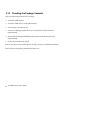
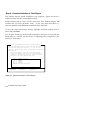
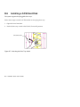
2.1.3 Preparing the System Unit
Do the following to begin setting up the system:
1.
Unlock the front wheels and move the system to your desired site.
The system housing design allows for easy transport in spite of its size. It
comes with four wheels that facilitate short-distance transits. The two front
wheels each include a lever to lock the wheels after you have positioned the
system into place. Beside the front wheels are two adjustable support poles
that add stability to the system.
Support Pole
Front Wheel Lever
Raise
Unlock
Lower
Lock
Figure 2-1 Front Wheel Lever and Support Pole
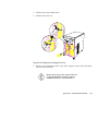
2.
After moving, lock the wheels by pressing down the levers. Turn the heads
of the support poles to the left until they reach the ground. These steps
ensure that the system is stable.
Make sure to unlock the wheels and raise the
support poles if you want to move the system
again.
Chapter 2 - Setting Up the System 2-3
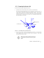
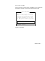
3.
Connect the power cable to the power socket on the rear panel and connect
the other end to a grounded outlet.
Figure 2-2 Connecting the Power Cable
2-4 AcerAltos 19000 User’s Guide
2.2
Basic Connections
The system unit, keyboard, mouse, and monitor constitute the basic system.
Connect these peripherals first to test for basic system functionality before
connecting other peripherals.
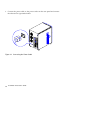
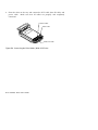
2.2.1 Keyboard
Figure 2-3 Connecting a Keyboard
Chapter 2 - Setting Up the System 2-5
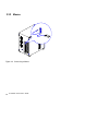
2.2.2 Mouse
Figure 2-4 Connecting a Mouse
2-6 AcerAltos 19000 User’s Guide
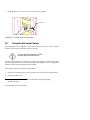
2.2.3 VGA Monitor
Figure 2-5 Connecting a VGA Monitor
Chapter 2 - Setting Up the System 2-7
2.3
System Startup
After making sure that you have set up the system properly and connected all the
required cables, you may now unlock the front panel security (as described
below) and apply power to the system.
2.3.1 Unlocking the Front Panel Security
The system has a keylock on the front panel to prevent unauthorized use. Before
powering on, open the lock with the key that comes with the system. (The system
keys are inside the front panel.)
To unlock, insert the key and turn it counter-clockwise until it reaches the
unlocked icon.
Locked Icon
Unlocked Icon
Figure 2-6 Unlocking the Front Panel Security
After locking or unlocking, remove the key
from the front panel to prevent unauthorized
users from tampering with the system.
2-8 AcerAltos 19000 User’s Guide
2.3.2 Turning On the System Power
To power on the system, press the power switch on the front panel. The system
starts up and displays a welcome message, then a series of Power-On Self-Test
(POST) messages on the LCD display screen. The POST messages indicate if the
system is running well or if it failed any of the tests. See Table 1-2 for a list of the
LCD messages.
If the system does not turn on or boot after
pressing the power switch, go to the next
section for the possible causes of the boot
failure.
Power Switch
Figure 2-7 System Power On
Chapter 2 - Setting Up the System 2-9
Aside from the self-test messages, you can determine if the system is in good
condition by checking if the following occurred:
•
Power indicator LED on the front panel lights up
•
Power, Num Lock, and Caps Lock LED indicators on the keyboard light up
2.4
Power-on Problems
If the system does not boot after you have applied power, check the following
factors that might have caused a boot failure.
The pointing symbol ( ☛ ) indicates a possible cause of the problem. The check
mark ( ✔ ) tells you how to correct the problem.
☛ The front panel is not completely unlocked.
✔
Insert the front panel key and turn it counter-clockwise until it points to the
unlocked icon. See Figure 2-6.
☛ The external power cable may be loose.
✔
Check the power cable connection from the power source to the power socket
on the rear panel. Make sure that the cable is properly connected.
☛ No power comes from the grounded power outlet.
✔
Have an electrician check your power outlet.
☛ The right panel or left panel door, or both, may be ajar.
✔
Close the panel door(s) completely.
2-10 AcerAltos 19000 User’s Guide
The system has two microswitches located inside the lower front corners of the
housing. The microswitches connect to the power backplane and are in direct
contact with the left and right panel doors. When you open either one of the
panel doors, the microswitch goes off thereby cutting off system power. This
provides additional system security against unauthorized access.
See Figure 2-8 for the microswitch location.
Chapter 2 - Setting Up the System 2-11
J14 from the
Power Backplane
Microswitch Cable
Microswitch
Figure 2-8 Microswitch Location
☛ Loose or improperly connected internal power cables.
✔
Refer to Appendix C for the power cable connections and check the internal
cable connections. If you are not confident you can perform this step, ask a
qualified technician to help you.
If you have gone through the preceding
actions and the system still fails to boot, ask
your dealer or a qualified technician for
assistance.
2-12 AcerAltos 19000 User’s Guide
Chapter 3
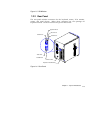
System Housing
The system housing is heavy-duty steel chassis in a twin-tower design. The
spacious housing boasts high expansion capability and flexible configuration.
Figure 3-1 System Housing
3.1
Internal Structure
The housing is symmetrically divided into left and right panels. The system
internal components are accessible through the panels.
Chapter 3 - System Housing 3-1
Left Panel
The main part of the left panel houses the system board, memory board, and
expansion boards. In the rear section of the left panel are the keyboard, mouse,
video, parallel, and serial ports, and the slot openings for installation of EISA and
PCI expansion boards.
The upper front section of the left panel accommodates a 3.5-inch and three 5.25inch drives while the lower section holds the seven hot-pluggable SCSI drive
trays. These devices on the front section are externally accessible. Right behind
the drives is a seven-slot SCSI backplane board that connects the drives to the
SCSI interface.
Figure 3-2 shows the system components inside the left panel of the system
housing.
5.25-inch Drive Bays
Slot Openings
3.5-inch Drive Bay
SCSI Drive Trays
System Board
Figure 3-2 Left Panel System Components
3-2 AcerAltos 19000 User’s Guide
Backplane Board
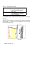
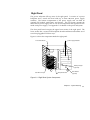
Right Panel
The power subsystem fills up most of the right panel. It consists of a power
backplane and a metal rack that holds up to three 400-watt power supply
modules. The bottom compartment of the power supply rack can hold an
optional UPS module with battery and charger. The rear section contains the
three built-in power supply fans to cool down components and regulate air flow
inside each power supply. See Appendix C for details on the power subsystem.
The front panel board occupies the upper front section of the right panel. The
lower section has a second SCSI backplane board installation and another set of
seven hot-pluggable SCSI drive trays.
Figure 3-3 shows the components inside the right panel.
Power Supply Modules
Front Panel Board
Battery Charger
(optional)
SCSI Drive Trays
Backplane Board
UPS Module
(optional)
Figure 3-3 Right Panel System Components
Chapter 3 - System Housing 3-3
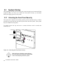
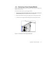
3.2
Removing the Housing Doors
The system housing has four doors, two on the front, one on the left panel, and
one on the right panel. The left and right panel doors have security locks to
prevent unauthorized access to the internal components.
Turn off the system and disconnect the AC power cord before
opening the system housing.
When installing components, unlock and remove the door or doors that hinder
your way. Table 3-1 tells you which door to remove in specific instances to
facilitate component installation.
Table 3-1
Removing the Housing Doors
When
Installing or removing external 3.5-inch
or 5.25-inch devices
Remove
$Upper front door plus
the upper front panel
cover
%Left panel door
Installing or removing a SCSI backplane
board (left side)
$Lower front door
Installing or removing a SCSI backplane
board (right side)
$Lower front door
Installing or removing hot-pluggable
SCSI hard disks
$Lower front door
Installing or removing the system board,
memory board, or expansion boards
$Left panel door
Installing or removing the power supply
modules, UPS, or battery charger
$Right panel door
Connecting or arranging cables
$Left panel door
%Left panel door
%Right panel door
or
Right panel door
3-4 AcerAltos 19000 User’s Guide
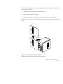
The doors are attached to the main housing by screwless hinges. Follow these
steps to remove a door.
1.
Unlock the door with the key (when necessary).
2.
Open it to more than a 45° angle.
3.
Lift it up for about an inch, then move the door away from the housing.
Figures 3-4 to 3-7 show how to remove the housing doors and upper front panel
cover.
Figure 3-4 Removing the Right Panel Door
Follow the same steps to remove the left panel door.
Chapter 3 - System Housing 3-5
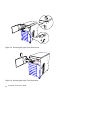
2
1
Figure 3-5 Removing the Upper Front Panel Cover
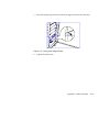
Figure 3-6 Removing the Upper Front Panel Door
3-6 AcerAltos 19000 User’s Guide
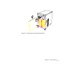
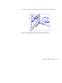
Figure 3-7 Removing the Lower Front Panel Door
Chapter 3 - System Housing 3-7
3.3
SCSI Backplane Boards
There are two SCSI backplane boards standard in the AcerAltos 19000. This
section gives a brief description of the boards. Refer to Appendix B for a detailed
discussion, including information about backplane board major components,
jumper settings, hard disk ID feature, and channel configurations (single- and
dual-channel).
The SCSI backplane boards provide a convenient interface between the SCSI
drives and the system board. Each board includes seven SCSI drive slots to
accommodate the drive trays, two SCSI channels to connect to the system board
or SCSI controller board, and one SCSI channel out for external devices.
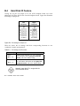
3.3.1 Features
Each backplane board has the following major features:
•
“Hot-swap” feature that allows replacement of a defective hard drive even
while the system is in full operation. This feature requires a RAID controller
board and RAID drivers.
•
Indicates hard disk drive failure through a front panel board LED
•
Supports wide SCSI disk drives
•
Each backplane board can be configured as ‘split’ (2-channels) (default) or
combined into a single SCSI channel
•
SCSI ID strapping that allows wide SCSI HDD ID configuration through the
backplane instead of configuring individual drive IDs
3-8 AcerAltos 19000 User’s Guide
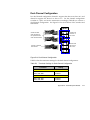
3.4
Front Panel Board
The system includes a front panel controller board that serves as an interface to
the internal system components and relays external messages through the LED
indicators and the LCD display screen.
Refer to Chapter 1 for details about front panel board functions.
Figure 3-8 shows the front panel board connections with the internal components.
Power
Subsystem
System Board
J11
LCD Module
BP
(L)
BP
(R)
Figure 3-8 Front Panel Board Connections
Chapter 3 - System Housing 3-9
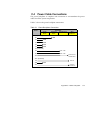
3.5
Power Subsystem
This section gives a brief description of the power subsystem. Refer to Appendix
C for a detailed discussion.
The power subsystem consists of a power backplane, swappable power supply
modules, and an optional uninterruptible power supply (UPS) module held in
place by a metal rack enclosure. The backplane and the rack allow installation of
up to three 400-watt power supply modules in a load-sharing (across two),
redundant configuration.
3.6
ESD Precautions
Always observe the following ESD (electrostatic discharge) precautions before
installing any system component:
1.
Do not remove any system component from its packaging unless you are
ready to install it.
2.
Wear a wrist grounding strap before handling electronic components. Wrist
grounding straps are available at most electronic component stores.
DO NOT attempt the procedures in the
following sections unless you are confident of
your capability to perform them. Otherwise,
ask a service technician for assistance.
3-10 AcerAltos 19000 User’s Guide
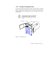
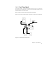
3.7
Installing Additional Devices
The housing supports one 3.5-inch and three 5.25-inch devices. The empty drive
bays on the upper front panel allow you to install additional devices such as a
Digital Audio Tape (DAT) drive or another hard disk drive.
Your basic system ships standard with a CDROM drive and a 3.5-inch diskette drive
already installed.
Follow these steps to install a device:
1.
Remove the upper front panel cover and the upper front panel door. See
Figures 3-5 and 3-6 for illustrations.
2.
Attach the drive guides on the sides of the external device that you wish to
install.
Figure 3-9 Attaching the Drive Guides
If you are installing a SCSI device, set its ID
and terminator before installing it into the
drive bay.
Chapter 3 - System Housing 3-11
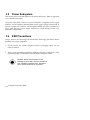
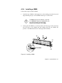
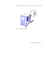
3.
Insert the drive into the bay.
Figure 3-10 Installing an Additional Externally-Accessible Device
4.
Connect the drive power and signal cables.
5.
Remove the plastic cover from the front panel before reinstalling it.
3-12 AcerAltos 19000 User’s Guide
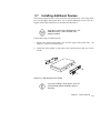
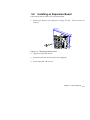
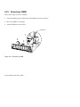
3.8
Installing an Expansion Board
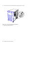
Follow these steps to install a PCI expansion board:
1.
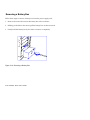
Remove the bracket cover opposite an empty PCI slot. Save the screw for
later use.
Figure 3-11 Removing a Bracket Cover
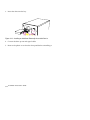
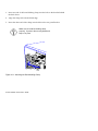
2.
Align the board with the slot.
3.
Insert the board into the slot until it fits completely.
4.
Secure the board with a screw.
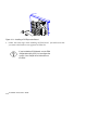
Chapter 3 - System Housing 3-13
Figure 3-12 Installing a PCI Expansion Board
5.
Follow the same steps when installing an EISA board. Just make sure that
you remove the bracket cover opposite an EISA slot.
If you installed an EISA board, run the EISA
configuration utility (ECU) to reconfigure the
system. See Chapter 6 for information on
the ECU.
3-14 AcerAltos 19000 User’s Guide
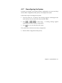
Chapter 4
4.1
System Board
Major Components
The system board carries all the major system components including the two
sockets for the Intel Pentium Pro processors. Figure 4-1 shows the major
components on the system board.
Chapter 4 - System Board 4-1
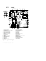
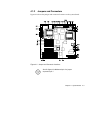
4.1.1
Layout
24
28 27 28
1
29
30
31
1
25
26
23
22
2
21
20
3
19
18
PC1
4
PC2
17
5
6
PC3
PC4
7
8
PC5
9
PC6
E1
16
10
E2
11
E3
15
1.
2.
3.
4.
5.
6.
7.
8.
9.
10.
11.
12.
13.
14.
15.
16.
14
Power connectors
VRM connector 1
Pentium Pro processor socket 1
Fan connector 5 (Fan5)
Fan connector 1 (Fan1)
Fan connector 2 (Fan2)
Fan connector 3 (Fan3)
Buzzer
Real-time clock
BIOS
Narrow SCSI interface
Wide SCSI interface
VGA RAM
EISA slots
PCI slots
Keyboard controller
Figure 4-1 System Board Layout
4-2 AcerAltos 19000 User’s Guide
12
13
17.
18.
19.
20.
21.
22.
23.
24.
25.
26.
27.
28.
29.
30.
31.
CPU voltage regulator
Fan connector 4 (Fan4)
VRM connector 2
Parallel port
Video port
Serial port 1
Serial port 2
Fan connector 6 (Fan6)
Keyboard port
Mouse port
Pentium Pro processor socket 2
RDM connectors
Memory board slot
Diskette drive connector
IDE connector
4.1.2
Jumpers and Connectors
Figure 4-2 shows the jumper and connector locations on the system board.
Figure 4-2 Jumper and Connector Locations
On this figure, the blackened pin of a jumper
represents pin 1.
Chapter 4 - System Board 4-3
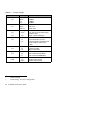
Table 4-1
Jumper Settings
Jumper
Oscillator Freq.
J12
SCSI Feature
J13
ITP Boundary Scan
J14
J15
SCSI Termination
J16
Password Security
J18
BIOS Logo
J19
Sound Output
J1501
*
**
Setting
Function
Open
1-2
2-3*
50 MHz
60 MHz
66 MHz
Open
Closed*
Not Used
Wide SCSI
Open**
2-3**
J14 and J15 are for CPU testing
purposes only.
Note: Do not reconfigure.
1-2
2-3*
SCSI terminator set to On
SCSI terminator switchable to On
or Off using the SCSI Setup
Utility
1-2
2-3*
Check password
Bypass password
1-2*
2-3
For models with Acer BIOS
For models with OEM BIOS
1-2*
Open
Enable buzzer output
Disable buzzer output
Default setting
Fixed setting. Not user-configurable.
4-4 AcerAltos 19000 User’s Guide
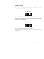
Voltage ID Settings
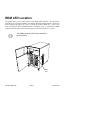
Figure 4-3 shows the settings of jumpers J2, J3, J4, and J5 to set CPU1 VRM
connector (J1) to 3.3V at 200 MHz.
J2
J3
J4
J5
Figure 4-3 VRM Settings for CPU1 (3.3V for 200 MHz)
Figure 4-4 shows the settings of jumpers J7, J8, J9, and J10 to set CPU2 VRM
connector (J6) to 3.3V at 200 MHz.
J7
J8
J9 J10
Figure 4-4 VRM Settings for CPU2 (3.3V for 200 MHz)
Table 4-2 lists the voltage identification (VID) code indicated by four binaryweighted inputs.
Chapter 4 - System Board 4-5
Table 4-2
Voltage Identification Codes
Pentium Pro Pins
Vccp
VID3
VID2
VID1
VID0
(VDC)
1
1
1
1
No CPU
1
1
1
0
2.1
1
1
0
1
2.2
1
1
0
0
2.3
1
0
1
1
2.4
1
0
1
0
2.5
1
0
0
1
2.6
1
0
0
0
2.7
0
1
1
1
2.8
0
1
1
0
2.9
0
1
0
1
3.0
0
1
0
0
3.1
0
0
1
1
3.2
0
0
1
0
3.3
0
0
0
1
3.4
0
0
0
0
3.5
0 = Processor pin connected to Vss
1 = Open
DO NOT change the settings of the voltage
ID jumpers unless you are qualified to do so.
Ask a technician if you need help when
configuring these jumpers.
4-6 AcerAltos 19000 User’s Guide
Table 4-3
Connector Functions
Connector
Function
CN1
3-pin power connector
CN2
10-pin power connector
CN3
10-pin power connector
CN4
14-pin power connector
CN5
RDM connector
CN6
RDM connector
CN7
Backplane LED connector
CN8
12-pin power connector
CN9
Front panel connector for twin-tower housing
CN10
Diskette drive connector
CN11
PS/2 keyboard/mouse connector
CN12
IDE hard disk connector
CN13
Serial port connector
CN14
Parallel port/VGA port connector
CN16
Hard disk LED connector
CN17
Reset/RDM cable connector
J1
VRM connector 1 (for CPU 1)
J6
VRM connector 2 (for CPU 2)
J17
50-pin narrow SCSI connector
J20
68-pin wide SCSI connector
Figure 4-5 shows the CN15 default setting indicating the clock frequency ratio of
3. Ask a qualified technician when changing the clock frequency ratio.
Figure 4-5 Clock Frequency Ratio Setting (CN15)
Chapter 4 - System Board 4-7
4.1.3
Installing a Pentium Pro Processor
The basic system includes an Intel Pentium Pro processor installed in CPU
socket 1. A second zero-insertion force (ZIF) CPU socket comes with the board
for a dual-processor configuration.
Follow these steps to install a Pentium Pro processor:
1.
Check that the heat sink side locks are unlocked.
2.
Attach the heat sink by sliding its rails along the longer sides of the
rectangular Pentium Pro processor. Make sure that the heat sink completely
covers the processor.
3.
Hold the CPU and the heat sink firmly together then slide the locks on the
sides of the heat sink to secure the CPU.
STEP 1
STEP 2
STEP 3
Figure 4-6 Attaching the Heat Sink to the CPU
4-8 AcerAltos 19000 User’s Guide
4.
Lift up the CPU socket lever.
5.
Look at the underside of the CPU and note the area where the pins are denser
or closely embedded. Gently insert the CPU pins into the socket, matching
the denser pins with the denser holes on the socket.
Be careful not to bend any pins.
6.
Push down the socket lever.
7.
Connect the CPU fan cable to connector Fan 6 (for CPU 2) on the system
board.
STEP 4
Denser Holes
STEP 6
STEP 5
Denser Pins
STEP 7
Fan Cable
Figure 4-7 Installing a Pentium Pro Processor
Chapter 4 - System Board 4-9
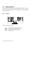
4.2
Memory Board
The memory board comes already installed with the basic system. A total of
eight memory banks composed of 16 72-pin SIMM sockets reside on the board.
The sockets accept 8-MB, 16-MB, and 32-MB SIMMs for a maximum 512 MB
memory configuration.
4.2.1
Layout
Figure 4-8 Memory Board Layout
When installing or removing memory, first
take out the memory board and place it on a
flat surface. Re-install the board with
sockets facing up.
4-10 AcerAltos 19000 User’s Guide
4.2.2
Rules for Adding Memory
Adhere to the following rules when you add system memory.
•
Always install SIMMs from bank 0.
consecutively.
•
Always install SIMMs in pairs to fill up a bank. For example, for a total
memory of 32 MB, install two 16 MB SIMMs in a bank; you cannot use a 32
MB SIMM alone for a 32 MB memory configuration.
•
Use only fast-page mode parity 60 nanosecond SIMMs.
•
Install SIMMs of the same capacity in a bank. For example, do not mix an 8
MB SIMM with a 16 MB SIMM.
•
Each time you change your system’s memory configuration, you must run
Setup and the EISA Configuration Utility (ECU) to reconfigure the system.
You should use the memory banks
When removing memory, run the ECU and
change memory size before physically
removing the memory; otherwise, the system
may become inoperable.
Chapter 4 - System Board 4-11
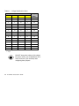
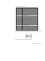
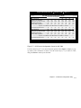
4.2.3
Memory Configurations
Table 4-4
Bank 0
Memory Configurations
Bank 1
Bank 2
Bank 3
Bank 4
Bank 5
Bank 6
Bank 7
16MB*2
Total
Memory
32 MB
16MB*2
16MB*2
16MB*2
16MB*2
16MB*2
16MB*2
64 MB
16MB*2
16MB*2
16MB*2
16MB*2
128 MB
16MB*2
16MB*2
16MB*2
16MB*2
32MB*2
256 MB
64 MB
32MB*2
32MB*2
128 MB
32MB*2
32MB*2
32MB*2
32MB*2
32MB*2
32MB*2
32MB*2
32MB*2
256 MB
32MB*2
4-12 AcerAltos 19000 User’s Guide
32MB*2
32MB*2
32MB*2
512 MB
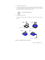
4.2.4
Installing a SIMM
Follow these steps to install a SIMM:
1.
Carefully slip a SIMM at a 45° angle into a socket making sure that the curved
edge indicating the pin 1 of the SIMM matches pin 1 of the socket.
A SIMM fits only in one direction. If you slip
in a SIMM but it does not completely fit, you
may have inserted it the wrong way.
Reverse the orientation of the SIMM.
2.
Gently push the SIMM to a vertical position until the pegs of the socket slip
into the holes on the SIMM, and the holding clips lock the SIMM into
position. The SIMM should be at a 90° angle when installed.
1
2
Peg
Pin 1 Indicator
(curved edge)
Hole
Figure 4-9 Installing a SIMM
Chapter 4 - System Board 4-13
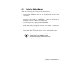
4.2.5
Removing a SIMM
Follow these steps to remove a SIMM:
1.
Press the holding clips on both sides of the SIMM outward to release it.
2.
Move the SIMM to a 45° angle.
3.
Pull the SIMM out of the socket.
Holding Clip
1
3
2
Figure 4-10 Removing a SIMM
4-14 AcerAltos 19000 User’s Guide
4.2.6
Installing the Memory Board
Follow these steps to install the memory board:
1.
Align the memory board with the memory board slot on the system board.
Install the memory board with the component
side up.
2.
Insert the board into the slot until it fits into place. Be sure the board is fully
seated in the slot.
Figure 4-11 Inserting the Memory Board
Chapter 4 - System Board 4-15
3.
Insert one end of the board holding clamp into the hole on the bracket behind
the disk drives.
4.
Align the clamp rail with the board edge.
5.
Insert the other end of the clamp into the hole on the rear panel bracket.
Make sure to install the holding clamp
properly. It protects the memory board and
keeps it in place
Figure 4-12 Attaching the Board Holding Clamp
4-16 AcerAltos 19000 User’s Guide
4.2.7
Reconfiguring the System
Each time you change your system’s memory configuration, you must run Setup
and the EISA Configuration Utility (ECU) to reconfigure the system.
Follow these steps to reconfigure the system:
1.
Turn the system on. A memory error message appears, indicating that the
total memory does not match the value stored in CMOS.
2.
+
+
to enter Setup. A warning message appears
Press
indicating an incorrect memory configuration.
3.
Press
twice to exit and reboot the system.
The system boots with the new memory configuration.
4.
Run the EISA Configuration Utility (ECU).
Chapter 4 - System Board 4-17
4-18 AcerAltos 19000 User’s Guide
Chapter 5
BIOS Utility
The system is already configured by the manufacturer or the dealer. There is no
need to run Setup when starting the computer unless you get a configuration
error.
The Setup program loads configuration values into the battery-backed nonvolatile
memory called CMOS RAM. This memory area is not part of the system RAM.
If you repeatedly receive Run Setup
messages, the battery may be bad. In this
case, the system cannot retain the
configuration values in CMOS. Ask a
qualified technician for assistance
•
Diskette drive type The standard type is 3.5-inch 1.44 MB diskette drive.
Chapter 5 - BIOS Utility 5-1
5.1
Entering Setup
To enter Setup, press the key combination
+
+
.
while the
You must press
+
+
system is booting. This key combination
does not work during any other time.
The BIOS Utility main menu then appears:
BIOS Utility
Basic System Configuration
Advanced System Configuration
System Security
PCI System Configuration
Non-PnP ISA Card Configuration
RDM
Load Setup Default Settings
↑↓ = Move Highlight Bar,
←
= Select,
Esc = Exit and Reboot
The parameters on the screens show default
values. These values may not be the same
as those in your system.
The grayed items (denoted with asterisks) on
the screens have fixed settings and are not
user-configurable.
5-2 AcerAltos 19000 User’s Guide
5.2
Basic System Configuration
Select Basic System Configuration to input configuration values such as date,
time, and disk types.
The following screen shows the Basic System Configuration menu.
Basic System Configuration
Date .....................
Time .....................
Diskette Drive A .........
Diskette Drive B .........
[MM/DD/YY]
[HH:MM:SS]
[1.44-MB
[None]
3.5-inch]
Cylinder
Hard Disk 0
Hard Disk 1
(xxx MB) ..... [None]
(xxx MB) ..... [None]
*Base Memory .............
*Extended Memory .........
*Total Memory ............
*Math Coprocessor ........
*Video Display ...........
↑↓ = Move Highlight Bar,
PgDn/PgUp = Move Screen,
Page 1/2
Head
xx
xx
[ 640] KB
[ xxxx] KB
[ xxxx] KB
[
Installed
[VGA/EGA]
xx
xx
Sector
xx
xx
]
→ ← = Change Setting
Esc = Exit
The command line at the bottom of the menu tells you how to highlight items,
change settings, and move from one screen to another.
Press
or
on the cursor-edit keypad to highlight the desired parameter.
Press
or
to select the desired option for a parameter.
Press
to move to the next page or
Press
to exit the configuration menu.
to return to the previous page.
The following screen shows page 2 of the Basic System Configuration menu.
Chapter 5 - BIOS Utility 5-3
Basic System Configuration
Communication Settings
Baud Rate .....................
Parity ........................
Stop Bits .....................
Data Length ...................
Page 2/2
[9600] BPS
[None]
[1] Bits
[8] Bits
Enhanced IDE Features
Hard Disk Size > 504MB ........ [Disabled]
Hard Disk Block Mode .......... [Disabled ]
Large Memory Support Mode .........
Num Lock After Boot ..............
Memory Test ......................
Auto Configuration Mode ...........
Fast Boot Mode ...................
↑↓ = Move Highlight Bar,
PgDn/PgUp = Move Screen,
[ Normal ]
[Enabled ]
[Disabled]
[Disabled]
[Disabled]
→ ← = Change Setting
Esc = Exit
The following sections explain the different parameters and their settings.
5.2.1 Date and Time
The real-time clock keeps the system date and time. After setting the date and
time, you need not enter them every time you turn on the system. As long as the
internal battery remains good (approximately seven years) and connected, the
clock continues to keep the date and time accurately even when the power is off.
5-4 AcerAltos 19000 User’s Guide
Date
Highlight the items on the date parameter and press
following the month-day-year format.
or
to set the date
or
to set the time
Valid values for month, day, and year are:
•
Month
1 to 12
•
Day
1 to 31
•
Year
00 to 99
Time
Highlight the items on the time parameter and press
following the hour-minute-second format.
Valid values for hour, minute, and second are:
•
Hour
00 to 23
•
Minute
00 to 59
•
Second
00 to 59
Chapter 5 - BIOS Utility 5-5
5.2.2 Diskette Drives
To enter the configuration value for the first diskette drive (drive A), highlight the
or
key to view the options and select
Diskette Drive A parameter. Press
the appropriate value.
Possible settings for the Diskette Drive parameters:
•
[
•
[360
KB,
5.25-inch]
•
[1.2
MB,
5.25-inch]
•
[720
KB,
3.5-inch]
•
[1.44 MB,
3.5-inch]
•
[2.88 MB,
3.5-inch]
None
]
Follow the same procedure for Diskette Drive B. Choose None if you do not have
a second diskette drive.
5-6 AcerAltos 19000 User’s Guide
5.2.3 Hard Disk Drives
Move the highlight bar to the hard disk 0 parameter to configure the first hard
or
to display the hard disk types with their
disk (drive C). Press
respective values. Select the type that corresponds to your hard disk drive.
Follow the same procedure for the other hard disks, if any. Choose None if you
do not have other drives. The default setting is None.
When booting from a SCSI fixed disk installation, have both of these options
set to None.
The following sections, “Selecting the Auto
Option” and “Selecting the User Option, “
describe functions used for IDE drives only.
Selecting the “Auto” Option
If you do not know the exact type of your IDE fixed disk, select the option Auto.
During the power-on self-test (POST), when the system performs self-testing and
self-initialization before loading the operating system and applications, the BIOS
utility automatically determines your hard disk type. You can see the drive type
and its values when you enter the BIOS Utility.
Cylinder Head Sector
Hard Disk 0 (xx MB) ... [Auto]
xx
xx
xx
If desired, you can save the values under the option User.
Cylinder Head Sector
Hard Disk 0 (xx MB) ... [User]
xx
xx
xx
Chapter 5 - BIOS Utility 5-7
The next time you boot the system, the BIOS utility does not have to autoconfigure your hard disk as it detects the saved disk information during POST.
We recommend that you copy the IDE disk
drive values and keep them in a safe place in
case you have to reconfigure the disk in the
future.
Follow the same procedure to auto-configure other IDE hard disks.
Selecting the “User” Option
There are cases when you cannot use the option Auto, instead you have to select
User. Choose the User option when you have installed an IDE fixed disk that
was previously formatted but does not use the disk native parameters or
structure, that is, the disk type may be in the hard disk types list but the number
of cylinders, heads, and sectors differ.
Follow these steps to configure a hard disk with the User option:
1.
Highlight an hard disk parameter.
2.
Select the option User and press
3.
Type in the number of cylinders, heads, and sectors of the drive under the
appropriate columns.
.
Be sure to have the correct hard disk
information beforehand.
4.
Choose Yes when asked if you want to save CMOS data.
5-8 AcerAltos 19000 User’s Guide
5.2.4 System Memory
The system automatically detects the total amount of onboard memory during the
POST and sets the memory parameters accordingly. If you install additional
memory, the system automatically adjusts the Total Memory parameter to
display the new memory size (refer to section 4.2.7). You must enter CMOS
Setup and exit. A message that the memory configuration has changed is
displayed. When changing your system’s memory configuration, be sure to run
the ECU to add in the changes.
5.2.5 Math Coprocessor
The CPU includes a math coprocessor so this parameter shows Installed by
default.
5.2.6 Video Display
The video display is the monitor on which the operating system prompt appears
when you boot the system. The system automatically detects the video mode of
your primary display and sets the configuration value accordingly. Values for
this parameter are:
•
[Monochrome]
•
[CGA 40 columns x 25 rows]
•
[CGA 80 columns x 25 rows]
•
[VGA/EGA]
Chapter 5 - BIOS Utility 5-9
5.2.7 Communication Settings
The Communication Settings parameters allow you to set the baud rate, parity,
stop bit, and data length for the first serial port. The values for this parameter
are:
•
Baud rate
:
110 to 9600 bits per second (bps)
•
Parity
:
odd, even, or none
•
Stop bit
:
1 or 2 stop bits
•
Data length :
7- or 8-bit data word
The baud rate maximum value 9600 bps
applies only to POST under UNIX
environment. The system I/O chipset
SMC 37C665 supports up to 115.2K bps.
5-10 AcerAltos 19000 User’s Guide
5.2.8 Enhanced IDE Features
Hard Disk Size > 504 MB
This enhanced IDE feature works only under DOS and Windows 3.x
environments. If enabled, it allows you to use a hard disk with a capacity of more
than 504 MB. This is made possible through the Logical Block Address (LBA)
mode translation. Other operating systems require this parameter to be set to
Disabled.
To prevent data loss, set this parameter set to Enabled if you are using a hard
disk with more than 504 MB capacity that was previously configured through
LBA mode. If you use a hard disk configured through cylinder-head-sector
(CHS) mode, set this item to Disabled.
Hard Disk Block Mode
This function enhances disk performance depending on the hard disk in use. If
you set this parameter to Enabled, it allows data transfer in block (multiple
sectors) by increasing the data transfer rate to 256 bytes per cycle. If your system
does not boot after enabling this parameter, change the setting to Disabled. This
parameter is normally set to Disabled.
5.2.9 Large Memory Support Mode
This parameter allows the system to support extended memory higher than 64
MB. Set this parameter to Advanced if you are working under Windows NT
environment and the system memory size is greater than or equal to 64 MB.
Otherwise, set it to Normal. The default setting is Normal.
5.2.10 Num Lock After Boot
This parameter allows you to activate the Num Lock function upon booting. The
default setting is Enabled.
Chapter 5 - BIOS Utility 5-11
5.2.11 Memory Test
When set to Enabled, this parameter allows the system to perform a RAM test
during the POST routine. When set to Disabled, the system detects only the
memory size and bypasses the test routine. The default setting is Disabled.
This item is fixed to Disabled and is not user-configurable if you enabled the
Auto Configuration Mode and the Fast Boot Mode parameters on page 2 of the
Basic System Configuration menu. See section 5.2.12 and 5.2.13.
5.2.12 Auto Configuration Mode
When enabled, this parameter automatically sets the system configuration values
to their optimized settings. At the same time, it causes the Memory Test
parameter to be fixed to Disabled and the shadow RAM regions for system and
video BIOS to Enabled. See sections 5.2.11 and 5.3.1.
This parameter is Disabled by default.
5.2.13 Fast Boot Mode
When enabled, this parameter allows the system to boot faster by skipping some
POST routines. It bypasses memory test, enables Shadow RAM, and enables
primary- and second-level cache. This parameter is Disabled by default.
When set to Enabled, this parameter causes the Memory Test parameter to be
fixed to Disabled and the shadow RAM regions for system and video BIOS to
Enabled. See section 5.2.11 and 5.3.1.
5-12 AcerAltos 19000 User’s Guide
5.3
Advanced System Configuration
The Advanced System Configuration option allows you to configure the
advanced system memory functions.
Do not change any settings in the Advanced
Configuration if you are not a qualified
technician to avoid damaging system.
The following screen shows page one of the Advanced System Configuration
parameters.
Advanced System Configuration
Shadow RAM
*E0000h *C0000h C8000h CC000h D0000h D4000h D8000h DC000h -
FFFFFh (System BIOS) ...
C7FFFh (Video BIOS) .....
CBFFFh .................
CFFFFh .................
D3FFFh ..................
D7FFFh .................
DBFFFh .................
DFFFFh .................
Page 1/1
[Enabled ]
[Enabled ]
[Disabled]
[Disabled]
[Disabled]
[Disabled]
[Disabled]
[Disabled]
L1 & L2 Cache (CPU Cache) ........... [Enabled ]
Cache Scheme .................... [ Write Back ]
Video Buffer Memory Type
....... [Non-cacheable]
Memory at 15MB-16MB Reserved for ..... [
↑↓ = Move Highlight Bar,
PgDn/PgUp = Move Screen,
System
] Use
→ ← = Change Setting
Esc = Exit
The grayed parameters (denoted with
asterisks) are not user-configurable.
Chapter 5 - BIOS Utility 5-13
5.3.1 Shadow RAM
The system reserves 384 KB of random access memory (RAM) for the shadow
RAM function. This parameter has eight range addresses. When you set these
addresses to Enabled, the system BIOS, video BIOS, and I/O ROM functions run
directly from the shadow RAM for faster operation. When you set them to
Disabled, the functions run normally from ROM.
The address range E0000h - FFFFFh is for shadowing the system BIOS. This item
is always set to Enabled and is not user-configurable. The address range
C0000h - C7FFFh is for shadowing the video BIOS. This item is fixed to Enabled
and is not user-configurable if the Auto Configuration Mode and the Fast Boot
Mode parameters on page 2 of the Basic System Configuration menu are enabled.
Otherwise, you can choose to disable this item..
The remaining address ranges are for I/O ROM functions.
5.3.2 L1 and L2 Cache (CPU Cache)
This parameter enables or disables the first-level and second-level cache
integrated in the Pentium Pro processor. This item is fixed to Enabled and is not
user-configurable if you enabled the Auto configuration Mode and Fast Boot
Mode parameters on page 2 of the Basic System Configuration menu.
Cache Scheme
This parameter sets the cache to Write-through or Write-back modes. Writeback updates the cache but not the memory when there is a write instruction. It
updates the memory only when there is cache miss or an inconsistency between
the cache and the memory. Write-through updates both the cache and the
memory whenever there is a write instruction. The default setting is Write-back.
5-14 AcerAltos 19000 User’s Guide
Video Buffer Memory Type
This parameter allows you to enable or disable the video cache buffer feature.
When you set this parameter to USWC, the uncacheable, speculative writecombining (USWC) buffer in the CPU temporarily stores video write data. When
the USWC buffer is full, the CPU eventually writes the data to the memory
address A0000h~BFFFFh reserved for video data. The default setting, Noncacheable, disables this feature.
5.3.3 Memory at 15MB-16MB
To prevent memory address conflicts between the system and expansion boards,
reserve this memory range for the use of either the system or an expansion board.
Before setting this parameter, check your add-on card manual to determine if
your add-on card needs this memory space. If not, leave this parameter at the
default setting of System Use.
Chapter 5 - BIOS Utility 5-15
5.4
System Security Setup
The Setup program has a number of security features to prevent unauthorized
access to the system and its data.
Enter the Setup program and select System Security.
appears:
System Security
Disk Drive Control
Diskette Drive ................. [
Normal
Hard Disk Drive ................ [
Normal
System Boot Drive .............. [Drive A then C]
Onboard Communication Ports
Serial Port 1 Base Address .....
Serial Port 2 Base Address .....
Parallel Port Base Address .....
Operation Mode ..............
ECP DMA Channel ...........
The following screen
Page 1/1
]
]
[
3F8h
]
[
2F8h
]
[3BC (IRQ 7)]
[Enhanced Parallel Port (EPP)] Mode
[-]
Onboard PS/2 Mouse (IRQ12) ... [Enabled ]
Setup Password ................... [
Power On Password ................ [
↑↓ = Move Highlight Bar,
PgDn/PgUp = Move Screen,
None
None
]
]
→ ← = Change Setting
Esc = Exit
5.4.1 Disk Drive Control
The disk drive control features allow you to enable or disable the read/write
functions of a disk drive. These features can also control the diskette drive or the
hard disk drive boot function to prevent loading operating systems or other
programs from a certain drive while the other drives are operational.
Table 5-1 lists the drive control settings and their corresponding functions.
5-16 AcerAltos 19000 User’s Guide
Table 5-1
Drive Control Settings
Diskette Drive
Setting
Description
Normal
Diskette drive functions normally
Write Protect All Sectors
Disables the write function on all sectors
Write Protect Boot Sector
Disables the write function only on the
boot sector
Disabled
Disables all diskette functions
Hard Disk Drive
Setting
Description
Normal
Hard disk drive functions normally
Write Protect All Sectors
Disables the write function on all sectors
Write Protect Boot Sector
Disables the write function only on the
boot sector
Disabled
Disables all hard disk functions
System Boot Drive
Setting
Description
Drive A then C
The system checks drive A first. If there
is a diskette in the drive, the system
boots from drive A. Otherwise, it boots
from drive C.
Drive C then A
The system checks drive C first. If there
is a hard disk (drive C) installed, the
system boots from drive C. Otherwise,
it boots from drive A.
C:
The system always boots from drive C.
A:
The system always boots from drive A.
Chapter 5 - BIOS Utility 5-17
5.4.2 Onboard Communication Ports
Serial Port 1 Base Address
This parameter enables serial port 1 as COM1 and sets its base address.
Table 5-2
Serial Port 1 Settings
Setting
Description
Serial 1 (3F8h)
COM1 with address 3F8h
2F8h
COM2 with address 2F8h
3E8h
COM3 with address 3E8h
2E8h
COM4 with address 2E8h
Disabled
Disables serial port 1
Serial Port 2 Base Address
This parameter enables serial port 2 as COM2 and sets its base address.
Table 5-3
Serial Port 2 Settings
Setting
Description
Serial 2 (2F8h)
COM2 with address 2F8h
3F8h
COM1 with address 3F8h
2E8h
COM4 with address 2E8h
3E8h
COM3 with address 3E8h
Disabled
Disables serial port 2
5-18 AcerAltos 19000 User’s Guide
Parallel Port Base Address
The system has one parallel port. Table 5-4 lists the options for selecting the
parallel port address. You also have the option to disable the parallel port.
Table 5-4
Parallel Port Settings
Setting
Function
3BCh (IRQ 7)
Corresponds to the parallel port with
address 3BCh
378h (IRQ 7)
Corresponds to the parallel port with
address 378h
278h (IRQ 5)
Corresponds to the parallel port with
address 278h
Disabled
Disables the parallel port
To deactivate the parallel port, select the Disabled option. If you install an addon card that has a parallel port whose address conflicts with the parallel port
onboard, the system automatically disables the onboard functions.
Check the parallel port address on the add-on card and change the address to one
that does not conflict. The default setting is 3BCh.
Chapter 5 - BIOS Utility 5-19
Operation Mode
This item allows you to set the operation mode of the parallel port. Table 5-5 lists
the different operation modes. The default setting is EPP.
Table 5-5
Parallel Port Operation Mode Settings
Setting
Function
Standard Parallel Port (SPP)
Allows normal speed one-way
operation
Standard and Bidirectional
Allows normal speed operation in
a two-way mode
Enhanced Parallel Port (EPP)
Allows bidirectional parallel port
operation at maximum speed
Extended Capabilities Port
(ECP)
Allows parallel port to operate in
bidirectional mode and at a speed
higher than the maximum data
transfer rate
ECP DMA Channel
This item becomes active only if you select Extended Capabilities Port (ECP) for
the operation mode parameter. It allows you to select DMA channel 1 or DMA
channel 3 depending on the available system resource.
5.4.3 Onboard PS/2 Mouse (IRQ12)
This parameter enables or disables the onboard PS/2 mouse. When set to
Enabled, it allows you to use the onboard PS/2 mouse assigned with IRQ12.
When set to Disabled, it deactivates the mouse and frees IRQ12 for the use of
other devices. The default setting is Enabled.
5-20 AcerAltos 19000 User’s Guide
5.4.4 Setup Password
The Setup Password prevents unauthorized access to the BIOS utility.
Set system board jumper JP18 to pins 1-2 to
enable the password function.
Setting a Password
1.
Highlight the Setup Password parameter and press the left- or right-arrow
key. The password prompt appears:
2.
Type a password. The password may consist of up to seven characters.
Exercise caution when typing your password
because the characters do not appear on the
screen.
3.
Press
entry.
. A prompt asks you to retype the password to verify your first
4.
Retype the password then press
.
After setting the password, the system automatically sets the Setup Password
parameter to Present. The next time you want to enter the BIOS utility, you must
key-in your Setup password.
Chapter 5 - BIOS Utility 5-21
If You Forget the Password
If you forget your password, you must return the configuration values stored in
CMOS to their default values. Should this happen, call your dealer for assistance.
5.4.5 Power On Password
The Power On Password secures your system against unauthorized use. Once
you set this password, you have to type it whenever you boot the system. To set
this password, follow the same procedure as in setting the Setup password.
5-22 AcerAltos 19000 User’s Guide
5.5
PCI System Configuration
The PCI System Configuration allows you to specify the settings for your PCI
devices.
PCI System Configuration
PCI IRQ Setting
*PCI
*PCI
*PCI
*PCI
*PCI
*PCI
Slot
Slot
Slot
Slot
Slot
Slot
1
2
3
4
5
6
........... [ Auto ]
INTA
INTB
...........
[--]
[--]
...........
[--]
[--]
...........
[--]
[--]
...........
[--]
[--]
...........
[--]
[--]
...........
[--]
[--]
Page 1/1
VGA Palette Snoop
INTC
[--]
[--]
[--]
[--]
[--]
[--]
INTD
[--]
[--]
[--]
[--]
[--]
[--]
......... [Disabled]
Onboard SCSI .............. [Enabled]
Boot Device ........... [Enabled]
↑↓ = Move Highlight Bar,
PgDn/PgUp = Move Screen,
→ ← = Change Setting
Esc = Exit
5.5.1 PCI IRQ Setting
This parameter allows for Auto or Manual configuration of PCI devices. If you
use plug-and-play (PnP) devices, you can keep the default setting Auto. The
system then automatically configures the PnP devices. If your PCI device is not a
PnP, you can manually assign the interrupt for each device. Refer to your manual
for technical information about the PCI card.
Chapter 5 - BIOS Utility 5-23
PCI Slots
These parameters allow you to specify the appropriate interrupt for each of the
PCI devices. You can assign IRQ3, IRQ4, IRQ5, IRQ7, IRQ9, IRQ10, IRQ11,
IRQ12, or IRQ15 to the slots.
The IRQs that can be assigned to each PCI slot are listed below:
Slots 1-3
Can be assigned IRQ3, IRQ4, IRQ5, IRQ7, IRQ9, IRQ10,
IRQ11, IRQ12, or IRQ15
Slots 4-6
Can be assigned IRQ3, IRQ9, IRQ10, IRQ11, IRQ12, or
IRQ15
To avoid conflicts, make sure that the
interrupt you assign to the PCI slot is not
used by other devices, embedded or add-on.
Press
or
to move between fields. Press
or
to select options.
5.5.2 VGA Palette Snoop
PCI devices support a palette snooping technique that enables the device to
control access to their palette registers. Set this parameter to Enabled if you
install an additional video device in an EISA bus slot. Set this parameter to
Disabled if you don’t have an additional video device installed. The default
setting is Disabled.
5.5.3 Onboard SCSI
This parameter allows you to enable or disable the onboard SCSI controller. The
default setting is Enabled.
Boot Device
This parameter allows you to enable or disable the onboard SCSI boot priority.
Setting this item to Enabled allows the onboard SCSI device to be the first
priority boot device. The default setting is Enabled.
5-24 AcerAltos 19000 User’s Guide
5.6
Non-PnP ISA Card Configuration
The Non-PnP ISA Card Configuration parameters allow you to specify the
settings for cards without the plug-and-play (PnP) feature.
Non-PnP ISA Card Configuration
IRQ/DMA
IRQ 00 ... [---]*
IRQ 08 ...
IRQ 01 ... [---]*
IRQ 09 ...
IRQ 02 ... [---]*
IRQ 10 ...
IRQ 03 ... [No ]
IRQ 11 ...
IRQ 04 ... [No ]
IRQ 12 ...
IRQ 05 ... [No ]
IRQ 13 ...
IRQ 06 ... [---]*
IRQ 14 ...
IRQ 07 ... [No ]
IRQ 15 ...
Expansion ROM Region
C8000h - CBFFFh .... [No ]
CC000h - CFFFFh .... [No ]
D0000h - D3FFFh .... [No ]
↑↓ = Move Highlight Bar,
PgDn/PgUp = Move Screen,
[---]*
[No ]
[No ]
[No ]
[No ]
[---]*
[---]*
[No ]
DMA
DMA
DMA
DMA
DMA
DMA
DMA
DMA
Page 1/3
0
1
2
3
4
5
6
7
...
...
...
...
...
...
...
...
[No ]
[No ]
[---]*
[No ]
[---]*
[No ]
[No ]
[No ]
D4000h - D7FFFh .... [No ]
D8000h - DBFFFh .... [No ]
DC000h - DFFFFH .... [No ]
→ ← = Change Setting
Esc = Exit
The grayed items (denoted with asterisks)
have fixed settings and are not userconfigurable.
Chapter 5 - BIOS Utility 5-25
Non-PnP ISA Card Configuration
I/O Region
100h-10Fh ..
110h-11Fh ..
120h-12Fh ..
130h-13Fh ..
140h-14Fh ..
150h-15Fh ..
160h-16Fh ..
170h-17Fh ..
180h-18Fh ..
190h-19Fh ..
1A0h-1AFh ..
1B0h-1BFh ..
1C0h-1CFh ..
1D0h-1DFh ..
1E0h-1EFh ..
1F0h-1FFh ..
[No ]
[No ]
[No ]
[No ]
[No ]
[No ]
[No ]
[No ]
[No ]
[No ]
[No ]
[No ]
[No ]
[No ]
[No ]
[---]*
200h-20Fh
210h-21Fh
220h-22Fh
230h-23Fh
240h-24Fh
250h-25Fh
260h-26Fh
270h-27Fh
280h-28Fh
290h-29Fh
2A0h-2AFh
2B0h-2BFh
2C0h-2CFh
2D0h-2DFh
2E0h-2EFh
2F0h-2FFh
↑↓ = Move Highlight Bar,
PgDn/PgUp = Move Screen,
.
.
.
.
.
.
.
.
.
.
.
.
.
.
.
.
[No
[No
[No
[No
[No
[No
[No
[No
[No
[No
[No
[No
[No
[No
[No
[No
]
]
]
]
]
]
]
]
]
]
]
]
]
]
]
]
300h-30Fh .. [No
310h-31Fh .. [No
320h-32Fh .. [No
330h-33Fh .. [No
340h-34Fh .. [No
350h-35Fh .. [No
360h-36Fh .. [No
370h-37Fh .. [No
380h-38Fh .. [No
390h-39Fh .. [No
3A0h-3AFh .. [No
3B0h-3BFh .. [No
3C0h-3CFh .. [No
3D0h-3DFh .. [No
3E0h-3EFh .. [No
3F0h-3FFh .. [No
Local Memory Region
1MB - 2MB .............. [No]
2MB - 3MB .............. [No]
3MB - 4MB .............. [No]
4MB - 5MB .............. [No]
5MB - 6MB .............. [No]
6MB - 7MB .............. [No]
7MB - 8MB .............. [No]
8MB - 9MB .............. [No]
9MB - 10MB .............. [No]
10MB - 11MB .............. [No]
11MB - 12MB .............. [No]
12MB - 13MB .............. [No]
13MB - 14MB .............. [No]
15MB - 16MB .............. [No]
5-26 AcerAltos 19000 User’s Guide
]
]
]
]
]
]
]
]
]
]
]
]
]
]
]
]
→ ← = Change Setting
Esc = Exit
Non-PnP ISA Card Configuration
↑↓ = Move Highlight Bar,
PgDn/PgUp = Move Screen,
Page 2/3
→ ← = Change Setting
Esc = Exit
Page 3/3
Refer to your non-PnP ISA card manual
when setting the following parameters.
5.6.1 IRQ/DMA
This parameter allows you to assign specific IRQ and DMA channels to non-PnP
ISA cards. The system will not use such IRQ and DMA channels when it
automatically assigns channels to PnP cards.
5.6.2 Expansion ROM Region
This parameter specifies the memory regions available for add-on card use. It
allows you to manually assign specific regions to non-PnP cards so that the
system will not use those regions anymore when it automatically configures PnP
cards.
5.6.3 I/O Region
The items under this parameter allow you to reserve 16-byte memory address
ranges for non-PnP cards. When the system configures PnP cards, the address
ranges that you marked will not be used anymore.
You can assign memory addresses to non-PnP cards at random as long as you
cover the address range required by the card. For example, for a card that
requires 178h-188h address, you have to set regions 170h-17Fh and 180h-18Fh to
Yes.
5.6.4 Local Memory Region
The items under this parameter allow you to reserve areas in the local memory
region for non-PnP cards. When the system configures PnP cards, the memory
areas that you marked will not be used anymore.
Chapter 5 - BIOS Utility 5-27
5.7
Remote Device Manager (RDM)
The following screens show the Remote Device Manager Setup parameters. If
this feature has been implemented, refer to the RDM documentation for
information.
RDM
Page 1/2
RDM Mode Number .......................[Disabled]
↑↓ = Move Highlight Bar,
PgDn/PgUp = Move Screen,
→ ← = Change Setting
F1 = Help,
Esc = Exit
Remote Diagnostic Configuration
Page 2/2
RDM system critical paging no. ........[
]
RDM remote connection phone no. .......[
RDM remote connection password ........[
]
]
↑↓ = Move Highlight Bar,
PgDn/PgUp = Move Screen,
5-28 AcerAltos 19000 User’s Guide
→ ← = Change Setting
F1 = Help,
Esc = Exit
5.8
Load Setup Default Settings
Use this option to load the default settings for the optimized system
configuration. When you load the default settings, some of the parameters are
grayed-out with their fixed settings. These grayed parameters are not userconfigurable. If you want to change the settings of these items, disable the Fast
Boot Mode parameter in the Basic System Configuration menu.
The following dialog box appears when you select Load Setup Default Settings
from the main menu.
Load Setup Default Settings
Are you sure
[Yes]
[No]
Select [Yes] to load the default settings.
Some of the settings may be different after
loading defaults. Your system as it left the
factory used the defaults as specified in this
User’s Guide.
Chapter 5 - BIOS Utility 5-29
5.9
Leaving Setup
Examine the system configuration values. When you are satisfied that all the
values are correct, write them down. Store the recorded values in a safe place. In
the future, if the battery loses power or the CMOS chip is damaged, you will
know what values to enter when you rerun Setup.
to leave the system configuration setup. If there is any change in the
Press
BIOS utility functions, the following screen appears:
Do you want to save CMOS data?
[Yes]
[No]
Use the arrow keys to select your response. Select Yes to store the new data in
.
CMOS. Select No to retain the old configuration values. Press
5-30 AcerAltos 19000 User’s Guide
Chapter 6
Utilities
This chapter describes the following utilities:
•
Acer Server Manager (ASM) Pro
•
Remote Device Manager (RDM)
•
EISA Configuration Utility (ECU)
6.1
Acer Server Manager (ASM) Pro
Acer Server Manager (ASM) Pro is a server management tool based on the Simple
Network Management Protocol (SNMP). It detects server problems related to
CPU thermal conditions, performs 5V/3.3V detection, and indicates PCI bus
utilization.
This feature is designed primarily for server supervisors and management
information system (MIS) personnel to help them detect errors or potential
trouble spots in their network servers through a single management station.
ASM Pro consists of two major parts:
•
ASM−Station - a Windows-based monitoring station that communicates with
the ASM−Agents.
•
ASM−Agent(s) - the individual servers managed by the ASM−Station.
If this feature has been implemented, refer to the Acer Server Manager (ASM) Pro
User’s Guide for information.
Chapter 6 - Utilities 6-1
6.2
Remote Device Manager (RDM)
Remote Device Manager (RDM) is a network management tool that utilizes
modems and telephone lines to control a host of servers from a remote station.
It monitors and analyzes the server condition, updates the BIOS settings if
necessary, or reboots the server in the event of failure and quickly returns it to
normal operation.
This capability to execute the RDM program from a remote site bridges the
distance barrier in fixing server problems and reduces wasted time due to system
failure.
If this feature has been implemented, refer to the RDM documentation for
information.
6-2 AcerAltos 19000 User’s Guide
6.3
EISA Configuration Utility (ECU)
The EISA Configuration Utility (ECU) is a program that allows you to easily
configure your EISA computer. Use this utility when you set up your EISA
computer for the first time or any time you change your configuration by adding
or removing an EISA or ISA board or memory. The program stores the
configuration information in the computer’s nonvolatile memory where it is
available whenever you use your computer.
Functions
The ECU does the following:
•
Configures memory and main board options.
•
Supports EISA and ISA boards, PCI devices, and plug-and-play ISA boards.
•
Automatically detects EISA boards, PCI devices, and plug-and-play ISA
boards installed in the computer.
•
Helps you configure ISA boards by providing the appropriate switch and
jumper settings, if the ISA board has a CFG file.
•
Notifies you if a conflict occurs during configuration.
•
Creates and maintains the System Configuration Information (SCI) file as a
backup for the computer’s nonvolatile memory.
•
Supports configuration (CFG) file extensions.
Chapter 6 - Utilities 6-3
Making Menu Selections
You can either use the keyboard or the mouse (if a mouse driver was loaded) to
make menu selections in the EISA Configuration Utility program.
Using the Keyboard
Table 6-1
Keyboard Function Keys
Key
Function
Tab or y
Moves the cursor to the next field
j + Tab or w
w or y
e
^
{, }, w or y
g
d
b+g
b+d
Moves the cursor to the previous field
Moves the cursor between items within a list
Selects an item
Cancels the most recent action
Scrolls a screen
Moves the cursor to the top of a list
Moves the cursor to the bottom of a list
Moves the cursor to the beginning of a menu
Moves the cursor to the end of a menu
6-4 AcerAltos 19000 User’s Guide
Using the mouse
A mouse driver must be loaded in order to
use the mouse. When you access the ECU
through Acer StartUp, a mouse driver is
loaded.
Follow these steps to use the mouse when making menu selections:
1.
Position the cursor over the desired option then click on the left mouse button
to select it.
2.
When a sub-menu appears, click on the left button again to make a selection.
3.
If a scroll bar appears on the right side of the screen, place the mouse cursor
over the arrow at the top or at the bottom of the scroll bar, then click and hold
the left mouse button to scroll up or down the page.
Getting Help
The EISA Configuration Utility automatically displays information about each
choice on the ECU main menu and the second-level menus. The utility also
allows you to access online help once you begin the configuration process.
Press l to display the help menu. Press ^ to remove the help menu from the
screen.
Chapter 6 - Utilities 6-5
6.3.1 Starting the ECU
1.
You can access the ECU two ways:
•
From the Acer StartUp main menu, click on the EISA Configuration icon,
then click on the EISA Configuration button on the System
Configuration menu.
•
Use Diskette Maker in Acer StartUp to make an ECU diskette, then
insert the ECU diskette into drive A and reboot the system.
2.
System messages display, then the ECU logo screen appears. Press any key to
continue.
3.
A welcome screen appears. Press Enter to leave the Welcome screen and
display the ECU main menuSteps in Configuring Your Computer (see
Figure 6-1).
6-6 AcerAltos 19000 User’s Guide
6.3.2 ECU Main Menu Steps in Configuring Your
Computer
Steps in configuring your computer
Step 1: Important EISA configuration information
Step 2: Add or remove boards
Step 3: View or edit details
Step 4: Examine switches or print report
Step 5: Save and exit
>Select=ENTER<
<Cancel=ESC>
Figure 6-1 ECU Main Menu Steps in Configuring Your Computer
The five selections on the ECU main menu are briefly described below. Specific
tasks, such as configuring your computer for the first time, adding or removing
boards, and configuring memory are discussed in detail later in this chapter.
All the ECU screens have a command bar at the bottom to guide you through the
utility.
Chapter 6 - Utilities 6-7
Main Menu Selections
Step 1: Important EISA Configuration Information
This selection is highlighted when you first enter the main menu. It gives an
overview of how to configure your computer with the EISA Configuration Utility.
Press Enter to select this item. Then press the up and down arrow keys to move
up or down the text. When you select Step 1: Important EISA Configuration
Information, the following screen displays:
Step 1: Important EISA configuration information
Welcome
to
EISA
Your new EISA computer requires a
new approach to configuration.
Please take just a few minutes to
read all of the screens in this
step (Step 1) for more information.
You may return to these screens at
any time by pressing F1 and
selecting ‘EISA configuration’
from the help menu.
Press ENTER to continue.
>Next=ENTER<
<Previous=F9>
<Done=F10>
Figure 6-2 Important EISA Configuration Information
Take a few moments to read all seven screens in this step. The screens provide
details about using the ECU program to configure EISA and ISA boards. You can
learn how to determine if a board is EISA or ISA and how to use steps 2, 3, and 4
on the ECU main menu. The last screen in the series summarizes the steps to
follow when configuring your computer.
You can move between screens by pressing Enter to go to the next screen, or F9 to
go back to the previous screen. After viewing the screens, press Enter or F10 to
return to the ECU main menu.
6-8 AcerAltos 19000 User’s Guide
Additional information is available in the Help sub-menus that automatically
display at the bottom right of the window. The Help submenus consist of a series
of screens that describe the ECU process and how the process differs for EISA
and ISA boards.
Use the up and down arrow keys to read a short explanation of each of the
configuration steps.
Step 2: Add or Remove Boards
Each time you add or remove a configurable board, you must reconfigure the
computer using the ECU program. When you select this item, the screen displays
a list of the boards and options installed in your computer.
The screen contains the configuration data that the ECU read from your CFG file.
It includes the number of EISA slots and device controllers detected.
Figure 6-3 shows a sample Add or Remove Boards screen.
Chapter 6 - Utilities 6-9
Step 2: Add or remove boards
Listed are the board and options detected in your
computer.
Press INSERT to add the boards or options which
could not be detected or which you plan to install.
Press DEL to remove the highlighted board from your
configuration.
Press F7 to move the highlighted board to another
slot.
Press F10 when you have completed this step.
>
AcerAltos Server
Slot 1 (Empty)
Slot 2 (Empty)
Slot 3 (Empty)
Embedded PCI SCSI Controller
>Add=INSERT<
<Remove=DEL>
<Move=F7>
<Done=F10>
Figure 6-3 Add or Remove Boards
See the section “Adding or Removing Boards” for a detailed procedure.
Step 3: View or Edit Details
The ECU also allows you to view or edit your system configuration information.
You may have to edit your system settings when you add or remove boards,
when you make other hardware changes or when there are device assignment
conflicts. Figure 6-4 shows a sample View or Edit Details screen.
The configuration data on the following screen depends on your CFG file and
may not be exactly the same as the one on your actual screen.
Press ↑ and ↓ to see all information.
See also:
Advanced Menus ⇒ View Additional System Information ⇒
Used Resources and Available Resources
6-10 AcerAltos 19000 User’s Guide
Step 3: View or Edit Details
Press
↑
and
↓
to see all information.
Press ENTER to edit the functions of the highlighted
item.
Press F6 to edit its resources (IRQs, DMAs, I/O ports,
or memory).
Press F10 when you have finished this step
System - AcerAltos 19000
System BIOS Type ...............
System Processor ...............
Special System Ports ...........
EISA Reserved Devices ..........
RAM BIOS Enable (128 K)
Pentium at 166 MHz
Special System Ports
EISA Reserved Devices
System Memory Functions
Base System Memory ...........
8
16 MB System Memory ..
.........................
16 64 MB System Memory ..
64 - 128 MB System Memory ...
128 - 192 MB System Memory ...
192 - 256 MB System Memory ...
256 - 320 MB System Memory ...
320 - 384 MB System Memory ...
384 - 448 MB System Memory ...
448 - 512 MB System Memory ...
Enabled
16 MB System Memory
with 15-16MB System Use
Enabled
Enabled
Enabled
Enabled
Enabled
Enabled
Enabled
Enabled
Mouse Port .....................
Keyboard Port ..................
Floppy Disk Controller .........
IDE HDD Interface ..............
Parallel Port ..................
Serial Ports
Sele t OM1 Port Address
>Edit=ENTER<
<Edit Resources=F6>
Enabled
Enabled
Enabled
Disabled
Enabled
3F8h
<Advanced=F7>
<Done=F10>
Figure 6-4 View or Edit Details
Chapter 6 - Utilities 6-11
Step 4: Examine Switches or Print Report
This selection lists the boards installed in your computer. Figure 6-5 shows a
sample Examine Switches or Print Report screen.
Boards marked with an arrow on the screen may have defined jumpers and
switches that you must physically verify. It may also mean that there is a
software statement with additional information about the board.
To view the switch and jumper settings, highlight the board marked with an
arrow and press Enter.
You can print a hard copy of the switch and jumpers settings or you can print the
information to a TXT file (see the section “Configuring Your Computer for the
First Time” for details).
Step 4: Examine switches or print report
You must PHYSICALLY verify that the switches and jumpers
of each board marked with an arrow ( → ) are set as
required. These settings cannot be detected or changed by
this program.
To view the required settings for the highlighted
board, press ENTER. Pick up the board and compare its
settings to the required settings. Change the board
settings to match the required settings.
>
System
Slot 1
Slot 2
Slot 3
Embedded
>View=ENTER<
AcerAltos Server
(Empty)
(Empty)
(Empty)
PCI SCSI Controller
<Print=F7>
<Done=F10>
Figure 6-5 Examine Switches or Print Report
6-12 AcerAltos 19000 User’s Guide
Step 5: Save and Exit
Figure 6-6 shows the Save and Exit screen. Press Enter to save your configuration
and exit the ECU program. You can also exit without saving in this step.
Step 5: Save and Exit
In order to complete the configuration process, you must
save your configuration. In this step, you must select
whether to save your configuration or to discard your
changes before exiting this program.
If you choose to save, this program will save the new
configuration in your computer’s nonvolatile memory and
in a SYSTEM.CHL and SYSTEM.SCI files in your current
directory, and then your computer will be restarted for
you. (The files will not be created if you are running
on a CD.) If you choose to discard the configuration,
any changes you have made will be lost.
Save the configuration and restart the computer
Discard the configuration and return to the main menu
>Select=ENTER<
<Cancel=ESC>
Figure 6-6 Save and Exit
Chapter 6 - Utilities 6-13
6.3.3 Configuring Your Computer for the First Time
Follow these steps when configuring your computer for the first time:
1.
Select Step 1: Important EISA Configuration Information from the ECU
main menu. Read through the information then press F10 when you are
done.
2.
Select Step 4: Examine switches or print report, then press Enter to display
the screen shown below.
Step 4: Examine switches or print report
You must PHYSICALLY verify that the switches and jumpers
of each board marked with an arrow ( → ) are set as
required. These settings cannot be detected or changed by
this program.
To view the required settings for the highlighted
board, press ENTER. Pick up the board and compare its
settings to the required settings. Change the board
settings to match the required settings.
>
System
Slot 1
Slot 2
Slot 3
Embedded
>View=ENTER<
AcerAltos Server
(Empty)
(Empty)
(Empty)
PCI SCSI Controller
<Print=F7>
<Done=F10>
Figure 6-7 Examine Switches or Print Report
3.
Notice the boards marked with an arrow on the screen, if any. The arrow
indicates that the boards in your computer may have defined jumpers and
switches that you must physically verify. It may also mean that there is a
software statement with additional information about the board.
6-14 AcerAltos 19000 User’s Guide
4.
To view the switch and jumper settings, highlight the board marked with an
arrow and press Enter. The switch/jumpers settings screen for the board
appears.
5.
Scroll through the switch and jumper settings for the board, and press F10
when you have finished viewing the information.
6.
To print the information, select Print by pressing F7.
screen appears.
The Print Settings
•
If you have a printer attached to your computer, select Print all
configuration settings or Print settings for selected board or option,
then press Enter to print a hard copy of the switch and jumper settings
and other configuration information.
•
If you do not have a printer, select Print all configuration settings to a
file or Print settings for selected board or option to a file. A Print
Information to TXT File screen appears.
•
If you want to print the switch and jumper settings to a different diskette,
insert a diskette in drive A and press Enter. Another Print Information to
TXT File screen appears. Enter the name of your file or choose an existing
filename and press Enter.
If you inserted a different diskette, remember
to reinsert the ECU diskette after printing is
complete.
7.
Press F10 when you are through. The ECU main menu, Steps in Configuring
Your Computer, reappears.
Chapter 6 - Utilities 6-15
8.
Select Step 5: Save and Exit, then press Enter. The following screen appears.
Step 5: Save and Exit
In order to complete the configuration process, you must save your
configuration. In this step, you must select whether to save your
configuration or to discard your changes before exiting this program.
If you choose to save, this program will save the new configuration in
your computer’s nonvolatile memory and in a SYSTEM.CHL and
SYSTEM.SCI files in your current directory, and then your computer will
be restarted for you. (The files will not be created if you are running on
a CD.) If you choose to discard the configuration, any changes you have
made will be lost.
Save the configuration and restart the computer
Discard the configuration and return to the main menu
>Select=ENTER<
<Cancel=ESC>
Figure 6-8 Save and Exit
9.
To save your changes, select Save the configuration and restart the
computer, then press Enter.
To discard the changes, choose the option Discard the configuration and
return to the main menu. Any changes that you made are lost.
10. When the reboot screen appears, press Enter.
11. Turn off the computer and remove the ECU diskette, if not running from CD.
6-16 AcerAltos 19000 User’s Guide
6.3.4 Adding or Removing Boards
Each time you add or remove a board, you must reconfigure the computer using
the EISA Configuration Utility program.
Adding Boards
Follow these steps when adding a board:
1.
Select Step 2: Add or remove boards from the ECU main menu. Press Enter
to display the following screen:
Listed are the board and options detected in your computer.
Press INSERT to add the boards or options which could not be detected
or which you plan to install.
Press DEL to remove the highlighted board from your configuration.
Press F7 to move the highlighted board to another slot.
Press F10 when you have completed this step.
>
AcerAltos Server
Slot 1
(Empty)
Slot 2
(Empty)
Slot 3
(Empty)
Embedded PCI SCSI Controller
>Add=INSERT< <Remove=DEL>
<Move=F7>
<Done=F10>
Figure 6-9 Add or Remove Boards
The screen contains the configuration data that the ECU read from your CFG
file. It includes the number of EISA slots and device controllers detected.
Chapter 6 - Utilities 6-17
2.
If you want to add or have already added a board, highlight a slot and press
h to select an option from the list that appears.
3.
Press F10 when done. The ECU main menu displays.
4.
Select Step 4: Examine switches or print report, then press Enter.
5.
On the Examine Switches or Print Report screen that displays, notice the
boards marked with an arrow, if any. The arrow indicates that the boards in
your computer may have defined jumpers and switches that you must
physically verify. It may also mean that there is a software statement with
additional information about the board.
6.
To view the switch and jumper settings, highlight the board marked with an
arrow and press Enter.
7.
When the switch/jumpers settings screen for the board displays, scroll
through the switch and jumper settings for the board. Press F10 when you
have finished viewing the information.
8.
To print the information, select Print by pressing F7.
screen appears.
The Print Settings
•
If you have a printer attached to your computer, select Print all
configuration settings or Print settings for selected board or option,
then press Enter to print a hard copy of the switch and jumper settings
and other configuration information.
•
If you do not have a printer, select Print all configuration settings to a
file or Print settings for selected board or option to a file. A Print
Information to TXT File screen appears.
•
If you want to print the switch and jumper settings to a different diskette,
insert a diskette in drive A and press Enter. Another Print Information to
TXT File screen appears. Enter the name of your file or choose an existing
filename and press Enter.
6-18 AcerAltos 19000 User’s Guide
If you inserted a different diskette, remember
to reinsert the ECU diskette after printing is
complete.
9.
Press F10 when you are through. The ECU main menu, Steps in Configuring
Your Computer, reappears.
10. Select Step 5: Save and Exit, then press Enter. The Save and Exit screen
displays.
11. To save your changes, select Save the configuration and restart the
computer, then press Enter.
To discard the changes, choose the option Discard the configuration and
return to the main menu. Any changes that you made are lost.
12. When the reboot screen appears, press Enter.
13. Turn off the computer and remove the ECU diskette, if not running from CD.
Removing a Board
Follow these steps when you remove a board:
1.
2.
Select Step 2: Add or remove boards from the ECU main menu.
Select the board that you want to remove from the configuration and press
c. A remove confirmation screen appears.
3.
Press Enter. The Add or Remove Boards screen reappears.
4.
Press F10 when done. The ECU main menu displays.
5.
Follow steps 4 to 13 in the previous section, Adding a Board, to complete
your configuration.
Chapter 6 - Utilities 6-19
6.3.5 Configuring Memory
Each time you change your system’s memory configuration, you must
reconfigure the computer using the ECU.
When removing memory, run the ECU and
change memory size before physically
removing the memory; otherwise, the system
may become inoperable.
The following discussion describes how to configure a system for 96 MB of
memory.
1.
Highlight Step 3: View or edit details from the ECU main menu, then press
Enter. The View or Edit details screen displays (a sample screen is shown in
Figure 6-4).
2.
Use the up and down arrow keys to highlight the memory function you wish
to configure. In this example, your basic system configuration is installed
with 32 MB; therefore, the 16 - 64MB System Memory parameter is the first
memory function you must configure.
a) Highlight 16 - 64MB System Memory, then press Enter.
b) The System Memory Functions screen displays, showing the function is
enabled:
6-20 AcerAltos 19000 User’s Guide
System Memory Functions
16 - 64MB System Memory
(*) Enabled
( ) Disabled
Press F6 to edit the resources (IRQs, DMAs, I/O ports or
memory) of the highlighted setting.
Done = F10
c)
Edit Resources = F6
Cancel = ESC
Press F6 to edit resources. The Enabled screen displays. Use the Tab key
or the up and down arrow keys to move between fields. Use the plus and
minus keys to change resources.
Enabled
These are the resources used by this choice. Use the PLUS (+)
and MINUS (-) keys to change items marked with a plus/minus
symbol.
Memory Address 16M
Memory Amount
Done = F10
16M
Cancel = ESC
d) On the above screen, the Memory Address field shows the beginning
memory address (16M); the Memory Amount field shows 16M.
Configure additional memory by changing the Memory Amount field, as
described below.
Chapter 6 - Utilities 6-21
64MB is the total amount that can be configured within each memory
function parameter. Therefore, for the 16 - 64MB parameter, change the
Memory Amount field to 48M.
Memory Address: 16M
Memory Amount: 48M
____
Total
64M
Press F10 to return to the View or Edit Details screen.
3.
Use the up and down arrow keys to highlight the next memory function, 64 128MB System Memory, then press Enter to display the System Memory
Function screen. Press F6 to edit resources.
Change the Memory Amount field as described below:
64MB is the total amount that can be configured within each memory
function parameter. Therefore, for the 64 - 128MB parameter, change the
Memory Amount field to 32M.
Memory Address: 64M
Memory Amount: 32M
____
Total
96M
Press F10 to return to the View or Edit Details screen.
4.
Your system is now configured with 96 MB of memory as follows:
8 - 16 MB System Memory
16 MB
16 - 64 MB System Memory
48 MB
64 - 128 MB System Memory
32 MB
______
96 MB
5.
Repeat the process to configure additional memory, starting with the last
modified field not equaling 64MB. Do not leave gaps between memory
addresses. This can cause your system to become inoperable.
6-22 AcerAltos 19000 User’s Guide
6.
Press F10 when you are through. The ECU main menu, Steps in Configuring
Your Computer, reappears.
7.
Select Step 5: Save and exit, then press Enter. The Save and Exit screen
displays.
8.
To save your changes, select Save the configuration and restart the
computer, then press Enter.
To discard the changes, choose the option Discard the configuration and
return to the main menu. Any changes that you made are lost.
9.
When the reboot screen appears, press Enter.
10. Turn off the computer and remove the ECU diskette, if not running from CD.
6.3.6 Viewing or Editing Configuration Details
The ECU also allows you to view or edit your system configuration information.
You may have to edit your system settings when you add or remove boards,
when you made any other hardware changes, or when there are device
assignment conflicts.
To view or edit your configuration, simply click on Step 3: View or edit details
from the ECU main menu then press Enter to display the screen shown in
Figure 6-4.
Chapter 6 - Utilities 6-23
Advanced Menus
Press F7 from the View or Edit Details screen to display the Advanced menu.
This menu contains four options: Lock/unlock boards, View additional system
information menu, Set verification mode menu, and Maintain SCI files menu.
Lock/unlock boards
This option allows you to secure choices for the current board or the entire
system to the current selections, or to unlock those choices so that changes can be
made. Locking a board prevents changes to a board’s settings. An exclamation
point (!) next to the selection indicates that a board is locked.
View additional system information
This option allows you to choose from a menu of options for displaying detailed
information about system specifications and resources, including:
•
Board specifications
Displays information about the identification and physical characteristics of
your boards
•
System specifications
Displays system statistics and information about the slots in your computer.
•
Used resources
Displays information about which boards and functions are using your
computer’s resources, including DMA channels, IRQ levels, I/O ports, and
memory addresses.
•
Available resources
Displays a list of those resources which are unassigned and are available for
allocation to boards.
6-24 AcerAltos 19000 User’s Guide
Set verification mode menu
This option allows you to specify whether your computer’s configuration should
be checked each time you make a change or only when you choose.
Select Automatic to have the computer’s configuration verified automatically
each time a change is made and have conflicts identified and resolved as they
occur.
Select Manual to verify your computer’s configuration only when you select the
<Verify> push-button on the Step 3: View or edit details screen. Note that the
<Verify> push-button displays only when the program is in Manual verification
mode.
Maintain SCI files menu
This option allows you to select from a menu of options regarding System
Configuration Information (SCI) files.
Select Open... to display a previously created System Configuration Information
(SCI) file.
This will cause the current configuration
information to be lost.
Select Save as... to save the current configuration information to a backup file.
Chapter 6 - Utilities 6-25
6.3.7 What To Do If Your Nonvolatile Memory Is
Invalid
If the nonvolatile memory has become invalid or it has not been initialized, the
following screen may display before the ECU main menu appears.
The EISA configuration nonvolatile memory for this system is invalid. A
backup system configuration information (SYSTEM.SCI) file, however, does
exist.
Press ENTER to use this backup SCI file to restore your configuration.
Press ESC if you prefer to reconfigure your system and you do not want to
load the backup.
(* )
( )
Use backup SCI file
Do not use backup SCI file
Select = ENTER
Cancel = ESC
If you have previously run the ECU from floppy disk and saved your system
configuration, select Use backup SCI file.
For systems where the nonvolatile memory has not been initialized, select Do not
use backup SCI file and proceed with the system configuration.
6-26 AcerAltos 19000 User’s Guide
Chapter 7
7.1
SCSISelect Configuration
Utility
The SCSISelect Configuration Utility
The SCSISelect configuration utility allows you to change SCSI controller settings
without opening the computer or changing jumpers.
7.1.1 Default Values
Table 7-1 lists the settings you can change with the SCSISelect utility and the
default value for each setting. Some settings apply globally to the SCSI controller
and all SCSI devices on the bus; other settings apply individually to each device
on the bus.
Chapter 7 - SCSISelect Configuration Utility 7-1
Table 7-1
Default Settings for SCSI Controller and All Devices
Global Settings for SCSI Controller and All Devices
Default Value
Host Adapter SCSI ID
7
SCSI Parity Checking
Enabled
Host Adapter SCSI Termination
Enabled
Low OFF/High ON
Boot Device Option
0 (zero)
1
Host Adapter BIOS
Enabled
Support Removable Disks Under BIOS as Fixed Disks
Boot only
Extended BIOS Translation for DOS Drives > 1 Gbyte
Disabled
Display <Ctrl-A> Message During BIOS Initialization
Enabled
Multiple Lun Support
Disabled
1
BIOS Support for More Than 2 Drives
Enabled
BIOS Support for Bootable CD-ROM
Enabled
BIOS Support for Int13 Extensions
Enabled
Support for Ultra SCSI Speed
Disabled
Individual Settings for Each SCSI Device
Default Value
Initiate Sync Negotiation
Yes
Maximum Sync Transfer Rate
20 MBytes/sec.
Enable Disconnection
Yes
1
1
Send Start Unit SCSI Command
No
Initiate Wide Negotiation
Yes
Settings are valid only if host adapter BIOS is enabled.
7-2 AcerAltos 19000 User’s Guide
7.1.2 When to Use the SCSISelect Utility
Use the SCSISelect utility if you need to
•
Change any of the default values listed in Table 7-1
•
Check and/or change SCSI device settings that may conflict with those of
other devices (e.g, SCSI ID)
•
Perform low-level formatting on new SCSI disk devices
7.1.3 Running the SCSISelect Utility
To start SCSISelect, press Ctrl+A when the following is displayed during powerup or reset:
Press <Ctrl> <A> for SCSISelect Utility!
This message appears after BIOS and POST information displays, and after the
banner listing the Adaptec AIC-7880 version number.
Chapter 7 - SCSISelect Configuration Utility 7-3
7.2
SCSISelect Utility Options
When the SCSISelect utility detects the AIC-7880 SCSI controller in your
computer, it displays the Options menu shown in Figure 7-1.
Adaptec AIC7880 Ultra/Ultra W
SCSISelect (TM)
Utility v1.2
AIC-7880 Ultra/Ultra W at Bus:Device 00:10h
Would you like to configure the host adapter, or run the
SCSI disk utilities? Select the option and press <Enter>.
Press <F5> to switch between color and monochrome modes.
Options
Configure/View Host Adapter settings
SCSI Disk Utilities
Arrow keys to move cursor, <Enter> to select option, <Esc> to exit (
*=default)
Figure 7-1 Options Menu Screen
Use the ↑ and ↓ keys and the Enter key to make selections in the SCSISelect
utility. Press Esc at any time to return to the previous menu.
You can press F5 to toggle the display
between color and monochrome modes.
(This feature may not work on some kinds of
monitors.)
7-4 AcerAltos 19000 User’s Guide
7.2.1 Configure/View Host Adapter Settings Menu
The Configure/View Host Adapter Settings menu lists three settings under SCSI
Bus Interface Definitions and three additional options, as shown in Figure 7-2:
•
Host Adapter SCSI ID: changes the host controller SCSI ID from its default
value of 7
•
SCSI Parity Checking: enables or disables host controller SCSI parity
checking
•
Host Adapter SCSI Termination: configures host controller SCSI termination
Advanced users can access Boot Device Options, SCSI Device Configuration, and
Advanced Configuration Options through this menu.
Adaptec AIC7880 Ultra/Ultra W
SCSISelect (TM)
Utility v1.2
AIC-7880 Ultra/Ultra W at Bus:Device 00:10h
Configuration
SCSI Bus Interface Definitions
Host Adapter SCSI ID ...................................7
SCSI Parity Checking....................................Enabled
Host Adapter SCSI Termination ....................Low OFF/High ON
Additional Options
Boot Device Options......................................Press <Enter>
SCSI Device Configuration............................Press <Enter>
Advanced Configuration Options...................Press <Enter>
<F6> - Reset to Host Adapter Defaults
Arrow keys to move cursor, <Enter> to select option, <Esc> to exit (
*=default)
Figure 7-2 Configure/View Host Adapter Settings Screen
Chapter 7 - SCSISelect Configuration Utility 7-5
Use the cursor (↑ ↓) to move to your selection. Press Enter to display a pop-up
menu of choices or to make selections. Press Esc at any time to return to the
previous menu.
Press F6 to reset all settings to the SCSI
controller defaults. SCSI controller default
settings are marked with an asterisk (*)
throughout the selection submenus.
Host Adapter SCSI ID
This option allows you to change the host controller SCSI ID. Figure 7-3 shows
the available IDs for use with the AIC-7880. The default setting is SCSI ID 7. (We
recommend that you not change this setting.) Some operating system software
will not run unless the SCSI controller ID is set at ID 7.
Adaptec AIC7880 Ultra/Ultra W
SCSISelect (TM)
Utility v1.2
0
AIC-7880 Ultra/Ultra W1at Bus:Device 00:10h
2
Configuration
3
SCSI Bus Interface Definitions
4
Host Adapter SCSI ID ...................................7
5
SCSI Parity Checking....................................Enabled
6
Host Adapter SCSI Termination ....................Low OFF/High ON
7
Additional Options
8
Boot Device Options......................................Press
<Enter>
9
SCSI Device Configuration............................Press
<Enter>
10
Advanced Configuration Options...................Press
<Enter>
11
12
<F6> - Reset to Host Adapter Defaults
13
14
15
*
Arrow keys to move cursor, <Enter> to select option, <Esc> to exit (
Figure 7-3 Host Adapter SCSI ID Selection Screen for AIC-7880
7-6 AcerAltos 19000 User’s Guide
*=default)
Each SCSI device on the SCSI bus, including the SCSI controller, must be set to a
unique SCSI ID. The SCSI ID serves two purposes: it uniquely identifies each SCSI
device on the bus, and it determines the device's priority on the bus during the
Arbitration phase. The Arbitration phase determines which device controls the
bus when two or more devices request use of it.
Use the cursor (↑ ↓) and Enter keys to select the SCSI ID, if you need to change it.
Press Esc at any time to return to the previous menu.
SCSI Parity Checking
Select this option to enable or disable SCSI Parity Checking on the SCSI controller.
Figure 7-4 displays your choices. The default setting is Enabled.
Adaptec AIC7880 Ultra/Ultra W
SCSISelect (TM)
Utility v1.2
AIC-7880 Ultra/Ultra W at Bus:Device 00:10h
Configuration
SCSI Bus Interface Definitions
Host Adapter SCSI ID ...................................7
SCSI Parity Checking....................................Enabled
Host Adapter SCSI Termination ....................Low OFF/High ON
Additional Options
Enabled
Boot Device Options......................................Press
<Enter>
Disabled
SCSI Device Configuration............................Press <Enter>
Advanced Configuration Options...................Press <Enter>
*
<F6> - Reset to Host Adapter Defaults
Arrow keys to move cursor, <Enter> to select option, <Esc> to exit (
*=default)
Figure 7-4 SCSI Parity Checking Selection
Chapter 7 - SCSISelect Configuration Utility 7-7
The SCSI controller always checks parity when reading from the SCSI bus to
verify the correct transmission of data from your SCSI devices. You should
disable SCSI Parity Checking if any attached SCSI devices do not support SCSI
parity. (Most currently available SCSI devices do support SCSI parity.)
Use the cursor (↑ ↓) and Enter keys to make selections. Press Esc at any time to
return to the previous menu.
Host Adapter SCSI Termination
This option allows you to configure host controller SCSI termination. Figure 7-5
shows the choices available if you have an AIC-7880. The default setting is Low
OFF/High ON.
7-8 AcerAltos 19000 User’s Guide
Adaptec AIC7880 Ultra/Ultra W
SCSISelect (TM)
Utility v1.2
AIC-7880 Ultra/Ultra W at Bus:Device 00:10h
Configuration
SCSI Bus Interface Definitions
Host Adapter SCSI ID ...................................7
SCSI Parity Checking....................................Enabled
Host Adapter SCSI Termination ....................Low OFF/High ON
Additional Options
* Low ON/High ON
Boot Device Options......................................Press
<Enter>
Low OFF/High OFF
SCSI Device Configuration............................Press
<Enter>
Low
OFF/High ON
Advanced Configuration
Options...................Press
<Enter>
<F6> - Reset to Host Adapter Defaults
Arrow keys to move cursor, <Enter> to select option, <Esc> to exit (
*=default)
Figure 7-5 Host Adapter SCSI Termination Selection for AIC-7880
Use the cursor (↑ ↓) and Enter keys to make your selection.
Since the system contains both wide (68-pin)
SCSI devices and narrow (50-pin) SCSI devices,
termination must be set to allow each section of
the SCSI bus to be terminated. The narrow
device in this system is terminated, causing the
LOW byte on the motherboard to be turned off.
On the other end, the back panel terminates both
bytes (Low OFF/High ON).
Boot Device Options
This option shows the target ID of the device you are booting from. The default
setting is 0 (zero). We recommend that you not change this setting. Some
operating systems will not run unless the boot device is set at zero.
Figure 7-6 shows the Boot Device Options screen.
Chapter 7 - SCSISelect Configuration Utility 7-9
Adaptec AIC7880 Ultra/Ultra W
SCSISelect (TM)
Utility v1.2
AIC-7880 Ultra/Ultra W at Bus:Device 00:10h
Configuration
SCSI Bus Interface Definitions
Host Adapter SCSI ID ...................................7
SCSI Parity Checking....................................Enabled
Host Adapter SCSI Termination ....................Low ON/High ON
Boot Device Configuration
Additional Options
Boot
Device
<Enter>
Please run
SCSI
DiskOptions......................................Press
Utilities to get present devices
SCSI Device Configuration............................Press <Enter>
in your system
Advanced Configuration Options...................Press <Enter>
Boot Target ID...................................................................................
0
<F6> - Reset to Host Adapter Defaults
-----------Options Listed Below Have NO EFFECT if Multiple Lun Support is Disabled------------Boot Lun Number.............................................................................. 0
Arrow keys to move cursor, <Enter> to select option, <Esc> to exit (
*=default)
Figure 7-6 Boot Device Options Screen
SCSI Device Configuration
This option allows you to configure certain parameters of each SCSI device on the
SCSI bus. A screen similar to Figure 7-7 appears. The screen shows a column of
information for each SCSI ID, even if some SCSI IDs are not assigned to a device.
To configure a specific SCSI device, you need to know which SCSI ID it uses. See
SCSI Disk Utilities later in this section to learn how to determine which SCSI ID is
used by which device.
7-10 AcerAltos 19000 User’s Guide
Adaptec AIC7880 Ultra/Ultra W
SCSISelect (TM)
AIC-7880 Ultra/Ultra W at Bus:Device 00:10h
SCSI
Configuration
SCSI Device
Device Configuration
Configuration
SCSI Device SCSI
ID Bus Interface Definitions
#0
#1
#2
#3
#4
Utility v1.2
#5
Host Adapter SCSI
Initiate Sync Negotiation.................
yesID ...................................7
yes
yes
yes
yes
yes
SCSI Parity
Checking....................................Enabled
Maximum Sync Transfer
Rate ......
20.0 20.0
20.0 20.0
20.0 20.0
Host....................
Adapter SCSI
....................Low
ON/High
Enable Disconnection
yesTermination
yes
yes
yes
yes
yesON
Initiate Wide Negotiation
................ yes
yes
yes
yes
yes
yes
Additional Options
#6
#7
yes
20.0
yes
yes
yes
20.0
yes
yes
Boot Device
--------------------Options
Listed Options......................................Press
Below Have NO EFFECT if the BIOS <Enter>
is Disabled ----------------SCSI Device Configuration............................Press
Send Start Unit Command..............no
no
no
no
no <Enter>
no
no
no
Advanced Configuration Options...................Press <Enter>
SCSI Device ID
#8
#9
#10
#11
#12
#13
#14
#15
<F6> -yes
Reset to
Defaultsyes
Initiate Sync Negotiation.................
yesHost Adapter
yes
yes
yes
yes
yes
Maximum Sync Transfer Rate ...... 20.0 20.0
20.0 20.0
20.0 20.0
20.0
20.0
Enable Disconnection .................... yes
yes
yes
yes
yes
yes
yes
yes
Initiate Wide Negotiation ................ yes
yes
yes
yes
yes
yes
yes
yes
--------------------Options Listed Below Have NO EFFECT if the BIOS is Disabled ----------------Send Start Unit Command..............no
no
no
no
no
no
no
no
Arrow keys to move cursor, <Enter> to select option, <Esc> to exit (
*=default)
Figure 7-7 SCSI Device Configuration Screen for AIC-7880
Use the cursor keys (↑ ↓) to move between options. Press Enter to display a popup menu with a selection of values. Use the cursor keys (↑ ↓) to select a value,
and press Enter to make your selection.
Chapter 7 - SCSISelect Configuration Utility 7-11
Initiate Sync Negotiation
This option determines whether the SCSI controller initiates synchronous
negotiation with the SCSI device.
When set to yes, the SCSI controller initiates synchronous negotiation with the
SCSI device. When set to no, the SCSI controller does not initiate synchronous
negotiation. The SCSI controller, however, always responds to synchronous
negotiation if the SCSI device initiates it. The default setting is yes.
Data is transferred in asynchronous mode if neither the SCSI controller nor the
SCSI peripheral negotiates for synchronous data transfers.
Some older SCSI-1 devices do not support
synchronous negotiation. This may cause
your computer to operate erratically or hang
if Initiate Sync Negotiation is enabled. Set
Initiate Sync Negotiation to no for these
devices.
Maximum Sync Transfer Rate
This option determines the maximum synchronous data transfer rate that the
SCSI controller can support. The SCSI controller supports rates up to the Fast
Wide SCSI maximum of 20.0 MBytes/sec. The default value is 20.0.
7-12 AcerAltos 19000 User’s Guide
In most cases, you can use the maximum value of 20.0. If the SCSI controller is set
not to negotiate for synchronous data transfer (i.e., Initiate Sync Negotiation is set
to no), then the value selected here is the maximum rate that the SCSI controller
accepts from the device during negotiation. (This is standard SCSI protocol.)
Some older SCSI-1 devices do not support
Fast SCSI data transfer rates. This may
cause your computer to operate erratically or
hang if the transfer rate is set too high. Set
Initiate Sync Negotiation to no for these
devices.
Enable Disconnection
This option determines whether the SCSI controller allows a SCSI device to
disconnect from the SCSI bus (sometimes called Disconnect/Reconnect).
Disconnect/Reconnect allows the SCSI controller to perform other operations on
the SCSI bus while the SCSI device is temporarily disconnected.
When set to yes, the SCSI device may disconnect from the SCSI bus. The SCSI
device, however, may choose not to disconnect, even if permitted by the SCSI
controller (this can usually be configured on the SCSI device). When set to no, the
SCSI device is not allowed to disconnect from the SCSI bus. The default setting is
yes.
You should leave Enable Disconnection set to yes if two or more SCSI devices are
connected to the SCSI controller. This optimizes SCSI bus performance. If only
one SCSI device is connected to the SCSI controller, set Enable Disconnection to
no to achieve slightly better performance.
Chapter 7 - SCSISelect Configuration Utility 7-13
Initiate Wide Negotiation
This option allows communication between all devices (lower 8-bit or upper 8-bit)
on the wide (16-bit) SCSI bus. When set to yes, each device can connect on the
bus. When set to no (disabled), communication can only occur on the lower 8-bits
of the 16-bit SCSI bus. The default setting is yes.
Send Start Unit Command
This option, which is supported by some SCSI devices, determines whether the
Start Unit Command (SCSI command 1B) is sent to the SCSI device (most devices
do not require this). Enabling this option reduces the load on your computer's
power supply by allowing the SCSI controller to power-up SCSI devices one-at-atime when you boot your computer. Otherwise, the devices all power-up at the
same time. Most devices require you to set a jumper before they can respond to
this command.
When set to yes, the Start Unit Command is sent to the SCSI device during
bootup. When set to no, each SCSI device powers-up in its normal fashion. The
default setting is no.
The Send Start Unit Command setting is
valid only if the host adapter BIOS is
enabled.
7-14 AcerAltos 19000 User’s Guide
If this option is enabled for more than one SCSI device, the Start Unit Command
is sent first to the device with the lowest SCSI ID. When this device responds to
the SCSI controller, the Start Unit Command is sent to the next highest SCSI ID
with a setting of yes. The process continues until all supported devices respond to
the SCSI controller.
If many drives are set to yes for Send Start
Unit Command, the boot time varies
depending on how long it takes each drive to
spin up.
Chapter 7 - SCSISelect Configuration Utility 7-15
Advanced Configuration Options
When you select Advanced Configuration Options, a screen similar to Figure 7-8
appears. Do not change these options unless absolutely necessary.
Adaptec AIC7880 Ultra/Ultra W
SCSISelect (TM)
Utility v1.2
AIC-7880 Ultra/Ultra W at Bus:Device 00:10h
Configuration
Advanced Configuration Options
SCSI Bus Interface Definitions
Host Adapter SCSI ID ...................................7
--------------Options Listed Below Have NO EFFECT if the BIOS is Disabled-------------SCSI Parity Checking....................................Enabled
Host Adapter
SCSI Termination
....................Low
ON/High ON
Host Adapter BIOS
(Configuration
Utility Reserves
BIOS Space).......................Enabled
Support Removable Disks Under BIOS as Fixed Disks ......................................Boot Only
Additional Options
Extended BIOS Translation for DOS Drives > 1Gbyte ........................................Disabled
Boot Device Options......................................Press <Enter>
Display <Ctrl-A> Message During BIOS Initialization ..........................................Enabled
SCSI Device Configuration............................Press <Enter>
Multiple Lun Support............................................................................................Disabled
Advanced Configuration Options...................Press <Enter>
BIOS Support for More Than 2 Drives (MS-DOS® 5.0 and above).....................Enabled
<F6>
- Reset..................................................................Enabled
to Host Adapter Defaults
BIOS Support for Bootable
CD-ROM
BIOS Support for Int13 Extensions......................................................................Enabled
Support for Ultra SCSI Speed .............................................................................Disabled
Arrow keys to move cursor, <Enter> to select option, <Esc> to exit (
*=default)
Figure 7-8 Advanced Configuration Options Screen
Use the cursor keys (↑ ↓) to move between options. Press Enter to display a popup menu with a selection of options. Use the cursor keys (↑ ↓) to select an option,
and press Enter to make your selection.
Host Adapter BIOS
This option enables or disables the SCSI controller BIOS. The default setting is
Enabled.
7-16 AcerAltos 19000 User’s Guide
The SCSI controller BIOS must be enabled if you want the computer to boot from
a SCSI hard disk drive connected to the SCSI controller. Several SCSISelect
options cannot be used unless the SCSI controller BIOS is enabled.
Support Removable Disks Under BIOS as Fixed Disks
This option allows you to control which removable-media drives are supported
by the SCSI controller BIOS. It is only valid if the SCSI controller BIOS is enabled.
The default setting is Boot Only. The following choices are available:
•
Boot Only – Only the removable-media drive designated as the boot device
are treated as a hard disk drive.
•
All Disks – All removable-media drives supported by the BIOS are treated as
hard disk drives.
•
Disabled – No removable-media drives are treated as hard disk drives. In
this situation, software drivers are needed because the drives are not
controlled by the BIOS.
Support for removable-media drives means
only that the SCSI controller BIOS allows
you to use a removable-media drive as if it
were a hard disk drive; it does not mean you
can remove the disk media during operation.
If a removable-media SCSI device is
controlled by the SCSI controller BIOS, do
not remove the media while the drive is
powered-on or you may lose data! If you
want to be able to remove media while the
power is on, install the removable-media
device driver and set this option to Disabled.
Chapter 7 - SCSISelect Configuration Utility 7-17
Extended BIOS Translation for DOS Drives > 1 GByte
This option allows you to enable or disable extended translation for SCSI hard
disks with a capacity greater than 1 GByte. It is only valid if the SCSI controller
BIOS is enabled. The default factory setting is Disabled.
If this option is enabled, the following translation schemes are used:
•
SCSI hard disks < 1 GByte use a translation scheme of 64 heads, 32 sectors per
track
•
SCSI hard disks > 1 GByte use a translation scheme of 255 heads, 63 sectors
per track
See the section “Disk Drives Over 1 Gbyte” in this chapter, for more information
on this option. This option should be left Disabled for most operating systems
except DOS/Windows.
Display <Ctrl-A> Message During BIOS Initialization
This option allows entering the SCSI Select utility during BIOS initialization. The
default setting is Enabled.
Multiple Lun Support
This option allows access to multiple logical unit numbers per SCSI ID. The
default setting is Disabled.
BIOS Support for More Than 2 Drives
This option allows you to enable or disable BIOS support for more than two SCSI
hard disk drives. It is only valid if the SCSI controller BIOS is enabled. This
feature is supported by DOS 5.0 and above. The default setting is Enabled.
7-18 AcerAltos 19000 User’s Guide
BIOS Support for Bootable CD-ROM
When this option is enabled, a bootable CD-ROM device may be used to directly
load an operating system. The default setting is Enabled.
BIOS Support for Int13 Extensions
This option allows access to attached SCSI devices through BIOS Int13 functions.
The default setting is Enabled.
Support for Ultra SCSI Speed
This option enables wide SCSI data transfers at 40 MB/sec. Most hard disk
drives or other SCSI devices do not currently support a communication rate this
high. If enabled, be sure the device is capable of running at this rate. The default
setting is Disabled.
Chapter 7 - SCSISelect Configuration Utility 7-19
7.2.2 SCSI Disk Utilities
When you select SCSI Disk Utilities from the Options menu the SCSISelect utility
scans the SCSI bus and lists all SCSI devices installed on the SCSI bus. You will
see a screen similar to Figure 7-9. You can easily determine from this screen
which SCSI ID is assigned to each device on the SCSI bus.
Adaptec AIC7880 Ultra/Ultra W
SCSISelect (TM)
Utility v1.2
AIC-7880 Ultra/Ultra W at Bus:Device 00:10h
Select SCSI Disk and press <Enter>
SCSI ID #0:
SCSI ID #1:
SCSI ID #2:
SCSI ID #3:
SCSI ID #4:
SCSI ID #5:
SCSI ID #6:
SCSI ID #7:
SCSI ID #8:
SCSI ID #9:
SCSI ID #10:
SCSI ID #11:
SCSI ID #12:
SCSI ID #13:
SCSI ID #14:
SCSI ID #15:
QNTMEAST XP34300
No device
No device
No device
Sony CD-ROM CDU-76S
No device
No device
AIC-7880 Ultra/Ultra W
No device
No device
No device
No device
IBM
DORS-32160W
No device
No device
No device
Arrow keys to move cursor, <Enter> to select option, <Esc> to exit (
*=default)
Figure 7-9 SCSI Disk Utilities Screen for AIC-7880
When you highlight a disk device by moving to it with the cursor keys and press
Enter, a small menu window appears. You then select Format Disk or Verify
Media from this menu.
Use the cursor keys (↑ ↓) to move between options. Press Enter to display a popup menu with a selection of values. Use the cursor keys (↑ ↓) to select a value,
and press Enter to make your -selection.
7-20 AcerAltos 19000 User’s Guide
Format Disk
The Format Disk utility performs a low-level format on disk devices.
Most SCSI disk devices are preformatted and do not need to be formatted again.
The Adaptec Format Disk utility is compatible with the vast majority of SCSI disk
drives. Run it on hard disk drives or removable-media drives that were
previously used with a non-Adaptec SCSI controller.
A low-level format destroys all data on the
drive. Be sure to back up your data before
performing this operation. You cannot abort
a low-level format once it is started.
Verify Disk Media
The Verify Disk Media utility scans the selected device's media for defects. If the
utility finds bad blocks, it prompts you to reassign them; if you select yes, those
blocks will no longer be used.
You can press Esc at any time to abort the
Verify Disk Media utility.
Chapter 7 - SCSISelect Configuration Utility 7-21
7.3
Configuring Multiple SCSI Controllers
The AHA-2940/W/UW SCSI controller is
used as an example in the following
discussion.
To use multiple PCI SCSI controllers, do the following:
•
Install the boot SCSI controller in the lowest PCI Device number. The Device
number is determined by the slot number on the PCI bus.
To find out the Device number of the AHA-2940 SCSI controller(s), run the
SCSISelect utility (by pressing the key combination Ctrl + A when it is
displayed onscreen at bootup). Look on the first screen of SCSISelect in the
upper right hand corner for Bus:Device xx:xxh (given in hex).
If the Device number is high, move the AHA-2940 to a PCI slot at the other
end of the motherboard and rerun SCSISelect to see if the number is lower.
This step is a recommended solution for
most PCI motherboards. You can also simply
switch the AHA-2940 SCSI controller into
another PCI slot if the boot order is not what
is desired.
•
If you are booting from the AHA-2940 and using ISA/EISA-based host
adapters as secondary devices, you must disable the BIOS on all ISA/EISAbased SCSI controllers.
•
If you are booting from ISA/EISA-based SCSI controllers and using the AHA2940 as a secondary device, see your ISA/EISA-based SCSI controller
documentation to ensure the SCSI controller is at the lowest BIOS base
address. ISA/EISA-based SCSI controllers which have their BIOS enabled
boot before the AHA-2940.
7-22 AcerAltos 19000 User’s Guide
7.4
Disk Drives Over 1 Gbyte
7.4.1 Extended Translation
Adaptec SCSI controllers have always supported the full range of disk drive
capacities under all major operating systems. As disk drives have recently grown
beyond 1 GByte in formatted capacity, they have run up against the DOS 1024cylinder limit.
To continue its support for all SCSI disk drive capacities under DOS, Adaptec has
included an extended translation scheme for the AIC-7880 SCSI controllers. This
feature supports disk drives of up to 8 GBytes capacity under DOS. Extended
BIOS Translation for DOS Drives > 1 GByte in this chapter explains how to change
the setting of this option in the SCSISelect utility. Most operating systems will
leave this option Disabled.
7.4.2 The DOS 1 GByte Limit
All current versions of DOS are limited to 1024 cylinders per drive. The standard
translation scheme for SCSI host controllers, using 64 heads and 32 sectors,
provides a maximum accessible capacity of 1 GByte.
To eliminate the 1 GByte limit, Adaptec's extended translation feature uses 255
heads and 63 sectors, extending the disk drive capacity limit under DOS to 8
GBytes.
If you have already partitioned a large disk
drive with one translation method, conversion
to another method will erase your data. Be
sure to back up your disk drive prior to any
change in the translation method used.
Chapter 7 - SCSISelect Configuration Utility 7-23
7.4.3 When to Use Extended Translation
With MS-DOS 5.0 and Above
NetWare 386 (versions 3.0 and above) and the versions of UNIX do not share the
1024 cylinder limit of DOS and do not require extended translation to support
large disk drives and should not be enabled.
Drives With Mixed Partitions
Use standard translation, not extended translation, on drives formatted with two
or more partitions for different operating systems. Partitions for UNIX and
NetWare can be larger than 1 GByte when using standard translation.
The term UNIX, as used here, includes all
versions of UNIX, SCO OpenServer Release
5.0, and ISC v3.0 (or later).
Using Fdisk
To install a new disk, or to re-partition an existing disk, use the fdisk DOS utility
as you normally would. The cylinder size increases to 8 MBytes when you enable
extended translation. The size of the partition you request must therefore be a
multiple of 8 MBytes. If you request a partition size that is not a multiple of 8
MBytes, fdisk rounds up to the nearest whole multiple of 8 MBytes.
Questions and Answers About Extended Translation
What happens if I enable extended translation with SCSI drives that are less than
1 GByte in capacity?
Drives handled by the BIOS use extended translation if their formatted capacity is
greater than 1 GByte. Drives with less than 1 GByte of formatted capacity use
standard translation regardless of whether extended translation is enabled.
7-24 AcerAltos 19000 User’s Guide
7.5
SCSI Troubleshooting Checklist
The AIC-7880 SCSI controller has been tested for compatibility with a wide range
of SCSI devices. Most problems that occur during installation result from errors
in preparing and connecting devices on the SCSI bus.
Answer these questions first if a problem occurs during installation:
•
Are the power cables and SCSI interface cables properly connected?
Connect internal SCSI devices to your computer's power supply. Connect the
power cables of external SCSI devices to a grounded line power outlet.
Follow the instructions in the computer and SCSI device documentation.
•
Is pin-1 orientation maintained throughout the SCSI bus?
•
Are the PCI bus and slot parameters set correctly in your computer's Setup
program?
The PCI bus is designed to assign IRQ, port address, and BIOS address
settings automatically to the SCSI controller. But you may need to assign
some of these values manually in the Setup program.
•
Is each SCSI device, including the SCSI controller, set to a unique SCSI ID?
•
Is SCSI termination set correctly?
If your problem is still not resolved, continue with the next section.
Chapter 7 - SCSISelect Configuration Utility 7-25
7.6
BIOS Startup Messages
After you have configured your SCSI controller, the SCSI controller BIOS displays
a message when you boot your computer. Normally, this message lists the SCSI
ID, manufacturer, model number and other information for each SCSI device that
the BIOS detects.
If an initialization failure occurs, however, the SCSI controller BIOS displays a
specific error message followed by a BIOS Installation Failure message. Here are
some of these error messages and their meaning:
WARNING!!!
A drive larger than 1 gigabyte has been detected with 64 head / 32 sector
partitioning. This drive is not compatible with the 255 head / 63 sector
translation which has been enabled on this adapter. Data could be
corrupted! Please check your system setup!
Press any key to continue.
This message occurs only if Extended BIOS Translation is enabled in the
SCSISelect utility. It means that the BIOS detected a large capacity drive with
invalid partition information in the master boot record.
Extended BIOS Translation is used only with MS-DOS 5.0 or above. You do not
need to enable this option if you are using another operating system such as
OS/2® or UNIX®.
If you are using a drive larger than 1 GByte under MS-DOS 5.0 or above and this
message appears, do the following:
1.
Run the SCSISelect utility and set Extended BIOS Translation to Disabled.
(See Extended BIOS Translation for DOS Drives > 1 GByte in the Advanced
Configuration Options section)
2.
Exit from the SCSISelect utility and back up the data on the disk drive, if you
want to save it.
7-26 AcerAltos 19000 User’s Guide
3.
Perform a SCSI low-level format with the Format Disk utility under SCSI
Disk Utilities in the SCSISelect utility.
All data on the target drive will be lost when
you run the Format Disk utility. Back up your
data before you run it!
4.
In the SCSISelect Advanced Configuration Options menu, set Extended BIOS Translation to Enabled.
5.
Partition the drive again.
6.
Restore data to the drive, if necessary.
7.6.1 Device connected, but not ready.
This message appears if the SCSI controller receives no answer when it requests
data from an installed SCSI device. The SCSI controller skips this device and
moves on to the next device on the bus.
Do the following if you see this message when you request data from a SCSI
drive:
1.
Run the SCSISelect utility and access SCSI Device Configuration. Locate the
host controller's SCSI ID and set Send Start Unit Command to yes.
2.
Exit the SCSISelect utility and request data from the drive again.
3.
If the message still appears, follow the drive manufacturer's instructions to
make sure the drive is set to spin-up when the power is switched ON.
Chapter 7 - SCSISelect Configuration Utility 7-27
7.6.2 Start unit request failed.
The BIOS was unable to send a Start Unit Command to the device. Run the
SCSISelect utility and disable Send Start Unit Command for the device.
Time-out failure during SCSI Inquiry command!
or
Time-out failure during SCSI Test Unit Ready command!
or
Time-out failure during Start Unit command!
An unexpected time-out occurred. Check SCSI bus termination. Try disconnecting
the SCSI peripheral cables from the SCSI controller and then starting the
computer. If the computer successfully restarts, check SCSI bus termination and
cable connections. One of the devices on the SCSI bus may be defective.
7.6.3 Disk Drive Configuration Problems
This section describes situations that may occur if your computer has multiple
disk drives, including combinations of standard disk drives and SCSI disk drives.
“Standard disk drive” means a disk drive
attached to the computer through a standard
ISA/EISA, non-SCSI disk controller—for
example, an IDE drive.
Standard hard disk drives can be set to the installed or not installed state by the
Setup program supplied with the host computer. The Setup program allows you
to select the number of standard hard disks that are recognized by the computer,
regardless of whether they are physically installed. SCSI drives are not controlled
through the Setup program.
If both SCSI and non-SCSI disk drives are installed, then the non-SCSI disk drive
is always the boot device.
7-28 AcerAltos 19000 User’s Guide
Booting the Computer from a SCSI Drive
The following items may apply for multiple
SCSI controller configurations. See the
section “Configuring Multiple SCSI
Controllers” for more detailed information.
•
Be sure that both standard hard disks are mapped out of the computer using
the Setup program by setting the Setup program to No Drives Installed.
•
Be sure that the SCSI boot drive is set to SCSI ID 0 and that there are no SCSI
ID conflicts. Check the drive installation manual for information about setting
the SCSI ID for that device. You can use the SCSISelect utility to determine the
SCSI IDs of devices on the SCSI bus.
•
Be sure that parity checking is consistently enabled or disabled on all devices
on the SCSI bus. See the section “SCSI Parity Checking”.
•
Try enabling Include in BIOS Scan in the SCSI Device Configuration option of
the SCSISelect utility. See the section “SCSI Device Configuration”.
•
Be sure to cycle the power OFF and ON after changing any values on a SCSI
controller, in a Setup program, or on a SCSI device. Doing this ensures that
the new initial values are loaded.
•
Be sure that the SCSI bus is properly terminated. See the section “Setting SCSI
Bus Termination”.
•
Be sure that the intended boot disk has an active partition and has been
formatted.
•
Check cable connections and pin-1 orientation.
Chapter 7 - SCSISelect Configuration Utility 7-29
Using a Standard Drive as C and a SCSI Drive as D
•
Use the Setup program to map the second standard hard disk (if one exists)
out of the configuration.
•
Be sure that the SCSI drive to be used as drive D is set to SCSI ID 0. Check the
drive manual for information on setting the SCSI ID for that device. You can
also use the SCSISelect utility to determine the SCSI addresses of peripherals
on the SCSI bus.
•
Be sure that SCSI parity checking is consistently enabled or disabled on all
devices on the SCSI bus.
•
Verify that the SCSI controller and the SCSI devices are properly configured
and installed.
•
Be sure to cycle the power OFF and ON after changing any values on a SCSI
controller, in a Setup program, or on a SCSI device. Doing this ensures that
the new initial values are loaded.
•
Be sure that the SCSI bus is properly terminated.
•
Be sure that the disk is formatted and has a partition.
•
Check cable connections and pin-1 orientation.
Using a SCSI Drive as C and Another SCSI Drive as D
•
Make sure your computer's CMOS Setup is set to No Drives Installed, as is
required for SCSI host controllers.
•
Be sure that the SCSI drive to be used as drive C is set to SCSI ID 0. Check the
disk drive manual for information on setting the SCSI ID for that device. You
can also use the SCSISelect utility to determine the SCSI addresses of
peripherals on the SCSI bus.
•
Set the SCSI drive to be used as drive D to SCSI ID 1. Check the drive manual
for information on setting the SCSI ID for that device.
7-30 AcerAltos 19000 User’s Guide
•
Try enabling Include in BIOS Scan in the SCSI Device Configuration option
of the SCSISelect utility. See the section “SCSI Device Configuration”.
•
Be sure to cycle the power OFF and ON after changing any values on a SCSI
controller, in a Setup program, or on a SCSI device. This ensures that the new
initial values are loaded.
•
Be sure that SCSI parity checking is consistently enabled or disabled on all
devices on the SCSI bus.
•
Verify that the SCSI controllers and the SCSI devices are properly configured
and installed.
•
Be sure that the SCSI bus is properly terminated.
•
Be sure that, if necessary, the disk has a partition and is formatted.
Computer Hangs, or SCSI Controller Cannot Always Find the
Drives
•
Check SCSI parity for consistency and be sure SCSI termination is set
correctly.
•
Check cable length and integrity. Check pin-1 orientation.
•
If the SCSI controller LED remains on when the computer hangs, the host
adapter may be interfering with your computer's operation. It may be
installed in a motherboard slot that does not support First-Party DMA (i.e.,
Bus Master) data transfers. See your computer documentation.
Chapter 7 - SCSISelect Configuration Utility 7-31
7-32 AcerAltos 19000 User’s Guide
Appendix A System Resources
A.1
Memory Map
Table A-1
System Memory Map
Address
Size
Function
0000000 ~ 009FFFF
640 KB system memory
Onboard DRAM
00A0000 ~ 00BFFFF
128 KB video RAM
Reserved for graphics display buffer,
non-cacheable
00C0000 ~ 00C7FFF
32 KB for VGA BIOS
Reserved for ROM on I/O adapters
00C8000 ~ 00CFFFF
32 KB I/O expansion ROM
Reserved for ROM on I/O adapters
00D0000 ~ 00D3FFF
16 KB I/O expansion ROM
Reserved for ROM on I/O adapters
00D4000 ~ 00D7FFF
16 KB I/O expansion ROM
Reserved for ROM on I/O adapters
00D8000 ~ 00DBFFF
16 KB I/O expansion ROM
Reserved for ROM on I/O adapters
00DC000 ~ 00DFFFF
16 KB I/O expansion ROM
Reserved for ROM on I/O adapters
00E0000 ~ 00E7FFF
32 KB for SCSI BIOS
Reserved SCSI BIOS
00E8000 ~ 00EFFFF
32 KB
Reserved onboard (video RAM
BIOS)
00F0000 ~ 00FFFFF
64 KB BIOS
System ROM BIOS (ROM)
System RAM BIOS (DRAM)
0100000 ~ 0F9FFFF
System memory
Onboard DRAM
0FA0000 ~ 0FFFFFF
384 KB I/O card memory
Reserved for memory map I/O card,
non-cacheable
1000000 ~ FFFFFFF
System memory
Onboard DRAM
Appendix A - System Resources
A-1
A.2
I/O Address Map
Table A-2
System I/O Address Map
Address Range (hex)
Device
000 ~ 01F
DMA controller 1
020 ~ 027
Interrupt controller 1
030 ~ 037
Interrupt controller 1
040 ~ 047
System timer
050 ~ 057
System timer
060 ~ 06F
Keyboard controller
070 ~ 07F
Real-time clock, NMI mask
080 ~ 09F
DMA page register/speed status register
0A0 ~ 0BF
Interrupt controller 2
0C0 ~ 0DF
DMA controller 2
0F0
Clear math coprocessor
0F1
Reset math coprocessor
0F8 ~ 0FF
Math coprocessor
4F0
AEN4 enables (onboard VGA enabled)
Flash ROM programming
IRQ12 enabled
3.5-inch diskette 3 -mode selection
DMA channel 1 selection
DMA channel 3 selection
4F1
ASM data read/write port
4F2
ASM index write port
0CF8
PCI configuration address regulation
A-2 AcerAltos 19000 User’s Guide
Table A-2
System I/O Address Map (continued)
Address Range (hex)
Device
0CFC
PCI configuration data regulation
1F0 ~ 1F7
Hard disk
278 ~ 27F
Parallel port 3
2F8 ~ 2FF
Serial port 2
378 ~ 37F
Parallel port 2
3BC ~ 3BF
Parallel port 1
3C0 ~ 3CF
EGA, VGA, SVGA
3D0 ~ 3DF
CGA, VGA, SVGA
3F0 ~ 3F7
Diskette drive controller
3F8 ~ 3FF
Serial port 1
Appendix A - System Resources
A-3
A.3
Table A-3
Interrupt Channels
Interrupt Channels
Channel
Function
IRQ0
Timer output 0
IRQ1
Keyboard
IRQ2
Reserved
IRQ3
Serial port 2
IRQ4
Serial port 1
IRQ5
Reserved
IRQ6
Diskette drive
IRQ7
Parallel port
IRQ8
Real-time clock
IRQ9
Reserved
IRQ10
Reserved
IRQ11
Reserved
IRQ12
PS/2 mouse
IRQ13
Math coprocessor
IRQ14
IDE
IRQ15
Reserved
A-4 AcerAltos 19000 User’s Guide
A.4
System Default Configuration
The following tables show your system’s factory default configuration.
Table A-4
Basic System Configuration (Page 1/2)
Parameter
Default Setting
Diskette Drive A
1.44 MB 3.5-inch
Diskette Drive B
None
Fixed Disk 0
None
Fixed Disk 1
None
Base Memory is always 640 KB, while the total amount is determined by
configuration.
Math coprocessor is always installed.
Video display is automatically detected.
Table A-5
Basic System Configuration (Page 2/2)
Parameter
Default Setting
Baud Rate
9600BPS
Parity
None
Stop Bits
1
Data Length
8
Hard Disk Block Mode
Disabled
Hard Disk Size > 504 MB
Disabled
Large Memory Support Mode
Normal
NUM Lock After Boot
Enabled
Memory Test
Disabled
Auto Configuration Mode
Disabled
Fast Boot Mode
Disabled
Appendix A - System Resources
A-5
Table A-6
Advanced System Configuration (Page 1/1)
Parameter
Default Setting
E0000h - FFFFFh
Enabled
C0000h - C7FFFh
Enabled
C8000h - CBFFFh
Disabled
CC000h - CFFFFh
Disabled
D0000h - D3FFFh
Disabled
D4000h - D7FFFh
Disabled
D8000h - DBFFFh
Disabled
DC000h - DFFFFh
Disabled
L1 & L2 Cache (CPU
Cache
Enabled
Cache Scheme
Write-back
Video Buffer Memory Type
Non-cacheable
Memory at 15 MB - 16 MB
System Use
A-6 AcerAltos 19000 User’s Guide
Table A-7
PCI System Configuration
Parameter
Default Setting
PCI IRQ Setting
Auto
PCI Slots 1, 2, 3, 4, 5, and 6
Not Configured
Onboard SCSI
11
Onboard VGA
9
VGA Palette Snoop
Disabled
Onboard SCSI
Enabled
Boot Device
Enabled
Appendix A - System Resources
A-7
Table A-8
System Security
Parameter
Default Setting
Disk Drive Control
Diskette Drive
Normal
Fixed Disk Drive
Normal
System Boot Drive
Drive A then C
On-board Communication
Ports
Serial Port 1
3F8h
Serial Port 2
2F8h
Parallel Port
3BC (IRQ 7)
Operation Mode
Enhanced Parallel Port
Onboard PS/2 Mouse
Enabled
Setup Password
None
Power-On Password
None
A-8 AcerAltos 19000 User’s Guide
Table A-9 EISA Configuration Utility - ECU
Parameter
Default Setting
Step 3: View or edit details
Base System Memory
640 KB Base Memory
8 - 16 MB Extended Memory
16 MB Ext Memory with
15 - 16 MB System Use
16 - 64 MB System Memory
16M
Peripheral Device Status
Mouse Port
Enabled
Keyboard Port
Enabled
Floppy Disk Controller
Enabled
IDE HDD Interface
Disabled
Parallel Port
Enabled
Serial Port 1 (9-pin)
Enabled as COM1 (3F8h)
Serial Port 2 (9-pin)
Enabled as COM2 (2F8h)
Appendix A - System Resources
A-9
A-10 AcerAltos 19000 User’s Guide
Appendix B SCSI Backplane Boards
There are two SCSI backplane boards standard in the AcerAltos 19000. The SCSI
backplane boards provide a convenient interface between the SCSI drives and the
system board. Each board includes seven SCSI drive slots to accommodate the
drive trays, two SCSI channels to connect to the system board and/or SCSI
controller board(s), and one SCSI channel out for external devices.
B.1
Features
Each backplane board has the following major features:
•
“Hot-swap” feature that allows replacement of a defective hard drive even
while the system is in full operation. This feature requires a RAID controller
board and RAID drivers.
•
Indicates hard disk drive failure through a front panel board LED
•
Supports wide SCSI disk drives
•
Each backplane board can be configured as ‘split’ (2-channels) (default) or
combined into a single SCSI channel
•
SCSI ID strapping that allows wide SCSI HDD ID configuration through the
backplane instead of configuring individual drive IDs
Appendix B - SCSI Backplane Boards
B-1
B.2
Layout
Power
Connectors
Status Signal
Connector
Jumper J4
SCSI Drive Slot
0
SCSI Slot ID
SCSI Channel 1
1
Channel Configuration
Switches
2
Terminators
RA4, RA5, RA6
SCSI Channel 2
3
4
Terminators
RA1, RA2, RA3
SCSI Channel Out
5
Jumper J3
6
Figure B-1 SCSI Backplane Board
B-2 AcerAltos 19000 User’s Guide
B.3
Jumper Settings
The backplane has two jumpers, J3 and J4, that allow you to select the terminator
power source and to set drive IDs. J4 supports the three upper drive slots (slots
0, 1, and 2) on the backplane. J3 supports the four lower drive slots (slots 3, 4, 5,
and 6).
Figures B-2 and B-3 show the settings for jumpers J3 and J4.
Terminator power comes
from the SCSI cable
(Default)
Terminator power comes
from the backplane
Figure B-2 Jumper J3 Settings
Hard disk ID3 setting
(See Section B.4)
Terminator power comes
from the SCSI Cable
(Default)
Terminator power comes
from the backplane
Figure B-3 Jumper J4 Settings
Appendix B - SCSI Backplane Boards
B-3
B.4
Hard Disk ID Feature
Closing the P3 pins on jumper J4 on the SCSI backplane board sets seven
additional SCSI drive IDs for the second backplane board. Figure B-4 illustrates
P3 settings for jumper J4.
Left
Backplane
Right
Backplane
P3 Open
P3 Closed
Figure B-4 P3 Setting for Jumper J4
Table B-1 shows the P3 settings and their corresponding functions in two
‘combined’ channel configurations.
Table B-1
P3 Settings and Functions
P3 Setting
Open
(Bit 3 = 0)
Closed
(Bit 3 = 1)
Function
Allows you to set IDs 0, 1, 2, 3, 4, 5, and 6 to
the SCSI drives on the left panel backplane
board. This is the default setting.
Allows you to set additional IDs 8, 9, A, B, C,
D, and E to the SCSI drives on the right panel
backplane board. This is the default setting.
Normally, hard disk ID7 is assigned to the
SCSI controller board.
B-4 AcerAltos 19000 User’s Guide
B.5
Channel Configuration
You may configure each backplane as single-channel (combine) or dual-channel
(split) backplane (default).
Single-Channel Configuration
In a single-channel configuration, channel 1 supports the SCSI devices plugged
into slots 0 to 6. Set the channel configuration switches to “Combine” and set the
terminators accordingly (Table B-2) to achieve a single-channel configuration. See
Figure B-1 for the locations of the switches and terminators.
Connect to Wide
SCSI connector on
the system board or
SCSI controller
board
Connect SCSI
channel 1 to
slots 0 to 6
Connect to external
SCSI devices
Figure B-5 Single-Channel Configuration
Table B-2 lists the terminator settings for the single-channel configuration.
Appendix B - SCSI Backplane Boards
B-5
Table B-2
Terminator Settings for Single-Channel Configuration
Terminator
Setting
With External Device
RA1, RA2, RA3
RA4, RA5, RA6
Removed
Removed
Without External Device
RA1, RA2, RA3
RA4, RA5, RA6
Installed
Removed
For configurations with external devices,
terminate the cable at the external device
end.
Do not forget to remove the terminators on
all the SCSI drives.
B-6 AcerAltos 19000 User’s Guide
Dual-Channel Configuration
In a dual-channel configuration, channel 1 supports the devices in slots 0 to 2, and
channel 2 supports the devices in slots 3 to 6. Set the channel configuration
switches to “Split” and set the terminators accordingly (Table B-3) to achieve a
dual-channel configuration. See Figure B-1 for the locations of the switches and
terminators.
Connect SCSI
channel 1 to
slots 0 to 2
Connect to Wide
SCSI connector on
the system board or
SCSI controller board
Connect SCSI
channel 2 to
slots 3 to 6
Connect to external
SCSI devices
Figure B-6 Dual-Channel Configuration
Table B-3 lists the terminator settings for the dual-channel configuration.
Table B-3
Terminator Settings for Dual-Channel Configuration
Terminator
Setting
With External Device
RA1, RA2, RA3
RA4, RA5, RA6
Removed
Installed
Without External Device
RA1, RA2, RA3
RA4, RA5, RA6
Installed
Installed
Appendix B - SCSI Backplane Boards
B-7
B.6
Installing a SCSI Hard Disk
The system supports hot-pluggable drive trays.
Follow these steps to install a SCSI hard disk in a hot-plug drive tray:
1.
Open the lower front door.
2.
Push the drive tray switch to the Unlock/Power Off position.
Unlock/Power Off
Figure B-7 Unlocking the Drive Tray Switch
B-8 AcerAltos 19000 User’s Guide
3.
Pull the drive tray handle down.
4.
Pull the drive tray out.
Figure B-8 Pulling Out a Hot-plug Drive Tray
5.
Remove any terminators and set any drive options on the wide SCSI drive
that you wish to install.
Make sure that you have closed J4 P3 pins
on the backplane board when choosing
additional SCSI IDs. See section B.4.
Appendix B - SCSI Backplane Boards
B-9
6.
Place the drive on the tray and connect the SCSI cable, drive ID cable, and
power cable. Make sure that all cables are properly and completely
connected.
Drive ID Cable
Power Cable
Wide SCSI Cable
Figure B-9 Connecting the Drive Cables (Wide SCSI Drive)
B-10 AcerAltos 19000 User’s Guide
7.
Install the tray into the drive bay, pushing it gently until it reaches the
connector on the backplane board.
Make sure to place the drive tray handle in
the up position when inserting the tray back
into the bay. Otherwise, the tray will not fit in
completely.
8.
Push the drive handle into place.
Figure B-10 Installing a Hot-plug Drive Tray
Appendix B - SCSI Backplane Boards
B-11
9.
Push the drive tray switch to the Lock/Power On position.
Lock/Power On
Figure B-11 Locking the Drive Tray Switch
B.7
Using the Hot-swap Feature
The backplane board supports a hot-swap feature that allows you to replace
defective drives even while the system is running.
The hot-swap feature requires a RAID
controller board and RAID drivers.
1
The drive fault indicator on the hot-plug drive tray lights up whenever the drive
that it carries becomes bad or defective. When this happens, you can replace the
defective drive without shutting off the system.
Follow these steps to use the hot-swap feature:
1.
Set the hot-swap drive tray power switch to the Unlock/Power Off position.
2.
Pull out the drive tray.
1
This feature requires a software driver that coordinates the system signals prompting
the indicator to light up.
B-12 AcerAltos 19000 User’s Guide
3.
Take the defective drive out of the tray.
4.
Configure the new hard disk. If you are not using an ID cable, make sure that
the new drive ID is the same as the old drive ID. If you are using an ID cable,
make sure that you connect the cable properly.
5.
Install the new disk according to the installation steps in “Installing a SCSI
Hard Disk.”
Make sure that the power switch on the drive
tray is set to the Unlock/Power Off position
before you plug it into the backplane board.
Appendix B - SCSI Backplane Boards
B-13
B-14 AcerAltos 19000 User’s Guide
Appendix C Power Subsystem
The power subsystem consists of a power backplane, swappable power supply
modules, and an optional uninterruptible power supply (UPS) module held in
place by a metal rack enclosure. The backplane and the rack allow installation of
up to three 400-watt power supply modules in a load-sharing (across two),
redundant configuration.
A redundant power configuration enables a fully-configured system to continue
running even if one power supply fails. The remaining power supply module(s)
still satisfy the system’s power requirement.
The optional UPS provides a reliable power backup in case of a total AC power
loss.1 It comes with a battery and a charger to continuously recharge the battery
whenever the system power is on.
1
To use the UPS feature, you must have Acer Server Manager (ASM) Pro installed.
Appendix C - Power Subsystem
C-1
C.1
Power Supply Upgrade
The basic system comes with two 400-watt power supply modules installed. The
power subsystem design allows you to upgrade the basic power configuration by
adding a third power supply module.
C.2
Installing a Power Supply
Follow these steps to install a power supply module:
1.
Turn off the system and disconnect the AC power before opening the
system housing. Remove the right panel door as in Figure 3-4.
2.
Remove the two screws that secure the metal bar over the power supply
enclosure. Save the screws.
Figure C-1 Removing the Metal Bar Screws
C-2 AcerAltos 19000 User’s Guide
3.
Pull-out the metal bar from the lower end and unhook the upper end from the
housing roof.
Figure C-2 Pulling Out the Metal Bar
4.
Unpack the new power supply module.
5.
Firmly hold the power supply and align it with a compartment on the power
supply rack. Pressing the holding clips on the sides, push back the power
supply until its edge connector completely fits into the slot on the power
backplane. See Figure C-3.
Appendix C - Power Subsystem
C-3
Figure C-3 Installing a Power Supply Module
6.
Press the holding clips inward to lock the power supply module.
Figure C-4 Locking the Holding Clips
C-4 AcerAltos 19000 User’s Guide
7.
Reinstall the metal bar by inserting the hook into the rail on the housing roof.
Figure C-5 Reinstalling the Metal Bar
Appendix C - Power Subsystem
C-5
8.
Secure the lower end of the bar to the housing using two screws.
Figure C-6 Securing the Metal Bar with Screws
9.
Replace the right panel door.
C-6 AcerAltos 19000 User’s Guide
C.3
Removing a Power Supply Module
Should a power supply module become defective, remove the power supply and
replace it with a new one.
Follow these steps to remove a power supply module:
1.
Turn off the system and disconnect the AC power before opening the
system housing. Remove the right panel door as in Figure 3-4.
2.
Remove the metal bar over the power supply rack as in the previous section.
3.
Unlock the power supply module holding clips by pressing them outward.
`
Figure C-7 Unlocking the Power Supply Holding Clips
Appendix C - Power Subsystem
C-7
4.
Firmly hold onto the clips to pull the power supply module out.
Figure C-8 Removing the Power Supply Module
5.
Install a new power supply module as in the previous section.
C-8 AcerAltos 19000 User’s Guide
C.4
Power Cable Connections
The power backplane is complete with connectors to accommodate the power
cables for all the system components.
Table C-1 shows the power backplane connections.
Table C-1 Power Backplane Connections
Power
Connector
Connect to
System
Board
Front Panel
Board
SCSI B/P Board
Other
Peripherals
J1 (reserved)
J11
CN5
J2
CN8
J3
CN4
J4
CN3
J7
CN2
J8 (reserved)
J5
P1 ~ P3
J6
P1 ~ P3
Diskette drives/
CD-ROM drives
J12
J13 (reserved)
Extra fan
J9
J10
J14
CN1
Side door
microswitches
Appendix C - Power Subsystem
C-9
Figure C-9 illustrates the power cables that connect to the system board.
Power Subsystem
System Board
Figure C-9 System Board Power Connections
Power cables 3, 4 and 18 come with yellow
stickers telling you which connectors to
attach to the system board and to the power
backplane.
Make sure to connect the cables correctly;
otherwise, the system may not power up.
C-10 AcerAltos 19000 User’s Guide
Figure C-10 shows the system board, SCSI backplane board, front panel board,
and power subsystem interconnections.
Power Subsystem
System Board
Figure C-10 System Board and Power Subsystem Interconnections
Appendix C - Power Subsystem
C-11
C.5
Installing a Charger Board and a Battery
Box
Turn off the system and disconnect the AC power cord before
opening the system housing.
Follow these steps to install a charger board and battery box:
1.
Remove the right panel door (see Figure 3-4).
2.
Remove the two screws that secure the metal bar over the power supply
enclosure (see Figure C-1).
3.
Pull out the metal bar from the lower end and unhook the upper end from the
housing roof (see Figure C-2).
4.
Unpack a charger board.
C-12 AcerAltos 19000 User’s Guide
5.
Remove the screws that secure the charger compartment metal cover.
Figure C-11 Removing the Charger Compartment Metal Cover
Appendix C - Power Subsystem
C-13
6.
Align the charger board with the rails in the charger compartment, then insert
it until the edge connector reaches the power backplane.
The charger board does not fit completely until you press the
holding clip in. Do not force the board in.
Figure C-12 Installing a Charger Board
C-14 AcerAltos 19000 User’s Guide
7.
Press the holding clip inward to lock the charger board into the enclosure.
Figure C-13 Locking the Charger Board
8.
Unpack the battery box.
Appendix C - Power Subsystem
C-15
9.
Firmly hold the battery box with both hands and insert it into the bottom
compartment, below the charger.
Be careful! The battery box is heavy.
Make sure that the “Up Side” mark on the battery box is pointing
up. If your battery box does not have this mark, ensure that the
other labels on the module are upright.
Figure C-14 Installing a Battery Box
10. Secure the battery box with screws.
C-16 AcerAltos 19000 User’s Guide
11. Attach the charger compartment metal cover and secure it with screws.
Figure C-15 Attaching the Charger Compartment Metal Cover
Appendix C - Power Subsystem
C-17
Removing a Battery Box
Follow these steps to remove a battery box from the power supply rack:
1.
Remove the screws that secure the battery box to the enclosure.
2.
Holding on the hole in the center, pull the battery box out about an inch.
3.
Firmly hold the battery box by the sides to remove it completely.
Figure C-16 Removing a Battery Box
C-18 AcerAltos 19000 User’s Guide
Index
A
Adding memory, 4-11
Advanced Peripheral Interrupt Controller
(APIC), 1-2
Advanced system configuration, 5-2, 5-13, A-6
ASM Pro, 6-1
Auto configuration mode, 5-4, 5-12, 5-14
B
Basic connections, 2-5
Keyboard, 2-5
Mouse, 2-6
VGA monitor, 2-7
Basic system configuration, 5-2, 5-3, 5-4, 512, 5-14, 5-29
BIOS utility, 5-1, 5-2, 5-7
Boot device, 5-23, 5-24
Bus Controller, 1-2
C
Cache, 1-1
Cache scheme, 5-13, 5-14
Checking the package contents, 2-2
Clock frequency ratio setting, 4-7
Communication settings, 5-4, 5-10
Configure/view host adapter settings menu, 7-5
Connecting
Keyboard, 2-5
Mouse, 2-6
VGA monitor, 2-7
Connector functions, 4-7
CPU, 1-1, 1-2, 1-4, 1-5
Architecture, 1-2
D
Date, 5-3, 5-4, 5-5
Date and time, 5-4
Disk drive control, 5-16
Diskette drives, 5-6
Drive control settings, 5-17
E
ECP DMA channel, 5-16, 5-20
ECU, 6-1, 6-3, 6-5, 6-6, 6-7, 6-8, 6-9, 6-10,
6-13, 6-14, 6-15, 6-17, 6-18, 6-19, 6-20
Add or remove boards, 6-9, 6-10, 6-17, 6-19
Adding boards, 6-17
Adding or removing Boards, 6-10, 6-17
Advanced menus, 6-24
Configuring memory, 6-20
Configuring your computer for the first
time, 6-12, 6-14
Examine switches or print report, 6-12, 614, 6-18
Functions, 6-3, 6-20, 6-21
Getting help, 6-5
Important EISA configuration
information, 6-8, 6-14
Main menu selections, 6-8
Making menu selections, 6-4
Removing a board, 6-19
Save and exit, 6-13, 6-16, 6-19, 6-23
Steps in configuring your computer, 6-6,
6-7, 6-15
Using the keyboard, 6-4
View or edit details, 6-10, 6-11, 6-23
Viewing or editing configuration details, 623
ECU main menu, 6-7
Index
1
EISA Configuration Utility (ECU), 6-1, 6-3
Entering setup, 5-2
ESD precautions, 3-10
Expansion ROM region, 5-25, 5-27
External configuration, 1-7
J
F
Fast boot mode, 5-4, 5-12, 5-14, 5-29
Features, 1-1, 1-8
Front panel, 1-7, 1-8
Features, 1-1, 1-8
Front panel board, 3-9
Front panel security
Unlocking, 2-8
Jumper settings, 4-4
K
Keyboard, 2-5
Keylock, 1-9
L
G
Getting help, 6-5
H
Hard disk drives, 5-7
Host adapter SCSI ID, 7-2, 7-5, 7-6
Host adapter SCSI termination, 7-2, 7-5, 7-8, 79
Large memory support mode, 5-4, 5-11
LCD messages, 1-11, 1-12
Leaving setup, 5-30
LED indicators, 1-10
Left panel, 3-2
L1 and L2 cache (CPU cache), 5-14
Load setup default settings, 5-2, 5-29
Local memory region, 5-26, 5-27
M
I
If you forget the password, 5-22
Indicators
LED, 1-7, 1-10
Installing additional devices, 3-11
Installing an expansion board, 3-13
Installing a Pentium Pro microprocessor, 4-8,
4-9
Installing a power supply, C-2, C-4
Installing a SCSI hard disk, B-8, B-13
Installing a SIMM, 4-13
Installing the memory board, 4-15
2
Internal structure, 3-1
Interrupt channels, A-4
I/O address map, A-2, A-3
I/O region, 5-26, 5-27
IRQ/DMA, 5-25, 5-27
AcerAltos 19000 User’s Guide
Math coprocessor, 5-3, 5-9
Memory board, 4-10, 4-15
Installing, 4-15
Memory board layout, 4-10
Memory configurations, 4-12
Memory controller (MC), 1-5
Memory map, A-1
Memory test, 5-4, 5-12
Messages
LCD, 1-7, 1-10, 1-11, 1-12
Microprocessor, 1-1
Microswitch location, 2-12
Mouse, 2-6
N
Num lock after boot, 5-4, 5-11
O
Onboard communication ports, 5-16, 5-18
Onboard PS/2 mouse (IRQ12), 5-16, 5-20
Onboard SCSI, 5-23, 5-24
Operation mode, 5-16, 5-20
P
Parallel port base address, 5-16, 5-19
Parallel port operation mode settings, 5-20
Parallel port settings, 5-19
PCI bridge (PB), 1-5
PCI IRQ setting, 5-23
PCI slots, 5-24
PCI system configuration, 5-2, 5-23, A-7
Power cable connections, C-9
Power on password, 5-16, 5-22
Power subsystem, 3-10, C-1, C-11
Power supply upgrade, C-2
Power switch, 1-9
Preparing the system unit, 2-3
R
RDM, 5-2, 5-28, 6-1, 6-2
RDM button, 1-12
Rear panel, 1-13
Reconfiguring the system, 4-17
Redundant power supply subsystem, 1-6
Remote Device Manager (RDM), 5-28, 6-1, 6-2
Removing a battery box, C-18
Removing a power supply module, C-7
Removing a SIMM, 4-14
Removing housing doors, 3-4
Reset switch, 1-9
Right panel, 3-3, 3-5
Rules for adding memory, 4-11
Running the SCSISelect utility, 7-3
Run setup, 5-1
S
SCSI backplane boards, 3-8, B-1
Channel configuration, B-5, B-6, B-7
Features, 3-8, B-1
Hard disk ID feature, B-4
Installing a SCSI hard disk, B-8, B-13
Jumper settings, B-3
Layout, B-2
SCSI parity checking, 7-2, 7-5, 7-7, 7-8, 7-29
SCSISelect configuration utility, 7-1
Default values, 7-1
SCSISelect Utility
Advanced configuration options, 7-16, 726, 7-27
BIOS startup messages, 7-26
BIOS support for int13 extensions, 7-19
BIOS support for more than 2 drives, 7-2, 718
Boot device options, 7-9, 7-10
Configure/view host adapter settings
menu, 7-5
Configuring multiple SCSI controllers, 722, 7-29
Disk drives over 1 Gbyte, 7-18, 7-23
Enable disconnection, 7-13
Extended translation for DOS drives > 1
Gbyte, 7-18, 7-23, 7-26
Format disk, 20, 21, 27
Host adapter BIOS, 7-2
Host adapter SCSI ID, 7-2, 7-5, 7-6
Host adapter SCSI termination, 7-2, 7-5,
7-8, 7-9
Initiate sync negotiation, 7-12, 7-13
Initiate wide negotiation, 7-14
Maximum sync transfer rate, 7-12
Index
3
Options, 7-4
Running, 7-3
SCSI device configuration, 7-10, 7-11, 727, 7-29, 7-31
SCSI disk utilities, 7-10, 7-20,7- 27
SCSI parity checking, 7-2, 7-5, 7-7, 7-8, 7-29
SCSI troubleshooting checklist, 7-25
Send start unit command, 7-14, 7-15, 727, 7-28
Support for ultra SCSI speed, 7-19
Support removable disks under BIOS as
fixed disks, 7-2,7- 17
Verify disk media, 7-21
When to use, 7-3
SCSISelect utility options,7- 4
Security, 1-6
Selecting a site, 2-1
Serial port 1 base address, 5-16, 5-18
Serial port 1 settings, 5-18
Serial port 2 base address, 5-16, 5-18
Serial port 2 settings, 5-18
Server management, 1-5
Setting a password, 5-21
Setting up the system, 2-1
Setup password, 5-16, 5-21
Shadow RAM, 5-12, 5-13, 5-14
Starting the ECU, 6-6
Switch
Power, 1-6, 1-9, 1-10, 1-11, 1-12
Reset, 1-9
System
Architecture, 1-3
System board, 4-1, 4-2
Connectors, 4-3
Jumpers, 4-3
Jumper settings, 4-4
Layout, 4-2, 4-10
Major components, 4-1
System bus, 1-4
System configuration
Advanced, 5-2, 5-11, 5-13
Basic, 5-2, 5-3, 5-4, 5-12, 5-14, 5-29
System default configuration, A-5
4
AcerAltos 19000 User’s Guide
Advanced, A-6
Basic, A-5
EISA Configuration Utility, A-9
PCI, A-7
System security, A-8
System housing, 3-1
System information
Features, 1-1, 1-8
System I/O address map, A-2, A-3
System memory, 5-9
System memory map, A-1
System resources, A-1
System security, A-8
System security setup, 5-16
System startup, 2-8
T
Time, 5-3, 5-4, 5-5
U
Unlocking the front panel security, 2-8
Utilities, 6-1
ASM Pro, 6-1
ECU, 6-1, 6-3, 6-5, 6-6, 6-7, 6-8, 6-9, 610, 6-13, 6-14, 6-15, 6-18, 6-19, 6-20,
6-23, 6-26
RDM, 6-1, 6-2
V
VGA monitor, 2-7
VGA palette snoop, 5-23, 5-24
Video buffer memory type, 5-13, 5-15
Video display, 5-3, 5-9
Voltage ID settings, 4-5
Voltage identification codes, 4-6
W
When to Use the SCSISelect Utility, 7-3
Index
5
Release Note
AcerAltos 19000 Update
Thank you for purchasing an AcerAltos 19000 server. We want to provide you
with the most up-to-date information about your new server.
This release note updates the AcerAltos 19000 User’s Guide (P/N 49.AA985.001)
with information about RDM, a key component in Acer’s suite of management
software. For the latest information about RDM, look to this release note and
the Remote Diagnostic Manager (RDM) User’s Guide (P/N 49.AB330.001).
Similarly, for the latest information about ASM Pro, refer to the Advanced Server
Manager Pro (ASM Pro) User’s Guide (P/N 49.AB006.002).
In addition, the information on page 2-2 of the AcerAltos 19000 User’s Guide,
“Checking the Package Contents,” can now be found on the System Contents sheet
included with your system.
Also, please note the default setting for “Extended BIOS translation for DOS
Drives > 1 Gbyte” (an Advanced Configuration option discussed in Chapter 4,
SCSISelect Configuration Utility). The default setting is Enabled. Do not change
this setting.
P/N 46.AA985.103
(1 of 4)
June 4, 1997
RDM LED Location
The figure below shows the location of the RDM LED indicator. This indicator
remains lit (on) whenever RDM is activated in Runtime Remote Mode. The figure
below replaces the figure on page 1-12 of the AcerAltos 19000 User's Guide. For
more information about RDM hardware, including how to reinstall the RDM
module and LED, refer to the Remote Diagnostic Manager (RDM) User’s Guide.
The RDM module and LED are pre-installed at
the Acer factory.
RDM
LED
P/N 46.AA985.103
(2 of 4)
June 4, 1997
RDM BIOS Utility
The current RDM BIOS screen is similar to the following two screens. Refer to
Chapter 2 of the RDM User's Guide (P/N 49.AB330.001) for details on the current
RDM BIOS.
P/N 46.AA985.103
(3 of 4)
June 4, 1997
Advanced Server Manager (ASM) Pro
References in the AcerAltos 19000 User's Guide to Acer Server Manager (ASM) Pro
should read Advanced Server Manager (ASM) Pro.
Remote Diagnostic Manager (RDM)
References in the AcerAltos 19000 User's Guide to Remote Device Manager (RDM)
should read Remote Diagnostic Manager (RDM).
P/N 46.AA985.103
(4 of 4)
June 4, 1997