1
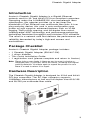
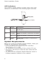
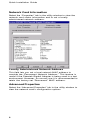
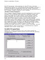
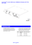
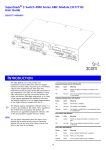
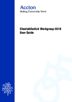
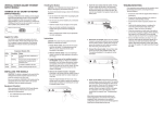
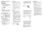
Cheetah Gigabit Adapter
Quick Installation Guide
Cheetah Gigabit Adapter
Introduction
Accton’s Cheetah Gigabit Adapter is a Gigabit Ethernet
network card for 32- and 64-bit PCI bus compliant computers.
Operating under the 1000BASE-SX short-wavelength laser
specification, this adapter provides up to ten times the
bandwidth of Fast Ethernet over multimode fiber links. A true
plug-and-play device, this card is auto-configurable upon
power up and supports advanced features such as VLAN
tagging, QoS priority queuing, and full-duplex flow control.
Leading-edge ASIC technology and performance-enhancing
techniques maximize throughput and minimize CPU utilization.
The result is a network card that delivers the performance and
reliability demanded by today’s high-end servers and
workstations.
Package Checklist
Accton’s Cheetah Gigabit Adapter package includes:
•
•
•
•
1 Cheetah Gigabit Adapter (EN1407-SX)
1 driver diskette
This Quick Installation Guide
1 registration card (please complete and return to Accton)
Note: Please inform your dealer is there are any incorrect, missing or
damaged parts. If possible, retain the carton, including the original
packing materials. Use them again to repack the product in case
there is a need to return it for repair.
Hardware Description
The Cheetah Gigabit Adapter is designed for 32-bit and 64-bit
PCI-bus computers. The SC fiber connector supports
1000Mbps transmissions at half and full duplex over 62.5/125
and 50/125 µm multimode fiber cable.
3
Quick Installation Guide
LED Indicators
The Cheetah Gigabit Adapter includes three status LED
indicators, as described in the following figure and table.
LED
Status
Description
Link
On Green
Indicates a valid 1000BASE-SX connection on
the fiber port.
Off
Indicates the fiber port is not connected.
On Green
Indicates the adapter is operating in full-duplex
mode.
Off
Indicates the adapter is operating in half-duplex
mode.
Flashing
Green
Indicates that the adapter is transmitting or
receiving data.
FDX
Act
System Requirements
Before you install the Cheetah Gigabit Adapter, check your
system for the following requirements:
• A PC and BIOS that support the PCI Local Bus
Specification v2.0 or later
• An available bus-mastering 32-bit or 64-bit PCI slot
• 62.5/125 or 50/125 µm multimode fiber cable with SC
connectors
• An IEEE 802.3z-compliant Gigabit Ethernet switch or
buffered repeater installed in your network
4
Cheetah Gigabit Adapter
Installation
Warnings:
· This network adapter requires a PC and BIOS that support the PCI
Local Bus Specification v2.0 or later. If you are installing in an older
PC model, upgrade the BIOS to the latest version.
· Network cards are sensitive to static electricity. To protect the card,
avoid touching its electrical components and always touch the metal
chassis of your computer before handling the card.
· Backup your driver diskette and use the copy as the working diskette
to protect the original from accidental damage.
1. Switch off the computer, unplug the power cord, and
remove the computer’s cover.
2. Select an available 32-bit or 64-bit bus-mastering PCI slot
and remove the cover bracket.
• Use a 64-bit PCI slot if your PC supports this standard.
• If using a 32-bit PCI slot, the end of the card’s edge
connector will be exposed. Be careful that it does not
touch any conducting parts on the PC motherboard.
Note: Some PC motherboard designs may not provide adequate space
behind all 32-bit PCI slots to properly install the network card.
3. Install the network card into the slot so that it is firmly
seated. Then, screw the card’s bracket securely into the
PC’s chassis.
4. Replace the computer’s cover and power it on. The
Cheetah Gigabit Adapter should be automatically
configured by the host computer’s BIOS. If you have
problems, see the checklist items in “Troubleshooting.”
5. Install the appropriate network driver for your operating
system. Drivers can be found on the driver diskette. See
“Driver Installation and Configuration” for more information.
5
Quick Installation Guide
Driver Installation and Configuration
The diskette labeled “Driver Diskette,” that comes with the
package contains all the software drivers available for the
Cheetah Gigabit Adapter. A RELEASE.TXT file, describing the
contents of the diskette is found in the root directory. Different
drivers are stored in separate subdirectories, which also
include a text file. Select the driver you need for your system
and refer to the text file for the installation and configuration
procedure. Any new or updated drivers can be downloaded
from Accton’s Web site at http://www.accton.com.
Connecting Fiber Cable
To connect to a 1000BASE-SX Gigabit Ethernet device, use
the SC connector on the network card and 62.5/125 or
50/125 µm multimode fiber optic cable. Note that for 62.5/125
µm cable with ST connectors, Accton provides an optional SC
to ST plug converter (Cheetah ST Converter, ST5002).
The attached device must be within the distance limitations
specified by the IEEE 802.3z 1000BASE-SX specification.
Observe the guidelines in the following table.
1000BASE-SX Fiber Cable Lengths
Core Diameter
Modal Bandwidth
Maximum Length
62.5/125 microns
160 MHz/km
220 m (722 ft)
200 MHz/km
275 m (902 ft)
400 MHz/km
500 m (1641 ft)
500 MHz/km
550 m (1805 ft)
50/125 microns
6
Cheetah Gigabit Adapter
Use the following procedure to make an SC connection to the
network.
Caution: This network card uses lasers to transmit signals over fiber optic
cable. The lasers are compliant with the requirements of a Class
1 Laser Product and are inherently eye safe in normal operation.
However, you should never look directly at the transmit port
when it is powered on.
1. Remove and keep the SC connector’s cover. When not
connected to a fiber cable, the cover should be replaced to
protect the optics.
2. Connect one end of the cable to the card’s SC connector
and the other end of the cable to the fiber connector on the
other device. Note that because SC connectors are keyed,
they can only be attached in one orientation.
3. Make certain that the network device you are connecting to
is compliant with IEEE 802.3z 1000BASE-SX.
Configuration and Diagnostic Utility
This section describes the configuration and diagnostic utility
available when using the Cheetah Gigabit Adapter in a
Windows NT 4.0 environment.
Note: Prior to installing the Windows NT 4.0 driver, make sure you have
upgraded to NT Service Pack 3 or later.
When you install the Windows NT 4.0 driver, the advanced
configuration utility is also installed. You can run this utility by
clicking on the “Properties” button for the card in the
“Network” control panel applet. Using this utility you can
perform the following procedures:
• View the adapter’s status and PCI setup information.
• Configure the adapter’s advanced properties, such as link
parameters, Packet Propulsion threshold and Jumbo
Frame support.
• Configure VLAN tag capabilities and edit the VLAN ID table.
• Perform diagnostics to test the adapter’s basic functions.
How to Run the Windows NT Utility
Follow these steps from the Windows NT 4.0 desktop.
1. Double-click on the “My Computer,” “Control Panel,” and
“Network” icons. The “Network” dialog box appears.
2. Click on the “Adapters” tab and select the Cheetah Gigabit
Adapter in the list box.
3. Click on the “Properties” button to run the utility.
7
Quick Installation Guide
Network Card Information
Select the “Properties” tab in the utility window to view the
network card status information and to set a locally
administered network address.
Locally Administered Network Address
This field lets you set a local network MAC address to
override the “Permanent Network Address.” This feature is
useful if the Cheetah Gigabit Adapter is being used in a test
environment. However, for normal use it is recommended to
retain the factory-set “Permanent” MAC address.
Advanced Properties
Select the “Advanced Properties” tab in the utility window to
view the network card’s configuration options.
8
Cheetah Gigabit Adapter
Link Parameters
The network card’s link speed, PHY type (physical connection
to the network) and duplex mode can all be set from this page.
However, if the “AutoNegotiate Link Parameters” box is
checked these parameters are automatically determined and
the configuration options greyed out. For most Gigabit
Ethernet devices it is recommended to use Auto-Negotiation to
set the link parameters. (Note that the adapter’s link speed can
only be 1000Mbps and the PHY type is always G/MII.)
Packet Propulsion
The Packet Propulsion configuration option sets the packetsize threshold at which Propulsion technology is used to burst
packets across the PCI bus. Propulsion increases the
throughput of small packets by coalescing transfers across
the PCI bus. This minimizes host CPU interrupts and bus
arbitrations.
Use the slider control or edit box to set the packet-size
threshold level in bytes (from 0 to 1514, or 9014 if Jumbo
Frames is selected). Packets of sizes below this threshold
use the Propulsion technique, packets above use the normal
scatter-gather method.
There is a trade off between the Packet Propulsion and
scatter-gather methods. Packet Propulsion uses more bus
resources whereas scatter-gather uses more CPU
resources. The optimum setting of the threshold level for a
particular environment depends on various factors, such as
9
Quick Installation Guide
the PC hardware, other devices on the PCI bus, and the
applications being run. Considering all the variables involved, it
is recommended to experiment with the Packet Propulsion
threshold to find the setting that maximizes the performance of
the Cheetah Gigabit Adapter in your system.
Jumbo Frame Support
The Cheetah Gigabit Adapter can be configured to use Jumbo
Frames. This increases the maximum Ethernet frame size
from 1514 bytes up to 9014 bytes. Using Jumbo Frames
greatly reduces the packet processing overhead and can
boost throughput by up to 300% for bulk data transfers.
Note that to use Jumbo Frames, both communicating
computers must have network cards that support this feature.
Also at full duplex, all switches in the network between the two
end computers must be able to accept the extended frame
size. With half-duplex connections, all devices in the collision
domain would need to support Jumbo Frames. LAN
partitioning, either physical or logical using VLAN tags, can be
implemented to allow computers to simultaneously support
standard and Jumbo frame sizes.
VLAN Properties
Select the “VLAN Properties” tab in the utility window to
configure the adapter’s VLAN options and to edit the 16-entry
VLAN ID table.
10
Cheetah Gigabit Adapter
Using VLANs
The Cheetah Gigabit Adapter supports the IEEE 802.1Q VLAN
standard and can be configured to participate in a network
with other devices that use VLANs.
An IEEE 802.1Q VLAN is a group of ports that can be located
anywhere in the network, but communicate as though they
belong to the same physical segment. VLANs help to simplify
network management by allowing you to move devices to a
new VLAN without having to change any connections. VLANs
can be easily organized to reflect departmental groups (such
as Marketing or R&D) or usage groups (such as e-mail or
video conferencing).
VLANs provide greater network efficiency by reducing
broadcast traffic, but also allow you to make network changes
without having to update IP addresses or IP subnets. VLANs
inherently provide a high level of network security, since traffic
must pass through a router or a Layer 3 switch to reach a
different VLAN.
Usually VLANs are configured within IEEE 802.1Q VLANenabled switches in the network where ports are assigned to
specific VLAN IDs. The Cheetah Gigabit Adapter allows up to
16 VLAN IDs to be configured directly within the card, so a
network server can share its resources with up to 16 VLANs
through just one switch link. This avoids the expense of having
multiple adapters in a server, and significantly reduces the
latency between clients and the server.
Note: The VLAN IDs configured within the adapter card must match those
in the IEEE 802.1Q-compliant switches throughout the network.
Also, the adapter must be attached to a switch port that permits
overlapping VLANs.
Traffic Priority
The Cheetah Gigabit Adapter supports the IEEE 802.1p
Quality of Service standard. Each VLAN is assigned a priority
level in the VLAN ID table. Defining priority levels in the adapter
card allows it to work with other network devices to deliver
higher priority packets first.
Note that the IEEE 802.1p standard must be supported by the
other devices in the network. Refer to the documentation of
your network devices for configuration options on handling
frames with priority tags.
VLAN Table Maintenance
The Cheetah Gigabit Adapter’s VLAN configuration features a
16-entry VLAN ID table. Just click on the “Insert” button to add
an entry to the table. Each entry requires a VLAN ID number in
the range of 0 to 4095 and a user priority level of 0 (lowest) to
7 (highest). The “Modify” and “Delete” buttons can be used to
edit or remove entries from the table.
11
Quick Installation Guide
The first entry at the top of the table is the VLAN ID that is
used in outbound VLAN tagged frames from the adapter. All
entries in the table are used for filtering inbound frames with
unlisted VLAN IDs. Note that the switch port the adapter is
connected to should be assigned to the VLAN groups
specified in the table or permit automatic VLAN registration
with GVRP.
VLAN Capabilities
Three check-box options at the bottom of the VLAN Properties
page provide control of the VLAN tagging. “Enable VLAN
Filtering” must be checked for the card’s VLAN features to
operate. If “Strip Inbound VLAN Tags” is checked, all incoming
frames are processed as normal frames. When “Insert
Outbound VLAN Tags” is checked, the VLAN ID from the top
entry in the table will be appended onto every frame sent from
the card.
Note that when you make a change to the VLAN Capabilities
you must reboot the computer for the changes to take effect.
Network Card Diagnostics
Select the “Diagnostics” tab in the utility window to test the
basic functions of the adapter and its ability to communicate
over the network with another adapter.
12
Cheetah Gigabit Adapter
Local Tests
These tests can be used to test the basic functions of the
adapter. Select the “Run Loopback Tests” and “Run Internal
Tests” check boxes either together or separately. The tests to
be performed will show “Ready” as the status in the test list
box. Then click on the “Run Local Tests” button to start the
tests. The progress of each test is shown by the “Test
Progress” status bar. When the tests are complete, click on
the “View Test Results” button to display the test results.
Send and Receive Test
This test verifies that the network cable is connected
correctly, so that the network card can transmit and receive
data.
The test requires two computers with the Cheetah Gigabit
Adapter installed. One computer generates and sends test
messages, the other computer receives the test messages
and transmits them back to the sender.
Note: You should run the Local Tests before running the Send and Receive
Test to ensure that the card’s basic functions are working properly.
To run the test, on one computer be sure the configuration
utility is running to enable it as the receiver. On the other
computer, simply click on the “Run” button to start sending
test messages. The progress of the test is shown by the
“Server Activity” status bar. You can view the test results by
clicking on the “View Test Results” button.
13
Quick Installation Guide
Troubleshooting
Check the following troubleshooting items before contacting
Accton Technical Support.
PCI Compatibility
Some PCI computers are not self-configuring and require you
to perform some or all of the following functions by changing
motherboard jumpers and/or configuring the BIOS Setup
program:
• Make sure your BIOS correctly supports the PCI Local
Bus Specification v2.0 or later and upgrade your computer
BIOS to the latest version.
• Verify that the PCI slot is an enabled busmaster slot and
not a slave PCI slot. In some computers the PCI slot must
be configured to enable bus mastering. Refer to your PC’s
manual and check the PCI BIOS Setup program to be sure
the PCI slot is an enabled busmaster slot.
• In some computers, you may be required to disable Plug ‘n
Play (PnP) in the BIOS Setup program if resources are not
properly assigned between installed cards.
• Some computers may require you to reserve interrupts
and memory addresses for installed ISA cards to prevent
PCI cards from using the same settings. Refer to your
PC’s manual and check the PCI BIOS Setup program
configuration options for ISA cards.
• Make sure the PCI slot is configured to support INTA.
• Be sure that INTA for the slot is assigned to a free interrupt
(IRQ) number.
• Check the BIOS Setup program’s PCI parameters for the
slot where the Cheetah Gigabit Adapter is installed. Be
sure the slot is configured for level-triggered interrupts
instead of edge-triggered interrupts. An example of typical
PCI parameters follows:
PCI Slot #:
Master:
Slave:
Latency Timer:
Interrupt Type:
Interrupt Number:
(slot number where the network card is installed)
Enabled
Enabled
40 (range is 20 to 255)
Level-Triggered
(choose any number the BIOS Setup supplies
that does not conflict with another installed card)
Note: The wording of these parameters varies with different computers,
and not all parameters may be configurable.
Always consult your computer manual for information on
changing motherboard jumper settings and BIOS Setup
program parameters for use with PCI network cards. If you
set a motherboard jumper and modify the computer’s BIOS
Setup, make sure the jumper and BIOS settings match.
14
Cheetah Gigabit Adapter
Adapter Installation Problems
If your computer can’t find the Cheetah Gigabit Adapter or the
network driver doesn’t install correctly, check the following:
• Make sure the adapter is securely seated in the PCI slot.
Check for any hardware problems, such as physical
damage to the card’s edge connector.
• Try the card in another PCI busmaster slot. If all fails, test
with another Cheetah Gigabit Adapter that is known to
operate correctly.
• Check for resource conflict in the PCI configuration. See
“PCI Compatibility.”
• Make sure your computer is using the latest BIOS
available.
• If there are other network adapters in the computer, they
may be causing conflict. Remove all other adapters from
the computer and test the Accton adapter separately.
• Check for a defective computer or PCI bus by trying the
adapter in another computer that is known to operate
correctly.
Network Connection Problems
If the Link LED on the adapter’s bracket does not light, or if
you can’t access any network resources from the computer.
Check the following:
• Check the rating of the fiber cable and make sure its length
is within the IEEE 802.3z 1000BASE-SX requirements.
• Inspect all network cables and connections. Make sure the
cable is securely attached to the adapter’s connector.
• Make sure the correct software driver is installed for your
operating system. If necessary, try reinstalling the driver.
• Make sure the computer and other network devices are
receiving power.
• Make sure the adapter is connected to a Gigabit Ethernet
switch or buffered repeater port that is configured for AutoNegotiation. If the card’s duplex mode has been configured
manually, check that it matches that of the network device
port.
• The network device port that the adapter is attached to
may be defective. Try using another port on the device.
• If you cannot access a Windows or NetWare service on
the network, check that you have enabled and configured
the service correctly. If you cannot connect to a particular
server, be sure that you have access rights and a valid ID
and password.
• If you cannot access the Internet, be sure you have
configured your system for TCP/IP.
15
Quick Installation Guide
Compliances
FCC Class B Certification
This device complies with Part 15 of the FCC Rules. Operation
is subject to the following conditions:
1. This device may not cause harmful interference, and
2. This device must accept any interference received,
including interference that may cause undesired operation.
Warning! This equipment has been tested and found to comply with the limits for a
Class B digital device, pursuant to Part 15 of the FCC Rules. These limits are
designed to provide reasonable protection against harmful interference in a
residential installation. This equipment generates, uses and can radiate radio
frequency energy and, if not installed and used in accordance with the instructions,
may cause harmful interference to radio communications. However, there is no
guarantee that interference will not occur in a particular installation. If this equipment
does cause harmful interference to radio or television reception, which can be
determined by turning the equipment off and on, the user is encouraged to try to
correct the interference by one or more of the following measures:
•
Reorient or relocate the receiving antenna.
•
Increase the distance between the equipment and receiver.
•
Connect the equipment into an outlet on a circuit different
from the one which the receiver is connected to.
•
Consult the dealer or an experienced radio/TV technician
for help.
You are cautioned that changes or modifications not expressly
approved by the party responsible for compliance could void
your authority to operate the equipment.
Attach 62.5/125 or 50/125 µm multimode fiber cable to the SC
port.
Note: In order to maintain compliance with the limits of a Class B digital device,
Accton requires that you use a quality interface cable when connecting to this
device. Changes or modifications not expressly approved by Accton could void the
user's authority to operate this equipment. Suggested cable type is 62.5/125 or
50/125 µm multimode fiber cable for the SC port.
CSA Statement (Canada)
This digital apparatus does not exceed the Class B limits for
radio noise emissions from digital apparatus set out in the
Radio Interference Regulations of Industry Canada.
Le présent appareil numérique n’émet pas de bruits radioélectriques dépassant les limites applicables aux appareils
numériques de la classe B prescrites dens le Règlement sur
le brouillage radioélectrique édicté par l’Industrie.
16
Cheetah Gigabit Adapter
VCCI Class B Compliance (Japan)
CE Mark Declaration of Conformance
This is to certify that this product complies with ISO/IEC Guide
22 and EN45014. It conforms to the following specifications:
EMC:
EN55022(1988)/CISPR-22(1985)
IEC 1000-4-2(1995)
IEC 1000-4-3(1995)
IEC 1000-4-4(1995)
IEC 1000-4-6(1995)
class B
4kV CD, 8kV AD
3V/m
1kV - (power line)
3Vrms
This product complies with the requirements of the Low
Voltage Directive 73/23/EEC and the EMC Directive 89/336/
EEC, and carries the CE Mark accordingly.
Class I Laser Safety Compliance
Warning: Fiber Optic Port Safety
Never look at the transmit laser while it is powered on. Also,
never look directly at the fiber TX port and fiber cable ends
when they are powered on.
Avertissment: Ports pour fibres optiques - sécurité
sur le plan optique
Ne regardez jamais le laser tant qu'il est sous tension. Ne
regardez jamais directement le port TX (Transmission) à fibres
optiques et les embouts de câbles à fibres optiques tant qu'ils
sont sous tension.
Warnhinweis: Faseroptikanschlüsse - Optische
Sicherheit
Niemals ein Übertragungslaser betrachten, während dieses
eingeschaltet ist. Niemals direkt auf den Faser-TX-Anschluß
und auf die Faserkabelenden schauen, während diese
eingeschaltet sind.
17
Quick Installation Guide
Specifications
General Specifications
Standards Conformance
IEEE 802.3z 1000BASE-SX
IEEE 802.3x Full-duplex flow control
IEEE 802.1Q VLANs
IEEE 802.1p Quality of Service
PCI Bus v2.1
Host Interface
32-bit and 64-bit bus master PCI
Ethernet Data Rate
1000 Mbps
Transmission Mode
Half and full duplex, auto-negotiation
Media Type
62.5/125 µm fiber cable, max. 220m (722 ft)
50/125 µm fiber cable, max. 550m (1804 ft)
Optical Wavelength
Transmitter: 840 nm to 860 nm
Receiver: 770 nm to 860 nm
Media Connection
1 fiber optic SC connector
Interrupt
INTA
Configuration
16-entry VLAN table, 8 priority levels
Jumbo Frame support
Packet Propulsion threshold level
LED Indicators
Link, full/half duplex, activity
Power Requirement
+5VDC, 900 mA max.
Dimensions
79 x 16.5 mm (3.11 x 6.50 in)
Weight
80g (2.8 oz)
Environmental
Temperature
0 to 60° C / 32 to 140° F (Standard Operating)
-40 to 85° C / -40 to 185° F (Non-operating)
Humidity
5 to 95% (Non-condensing)
Certification
CE Mark
EN50081-1, EN55022 (CISPR 22) Class B
IEC1000-4-2/3/4/6
Emissions
FCC Class B, VCCI Class B, CISPR Class B
Software Drivers
ODI Drivers
NetWare Server 3.2, 4.11, 5.0
NDIS Drivers
Windows NT 4.0
Windows 98
Windows 95 OSR2
Windows 95
Windows 2000
Unix Drivers
Linux 2.0.35 or later
18
Warranty
Accton warrants to the original owner that the product delivered in this
package will be free from defects in material and workmanship for the
lifetime of the product. For the warranty to apply, you must register your
purchase by returning the registration card indicating the date of
purchase and including proof of purchase. There will be a minimal charge
to replace consumable components, such as fuses, power transformers,
and mechanical cooling devices. The warranty does not cover the
product if it is damaged in the process of being installed. Accton
recommends that you have the company from whom you purchased this
product install it.
THE ABOVE WARRANTY IS IN LIEU OF ANY OTHER WARRANTY,
WHETHER EXPRESS, IMPLIED OR STATUTORY, INCLUDING BUT NOT
LIMITED TO ANY WARRANTY OF MERCHANTABILITY, FITNESS FOR A
PARTICULAR PURPOSE, OR ANY WARRANTY ARISING OUT OF ANY
PROPOSAL, SPECIFICATION OR SAMPLE. ACCTON SHALL NOT BE
LIABLE FOR INCIDENTAL OR CONSEQUENTIAL DAMAGES. ACCTON
NEITHER ASSUMES NOR AUTHORIZES ANY PERSON TO ASSUME FOR
IT ANY OTHER LIABILITY.
Copyright
Copyright © 1999 by Accton Technology Corporation. All rights reserved.
No part of this document may be copied or reproduced in any form or by
any means without the prior written consent of Accton Technology
Corporation.
Trademarks
Accton is a trademark of Accton Technology Corporation. Other
trademarks or brand names mentioned herein are trademarks or
registered trademarks of their respective companies.
Disclaimer
Accton makes no warranties with respect to this documentation and
disclaims any implied warranties of merchantability, quality, or fitness for
any particular purpose. The information in this document is subject to
change without notice. Accton reserves the right to make revisions to
this publication without obligation to notify any person or entity of any
such changes.
International Headquarters
No. 1 Creation Road III,
Science-based Industrial Park
Hsinchu 300, Taiwan, R.O.C.
Phone: 886-3-5770-270
FAX: 886-3-5770-267
Internet: [email protected]
USA Headquarters
6 Hughes
Irvine, CA 92618
Phone Numbers Sales:
800-926-9288
Support: 888-398-4101 or 949-707-4847
RMA:
800-762-4968
FAX: 949-707-2460
EN1407-SX
E0899-R01
150016-102