1
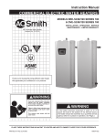
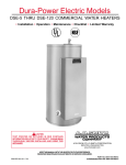
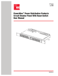
Models DRE & DVE - 52/80/120
COMMERCIAL ELECTRIC WATER HEATERS
• INSTALLATION • OPERATION • MAINTENANCE • LIMITED WARRANTY
CAUTION
TEXT PRINTED OR UNDERLINED IN RED
CONTAINS INFORMATION RELATIVE TO YOUR
SAFETY. PLEASE READ THOROUGHLY BEFORE
ATTEMPTING ANY CONVERSION.
A DIVISION OF A.O. SMITH CORPORATION
MCBEE, SOUTH CAROLINA
www.hotwater.com
PLACE THESE INSTRUCTIONS ADJACENT TO HEATER AND
NOTIFY OWNER TO KEEP FOR FUTURE REFERENCE.
PRINTED IN U.S.A. 0906
PART NO. 196674-001
1
Rough-in-Dimensions
Model Number
DRE/DVE-52
DRE/DVE-80
DRE/DVE-120
Tank Capacity in Gallons
50
80
119
A
55 1/4
59 1/2
62 1/4
Get to know your water heater
2
B
21 3/4
25 1/4
29 1/2
Inlet/Outlet
1 1/4
1 1/4
1 1/4
Contents
Page
Amperage Table/Overcurrent Protection ................. 16
Heater Circuits - DVE Models .................................. 16
Control Circuit .......................................................... 16-17
Power Circuit ............................................................ 18-21
OPERATION
General .................................................................... 22
Filling ........................................................................ 22
Startup ...................................................................... 22
High Temperature Limiting Device ........................... 22
Draining .................................................................... 22
Circulating Pump ..................................................... 22
MAINTENANCE
General .................................................................... 23
Flushing ................................................................... 23
Sediment Removal ................................................... 23
Lime Scale Removal ................................................ 23-24
Checklist .................................................................. 24
Replacement Parts .................................................. 24
LEAKAGE CHECKPOINTS ..................................... 25
LIMITED WARRANTY .............................................. 26
Page
ROUGH-IN-DIMENSIONS .......................................
2
GET TO KNOW YOUR WATER HEATER ...............
2
RECOVERY CAPACITY ...........................................
3
APPROVALS ............................................................
3
MODEL AND RATING PLATE ..................................
4
FOREWORD ............................................................
4
GENRAL SAFETY INFORMATION ..........................
4
INSTALLATION ........................................................
5
Required Ability ........................................................
5
General ....................................................................
5
Location ...................................................................
5
Waterline Connections .............................................
5
Relief Devices .......................................................... 5-6
Temperature Limiting Control(s) ..............................
6
Temperature Regulation ..........................................
6
PIPING DIAGRAMS ................................................. 7-14
ELECTRICAL
General .................................................................... 14
Branch Circuit .......................................................... 15
Recovery Rating
RECOVERY RATE IN GALLONS PER HOUR*
Temperature Rise °F
Models
DRE/DVE
DRE/DVE
DRE/DVE
DRE/DVE
DRE/DVE
DRE/DVE
DRE/DVE
DRE/DVE
DRE/DVE
DRE/DVE
DRE/DVE
DRE/DVE
DRE/DVE
Standard
KW Input
6
9
12
13.5
15
18
24
27
30
36
40.5
45
54
BTU/
Hour
20,478
30,717
40,956
46,075
51,195
61,434
81,912
92,151
102,390
122,868
138,226
153,585
184,302
30°
82
123
164
184
205
246
328
369
410
492
554
615
738
40°
62
92
123
138
154
184
246
276
307
369
418
461
553
50°
49
74
98
111
123
148
197
221
246
295
3332
369
443
60°
41
62
82
92
102
123
164
184
205
246
277
307
369
70°
35
53
70
79
88
105
140
158
176
211
237
263
316
80°
31
46
61
69
77
92
123
138
154
184
208
230
277
90°
27
41
55
62
68
82
109
123
137
164
185
205
246
100° 110°
25
22
37
34
49
45
55
50
61
56
74
67
98
89
111 101
123 112
148 134
166 151
184 168
221 201
*Figured at 1 KW (3413 Btu) = 4.1 gallons at 100°F temperature rise.
To determine recovery rate per minute, divide recovery rate per hour by 60.
Approvals
All models bear the
National Sanitation
Foundation seal of
approval.
All models are listed
by Underwriters
Laboratories Inc.
3
120°
21
31
41
46
51
61
82
92
102
123
138
154
184
130°
19
28
38
43
47
57
76
85
95
113
128
142
170
140°
18
26
35
40
44
53
70
79
88
105
119
132
158
Model and Rating
Foreword
Detailed installation diagrams are in this manual. These diagrams
will serve to provide the installer with a reference for the materials
and method of piping suggested. IT IS NECESSARY THAT ALL
WATER PIPING AND THE ELECTRICAL WIRING BE INSTALLED
AND CONNECTED AS SHOWN IN THE DIAGRAMS.
jurisdiction shall be consulted before installations are made.
BE SURE TO TURN OFF POWER WHEN WORKING ON OR
NEAR THE ELECTRICAL SYSTEM OF THE HEATER. NEVER
TOUCH ELECTRICAL COMPONENTS WITH WET HANDS OR
WHEN STANDING IN WATER. WHEN REPLACING FUSES
ALWAYS USE THE CORRECT SIZE FOR THE CIRCUIT. SEE
PAGE 16 THROUGH 21.
Particular attention should be given to the installation of
thermometers at the locations indicated in the diagrams as these
are necessary for checking the operation of the heater.
The principal components of the heater are identified on page 2.
The model and rating plate on page 4 interprets certain markings
into useful information. Both of these references should be used
to identify the heater, its components and optional equipment.
In addition to these instructions, the equipment shall be installed
in accordance with those installation regulations in force in the
local area where the installation is to be made. Authorities having
General Safety Information
that the hot water faucet be opened for several minutes at the kitchen
sink before using any electrical appliance connected to the hot water
system. If hydrogen is present there will probably be an unusual
sound such as air escaping through the pipe as the water begins to
flow. THERE SHOULD BE NO SMOKING OR OPEN FLAME NEAR
THE FAUCET AT THE TIME IT IS OPEN.
PRECAUTIONS
DO NOT USE THIS APPLIANCE IF ANY PART HAS BEEN
UNDER WATER. Immediately call a qualified service technician
to inspect the appliance and to replace any part of the control
system and any gas control which has been under water.
INSULATION BLANKETS
IF THE UNIT IS EXPOSED TO THE FOLLOWING, DO NOT
OPERATE HEATER UNTIL ALL CORRECTIVE STEPS HAVE
BEEN MADE BY A QUALIFIED SERVICEMAN.
Insulation blankets available to the general public for external
use on water heaters are not approved for use on your A.O.
Smith water heater. The purpose of an insulation blanket is to
reduce the standby heat loss encountered with storage tank
water heaters. Your A.O. Smith water heater meets or exceeds
the ASHRAE/IES 90.1b 1992 standards with respect to insulation
and standby loss requirements, making an insulation blanket
unnecessary.
1. EXTERNAL FIRE.
2. DAMAGE.
3. FIRING WITHOUT WATER.
GROUNDING INSTRUCTIONS
This water heater must be grounded in accordance with the
National Electric Code and/or local codes. These must be followed
in all cases.
WARNING
Should you choose to apply an insulation blanket to this heater,
you should follow these instructions (See "Getting to know your
water heater" on page 2 for identification of components mentioned
below). Failure to follow these instructions can result in fire,
asphyxiation, serious personal injury or death.
This water heater must be connected to a grounded metal,
permanent wiring system; or an equipment grounding conductor
must be run with the circuit conductors and connected to the
equipment grounding terminal or lead on the water heater.
• Do not cover the temperature & pressure relief valve.
• Do not cover the instruction manual. Keep it on the side of
the water heater or nearby for future reference.
• Do obtain new labels from A.O. Smith for placement on the
blanket directly over the existing labels.
HYDROGEN GAS (FLAMMABLE)
CAUTION
HYDROGEN GAS CAN BE PRODUCED IN A HOT WATER
SYSTEM SERVED BY THIS HEATER THAT HAS NOT BEEN USED
FOR A LONG PERIOD OF TIME (GENERALLY TWO WEEKS OR
MORE). HYDROGEN GAS IS EXTREMELY FLAMMABLE. To
reduce the risk of injury under these conditions, it is recommended
WARNING
FAILURE TO FOLLOW THESE INSTRUCTIONS CAN RESULT
IN SERIOUS PERSONAL INJURY OR DEATH.
4
Installation
REQUIRED ABILITY
Locate the heater close to the point of major hot water usage and
the power supply.
• Try to make hot water piping and branch circuit wiring as short
as possible.
• Insulate hot and cold water piping where heat loss and
condensation may be a problem.
INSTALLATION OR SERVICE OF THIS WATER HEATER
REQUIRES ABILITY EQUIVALENT TO THAT OF A LICENSED
TRADESMAN IN THE FIELD INVOLVED. PLUMBING AND
ELECTRICAL WORK ARE INVOLVED.
GENERAL
THE HEATER SHOULD NOT BE LOCATED IN AN AREA WHERE
IT WILL BE SUBJECT TO FREEZING.
The installation must conform to these instructions and the local
code authority having jurisdiction. Grounding and electrical wiring
connected to the water heater must also conform to the current
version of the National Electrical Code NFPA-70 or for Canadian
requirements the current version of the Canadian Electric Code,
CAN/CSA-C22.2 No. M91. These codes may be obtained from
the following institutes; The NFPA-70 is available from the National
Fire Protection Association, 1 Batterymarch Park, Quincy, MA
02269. The CAN/CSA C22.2 No. M91 is available from the
Canadian Standards Association, 178 Rexdale Blvd., Toronto
Ontario, Canada M9W 1R3.
Suggested clearances from adjacent surfaces are 18 inches in
front for access to the controls and elements and 12 inches from
top. The heater may be installed on or against combustible
surfaces.
WATER LINE CONNECTIONS
This manual provides detailed installation diagrams (see back
section of this manual) for typical methods of application for the
water heaters. The water heater may be installed by itself, or with
a separate storage tank, on both single and two-temperature
systems. When used with a separate storage tank, the circulation
may be either by gravity or by means of a circulating pump. When
a circulating pump is used it is important to note that the flow rate
should be slow so that there will be a minimum of turbulence
inside the heater.
If your location requires the installation of the water heater to
comply with National Sanitation Foundation requirements, the
heater must be sealed to the floor so as to prevent seepage
underneath the heater. The following are recommended sealants
that may be used on all types of flooring except concrete GE
Silicone Seal RTV-120, 103, 108, and 109.
LOCATION
CAUTION
A closed system will exist if a check valve, pressure reducing
valve, or a water meter is installed in the cold water line between
the water heater and street main (or well).
For proper installation, the heater should be installed on a level
surface.
LOCATE THE WATER HEATER NEAR A FLOOR DRAIN. THE
HEATER SHOULD BE LOCATED IN AN AREA WHERE
LEAKAGE FROM THE HEATER OR CONNECTIONS WILL NOT
RESULT IN DAMAGE TO THE ADJACENT AREA OR TO LOWER
FLOORS OF THE STRUCTURE.
Excessive pressure may develop causing premature tank failure
or intermittent relief valve operation. This type of failure is not
covered by the limited warranty. An expansion tank may be
required in the inlet supply line between the appliance and the
meter or valve to compensate for the thermal expansion of water.
WHEN SUCH LOCATIONS CANNOT BE AVOIDED, A SUITABLE
DRAIN PAN SHOULD BE INSTALLED UNDER THE HEATER.
Such pans should be fabricated with sides at least 2" deep, with
length and width at least 2" greater than the diameter of the heater
and must be piped to an adequate drain. Drain pans suitable for
these heaters are available from your distributor or Product Service
Division, A.O. Smith Water Heater Parts Fulfillment, 125 Southeast
Parkway, Franklin, TN 37068.
If a water heater is installed in a closed water system, contact the
water supplier or local plumbing inspector on how to control this
situation.
RELIEF DEVICES
CAUTION
TO REDUCE THE RISK OF EXCESSIVE PRESSURES AND
TEMPERATURE IN THIS WATER HEATER, INSTALL
TEMPERATURE AND PRESSURE PROTECTIVE EQUIPMENT
REQUIRED BY LOCAL CODES but not less than a combination
temperature and pressure relief valve certified by a nationally
recognized testing laboratory that maintains periodic inspection
of production of listed equipment or materials, as meeting the
requirements for Relief Valves for Hot Water Supply Systems,
ANSI Z21.22 /CSA 4.4 (current version).
Water heater life depends upon water quality, water pressure and
the environment in which the water heater is installed. Water
heaters are sometimes installed in locations where leakage may
result in property damage, even with the use of a drain pan piped
to a drain. However, unanticipated damage can be reduced or
prevented by a leak detector or water shut-off device used in
conjunction with a piped drain pan. These devices are available
from some plumbing supply wholesalers and retailers, and detect
and react to leakage in various ways:
This valve must be marked with a maximum set pressure not to
exceed the marked maximum working pressure of the water heater.
INSTALL THE VALVE INTO AN OPENING PROVIDED AND
MARKED FOR THIS PURPOSE IN THE WATER HEATER, AND
ORIENT IT OR PROVIDE TUBING SO THAT ANY DISCHARGE
FROM THE VALVE WILL EXIST ONLY WITHIN 6 INCHES ABOVE,
OR AT ANY DISTANCE BELOW THE STRUCTURAL FLOOR AND
CANNOT CONTACT ANY LIVE ELECTRICAL PART. THIS
DISCHARGE OPENING MUST NOT BE BLOCKED OR REDUCED
IN SIZE UNDER ANY CIRCUMSTANCES.
• Sensors mounted in the drain pan that trigger an alarm or turn
off the incoming water to the water heater when leakage is
detected.
• Sensors mounted in the drain pan that turn off the water supply
to the entire home when water is detected in the drain pan.
• Water supply shut-off devices that activate based on the water
pressure differential between the cold water and hot water pipes
connected to the water heater.
• Devices that will turn off the gas supply to a gas water heater
while at the same time shutting off its water supply.
5
The pressure setting of the relief valve should not exceed the
pressure capacity of any component in the system. The
temperature setting of the relief valve should not exceed 210°F.
SMALL CHILDREN TO USE A HOT WATER TAP, OR TO DRAW
THEIR OWN BATH WATER. NEVER LEAVE A CHILD OR
DISABLED PERSON UNATTENDED IN A BATHTUB OR SHOWER.
An unplugged 3/4" relief valve opening is provided for installing
temperature and pressure relief valve.
THE WATER HEATER SHOULD BE LOCATED IN AN AREA
WHERE THE GENERAL PUBLIC DOES NOT HAVE ACCESS
TO SET TEMPERATURES.
TEMPERATURE LIMITING CONTROL(S)
SETTING THE WATER HEATER TEMPERATURES AT 120°F
WILL REDUCE THE RISK OF SCALDS. Some states require
settings at specific lower temperatures.
Both the DVE and DRE model water heaters incorporate high
temperature cutoffs. In the event of high temperature cutoff
operation, the reason for the operation of the high temperature
cutoff operation must be determined and corrected. Once the
situation has been corrected the high temperature cutoff(s) may
be reset in the following manner:
The water temperature is controlled in the DVE models with a
single thermostat located on the right front of the heater, just inside
the control cabinet. This control is set at 140°F at the factory and
has a fixed 5°F differential. The DRE models have multiple
thermostats depending on the configuration purchased. These
thermostats are also set at 140°F and have a 5-15°F differential.
A.O. Smith recommends setting the dial at the lowest setting which
produces an acceptable hot water supply. This will always give
the most energy efficient operation.
DVE Models
The DVE models have a single immersion-type high temperature
cutoff control in the control circuit, see DVE CONTROL CIRCUIT
DIAGRAMS. This high temperature cutoff is factory set to open at
190°F (88°C). To manually reset the control you must:
1.
2.
3.
4.
Disconnect the power to the heater.
Allow the tank to cool to approximately 120°F.
Remove the front control cover.
Press the manual reset button. The control will not
reset until it has cooled approximately 50°F (28°C).
Figure 1 shows the approximate time-to-burn relationship for
normal adult skin.
Valves for reducing point-of-use temperature by mixing cold and
hot water are available. Also available are inexpensive devices
that attach to faucets to limit hot water temperatures. Contact a
licensed plumber or the local plumbing authority.
DRE Models
The DRE models have multiple surface mounted combination high
temperature cutoff and thermostat controls. There is one of these
combination high temperature cutoff and thermostat controls for
each element in a DRE model, see DRE CIRCUIT DIAGRAMS.
Each of the high temperature controls is of the manual reset type.
To manually reset the controls:
1.
2.
3.
4.
Disconnect the power to the heater.
Allow the tank to cool approximately 160°F.
Remove the front control cover.
Press the manual reset button on each of the effected
controls. The control will not reset until it has cooled
approximately 30°F (17°C).
Once the control(s) has been reset the control cover should be
replaced prior to operating the heater.
TEMPERATURE REGULATION
DRE MODELS
Temperature
Setting
180°F
170°F
160°F
150°F
140°F
130°F
120°F
DANGER
THIS WATER HEATER IS EQUIPPED WITH AN ADJUSTABLE
THERMOSTAT TO CONTROL WATER TEMPERATURE. HOT
WATER TEMPERATURES REQUIRED FOR AUTOMATIC
DISHWASHER AND LAUNDRY USE CAN CAUSE SCALD BURNS
RESULTING IN SERIOUS PERSONAL INJURY AND/OR DEATH.
THE TEMPERATURE AT WHICH INJURY OCCURS VARIES WITH
THE PERSONS AGE AND TIME OF EXPOSURE. THE SLOWER
RESPONSE TIME OF CHILDREN, AGED, OR DISABLED
PERSONS INCREASES THE HAZARDS TO THEM. NEVER ALLOW
DVE MODELS
Time to produce 2nd & 3rd
Degree burns on adult skin
Nearly instantaneous
Nearly instantaneous
About 1/2 second
About 1-1/2 seconds
Less than 5 seconds
About 30 seconds
More than 5 minutes
FIGURE 1
6
Piping Diagrams
ONE TEMPERATURE WITH CIRCULATING LOOP
INSERT B
VACUUM RELIEF
VALVE. INSTALL PER
LOCAL CODES.
DANGER
TEMPERATURE SETTING SHOULD NOT EXCEED SAFE
TEMPERATURE AT FIXTURES. SEE WATER TEMPERATURE
CONTROL WARNING ON PAGE 6. IF HIGHER PREHEAT
TEMPERATURES ARE NECESSARY TO OBTAIN ADEQUATE
BOOSTER OUTPUT, ADD AN ANTI-SCALD VALVE FOR HOT
WATER SUPPLIED TO FIXTURES.
CAUTION: IF BUILDING COLD WATER SUPPLY HAS A BACKFLOW PREVENTER, CHECK VALVE OR WATER METER WITH
CHECK VALVE. PROVISIONS FOR THERMAL EXPANSION OF
WATER IN THE HOT WATER SYSTEM MUST BE PROVIDED.
*PIPE TO OPEN DRAIN
INSTALL IN ACCORDANCE WITH ALL LOCAL CODES.
7
INSERT B
DANGER
TEMPERATURE SETTING SHOULD NOT EXCEED SAFE TEMPERATURE AT FIXTURES.
SEE WATER TEMPERATURE CONTROL WARNING ON PAGE 6. IF HIGHER PREHEAT
TEMPERATURES ARE NECESSARY TO OBTAIN ADEQUATE BOOSTER OUTPUT, ADD
AN ANTI-SCALD VALVE FOR HOT WATER SUPPLIED TO FIXTURES.
VACUUM RELIEF
VALVE. INSTALL PER
LOCAL CODES.
8
INSERT B
DANGER
TEMPERATURE SETTING SHOULD NOT EXCEED SAFE
TEMPERATURE AT FIXTURES. SEE WATER TEMPERATURE
CONTROL WARNING ON PAGE 6. IF HIGHER PREHEAT
TEMPERATURES ARE NECESSARY TO OBTAIN ADEQUATE
BOOSTER OUTPUT, ADD AN ANTI-SCALD VALVE FOR HOT WATER
SUPPLIED TO FIXTURES.
VACUUM RELIEF
VALVE. INSTALL PER
LOCAL CODES.
9
ONE TEMPERATURE ONE HEATER VERTICAL STORAGE TANK
FORCED CIRCULATION WITHOUT BUILDING RECIRCULATION
INSERT B
VACUUM RELIEF
VALVE. INSTALL PER
LOCAL CODES.
DANGER
TEMPERATURE SETTING SHOULD NOT EXCEED SAFE
TEMPERATURE AT FIXTURES. SEE WATER TEMPERATURE
CONTROL WARNING ON PAGE 6. IF HIGHER PREHEAT
TEMPERATURES ARE NECESSARY TO OBTAIN ADEQUATE
BOOSTER OUTPUT, ADD AN ANTI-SCALD VALVE FOR HOT
WATER SUPPLIED TO FIXTURES.
TWO TEMPERATURE WITH MIXING VALVE
AND CIRCULATING LOOP
CAUTION: IF BUILDING COLD WATER SUPPLY HAS A BACK-FLOW
PREVENTER, CHECK VALVE OR WATER METER WITH CHECK VALVE,
PROVISIONS FOR THERMAL EXPANSION OF WATER IN THE HOT
WATER SYSTEM MUST BE PROVIDED.
*PIPE TO OPEN DRAIN
INSTALL IN ACCORDANCE WITH ALL LOCAL CODES
TWO TEMPERATURE WITH MIXING VALVE
10
DANGER
INSERT B
TEMPERATURE SETTING SHOULD NOT EXCEED SAFE TEMPERATURE AT
FIXTURES. SEE WATER TEMPERATURE CONTROL WARNING ON PAGE 6. IF
HIGHER PREHEAT TEMPERATURES ARE NECESSARY TO OBTAIN ADEQUATE
BOOSTER OUTPUT, ADD AN ANTI-SCALD VALVE FOR HOT WATER SUPPLIED TO
FIXTURES.
VACUUM RELIEF
VALVE. INSTALL PER
LOCAL CODES.
11
DANGER
TEMPERATURE SETTING SHOULD NOT EXCEED SAFE TEMPERATURE AT
FIXTURES. SEE WATER TEMPERATURE CONTROL WARNING ON PAGE 6. IF
HIGHER PREHEAT TEMPERATURES ARE NECESSARY TO OBTAIN ADEQUATE
BOOSTER OUTPUT, ADD AN ANTI-SCALD VALVE FOR HOT WATER SUPPLIED TO
FIXTURES.
INSERT B
VACUUM RELIEF
VALVE. INSTALL PER
LOCAL CODES.
12
DANGER
TEMPERATURE SETTING SHOULD NOT EXCEED SAFE TEMPERATURE AT
FIXTURES. SEE WATER TEMPERATURE CONTROL WARNING ON PAGE 6. IF
HIGHER PREHEAT TEMPERATURES ARE NECESSARY TO OBTAIN ADEQUATE
BOOSTER OUTPUT, ADD AN ANTI-SCALD VALVE FOR HOT WATER SUPPLIED TO
FIXTURES.
INSERT B
VACUUM RELIEF
VALVE. INSTALL PER
LOCAL CODES.
13
MANIFOLD KITS
ALL DIMENSIONS IN INCHES.
TWO HEATERS
Part
Model
Number
DRE/DVE-52
9003429
DRE/DVE-80
9003429
DRE/DVE-120
9003429
Inlet and outlet size — 1 1/2
H
66 1/4
70 1/2
73 1/4
W
56 3/4
60 1/4
64 1/2
D
A
27 1/4 13 1/4
31 1/4 9 3/4
35 3/4 5 1/2
THREE HEATERS
Part
Model
Number
DRE/DVE-52
9003430
DRE/DVE-80
9003430
DRE/DVE-120
9003430
Inlet and outlet size —2 1/2
H
66 1/4
70 1/2
73 1/4
W
91 3/4
95 1/4
99 1/2
D
A
27 1/4 13 1/4
31 1/4 9 3/4
35 3/4 5 1/2
FOUR HEATERS
Part
Model
Number
DRE/DVE-52
9003431
DRE/DVE-80
9003431
DRE/DVE-120
9003431
Inlet and outlet size —2 1/2
H
W
D
A
66 1/4 126 3/4 27 1/4 13 1/4
70 1/2 130 1/4 31 1/4 9 3/4
73 1/4 134 1/2 35 3/4 5 1/2
Electrical
Check the heater model and rating plate information against the
characteristics of the branch circuit electrical supply. DO NOT
CONNECT THE HEATER TO AN IMPROPER SOURCE OF
ELECTRICITY. Contact the heater supplier for conversion
information if necessary.
GENERAL
The installation must conform to these instructions, the local code
authority having jurisdiction, and the requirements of the power
company. In the absence of codes requirements follow the current
version of NFPA-70. The National Electrical Code which may
be ordered from National Fire Protection Association, 1
Batterymarch Park, Quincy, MA 02269.
Voltage applied to the heater should not vary more than +5% to 10% of the model and rating plate marking for satisfactory
operation.
WARNING
AN ELECTRICAL GROUND IS REQUIRED TO REDUCE RISK
OF ELECTRIC SHOCK OR POSSIBLE ELECTROCUTION. The
water heater should be connected to a separate grounded branch
circuit with overcurrent protection and disconnect switch. The
water heater should be grounded in accordance with national and
local codes.
DO NOT ENERGIZE THE BRANCH CIRCUIT FOR ANY REASON
BEFORE THE HEATER TANK IS FILLED WITH WATER. DOING
SO WILL CAUSE THE HEATING ELEMENTS TO BURN OUT.
The branch circuit is connected to the heater wiring through an
opening provided on the heater.
14
BRANCH CIRCUIT
The branch circuit wire and fuse size should be established
through reference to the current version of the National Electrical
Code or any other locally approved source in conjunction with
the heater amperage rating. Branch circuit wires should have a
temperature rating no less than 75°C. For convenience, portions
of the wire size tables from the code are reproduced here. It is
suggested the electrician size the branch circuit at 125% of the
heater ampere rating and further increase wire size as necessary
to compensate for voltage drop in long runs. Branch circuit voltage
drop should not exceed 3% at the heater.
TABLE 310-16. Allowable Ampacities of Insulated Conductors
Not more than three conductors in raceway, cable, or earth (directly buried), based
on ambient temperature of 30°C (86°F)
Size
60°C
(140°F)
TYPES
RUW, T
TW, UF
AWG
MCM
18
16
14
12
10
8
6
4
3
2
1
0
00
000
0000
250
300
350
400
500
Ambient
Temp. °C
31-40
41-50
51-60
61-70
71-80
....
....
15
20
30
40
55
70
80
.82
.58
....
....
....
Temperature Rating of Conductor, See Table 310-13
85°C
90°C
60°C
75°C
85°C
90°C
(185°F)
(194°F)
(140°F)
(167°F)
(185°F)
(194°F)
TYPES
TYPES
TYPES
TYPES
TYPES
TYPES
V, MI,
TA, TBS,
RUW, T
RH, RHW,
V, MI,
TA, TBS,
SA, AVB,
TW, UF
RUH,
SA, AVB,
SIS, +FEP,
THW,
SIS,
+FEPB,
THWN,
+RHH,
+RHH,
XHHW,
+THHN,
+THHN,
USE
+XHHW*
+XHHW*
ALUMINUM OR COPPER-CLAD ALUMINUM
....
21
....
....
....
....
22
22
....
....
....
....
25
25
....
....
....
....
30
30
15
15
25
25
40
40
25
25
30
30
50
50
30
40
40
40
70
70
40
50
55
55
90
90
55
65
70
70
105
105
65
75
80
80
120
120
75
90
95
95
140
140
100
110
110
155
155
120
125
125
185
185
135
145
145
210
210
1155
165
165
235
285
180
185
185
270
270
205
215
215
300
300
230
240
240
325
325
250
260
260
360
360
270
290
290
405
405
310
330
330
CORRECTION FACTORS
For ambient temperatures over 30°C, multiply the ampacities shown above by the
appropriate correction factor to determine the maximum allowable load current.
.88
.90
.91
.82
.88
.90
.91
.75
.80
.82
.58
.75
.80
.82
.58
.67
.71
....
.58
.67
.71
.35
.52
.58
....
.35
.52
.58
....
.30
.41
....
....
.30
.41
75°C
(167°F)
TYPES
FEPW,
RH, RHW,
RUH,
THW
THWN,
XHHW,
USE, ZW
COPPER
....
....
15
20
30
45
65
85
100
115
130
150
175
200
230
255
285
310
335
380
Size
AWG
MCM
....
....
....
12
10
8
6
4
3
2
1
0
00
000
0000
250
300
350
400
500
Ambient
Temp. °F
86-104
105-122
123-141
142-158
159-176
+The load current rating and the overcurrent protection for these conductors shall not exceed 15 amperes for 14 AWG, 20 amperes for 12 AWG, and 30 amperes for
10 AWG copper; or 15 amperes for 12 AWG and 25 amperes for 10 AWG aluminum and copper-clad aluminum.
*For dry locations only. See 75°C column for wet locations.
15
KW Number of
Input
Elements
6
9
12
3
13.5
15
18
18
24
27
6
30
36
36
40.5
9
45
54
Element
Wattage
2000
3000
4000
4500
5000
6000
3000
4000
4500
5000
6000
4000
4500
5000
6000
208V
28.8
43.3
57.7
64.9
72.1
--86.5
115.4
129.8
144.2
--173.1
194.7
216.3
---
Full Load Current in Amperes
Single Phase
Three Phase
240V
277V
480V
208V
240V
25.0
21.7
12.5
16.7
14.4
37.5
32.5
18.8
25.0
21.7
50.0
43.3
25.0
33.3
28.9
56.3
48.7
28.1
37.5
32.5
62.5
54.2
31.3
41.6
36.1
75.0
65.0
37.5
--43.3
------50.0
--100.0
86.6
50.0
66.6
57.7
112.5
97.5
56.3
74.9
65.0
125.0
108.3
62.5
83.3
72.2
150.0
130.0
75.0
--86.6
------99.9
--168.8
146.2
84.4
112.4
108.3
187.5
162.5
93.8
124.9
108.3
225.0
194.9
112.5
149.9
129.9
The table above provides the total connected heating element
load in amperes for branch circuit conductor and overcurrent
protection sizing. Single-phase heaters are two wire circuits.
Three-phase heaters are three wire circuits. In addition to the
foregoing, a grounded conductor is required.
6
6
12
9
18*
•
Simultaneous element operation where all of the heating
elements are operated by one thermostat. This is the standard
circuit and may be used with up to nine elements.
•
Sequenced element operation where each row of three
elements are operated by its own thermostat. This is an
optional circuit and may be used with six or nine elements.
The control circuit is operated on single-phase 120V current
obtained from the control transformer or as shown in the wiring
diagram.
The water heater's electrical components are pictured and
identified on page 2. The model and rating plate illustration on
page 4 identifies heater circuit ratings. The DVE model has two
electrical circuits.
The power circuit, which is operated by the control circuit
carries the electrical load of the heating elements.
3
The heater is equipped with one of the following 120V control
circuits, resulting in:
HEATER CIRCUITS - DVE MODELS
•
No. of
Fuses
CONTROL CIRCUIT - DVE MODELS
The rating of the overcurrent protection must be computed on the
basis of 125% of the total connected load amperage. Where the
standard ratings and settings do not correspond with this
computation, the next higher standard rating or setting should be
selected.
The control circuit, where the thermostat directly operates the
contactor coils.
No. of
Thermostats
The following describes the heater circuits and includes wiring
diagrams. All heater circuits are designed for 50/60 cycle
alternating current.
AMPERAGE TABLE/OVERCURRENT
PROTECTION
•
480V
7.2
10.8
14.4
16.2
18.0
21.7
--18.9
32.5
36.1
43.3
--54.1
54.1
65.0
Beginning at the fuse block, control circuit wiring is 14 Awg, AWM
(Appliance wiring material) type, rated 600 volts, 105°C.
Standard equipment includes control circuit fusing using two, 3
amp, class G fuses with 600 volt rating. Do not substitute fuses of
a different rating.
TRANSFORMER CONNECTION TABLES
NOTE: THIS TABLE TO BE USED FOR
8 TAP AND 5 TAP TRANSFORMERS
VOLTS
208
240
277
480
16
LINE ON
COMMON & 208
COMMON & 240
COMMON & 277
COMMON & 480
LOAD ON
SECONDARY
120V
DVE CONTROL CIRCUIT DIAGRAMS
17
DVE POWER CIRCUIT DIAGRAMS
POWER CIRCUIT
The power circuit wiring is 12 Awg. AWM or TEW type, rated 600
volts, 105°C.
Power circuit fusing consists of three 30 amp class G fuses for
each contactor. See wiring diagrams. Do not substitute fuses of a
different rating.
THREE ELEMENTS - SINGLE AND THREE PHASE
SIX ELEMENTS - SINGLE AND THREE PHASE
18
DVE POWER CIRCUIT DIAGRAMS (Continued)
NINE ELEMENTS - SINGLE AND THREE PHASE
CONVERSION TO SINGLE PHASE
CONVERSION TO THREE PHASE
When the heater is shipped for connection to a three-phase
electrical service, it may be connected to a single-phase electrical
service of the same voltage by:
When heater is shipped for connection to a single-phase electrical
service, it may be connected to a three-phase electrical service
of the same voltage by:
1. Disconnect blue wires and yellow wires from terminal L3.
1. Disconnect blue wires from terminal L1.
2. Reconnect all blue wires to terminal L1 (with black wires).
2. Disconnect yellow wires from terminal L2.
3. Reconnect all yellow wires to terminal L2 (with red wires).
3. Reconnect all blue wires and yellow wires to terminal L3.
4. Connect incoming power to terminals L1 and L2.
4. Connect incoming power to terminals L1, L2, and L3.
19
DRE POWER CIRCUIT DIAGRAMS
HEATER CIRCUITS—DRE MODELS
The water heater's electrical components are pictured and identified on page
2.
The following describes the heater circuits and includes wiring diagrams. All
heater circuits are designed for 60/50 hertz alternating current.
The DRE circuit wiring is 12 AWG, AWM, or TEW type, rated 600 volts, 105°C.
FUSING
Fusing consists of two 30 amp class G fuses for each element. See wiring
diagrams. Do not substitute fuses of a different rating.
THREE ELEMENTS - SINGLE AND THREE PHASE
SIX ELEMENTS - SINGLE AND THREE PHASE
20
DRE POWER CIRCUIT DIAGRAMS
NINE ELEMENTS - SINGLE AND THREE PHASE
CONVERSION TO SINGLE PHASE
CONVERSION TO THREE PHASE
When the heater is shipped for connection to a three-phase
electrical service, it may be connected to a single-phase electrical
service of the same voltage by:
When heater is shipped for connection to a single-phase electrical
service, it may be connected to a three-phase electrical service
of the same voltage by:
1. Disconnect blue wires and yellow wires from terminal L3.
1. Disconnect blue wires from terminal L1.
2. Reconnect all blue wires to terminal L1 (with black wires).
2. Disconnect yellow wires from terminal L2.
3. Reconnect all yellow wires to terminal L2 (with red wires).
3. Reconnect all blue wires and yellow wires to terminal L3.
4. Connect incoming power to terminals L1 and L2.
4. Connect incoming power to terminals L1, L2, and L3.
21
Operation
GENERAL
•
Never turn on power to the water heater without being certain the
water heater is filled with water, and a temperature and pressure
relief valve is installed in the relief valve opening.
Thermostat operation may be checked by (a) manually
operating thermostat(s) and (b) allowing the heater to come
up to temperature and shut off automatically.
6. Close the front panel.
DO NOT TEST ELECTRICAL SYSTEM BEFORE HEATER IS
FILLED WITH WATER. FOLLOW FILLING AND START-UP
INSTRUCTIONS IN OPERATION SECTION.
HIGH TEMPERATURE LIMITING DEVICE
The heater control circuit contains a high temperature cutoff switch.
This device automatically shuts off the heating elements if
excessive water temperatures, near the steam point, are reached.
The high temperature cutoff contacts open at 190°F and must be
manually reset (after a 30°F drop in water temperature).
FILLING
1. Turn off the electrical disconnect switch.
2. Close the water heater drain valve by turning hand wheel to
right (clockwise).
DRAINING
3. Open a nearby hot water faucet to permit the air in the system
to escape.
The water heater must be drained if it is to be shut down and
exposed to freezing temperatures. Maintenance and service
procedures may also require draining the heater.
4. Fully open the cold water inlet pipe valve allowing the heater
and piping to be filled.
1. Turn off the electrical disconnect switch.
5. Close the hot water faucet as water starts to flow. The heater
is now ready for STARTUP and TEMPERATURE
REGULATION.
2. Close the supply water inlet valve to heater.
3. Attach hose to outlet opening of drain valve and direct end to
drain.
STARTUP
The following checks should be made by the installer when the
heater is placed into operation for the first time.
4. Open a nearby hot water faucet and the heater drain valve.
5. If the heater is being drained for an extended shutdown, it is
suggested the drain valve be left open during this period. The
hose may be removed.
1. Turn off the electrical disconnect switch.
2. Open the front panel, check all water and electrical connections
for tightness. Also check connections on top and side of heater.
•
•
Repair water leaks and tighten electrical connections as
necessary.
Follow FILLING instructions when restoring hot water service.
CIRCULATING PUMP
3. Depress red button on manual reset high limit switches.
Where the water heating system includes a field installed
circulating pump, it must be lubricated before being operated.
The tube of lubricant supplied with the pump includes directions
for use.
4. Turn on the electrical disconnect switch.
5. Observe the operation of the electrical components during
the first heating cycle. Use care as the electrical circuits are
energized.
The circulating pump should be of all bronze construction.
Maintenance
Water heater maintenance includes periodic tank flushing and
cleaning, and removal of lime scale from the heating element.
GENERAL
Periodically the drain valve should be opened and the water
allowed to run until it flows clean. This will help to prevent sediment
buildup in the tank bottom.
The heater tank is equipped with an anode rod to aid in corrosion
control.
Periodically check the temperature and pressure relief valve to
ensure that it is in operating condition. Lift the lever at the top of
the valve several times until the valve seats properly and operates
freely.
Anode inspection must be performed periodically based on
experience (or at least annually) to check the rod diameter and
determine if replacement is necessary. The anode is initially
about 13/16" to 7/8" diameter with an approximate 1/8" diameter
wire in the center of the rod. The anode should be replaced
when the 1/8" diameter wire is visible as it has been expended
in the control of corrosion. Your dealer should be contacted for
anode inspection.
CAUTION
THE WATER PASSING OUT OF THE VALVE DURING THIS
CHECKING OPERATION MAY BE EXTREMELY HOT.
22
Lime scale accumulations may cause noises to occur during
operation.
MAINTENANCE SCHEDULE
Component
Tank
Operation
Flushing
Interval
Periodically
Elements
Lime Scale
Removal
As needed
Anode
Inspect
As needed
Required
It is recommended that a heating element be removed periodically
for examination. If it is scaled, all of the elements should be
removed and cleaned. If the tank bottom has an accumulation of
sediment it should be cleaned.
Un•Lime ®
delimer &
element
gaskets, Part
Lime scale should be removed by dissolving the accumulation in
UN•LIME® delimer. UN•LIME is a non-muriatic delimer, available
from Product Service Division, A.O. Smith Water Heater Parts
Fulfillment, 125 Southeast Parkway, Franklin, TN 37068. Do not
use muriatic or hydrochloric acid base deliming solutions to
remove lime scale from the elements.
Tank flushing should be performed in accordance with the above
schedule. Tank sediment removal and element lime scale removal
must be performed as needed as determined by periodic
inspection. Following are the instructions for performing
recommended maintenance.
Replacement gaskets, part no. 9000308, should be available at
this time.
FLUSHING
1. Turn off electrical disconnect switch.
2. Drain the heater following DRAINING instructions.
The water heater drain valve should be opened periodically to
help prevent sediment buildup on the tank bottom.
3. Open front panel.
1. Turn off the electrical disconnect switch.
4. Disconnect the element wiring. Try not to disturb the wiring
unnecessarily and reconnection will be easier.
2. Attach hose to outlet opening of drain valve and direct end to
drain.
5. Unscrew each element.
•
Open the drain valve by turning the hand wheel to the left
(counterclockwise). Allow water to flow until it runs clean.
6. Remove the elements and gaskets from the openings.
•
Use a twisting, pulling action to remove elements scaled
beyond the size of the tank openings.
3. When finished flushing:
•
Brush loose scale from elements.
•
Close heater drain valve and remove hose.
7. Lime scale removal:
•
Turn on electricity.
•
•
If water does not flow from opened drain valve, follow
instructions for sediment removal.
SEDIMENT REMOVAL
Place limed ends of heating elements into UN•LIME delimer
and allow scale to dissolve. Do not permit delimer or water
to contact heating element electrical terminals.
Other scale removal:
Water borne impurities consist of fine particles of soil and sand
which settle out and form a layer of sediment on the bottom of the
tank. In time, if not removed, the level of sediment might reach
the heating elements and cause their failure.
•
For convenience, sediment removal and element lime scale
removal should be performed at the same time as follows.
Silicates, sulfates, and aluminates must be removed by
scraping or other mechanical means. Lime scale dissolvents
will not remove these types of scale which are occasionally
encountered.
8. Flush cleaned ends of elements with water when deliming or
cleaning is completed.
LIME SCALE REMOVAL
9. Remove sediment and scale from the tank bottom through
the access provided by the element openings or drain valve
opening.
Lime scale accumulations on the heating elements is a normal
condition, common to all immersion type elements. Factors which
affect the amounts of this formation are:
•
1. Amount of hot water used. As the volume of water heated
increases, more scale results.
The cold water inlet valve and drain valve may be opened to
aid the cleanout process.
10. Clean remaining gasket material from tank and element
flanges. Do not reuse original element gaskets.
2. Water temperature. As the temperature of the water is
increased, more scale is deposited on the elements.
11. Put new gaskets on each element and install into tank
openings.
3. Characteristics of water supply.
•
Regardless of water treatment, the elements should be
examined regularly.
23
Uniformly tighten element bolts. Torque to approximately 32
ft./lbs.
12. Attach element wires to connection points from which they
were removed.
2. Some of the electrical components of the water heater make
sounds which are normal.
13. Follow FILLING instructions to restore hot water service.
•
Contactors will "click" or snap as the heater starts and stops.
•
Transformers and contacts often hum.
•
Check for water leaks around elements and proper operation
when heater is filled.
•
Close the front panel.
Water leakage is suspected
Refer to Leakage Checkpoint of following page.
CHECKLIST
1. Check to see if the heater drain valve is tightly closed.
Before calling for service, check the following points to see if the
cause of trouble can be identified and corrected.
2. If the outlet of the relief valve is leaking it may represent:
Reviewing this checklist may eliminate the need of a service call
and quickly restore hot water service. The illustration on page 2
identifies the location of all of the heater components.
BE SURE TO TURN OFF THE ELECTRICITY WHEN CHECKING
EQUIPMENT.
1. Be certain the electrical disconnect switch serving the water
heater is in the ON position.
•
The heater has fusing.
3. If the water was excessively hot, and is now cold, the high
limit switch may have operated.
•
To reset, open the front panel and push the reset button.
•
Repeated operation of the high temperature cutoff should be
investigated by your dealer.
Faulty relief valve.
•
Excessive water pressure.
•
Installation of a second relief valve set lower than the primary
safety relief valve.
•
An expansion tank of suitable pressure and provision to avoid
water logging.
•
Removal of the check valve.
4. Examine the area around the element for gasket leakage.
•
4. The capacity of the heater may have been exceeded by a
large demand for hot water.
•
•
When such a condition is encountered, local codes or inspection
agency should be consulted to determine which system is
acceptable in your area. These may consist of:
2. Check the fuses.
The electrical disconnect switch usually contains fuses.
Excessive water temperature.
3. Excessive water pressure is the most common cause of relief
valve leakage. It is often caused by a "closed system." A check
valve in the inlet system will not permit the expanded hot water
volume to equalize pressure with the main. A relief valve must
release this water or the water heater or plumbing system will
be damaged.
Not enough or no hot water
•
•
Large demands require a recovery period to restore water
temperature.
Tighten the elements or, if necessary, follow the WATER AND
LIME SCALE REMOVAL procedure to replace the
gaskets.
IF YOU CANNOT IDENTIFY OR CORRECT THE
SOURCE OF MALFUNCTION
5. Cooler incoming water temperature will lengthen the time
required to heat water to the desired temperature.
1. Place the water heater electrical switch in the OFF position.
6. Look for hot water leakage.
2. Close the supply water inlet valve to the heater.
7. Sediment or pipe scale may be affecting water heater
operation. Refer to page 23 for details.
3. Contact your dealer.
REPLACEMENT PARTS
Water is too hot
Replacement parts may be ordered through dealers, authorized
servicers, or distributors. Refer to Yellow Pages for where to call
or contact the Product Service Division, A.O. Smith Water Heater
Parts Fulfillment,125 Southeast Parkway, Franklin, TN 37068, 1800-433-2545. When ordering parts, specify complete model no.,
serial no., (see rating plate), quantity and name of part desired.
Standard hardware items should be purchased locally.
1. Sediment or lime scale accumulations on the elements
causes sizzling and hissing noises when the heater is
operating.
•
The sounds are normal, however, the tank bottom and
elements should be cleaned. Refer to page 23 for
details.
24
Leakage Checkpoints
INSTRUCTIONS: USE THIS ILLUSTRATION AS A GUIDE WHEN CHECKING FOR SOURCES OF WATER LEAKAGE. YOU OR
YOUR DEALER MAY BE ABLE TO CORRECT WHAT APPEARS TO BE A PROBLEM.
Where possible, remove or lift top cover to
examine threads of fittings installed into tank for
evidence of leakage. Correct fitting leaks as
necessary.
Relief valve operation and leakage may be due
to water expansion during heating cycle or foreign
material on seat of valve. If the valve is not piped
to an open drain, the released water could be
mistaken for a leaking heater. To check where
threaded portion enters tank, insert Q-tip or
similar absorbent material between jacket
opening and valve to swab spud area. Remove
valve* if leak is indicated and repair with pipe joint
compound.
Water on the side of the tank may be
condensation due to the panel or insulation not
being in place.
Water leaks at the elements may be due to:
1. Defective elements which leak at terminals
or through flange. Replace element*.
2. Loose element/gasket leak:
Tighten element with element wrench. If leak
continues, remove element* and discard
gasket. Clean gasket seating areas and
reinstall element with new gasket.
Condensation and dripping may appear on pipes
when inlet water temperature is low. Pipe fitting may
be leaking.
Drain valve leakage could be from the valve itself.
Either correct the problem or replace the valve*. To
check for leakage where threaded portion enters tank,
insert Q-tip or similar absorbent material between
jacket opening and valve to swab spud area. Remove
valve* if leak is indicated and repair with pipe joint
compound.
*
All water which appears at the heater bottom or on the
surrounding floor may be caused by condensation, loose
connections or relief valve operation and leakage. Do not replace
the heater until a full inspection of all potential leak points is
made and corrective steps taken to stop the leak. Leakage from
other appliances, water lines, or ground seepage should also
be suspected until proved otherwise.
Contact your dealer as it is necessary to shut off
electricity and drain tank to perform procedure.
25
Limited Warranty
A. O. Smith Corporation, the warrantor, extends the following LIMITED WARRANTY to the owner of this water heater:
1.
THE TANK
If the glass-lined tank in this water heater shall prove upon examination by the warrantor to have leaked due to natural corrosion from potable
watertherein, during the first THREE years after initial installation, the warrantor will supply a complete new A. O. Smith water heater of equivalent
size and current model. Some government agencies are requiring energy efficient standards for water heaters. In the event regulations prohibit
sale of a model of equivalent size and construction, A. O. Smith will provide a model which complies with the regulations of your area, in which
case the consumer will be charged the difference in price between the like replacement and the energy efficient model required. The warranty on
the replacement water heater will be limited to the unexpired term of the original warranty.
2.
ALL OTHER PARTS
If within ONE year after initial installation of this water heater, any part or portion shall prove upon examination by the warrantor to be defective in
material or workmanship, the warrantor will repair or replace such part or portion at its option.
3.
CONDITIONS and EXCEPTIONS
This warranty shall apply only when the water heater is installed in accordance with local plumbing and building codes, ordinances and regulations,
the printed instructions provided with it and good industry practices. In addition, a temperature and pressure relief
valve,
certified
by
A.G.A.and approved by the American Society of Mechanical Engineers, must have been installed.
a. This warranty shall apply only when the heater is used:
(1) at temperatures not exceeding the maximum setting of its thermostat;
(2) at water pressure not exceeding the working pressure shown on the water heater;
(3) when filled with potable water, free to circulate at all times;
(4) in a noncorrosive and non-contaminated atmosphere;
(5) in the United States, its territories or possessions, and Canada.
(6) used with factory approved anode(s) installed;
(7) in its original installation location;
(8) sized in accordance with proper sizing techniques for commercial water heaters;
(9) bearing a rating plate which has not been altered, defaced or removed except as required by the warrantor;
(10) not used in a closed system without a properly sized and installed thermal expansion tank;
(11) fired at the proper voltage and wattage;
(12) maintained in accordance with the instructions printed in the manual included with the heater.
b. Any accident to the water heater, any misuse, abuse (including freezing) or alteration of it, any operation of it in a modified
form, or any attempt to repair tank leaks will void this warranty.
4.
SERVICE and REPAIR EXPENSE
Under this limited warranty the warrantor will provide only a replacement water heater or part thereof. The owner is responsible for all other costs.
Such costs may include but are not limited to:
a. Labor charges for service, removal, repair, or reinstallation of the water heater or any component part;
b. Shipping, delivery, handling, and administrative charges for forwarding the new heater or replacement part from the nearest
distributor and returning the claimed defective heater or part to such distributor;
c. All cost necessary or incidental for any materials and/or permits required for installation of the replacement heater or part.
5.
LIMITATIONS ON IMPLIED WARRANTIES
Implied warranties, including any warranty of merchantability imposed on the sale of this heater under state law are limited to one (1) year duration for
the heater or any of its parts. Some states do not allow limitations on how long an implied warranty lasts, so the above limitation may not apply to you.
6.
CLAIM PROCEDURE
Any claim under this warranty should be initiated with the dealer who sold the heater, or with any other dealer handling the warrantor’s products.
If this is not practicable, the owner should contact:
U.S. Customers
A. O. Smith Water Products Company
500 Tennessee Waltz Parkway
Ashland City, TN 37015
Telephone: 1-800-323-2636
a.
b.
7.
Canadian Customers
A. O. Smith Enterprises, Ltd.
P. O. Box 310 - 768 Erie Street
Stratford, Ontario N5A 6T3
Telephone: 1-800-265-8520
The warrantor will only honor replacement with identical or similar water heater or parts thereof which are manufactured or
distributed by the warrantor.
Dealer replacements are made subject to in-warranty validation by warrantor.
DISCLAIMERS
NO OTHER EXPRESS WARRANTY HAS BEEN OR WILL BE MADE IN BEHALF OF THE WARRANTOR WITH RESPECT TO THE
MERCHANTABILITY OF THE HEATER OR THE INSTALLATION, OPERATION, REPAIR, OR REPLACEMENT OF THE HEATER. THE
WARRANTOR SHALL NOT BE RESPONSIBLE FOR WATER DAMAGE, LOSS OF USE OF THE UNIT, INCONVENIENCE, LOSS OR DAMAGE
TO PERSONAL PROPERTY, OR OTHER CONSEQUENTIAL DAMAGE. THE WARRANTOR SHALL NOT BE LIABLE BY VIRTUE OF THIS
WARRANTY OR OTHERWISE FOR DAMAGE TO ANY PERSONS OR PROPERTY, WHETHER DIRECT OR INDIRECT, AND
WHETHER ARISING IN CONTRACT OR IN TORT.
a.
b.
Some states do not allow the exclusion or limitation of the incidental or consequential damage, so the above limitation or
exclusion may not apply to you.
This warranty gives you specific legal rights, and you may also have other rights which vary from state to state.
Fill in the following for your own reference. Keep it. Registration is not a condition of warranty. The model and serial number are found on the heater’s
rating plate.
Model No.________________________________________ Serial No.________________________________ Date Installed ________________
Dealer’s Name_________________________________________________________________________________________________________
Dealer’s Address _______________________________________________________________________Phone No. _______________________
City and State __________________________________________________________________________Zip ____________________________
26
27
McBee, South Carolina 29101
Phone: 1-800-527-1953 Fax: 800-433-2515
www.hotwater.com e-mail: [email protected]
28