1
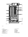
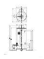
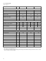
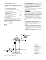
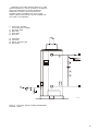
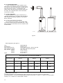
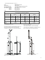
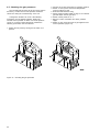
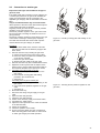
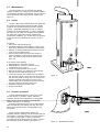
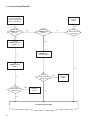
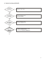
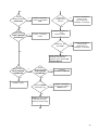
MODELS
BFM 30
BFM 50
BFM 80
INSTALLATION INSTRUCTIONS AND
USERS MANUAL
UNITED KINGDOM
CLOSED COMBUSTION WATER HEATER
INTRODUCTION
Read the installation instructions before installing the water heater. Read the user-instructions before lighting the water
heater. If these instructions are not followed carefully, this may lead to explosion and/or fire and can cause material
damages and/or physical harm.
Installation and commissioning should be carried out by a registered installer. The type of gas and standard values
which the water heater (from factory) is set on, are stated on the type plate.
The BFM-models fall under the instrument category; C13/C33. These water heaters are provided with an ignition system.
A. O. SMITH DOES NOT ACCEPT ANY RESPONSIBILITY FOR GUARANTEE, SERVICE PROVISION AND/OR PRODUCT
LIABILITY IN CASE OF UNAUTHORISED PRODUCT MODIFICATION OR REPAIRS.
2
CONTENTS
PAGE
1.
1.1
1.2
1.2.1
1.2.2
1.2.3
1.2.4
1.2.5
1.3
1.3.1
1.3.2
GENERAL
Water heater description ..................................................................................................................... 5
Technical safety equipment ................................................................................................................ 6
Gas control .......................................................................................................................................... 6
Control box ........................................................................................................................................... 6
Burner automat ................................................................................................................................... .6
Air proving switch ................................................................................................................................. 6
Gas control valve ................................................................................................................................. 6
Technical description .......................................................................................................................... 8
Measurements .................................................................................................................................... 8
Technical data ................................................................................................................................... 10
2.
2.1
2.1.1
2.1.2
2.1.3
2.1.4
2.1.5
2.1.6
2.2
2.2.1
2.2.2
2.2.3
2.3
2.4
2.5
2.6
2.7
2.8
2.9
2.10
2.11
FOR THE INSTALLER
Installation instructions ..................................................................................................................... 11
Installation ......................................................................................................................................... 11
Water connection ............................................................................................................................... 11
Condensation drain ........................................................................................................................... 14
Gas connection ................................................................................................................................. 14
Flue connection (concentric) ............................................................................................................. 14
Electrical connection ......................................................................................................................... 16
Turning the water heater on .............................................................................................................. 19
Filling the water heater ..................................................................................................................... .19
Turning the water heater on .............................................................................................................. 19
Setting up the pilot flame ................................................................................................................... 19
Turning the water heater off ............................................................................................................... 19
Usage/temperature control ............................................................................................................... 19
Checking the gas pressures ............................................................................................................ 20
Conversion to another gas ................................................................................................................ 21
Maintenance ...................................................................................................................................... 22
Anode ................................................................................................................................................. 22
Descale procedure ............................................................................................................................ 22
Condensation .................................................................................................................................... 23
Spare parts ........................................................................................................................................ 23
3.
3.1
3.1.1
3.1.2
3.1.3
3.2
3.3
3.4
FOR THE USER
Instructions for use ............................................................................................................................ 24
Warning ............................................................................................................................................. 24
Filling the water heater ...................................................................................................................... 24
Turning the water heater on .............................................................................................................. 24
Usage ................................................................................................................................................ 24
Turning the water heater off ............................................................................................................... 24
Maintenance ...................................................................................................................................... 24
4.
4.1
4.2
4.3
FAULT FINDING AND CORRECTION
Fault finding userl .............................................................................................................................. 25
Fault finding installer ......................................................................................................................... 26
Detailed fault finding installer ............................................................................................................ 27
5.
5.1
5.2
5.3
5.4
5.5
5.6
5.7
WARRANTY
Guarantee in general ........................................................................................................................ 31
Guarantee of the tank ........................................................................................................................ 31
Conditions for installation and use ................................................................................................... 31
Exclusions ......................................................................................................................................... 31
Range of the guarantee ..................................................................................................................... 31
Claims ............................................................................................................................................... 31
No other guarantee or warranty either expressed or implied is
made on behalf of A.O. Smith Water Products Company ................................................................. 31
3
Figure 1
1) TOP-BOX
2) AIR PROVING SWITCH
3) TEMPERATURE REGULATOR
ON/OFF SWITCH
RESET-KNOB
4) BURNER CONTROLLER
5) GAS VALVE
6) MANIFOLD / INJECTORS
7) PILOT BURNER
8) HORIZONTAL AIR INLET
4
9)
10)
11)
12)
13)
14)
15)
16)
17)
VENTILATION FAN
ANODE
FLUE TUBES
FLUE BAFFLE
DIAPHRAGM
INSULATION
BURNER
AIR DIFFUSION PLATE
CONDENSATE DRAIN
1. GENERAL
1.1 Description of the appliance
Construction and fitting out of the storage appliance
comply with the European Standard for gas fired hot
water storage appliances for sanitary use (EN89). The
appliance thereby satisfies the requirements of the
European Directive for Gas Appliances, and is therefore
entitled to bear the CE mark.
The BFM appliance is an enclosed appliance with a
fan in the air inlet ( appliance category C13 or C33 ). The
appliance is designed for a concentric flue
configuration. A diaphragm, across which the pressure
difference can be measured, is fitted in the air inlet
system. When the control thermostat calls for heat, the
burner control unit carries out a zero position check. The
fan is subsequently switched on and, at a signal from
the pressure difference switch, the pre-ventilation
period (minimally 30 seconds) commences. Following
the pre-ventilation period the burner control unit
switches on the ignition transformer whereby the first
gas valve (the pilot) opens. On receiving an ionisation
signal from the ignition burner, the second (main
burner) gas valve opens. The appliance is now in
operation.
Technically this appliance falls into gas category
II2L3P; the appliance is therefore suitable for natural
gas as well as propane and butane gases. The storage
appliance is suitable for working pressures to 8 bar. A
connection is provided for the optional fitting of an extra
safety feature, the temperature and pressure valve. The
interior of the tank is enamelled for corrosion protection,
and a number of magnesium anodes are fitted to the
tank for the same purpose.
A thick polyurethane insulating layer between the tank
and its steel casing prevents unnecessary heat loss. If
the storage appliance is completely filled with water it is
under continual mains pressure. When hot water is
tapped off the appliance, cold water is immediately
introduced. Turbulence strips are placed in the fire tubes for the efficient transfer of heat. The flue gases pass
their heat to the water by conduction and radiation. The
flue gases are led to the flue via the top box. The burner
bed consists of a number of bar burners. An injector is
screwed into the manifold ahead of each burner, which
ensures correct mixing of gas and primary air through
injection into the burner inlet venturi. Secondary air is
drawn between the bar burners. An air distribution plate,
which also functions as a radiant heat shield, is fitted
below the burners. Any condensation water produced is
captured beneath the combustion chamber and led
away via a siphon (see illustration 1).
5
1.2 Technical safety equipment
1.2.1 Gas control
The water heaters are equipped with a gas control
valve which regulates the flow of gas to the burner. The
combination gas control is equipped with a safety valve,
gas control valve, pilot safety valve and burner control
(on a standard natural gas setting)
1.2.2 Control box
For safety purposes, water heaters are always fitted
with three thermostats: a control thermostat, a high-limit
thermostat and an overheat thermostat.
The desired water temperature is set with the control
thermostat. To protect against freezing, the control
thermostat is also fitted with frost protection which
ignites the burner when the water temperature drops to
20oC, irrespective of the thermostat’s temperature
setting. The overheat thermostat prevents the water
reaching too high a temperature.
Should both control and high-limit thermostats
malfunction, the overheat thermostat will automatically
shut down the water heater.
The control thermostat can be set at settings 1-4
(approx. 40°C to 73°C). The frost protection ignites the
burner if the water temperature drops below 20°C. The
switch temperature of the high-limit thermostat is 84°C;
the overheat thermostat cuts in at 93°C. The sensor for
the control/frost thermostat is located at the level of the
control switch; the sensors for the high-limit and
overheat thermostats are located near the top of the
water heater.
The control box is fitted with an ON/OFF switch (I/0).
At setting I, the gas control operates on the basis of heat
demand from the control thermostat. At setting 0 the
water heater is switched off. The burner will only ignite
on the basis of heat demand from the frost protection.
When the control thermostat calls for heat, the water
heater checks all controls are in the off position. Power
is then switched to the ventilation fan. Immediately the
air pressure switch opens. The purge cycle starts. This
runs for between 30 and 60 seconds after which the
safety valve opens and the spark generator is operated.
Gas flows to the pilot burner where it is ignited by the
spark generator. The ionization probe now detects the
flame, switches off power to the spark generator and
opens the main gas valve.A softlite staged ignition
control prevents explosive ignition by allowing a small
percentage of total gas rate into the combustion
chamber initially followed by the full rate when
combustion is established. When the water temperature
reaches the set point the water heater is turned off.
If the flame extinguishes whilst in operation both the
safety (pilot) valve and the gas valve will close
immediately. If the control thermostat is still calling for
heat the burner automation will repeat the ignition
procedure.
- If no flame is detected within the safety time of
50 seconds, the burner automation will interlock and
the reset knob will light up.
- As long as the air proving switch does not operate
(remains closed), the burner automation will remain
in the waiting position, while the ventilation fan
6
continues to work.
- An interlocking of the burner automation can be
cancelled out by pressing the reset knob. If the
procedure does not succeed immediately, wait at
least 15 seconds before pressing the interlocking
knob again.
If the flame detection falls out during normal
operation, the burner automation will automatically
repeat its ignition procedure. As long as a flame is
detected within the safety period of 50 seconds, the
automation will continue to repeat the ignition procedure.
As soon as the water temperature has reached the
set value, the burner automation will close the gas
valves.
The control column has a potential-free contact for
external error message.
1.2.3. Ventilation fan
The ventilation fan is installed in the top-box. When
heat is required the ventilation fan is switched on by the
burner automation. The fan switches off when the main
burner has extinguished. The fan can be removed from
the top box via the access panel.
1.2.4 Air proving switch
The air proving switch ensures that there is sufficient
air flow for the safe operation of the water heater. If the
airflow falls below the preset value this will be detected
by the air proving switch and the gas supply to both the
ignition and main burners will be closed. The air proving
switch is preset and cannot be adjusted.
Air proving switches BFM-units
Unit
Pstart
Poff
(Pa)
(Pa)
BFM 30
250
220
BFM 50
250
220
BFM 80
230
205
The air proving switch must always be fitted with the
connection points downwards!
The air pressure differential switch must always be fitted
with the connection points at the bottom, while the pipe
with the letter H must be connected to the point P1. Pipe
L goes to connection P2.
1.2.5 Gas control
The water heaters are provided with a gas valve that
regulates the gas supply to the burners.
The gas control has a safety valve and a gas valve
and hence has a B/D-configuration. The position of both
valves can be regulated by the burner automation. To
ensure improved ignition the gas control valve opening
mechanism is fitted with a delay (softlite).
Figure 2 - Positioning ventilation
Figure 3 - Differential pressure switch
7
1.3 Technical description
1.3.1 Measurements
See figure 4
Size
BFM 30
BFM 50
BFM 80
A
1995
1995
2020
B
1795
1795
1820
C
600
600
600
D
520
520
525
E
600
600
590
F
1640
1640
1655
G
1360
1360
1360
H
630
630
625
K
710
710
710
L
1000
1000
1000
M
755
755
755
N
80/125
100/150
130/200
1
Cold water inletRP1½
2
Hot water outletRP 1½
3
Gas valve RP ¾
4
Drain valve ¾"-14 NPT
5
T&P-connection (temperature- and pressure valve) 1"-14 NPT
All dimensions in mm, rounded up to the nearest 5 mm.
8
IM D -0 05 7-R 0
Figure 4
9
1.3.2 Technical data
Heater category:II
2H3+
Description
Unit
BFM 30
BFM 50
BFM 80
Nominal gas inlet pressure
mbar
20
20
20
Burner pressure
mbar
12.5
12.5
12.5
Input
kW
29
47
75
Output to water
kW
27
42
68
Gas consumption*
m3/h
3.0
4.7
7.9
Diameter main injector
mm
2.60
2.50
2.70
Diameter injector ignition burner
mm
0.56 / 0.41
0.56 / 0.41
0.56 / 0.41
Heating time ∆T=45°C
min
35
25
12
DATA NATURAL GAS G 20
DATA PROPANE/BUTANE G 30 - G 31
G30
G31
G30
G31
G30
G31
mbar
30
37
30
37
30
37
Input
kW
29
28
46
44
75
71
Gas consumption
kg/h
2.3
2.1
3.6
3.3
5.8
5.3
Diameter main injector
mm
1.45
1.40
1.50
Diameter injector ignition burner
mm
0.25
0.25
0.25
Nominal gas inlet pressure
GENERAL
Storage capacity
litre
309
298
253
Number of bar burners
-
3
5
Number of anodes
-
2
2
4
Number of flue tubes
-
5
7
16
Water connections
-
Rp11/2
Rp11/2
Rp11/2
Gas connection
-
Rp3/4
Rp3/4
Rp3/4
Drain connection
-
3/4" - 14 NPT
3/4" - 14 NPT
3/4" - 14 NPT
Anode
-
3/4" - 14 NPT
3/4" - 14 NPT
3/4" - 14 NPT
Connection T&P-plug**
-
1” - 14 NPT
1” - 14 NPT
1” - 14 NPT
Maximum working heat
bar
8
8
Empty weight
kg
270
290
7
8
350
* Gas usage at 1013,25 mbar and 15 °C.
** For a leak-tight connection European coupling pieces with pipe screw-thread according to ISO 228/1 or ISO 7/1 can be
used on the NPT-connection nipples.
10
2. FOR THE INSTALLER
2.1.2 Water connections
If possible, use a trolley or fork-lift truck to move the
water heater. Always move the water heater in an upright
position.
2.1
Installation instructions
The following distances should be observed:
- Sides of the water heater:
(free space for the accessibility of the
hand holes)
- Rear of the water heater:
- Around top-box and concentric pipe:
- Front of the water heater:
(free space to take out bar burners)
100 cm
15 cm
15 cm
100 cm
2.1.1 Installation
Installation should be carried out in accordance with
all local authority and building regulations, local water
authority and fire regulations and the following British
standards: British Gas Publication UP1 and UP2.
BS 5482
part 1 1979
part 2 1979
part 3 1979
BS 6644
BS 6700
BS 6798
A.O. Smith water heaters are suitable for connection
to vented, unvented and pumped pressurised systems.
In each case appropriate valves and fittings should be
used to ensure the system complies with the
requirements of the water by laws, and appropriate
building regulations.
When fitting it is essential the rules of 'good practice'
are applied at all stages of installation.
Vented systems
If the water heater is to be connected to a cold feed
tank or cistern the hot water supply pipe must include an
open vent which discharges over the cold feed cistern.
The cold feed cistern must have an actual capacity of
greater volume than the hourly recovery rate of the water
heater(s) which it supplies.The minimum actual
capacity is 50 gallons or 227 litres. See diagram 5.
A.O. Smith water heaters are tested to a maximum
pressure of 12 bar and a maximum working pressure of
8 bar.
Dead legs on a hot water installation are
undesireable. Where possible they should be avoided.
Where the inclusion on the system of a dead leg is
unavoidable the following restrictions should be
applied:
- for pipes not exceeding 19 mm. inside diameter;
maximum lengh of dead leg permitted 12.0 metres;
- for pipes exceeding 19 mm. but not exceeding 25
mm. inside diameter; maximum length of dead leg
7.5 metres;
- for pipes with an inside diameter exceeding 25 mm.
maximum dead leg 3.0 metres.
IM D -0 06 5
1)
2)
3)
4)
5)
6)
7)
Gas cock
Stop valve
Three way vent valve
T&P valve
Non-return valve
Circulation pump
Drain valve
A)
B)
C)
D)
E)
Gas supply
Hot Water
Cold Water
Overflow
Return circulation
Diagram 5 - Typical UK vented system
11
Depending on the length and insulation of the water
piping and the water demand frequency, it may be
necessary to install a circulation system on the drain
cock. The return pipe of the circulation piping can be
fitted on the top of the drain cock after the sealing plug
has been removed (see figure 6).
Unvented
To install an A.O. Smith water heater on an unvented
cold water supply system a kit of valves and fittings
listed by the water research centre and complying with
part G3 of the current building regulations and BS 7206
should be used. Installation should be carried out
generally as shown on diagram 7. Kits are available
from A.O. Smith or our distributors.
1)
2)
3)
4)
5)
6)
7)
8)
9)
Gas cock
Stop valve
Expansion vessel
T&P valve
Non-return valve
Circulation pump
Drain valve
Pressure limiting valve
Expansion valve
A)
B)
C)
D)
E)
Gas supply
Hot water
Cold water
Hot water supply
Return circulation
Figure 6
IM D -0 06 6-R 0
Diagram 7 - Connection diagram (unvented system)
12
Depending on the water demand pattern (e.g., small
amounts frequently), it may be necessary to circulate the
water in the water heater to prevent temperature
stratification. Therefore, we recommend that a
circulation system is installed in the event of such
demand patterns (see figure 8). Kits are available from
A.O. Smith or our distributors.
1) Pump (type: Grundfos
UP 20-15 N150, or similar)
2) Non-return valve
3) Gate valve
4) Drain valve
5) Gas valve
A)
B)
C)
D)
Cold Water
Hot Water
Return circulation pipe
Gas supply
IM D -0 05 9
Figure 8 - Connection diagram including destratification
circulation system
13
2.1.3 Condensation drain
In order to guarantee the correct operation of the
water heater, the condensate drain of the water heater
must open into the sewer interrupted, provided with an
extra stench trap or siphon. A condensation drain
section fixed to the water heater should be fitted under
the slope. The condensate drain of the water heater
must never be sealed.
2.1.4 Gas connection
The gas installation may only be carried out by a
registered installer and in accordance with the relevant
local authority and building regulations and followint
British standards.
2.1.5 Flue connections (concentric)
The combined flue discharge and air intake tubes
(concentric) should always be assembled with a rising
slope towards the flue terminal, and in accordance with
the table below.
IM D -0 06 0
figure 9
- Wall configuration (see figure 9)
Type:
Manufacturer:
Pipe material flue tube:
Pipe material air supply:
Pipe diameter BFM 30:
BFM 50:
BFM 80:
Angle:
M2000 MDV SE
Meulink & Grol
Thick-walled aluminium with lip ring seal.
Thin-walled galvanised steel plate.
Ø 80 / 125 mm
Ø 100 / 150 mm
Ø 130 / 200 mm
90° (2 max.)
Flue configuration / horizonal discharge BFM-unit
Measurement
BFM 30
BFM 50
BFM 80
min.
max.
min.
max.
min.
max.
A
0
7000
0
7000
0
7000
B
0
7000
0
7000
0
7000
A+B
< 7000
< 7000
< 7000
All measurements are in mm.
The following applies for the horizontal pipe: slope of at least 5 mm per metre of pipe to the water heater.
NB. Measurements A + B are the total permissible dimensions of the flue, i.e. when A = 1 metre, B = 6 metres (total 7
metres) or A = 4 metres, B = 3 metres (total 7 metres).
14
- Roof discharge (see figures 10 and 11).
Type:
Manufacturer:
Pipe material flue tube:
Pipe material air supply:
Pipe diameter BFM 30:
BFM 50:
BFM 80:
Angle:
M2000 DDV SE HR/VR
Meulink & Grol
Thick-walled aluminium with lip ring seal.
Thin-walled galvanised steel plate.
Ø 80 / 125 mm
Ø 100 / 150 mm
Ø 130 / 200 mm
45°/90° (max 2)
Flue configurations roof discharge BFM-unit
Measurement
BFM 30
BFM 50
BFM 80
min.
max.
min.
max.
min.
max.
A
0
7000
0
7000
0
7000
B
0
7000
0
7000
0
7000
A+B
< 7000
< 7000
< 7000
All measurements are in mm.
these flue configurations.
These will each equate to 1 metre of flue length.
The following applies for the horizontal pipe: slope of at
least 5 mm per metre of pipe to the water heater.
A maximum of 2 bends (45° or 90°) may be used with
The maximum flue configuration is therefore 7000 mm
pipe, 2 bends (45°/90°) and a lead-through set.
IM D -0 06 1
IM D -0 06 2
Figure 10 and 11 - Roof discharge.
15
2.1.6 Electrical connection
All electrical connections must be carried out by a
registered electrical contractor to the relevant
regulations.
The BFM must be connected to a supply voltage by
means of a permanent electric connection and have a
feeder cable not less than 3 x 1,0 mm².
Supply voltage
220/240 VAC
Supply network
frequency
50 Hz
Mínimum fuse
required
1A
The electrical diagram of the BFM-heater and the
connections in the control-column are shown in figures
12 and 13.
Electrical connection diagram BFM
(see figure 12)
A) Jacket
B) Transformer 230V/238V/2VA
C) Air proving switch
D) EMC single phase filter
E) RESET knob
F) Thermostat frost
G) Thermostat regulation
H) Switch ON/OFF
K) Thermostat overheat 93°C
L) Thermostat high limit 84°C
M) Automatic burner controller
N) Plastic connector strip
P) Earth terminal block
S) Relais
Colour-code cables:
1 Blue
2 Brown
3 Yellow/green
4 Red
5 White
6 White/orange
7 White/violet
8 Black
9 Black/green
10 Black/red
11 Black/white
16
IM D 0 05 5 R 1
Figure 12 - Electrical connection diagram BFM
17
IM D -0 06 3
Figure 13 - Connection diagram control-column.
D)
E)
F)
G)
H)
K)
L)
18
Transformer 230
Air proving switch
EMC single phase filter
RESET knob
Thermostat frost
Thermostat regulation
Switch ON/OFF
M)
N)
P)
R)
X)
Y)
Thermostat overheat
Thermostat high limit
Automatic burner controller
Relay
Plastic connector strip
Earth terminal block
2.2 Turning the water heater on
2.2.1 Filling the water heater
1. Assemble the drain-off tap and check that it is closed.
2. Open the cold water tap to the water heater and open
all taps on hot water outlet points to vent them. The
heater is filled as soon as cold water pours out of
all outlet points.
3. Close all taps at hot water draining points. The
heater is now under water supply pressure. At
this pressure, the relief valve if fitted may not release
water.
2.2.2 Turning the water heater on
1. Check whether the water heater is filled with water
and whether the gas pipe to the water heater is open.
2. Vent the gas pipe by opening the pressure gauge
nipple at the inlet side of the gas valve. Close the
pressure gauge nipple as soon as the gas pipe has
been vented.
3. Turn the temperature control knob fully to the left.
4. Turn on- the supply voltage by turning the main
switch. NOTE: if the frost-thermostat is calling for heat
the burner automation will immediately start its
ignition procedure.
5. Turn the ‘I/O’-switch on the column to the ‘T’
position. The control lamp in the switch will light.
6. Turn the temperature control switch to the desired
position, preferably position 3 (approximately 60°C).
The burner will ignite; the water heater will now work
automatically.
7. Check the standing pressure with a manometer
which can be connected to the pressure gauge
nipple. Check that the working pressure is set to the
correct level (see table page 10).
The position of the temperature control knob
coincides with the following temperatures:
Position 1 = app. 40°C
Position 2 = app. 50°C
Position 3 = app. 60°C
Position 4 = app. 70°C
At high temperatures, more calcium precipitation is
caused in the water heater. Moreover, the standbylosses of the water heater are greater with higher
temperatures. It is recommended to set the controlthermostat at approximately 60°C. For reasons of
security, the water heater is provided with a high limit
and safety thermostats. The high limit thermostat is an
extra control set at 80°C and will operate in the event of
excess temperature within the water heater.
If the safety thermostat operates, the ‘RESET’ button
must be pressed after the water has cooled down. The
water heater will operate again in the usual manner.
2.2.3 Setting up the pilot flame
The pilot flame has been adjusted in the factory and
does not have to be checked.
2.3 Turning the water heater off
For short periods:
1. Turn the temperature knob fully to the left and turn the
‘I/O’-switch in the ‘O’-position.
For longer periods:
1. Switch off the supply voltage.
2. Close the gas tap in the supply line.
3. Close the water supply tap.
4. If there is danger of frost, drain the water heater.
2.4 Usage/temperature control
The water temperature is controlled via the
temperature regulator. If the temperature in the water
heater falls below the set value, the temperature
regulator will call for heat. The burner automation will
operate firstly the ventilation fan for its purge cycle, then
a spark will ignite the pilot burner. The softlite control
then ignites the main burner.
19
2.5 Checking the gas pressures
The nominal load has been set at the correct value in
the factory. A further check of the pressure should be
carried out during the commissioning of the unit.
A dangerous situation can occur if the following
instructions are not followed carefully. Setting the
nominal load is possible as there is a burner pressure
control. If you wish to adjust the burner pressure the
following procedures must be followed:
1. Switch off main power by turning the I/O switch to ‘0’
position.
Figure 14 - Checking the gas pressures
20
2. Connect the U-tube manometer to pressure nipple B.
3. Switch on main power and ensure temperature
control is calling for heat.
4. Wait until water heater is firing.
5. Check pressure against table on page 10 for relevant
gas and adjust at main gas valve.
6. Switch of main power as no. Y.
7. Remove U-tube manometer and close pressure
nipple.
8. Switch on main power and test for gas tightness and
correct operation, (Figure 14).
2.6
Conversion to another gas
Important: Install a gas valve suitable for the type of
gas to be used.
If the water heater has to function on a gas category (LP
or natural gas) other than the gas set as standard (ex
works), the water heater must be converted to the
applicable gas category with the associated conversion
kit(s).
Only an accredited installer may convert the heater.
All the injectors of the main burner bars and the injector
of the ignition pilot must be replaced.
Regurlary natural gas units do have a burner pressure
regulator, but LP-gas units do not.
The burner pressure regulator on the gas control must
be removed when converting the heater for use on LPgas (if present).
The burner pressure regulator must be fitted on the gas
control when converting to natural gas (if required)
The table with technical data shows which injectors
must be fitted for the gas category in question.
Procedure:
1. Shut the water heater down; close the main inlet
gas valve and switch of the electricity supply at the
main switch;
2. Remove the burner tray including the gas valve:
a. remove the screws of the burner tray housing,
b. loosen the wiring of ingition and ionisation pen
on the burner controller,
c. loosen the gas control cable,
d. dismount the gas supply to the gas valve;
3. Remove the burner tray from underneath the heater;
4. Replace the main injectors and the injector of the
ignition burner. Use the table with technical data to
check that the diameter of the injectors is correct;
5. Converting from natural gas to LP-gas:
a. remove the burner pressure regulator on the
gas control,
b. mount the flat covering plate with sealing
provided in the conversion kit,
c. see figure 15;
Converting from LP-gas to natural gas:
a. remove the flat covering plate with sealing on the
gas control,
b. mount the burner pressure regulator on the gas
valve,
c. See figure 16;
6. Mount the burner tray;
7. Reconnect the wiring and gas supply to the gas
valve;
8. Open the main inlet gasvalve;
9. Check the gas inlet pressure;
10. Switch on the electricity supply at the main switch;
11. Commision the water heater;
12. Adjust the burner pressure to the value as indicated
in the technical data;
13. Check the soundness;
14. Check the operation of the heater;
15. Fix the conversion sticker from the conversion kit
below the rating plate to the heater, so that is clear
on which gas category the heater operates.
A O S 05 4 6
Figure 15 - mounting covering plate with sealing on the
gas valve
A O S 54 7
Figure 16 - mounting burner pressure regulator on the
gas valve,
21
2.7
Maintenance
The water heater must be checked and cleaned
regularly (at least once a year) by an accredited installer,
so that proper operation is guaranteed. The bar burners,
control and safety valves must also be checked. (see
figure 17).
2.8
Anode
The life of the anode is determined by the quality and
the quantity of water flowing through the water heater.
Therefore, we recommend that the anode is checked
regularly - preferably simultaneously with an internal
inspection of the enamelled tank. In order to determine
the frequency with which the anodes must be replaced,
the water side of the boiler must be checked three
months after installation. The anodes must be replaced
if more than 50% has dissolved at any point on their
length.
Procedure:
1. Shut off the cold water supply tap.
2. Completely empty the water heater by means of the
draw-off tap. Remember to ventilate the water heater.
3. Remove the sealing plates at the hand holes on the
outer cover of the water heater.
4. Open the hand holes and inspect the anodes. In
order to guarantee a water-tight seal at the hand
holes, the rubber O-rings must be replaced (see
figure 18).
If the anodes need replacing:
1. Disassemble the concentric flue tube.
2. Disassemble the electrical connection of the
ventilation fan on the top-box.
3. Loosen the fastening bolts of the top-box.
4. Remove the top-box, the positioning of the anodes
will now become visible (see figure 18).
5. Loosen the anodes with suitable tools and replace
with new ones. NOTE: the anodes must be in contact
with the tank (metal on metal). For if the anodes and
tank are electrically separated (as a result of the
sealant used), the anode cannot perform its function.
This can shorten the life-span of the tank.
6. Assemble everything in reverse order.
7. Fill the water heater.
2.9
Figure 17
Descale procedure
Calcium deposition depends on the type of water
and the demand. In addition, calcium deposition
increases at high water temperatures. A temperature
setting of 60°C is recommended, which will keep
calcium deposition to a minimum.
Inspection hatches are located on the right and left
sides for inspecting and deliming the tank. The hand
holes can be reached via the covering plates on the
outer jacket.
Empty the water heater before opening the
inspection hatches. Deliming must be executed with the
correct tools. Consult the supplier of the water heater or
the installer on this matter. In order to guarantee a
water-tight seal of the hand holes, the rubber O-rings in
the hand holes must be replaced (see figure 17).
22
Figure 18 - Maintenance anodes
2.10 Condensation
If the water heater has been filled with cold water or if
the hot water usage has been very high, normally
condensation of the flue gasses will occur on the cold
sides of the combustion chamber and the flue tubes.
The water drops will fall on to the burner bed which can
cause a hissing sound. This is normal and will
disappear as soon as the water heater has reached its
operating temperature again.
2.11 Spare parts
To order spare parts, it is important to state the water
heater type, model and the complete serial number.
Figure 19 - Maintenance anodes
23
3. FOR THE USER
3.3
3.1. Instructions for use
For short periods:
1. Turn the temperature knob fully to the left and turn
the ‘I/O’-switch in the ‘O’-position.
Installation and commissioning of the water heater
should only be undertaken by a registered installer.
3.1.2 Filling the water heater
1. Assemble the drain-off tap and ensure it is closed;
2. Open the cold water tap to the water heater and open
all taps on hot water drain-off points to vent them.
The heater is filled as soon as cold water pours out of
all drain-off points;
3. Close all taps at hot water drain-off points. The
heater is now under water supply pressure. At this
pressure, the relief valve if fitted may not release
water.
3.1.3 Turning the water heater on
1. Check that the water heater is filled with water and
that the gas pipe to the water heater is open;
2. Turn the temperature control knob fully to the leftl;
3. Turn on( the supply voltage by turning the main
switch. NOTE: if the frost-thermostat has been
turned on, the burner automation will immediately
start its ignition procedure);
4. Turn the ‘I/O’-switch on the column in the ‘T’ position.
The control lamp in the switch will now light;
5. Turn the temperature control switch in the desired
position, preferably position 3 (approximately 60°C).
The ventilation fan will start. the water heater will
ignite and work automatically.
3.2
Usage
The water temperature is controlled via the
temperature regulator. If the temperature in the water
heater falls below the set value, the temperature
regulator call for heat. The burner automation will
operate firstly the ventilation fan for its purge cycle, then
a spark will ignite the pilot burner. The softlite control
then ignites the main burner.
The temperature is indicated by the position of the
temperature dial:
Position 1 = app. 40°C
Position 2 = app. 50°C
Position 3 = app. 60°C
Position 4 = app. 70°C
At high temperatures, more calcium precipitation is
caused in the water heater. Moreover, the standbylosses of the water heater are greater at higher
temperatures. It is recommended that the controlthermostat be set at approximately 60°C. For reasons of
security, the water heater is provided with a high limit
and safety thermostats. If the high limit thermostat
operates, the burner will not fire until the water has
cooled sufficiently to allow the thermostat to
automatically reset. The water heater will then return to
the control of the temperature regulator.
If the safety thermostat operates due to high
temperature the ignition sequence must be repeated
after resetting the control.
24
Turning the water heater off
For longer periods:
1. Switch off the supply voltage;
2. Close the gas tap in the supply line;
3. Close the water supply tap;
4. If there is danger of frost, drain the water heater.
3.4. Maintenance
The water heater must be checked and cleaned
regularly (at least once a year) by an accredited installer,
so that proper operation is guaranteed. The bar burners,
the pilot burner and the control and safety valves must
also be checked.
4. FAULT FINDING
4.1
Fault finding USER
No or insufficient
hot water.
Check whether the
electricity
is turned on.
Reduce the water use
or increase the
control thermostat.
Check whether the
gas supply is turned
on.
yes
yes
Does the
ON/OFF switch light
up?
yes
Does the
RESETswitch light
up?
yes
no
Check if
ON/OFF switch in
position 1?
Push RESET switch up
to three times
yes
no
no
Is the
water heater in
operation?
Put
ON/OFF switch in
position 1?
Is the
water heater in
operation?
Is the
water heater in
operation?
yes
Problem
solved
yes
Problem
solved
no
no
Consult your installer.
25
4.2 Fault finding INSTALLER
Check gas connection
and the electricity
supply make sure that
they are switched on.
Problem
solved
yes
Does the
ON/OFF switch
light up?
Does the
RESET switch
light up?
yes
Is the
water heater in
operation?
no
no
yes
Check if
ON/OFF switch is in
position 1?
Push the
RESET button
up to three times
no
Put
ON/OFF switch in
position 1.
no
Is the
water heater in
operation?
no
Is the
water heater in
operation?
yes
Problem
solved
no
no
See detailed fault finding
26
yes
Problem
solved
4.3 Detailed fault finding INSTALLER
Check
voltage present
at connection 1.
no
Reinstate voltage supply
yes
Check
voltage present
after FILTER
no
Ensure connections correct,
if yes replace FILTER
no
Ensure connections correct,
if yes replace ON/OFF switch
no
1. Check if controle thermostat is closed
2. Ensure connections correct.
3. If yes replace CONTROL THERMOSTAT.
yes
Check
voltage present at
gate 3 ON/OFF
switch
yes
Check
voltage present
at gate 11 and 12
CONTROL
THERMOSTAT.
yes
27
yes
Check
voltage present at
GATE 12 MAXIMUM
THERMOSTAT?
no
Ensure connections correct,
if yes replace
MAXIMUM THERMOSTAT
yes
Check
voltage present at
GATE 1 BURNER
AUTOMATION
S4560D 1150?
no
Ensure connections correct,
if yes replace
BURNER AUTOMATION
no
Replace
BURNER AUTOMATION
no
Ensure connections correct,
if yes replace
VENTILATING FAN
yes
Check
voltage present at
GATE 8 BURNER
AUTOMATION
yes
Is VENTILATING FAN
in operation?
yes
Check
voltage present at
GATE 7, BURNER
AUTOMATION
no
Check
voltage present at
GATE 3 AIR PROVING
SWITCH
yes
no
Check
voltage present at
GATE 1 AIR PROVING
SWITCH
yes
yes
Ensure connections correct
DISCONNECT
GAS SUPPLY
yes
Check
voltage present at
GATE 7, BURNER
AUTOMATION
yes
28
no
Replace
BURNER AUTOMATION
Disconnect the pipe air
supply by removing the
elbow at the rear bottom.
Measure pressure at
hose H
at the column.
no
Ensure connections
correct,
if yes replace
BURNER
AUTOMATION
yes
Check
voltage present at
GATE 12 ECO
no
Pressure
H higher then
300 PA?
Ensure connections
correct, if yes replace
ECO
Ensure connections
correct, if yes
check hose H for
leakkage or blockings
yes
yes
Check
voltage present at
GATE 11 BURNER
AUTOMATION
no
no
Measure pressure at
hose
H at the column
Ensure connections
correct
Pressure L less
then 0 PA?
no
Ensure connections
correct, if yes
check hose L for
leakkage or blockings
yes
yes
Check exhaust system on
blockings if the exhaust
system is open, replace AIR
PROVING SWITCH
Check
voltage present at
GATE 10 BURNER
AUTOMATION
yes
no
Check
voltage present at
GATE 2 BURNER
AUTOMATION
no
Replace
BURNER AUTOMATION
no
Ensure connections
correct, if yes replace
RESET switch
yes
Problem solved
Does the RESET
switch light up?
yes
RESET the water heater
and wait one cycle,
advanced Fault Finding
29
Water heater in
in operation?
yes
Problem
solved
no
Gas supply
present?
no
Re-instate gas supply
and reset water heater
yes
IONISATION PROBLEMS.
Carry out 3 RESET cycles to make
sure the pilot is provided with gas.
Check gasconnections towards the
pilot burner. Carry out one more
RESET cycle. If no operation is valid
replace the entire PILOT BURNER
assy. RESET water heater after
replacing the PILOT BURNER
Water heater
in operation?
yes
Problem
solved
no
Check
voltage on
PRIMARY CIRCUIT,
TRANSFORMER
Ensure connections
correct
no
Ensure connections
correct. If yes replace
transformer
yes
Check
voltage on
SECUNDARY CIRCUIT,
TRANSFORMER
yes
Problem
solved
30
no
5. WARRANTY
and laundries or where some industrial degreasing
products are used and stored (for further
information and advise please contact the
A.O. Smith Technical Department).
The following conditions form the guarantee agreement
between A.O. Smith Water Products Company (the
warrantor) and the owner of the water heater.
5.5
5.1
Guarantee in general
If within one year of the original installation date of the
water heater any part or component other than the tank
shall prove upon examination by the warrantor or
authorised agent to be defective in material or workmanship, the warrantor will exchange such part or
component.
5.2
Guarantee of the tank
If within 3 years of the original installation date, the tank
fails due to rust or corrosion from the water side, the
warrantor will supply a complete new water heater of
equivalent size and duty (excluding delivery and
installation charges). On the replacement water heater a
guarantee will be granted sufficient to cover the
unexpired portion of the original 3 year guarantee of the
originally installed water heater.
5.3
Conditions for installation and use
The guarantee applies to the water heater only while it
remains in its orignial location, and is installed in
accordance with local plumbing and building
regulations and all relevant Codes of Practice.
The water heater should also have been used only:
a) for potable water free to circulate at all times and
with the tank free of damaging scale deposits;
b) at temperatures not exceeding the maximum setting
of its thermostat and ECO (Energy Cut Off device);
c) at water pressures and/or energy inputs which do
not exceed those stated on the rating plate of the
water heater;
d) in a non corrosive atmosphere or area;
e) with an approved temperature and pressure relief
valve of adequate capacity not exceeding the
working pressure rating shown on the water heater,
and installed in conformity with A.O. Smith Water
Products Companies installation instructions;
f) when anode(s) have been inspected and renewed,
if they are worn or erroded by 50% of more at any
point of their length.
5.4
Range of the guarantee
All replacement water heaters supplied under the terms
of this warranty will be supplied ex stock on an F.O.B.
basis. A.O. Smith accepts no responsability for carriage,
labour or other installation costs.
5.6
Claims
Any claim under this warranty should be initiated with the
dealer who originally sold the water heater or with any
other dealer or stockist of the warrantors products.
5.7
No other guarantee or warranty either
expressed or implied is made on
behalf of A.O. Smith Water Products
Company.
With respect to the water heater in question further A.O.
Smith does not guarantee this water heater as suitable
for purpose except within the terms of warranty detailed
above.
A.O. Smith Water Products Company will not be liable by
virtue of this guarantee or otherwise for damage to any
persons or property when arising out of contracts or tort.
The terms of this guarantee do not effect your statutory
rights under United Kingdom Consumer Legislation.
This guarantee applies to the following models:
BFM 30
BFM 50
BFM 80
Exclusions
The guarantee will be null and void:
a) if the water heater has been damaged by an
external cause;
b) in case of misuse, neglect (including frost damage)
or incorrect use of the water heater;
c) in case of unauthorised alteration, modification or
repair;
d) in case of ingress into the water heater of
chemicals, pollutants or contaminants;
e) if the hardness of the incoming water is, or has
been, softened below 106 ppm CaCO3 ;
f) if the water heater is effected by corrosive vapours
such as those found in hairdressers, dry cleaners
31
0305 664 R0
32