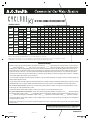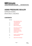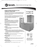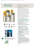
1
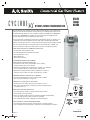
UP TO 96% THERMAL EFFICIENCY,DIRECT VENT
BTH-120
through
BTH-500
The A.O. Smith Cyclone Xi family of products represents the industry’s most technologically
advanced commercial water heaters. The innovative Cyclone Xi design takes performance to
its highest level with efficiencies of 95% and 96%. Models are available from 120,000 BTUs
and now up to 500,000 BTUs. In addition, the Cyclone Xi features an Intelligent Control
System making it the smartest water heater in the industry.
Cyclone Xi provides outstanding hot water output, with dramatic savings on operating costs
compared to units with standard 80% efficiency. A.O. Smith’s leading-edge engineering
delivers conventional power-vent or sealed combustion power direct-vent versatility, low NOx
emissions and excellent space-saving characteristics. Powered anodes, standard on all
Cyclone Xi models, provide superior tank protection for years of trouble free operation.
INTELLIGENT CONTROL SYSTEM WITH LCD DISPLAY
• Exclusive A.O. Smith designed control
• Provides detailed water heater status information
• Precise temperature control
• Built-in diagnostics
• Run histrory information
SUBMERGED COMBUSTION CHAMBER,
WITH HELICAL HEAT EXCHANGER COIL
• Positioned in center of tank, surrounded by water to virtually
eliminate radiant heat loss from chamber
• Spiral heat exchanger keeps hot burner gases swirling, uses centrifugal
force to maximize efficiency of heat transfer to water in tank
• Spiral heat exchanger prevents scale and sediment from forming on
water-side surface, which can reduce energy efficiency over time
POWERED ANODES STANDARD ON ALL MODELS
• Provides long-lasting tank protection in varying water conditions
• Does not require maintenance or inspection
PERMAGLAS® ULTRA COAT™ GLASS LINING
• Exclusive process provides superior protection against corrosion
• Both sides of heat exchanger coil are lined for protection against flue gas
condensate inside coil
MECHANICAL VENTING VERSATILITY
• Conventional power-venting or sealed combustion direct venting
• Vents vertically or through sidewall
• Direct-vent intake and exhaust pipe can terminate separately outside building,
or through single opening, using concentric vent assembly
• Uses inexpensive PVC, CPVC or ABS pipe for intake and exhaust
Approved,
Rule 1146.2 Low NOx for
California and Texas
BTH-120-250
BTH-300-500
HIGH EFFICIENCY PRE-MIX POWERED BURNER
• Down-fired pre-mix burner provides optimum efficiency and quiet operation
• Top-mounted burner position prevents condensation from affecting burner operation
Page 1 of 4
ACGSS02407
December
July
2007R 2007R
188427_ACGSS02407.indd 1
12/7/07 9:26:21 AM
UP TO 96% THERMAL EFFICIENCY,DIRECT VENT
OTHER CYCLONE Xi FEATURES
SPACE-SAVING DESIGN FOR INSTALLATION FLEXIBILITY
• Reduced footprint, ease of service, protection from water damage in case of flooding
• Easy to remove top cover for convenient access to serviceable parts
• 0˝ installation clearances on sides and rear, 2˝ installation clearance on top, 4˝ alcove installation clearance in front
of unit
• 0˝ clearance to combustibles, approved for combustible floors
FACTORY-INSTALLED TEMPERATURE AND PRESSURE RELIEF VALVE
MAXIMUM HYDROSTATIC WORKING PRESSURE: 160 PSI
HANDHOLE CLEANOUT
• Allows easy access to tank interior for cleaning
CODES AND STANDARDS
•Design-certified by UL (Underwriters Laboratories) International, according to ANSZ21.10.3-CSA4.3 standards
governing storage-type water heaters
• Meets ASHRAE/IESNA 90.1-1999• Design-certified by Underwriters Laboratories to NSF standard 5 for 180° F (62° C) water
• Meets SCAQMD Rule 1146.2 for low-NOx emissions
• ASME tank construction optional on 120 to 250 model sizes. ASME tank construction standard on 300,400 and 500 models
THREE-YEAR LIMITED TANK WARRANTY
• For complete warranty details, consult written warranty shipped with heater, or contact A. O. Smith
INSTALLATION CONSIDERATIONS
1. Condensate Drain – This is a fully condensing water heater and should be located near a drain to permit proper
disposal of condensate.
2. Vent Termination – Exhaust gases of this water heater are less than 140° F. In cold climates water vapor in flue
gases will condense into a cloud of vapor where the vent exits the building. This vapor can gradually discolor exterior
building surfaces. Vent termination should be located where this vapor cloud and potential discoloration are not a
concern. Locating vent termination 6˝ or more from the wall helps vapor from being trapped along a building’s face.
To avoid this problem, the vent can be terminated on the roof. Always locate vent termination above the maximum
snowline, and do not locate vent termination above a walkway.
3 Air Intake – In cold climates, air intake should be located at least three feet from the vent termination of the water
heater and any other appliance vents that discharge moisture-laden air (such as clothes dryers). This will help prevent
freeze-over of the intake screen required to prevent foreign objects from entering the intake pipe. Air intake should be
located above the maximum snowline.
4. Blockage Sensors – The water heater is equipped with sensors to shut it down if blockage of vent or air intake occurs.
A light on the heater’s diagnostic panel will alert service technicians to this problem.
5. Noise – Vent terminal should be located away from bedroom windows or other areas where blower noise will be
objectionable. Avoid venting into corners or confined areas, which will amplify sound. Anchoring intake or vent pipe
to walls or ceilings can cause noise to be transmitted to living areas, and isolation mounts should be used where
anchoring is required.
6 Optional Concentric Vent Kit - Helps to minimize unsightly wall/roof penetrations.
BTH-120 - 300 vent kit p/n 9003910105
BTH-400 - 500 vent kit p/n 9006144005
Page 2 of 4
ACGSS02407
188427_ACGSS02407.indd 2
12/7/07 9:26:22 AM
BTH-120-250
WATER OUTLET
1 1/2˝ NPT
A
B
D
G
C
BTH-300-500
E
F
INSTALLATION CLEARANCES
Sides
0˝
Front
0˝
Rear
0˝
Top
1.5˝
To Combustibles*
MAXIMUM EQUIVALENT
VENT LENGTH:
GAS VALVE PIPING
0˝
• Approved for combustible floors
BTH-120
1/2˝ NPT
BTH-150
3/4˝ NPT
BTH-199
3/4˝ NPT
BTH-250
3/4˝ NPT
BTH-300
1 1/4˝ NPT
BTH-400
1 1/4˝ NPT
BTH-500
1 1/2˝ NPT
BTH120 – 250
using 3˝ pipe:
50 ft.
BTH120 – 250
using 4˝ pipe:
120 ft.
BTH300 – 500
using 3˝ pipe:
not applicable
BTH300 – 500
using 4˝ pipe:
70 ft.
DIMENSIONS AND SHIPPING WEIGHTS
DIMENSIONS
MODEL
A
INCHES/CM
B
C
D
E
F
INCHES/CM INCHES/CM INCHES/CM INCHES/CM INCHES/CM
G
SHIP WEIGHT
STD
SHIP WEIGHT
ASME
INCHES/CM
LBS/KG
LBS/KG
BTH-120
55.5/141
44.5/113
35/88.9
27.75/70.5
7.5/19.1
6.3/16
47/119.4
460Lbs/208.7Kg 490Lbs/222.2Kg
BTH-150
75.5/191.8
64.5/163.8
55.5/141
27.75/70.5
7.5/19.1
6.3/16
68/172.7
555Lbs/251.7Kg 595Lbs/269.9Kg
BTH-199, 250
75.5/191.8
64.5/163.8
55.5/141
27.75/70.5
7.5/19.1
6.3/16
72/182.9
555Lbs/251.7Kg 595Lbs/269.9Kg
BTH-300, 400, 500
75.5/191.8
64.5/163.8
50.77/129 33.12/84.1
8/20.3
4.86/12.3
67.25/170.8
N/A
855Lbs/408.2 Kg
Water connections: 1-1/2˝
Page 3 of 4
ACGSS02407
188427_ACGSS02407.indd 3
12/7/07 9:26:22 AM
UP TO 96% THERMAL EFFICIENCY,DIRECT VENT
RECOVERY CAPACITY
U.S. Gallons/Hr and Litres/Hr at TEMPERATURE RISE INDICATED
MODEL
TYPE OF
GAS
NATURAL/
BTH 120
PROPANE
INPUT
BTUH
120,000
35
NATURAL/
BTH 150
PROPANE
150,000
NATURAL/
BTH 199
PROPANE
199,900
NATURAL/
BTH 250
PROPANE
250,000
NATURAL/
PROPANE
300,000
BTH 400
NATURAL/
PROPANE
399,900
BTH 500
NATURAL/
PROPANE
499,900
BTH 300
Thermal
KW Efficiency
44
58
73
88
117
146
95%
95%
95%
95%
96%
96%
95%
Fº
30 Fº
40 Fº
50 Fº
60 Fº
70 Fº
80 Fº
90 Fº
100 Fº 110 Fº 120 Fº 130 Fº 140 Fº
60 U.S. Gal
Cº
GPH
17 Cº
461
22 Cº
345
28 Cº
276
33 Cº
230
39 Cº
197
44 Cº
173
50 Cº
154
56 Cº
138
61 Cº
126
67 Cº
115
72 Cº
106
78 Cº
99
227 Litres
LPH
1744
1308
1046
872
747
654
581
523
476
436
402
374
100 U.S. Gals. GPH
576
432
345
288
247
216
192
173
157
144
133
123
LPH
2179
1635
1308
1090
934
817
726
654
594
545
503
467
100 U.S. Gals. GPH
767
575
460
384
329
288
256
230
209
192
177
164
LPH
2904
2178
1743
1452
1245
1089
968
871
792
726
670
622
100 U.S. Gals. GPH
960
720
576
480
411
360
320
288
262
240
221
206
3632
2724
2179
1816
1557
1362
1211
1044
991
908
838
778
130 U.S. Gals. GPH 1164
873
699
582
499
436
388
349
318
291
269
250
4406
3304
2644
2203
1888
1652
1469
1322
1201
1102
1017
945
130 U.S. Gals. GPH 1552
1164
931
776
665
582
517
465
423
388
359
332
5875
4406
3525
2938
2518
2203
1958
1759
1602
1469
1356
1259
130 U.S. Gals. GPH 1919
1439
1151
959
822
720
640
576
523
480
443
411
5447
4358
3631
3113
2724
2421
2179
1981
1816
1676
1556
Approx.
Capacity
379 Litres
379 Litres
379 Litres
492 Litres
492 Litres
492 Litres
LPH
LPH
LPH
LPH
7263
Recovery capacities are based on heater performance at 95% and 96% thermal efficiency.
Add "A" to model number when ordering ASME. Optional on 120 - 250 models. Standard on 300 - 500 models.
Maximum gas supply pressure for 120 - 250: 10.5" w.c. natural gas 14" w.c propane. Maximum gas supply pressure for 300-500 10" w.c. natural gas 13" w.c. propane.
Manifold pressure: 4" w.c. natural gas 10" w.c. propane. Electrical requirements: 120 VAC, Blower 2.2 Amps FL, Igniter 4.0 Amps.
SUGGESTED SPECIFICATION
(Natural or Propane) gas water heater(s) shall be A. O. Smith Cyclone Xi model # _________ or equal, with up to 96% thermal efficiency, a storage capacity of
______ gallons, an input rating of __________ BTUs per hour, a recovery rating of ___________ gallons per hour (gph) at 100° F rise and a maximum hydrostatic
working pressure of 160 PSI. Water heater(s) shall: 1. Have seamless glass-lined steel tank construction, with glass lining applied to all water-side surfaces
after the tank has been assembled and welded; 2. Have a spiral-shaped heat exchanger placed entirely inside the tank, which shall be glass-lined to protect
against acidic flue gas condensate; 3. Have foam insulation and an ASME-rated temperature and pressure relief valve; 4. Have a down-fired power burner
designed for precise mixing of air and gas for optimum efficiency, requiring no special calibration on start-up; 5. Be approved for 0˝ clearance to combustibles.
Heater shall be supplied with maintenance-free powered anode.
The control shall be an integrated solid-state temperature and ignition control device with integral diagnostics, graphic user interface, fault history display, and
shall have digital temperature readout.
The water heater(s) shall: 1. Be design-certified by UL (Underwriters Laboratories), according to ANSZ21.10 standards governingstorage-type water heaters; 2. Meet
ASHRAE/IESNA 90.1-1999; 3. Be design-certified by Underwriters Laboratories for 180° F (62° C) water; 4. Meet SCAQMD Rule 1146.2 for low-NOx emissions.
For conventional-vent specification: The BTH-120 - 250 water heater(s) shall be suitable for venting in 3˝ PVC pipe for a total equivalent distance of 50 ft
and 4˝ PVC pipe for a total equivalent distance of 120 ft.
The BTH-300 - 500 water heater(s) shall be suitable for venting only in 4˝ PVC pipe, for a total equivalent distance of 70 ft.
For sealed-combustion direct-vent specification: The BTH-120 - 250 water heater(s) shall be suitable for venting with (3˝ or 4˝) _______ diameter PVC pipe for a
total equivalent distance of (50 ft or 120 ft) ________ feet. [Alternative venting: the heater(s) shall be suitable for sealedcombustion direct venting using a (3˝ or 4˝)
________ diameter PVC exhaust pipe for a total distance of (50 ft or 120 ft) ________ equivalent feet of vent and (50 ft or 120 ft) _______ equivalent feet of intake.]
The BTH-300 - 500 water heater(s) shall be suitable for sealed combustion direct-vent using only 4˝ diameter PVC pipe and 4˝ diameter PVC exhaust pipe for a
total equivalent distance of 70 ft.
Operation of the water heater(s) in a closed system where thermal expansion has not been compensated for (with a properly sized thermal expansion tank) will
void the warranty.
For Technical Information and Automated Fax Service, call 800-527-1953.
A. O. Smith reserves the right to make product changes or improvements without prior notice.
Page 4 of 4
December
July 2007R2007R
188427_ACGSS02407.indd 4
Printed in U.S.A.
ACGSS02407
12/7/07 9:26:23 AM