1
C H A P T E R
7
Configuring QoS on an Access Point
This chapter describes how to configure quality of service (QoS) on an access point. QoS provides
preferential treatment to certain traffic at the expense of other traffic. Without QoS, the access point
offers best-effort service to each packet, regardless of the packet contents or size. It sends the packets
without any assurance of reliability, delay bounds, or throughput.
Recommended Reading
The following information is recommended for gaining a better understanding of QoS as it applies to
voice deployments in a wireless environment:
Wireless Quality-of-Service Deployment Guide
http://www.cisco.com/en/US/products/hw/wireless/ps430/prod_technical_reference09186a008014449
8.html
Cisco Wireless IP Phone 7920 Design and Deployment Guide
http://www.cisco.com/en/US/products/hw/phones/ps379/products_implementation_design_guide_boo
k09186a00802a029a.html
Understanding QoS for Wireless LANs
Typically, networks operate on a best-effort delivery basis that means that all traffic has equal priority
and an equal chance of being delivered in a timely manner. When congestion occurs, all traffic has an
equal chance of being dropped.
When QoS is configured on an access point, you can select specific network traffic, prioritize it, and use
congestion-management and congestion-avoidance techniques to provide preferential treatment.
Implementing QoS in a wireless LAN makes network performance more predictable and bandwidth
utilization more effective.
Configuring QoS creates and applies policies to the VLANs configured on the access point. If VLANs
are not used on the network, QoS policies can be applied to the Ethernet and radio ports.
QoS for Wireless LANs Versus QoS on Wired LANs
The QoS implementation for wireless LANs differs from QoS implementations on other Cisco devices.
With QoS enabled, access points perform the following:
•
Does not classify packets; it prioritizes packets based on Differentiated Services Code Point (DSCP)
value, client type (such as a wireless phone), or the priority value in the 802.1q or 802.1p tag.
Cisco Wireless Router and HWIC Configuration Guide
OL-6415-03
7-1
Chapter 7
Configuring QoS on an Access Point
Understanding QoS for Wireless LANs
•
Does not construct internal DSCP values; it only supports mapping by assigning IP DSCP,
precedence, or protocol values to Layer 2 CoS values. Table 7-1 lists the class of service (CoS)
values as they map to DSCP values.
Table 7-1
CoS Values Mapped to DSCP Values
CoS Value
DSCP Value
1
10
2
18
3
26
4
34
5
46
6
48
7
56
•
Carries out Enhanced DCF (EDCF)-like queuing on the radio egress port only.
•
Support only 802.1Q/P tagged packets. Access points do not support ISL.
•
Support only Cisco Modular QoS CLI (MQC) policy-map set cos action.
•
Prioritize the traffic from voice clients (such as Symbol phones) over traffic from other clients when
the QoS Element for Wireless Phones feature is enabled.
To contrast the wireless LAN QoS implementation with the QoS implementation on other Cisco network
devices, see the Cisco IOS Quality of Service Solutions Configuration Guide at this URL:
http://www.cisco.com/univercd/cc/td/doc/product/software/ios122/122cgcr/fqos_c/index.htm
Impact of QoS on a Wireless LAN
Wireless LAN QoS features are a subset of the proposed 802.11e draft. QoS on wireless LANs provides
prioritization of traffic from the access point over the WLAN based on traffic classification.
Just as in other media, you might not notice the effects of QoS on a lightly loaded wireless LAN. The
benefits of QoS become more obvious as the load on the wireless LAN increases, keeping the latency,
jitter, and loss for selected traffic types within an acceptable range.
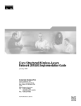
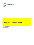
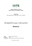
QoS on the wireless LAN focuses on downstream prioritization from the access point:
•
The radio downstream flow is traffic transmitted out the access point radio to a wireless client
device. This traffic is the main focus for QoS on a wireless LAN.
•
The radio upstream flow is traffic transmitted out the wireless client device to the access point. QoS
for wireless LANs does not affect this traffic.
•
The Ethernet downstream flow is traffic sent from a switch or a router to the Ethernet port on the
access point. If QoS is enabled on the switch or router, the switch or router might prioritize and
rate-limit traffic to the access point.
•
The Ethernet upstream flow is traffic sent from the access point Ethernet port to a switch or router
on the wired LAN. The access point does not prioritize traffic that it sends to the wired LAN based
on traffic classification.
Figure 7-1 shows the upstream and downstream traffic flow.
Cisco Wireless Router and HWIC Configuration Guide
7-2
OL-6415-03
Chapter 7
Configuring QoS on an Access Point
Configuration Guidelines
Figure 7-1
Upstream and Downstream Traffic Flow
Radio
downstream
Ethernet
downstream
Client
device
Radio
upstream
Access
point
Ethernet
upstream
81732
Wired
LAN
Precedence of QoS Settings
When you enable QoS, the access point queues packets based on the CoS value for each packet. If a
packet matches one of the filter types based on its current precedence, the packet is classified based on
the matching filter and no other filters are applied.
Table 7-2 shows the precedence of QoS filters. Precedence number zero is the highest.
Table 7-2
Precedence of QoS Filters
Precedence
Filter Type
0
Dynamicly created VoIP client filter. Traffic from voice clients takes
priority over other traffic regardless of other policy settings. This setting
takes precedence over all other policies, second only to previously
assigned packet classifications.
1
User configured class-map match clause (except match any). QoS Policies
configured for and that apply to VLANs or to the access point interfaces
are third in precedence after previously classified packets and the QoS
Element for Wireless Phones setting
2
User configured class-map match any clause (match VLAN). If a default
classification for all packets on a VLAN is set, that policy is fourth in the
precedence list.
Configuration Guidelines
Before configuring QoS on an access point, you should be aware of this information:
•
Be familiar with the traffic on your wireless LAN. If you know the applications used by wireless
client devices, the sensitivity of applications to delay, and the amount of traffic associated with the
applications, configuring QoS improves performance.
•
QoS does not create additional bandwidth on a wireless LAN; it helps control the allocation of
bandwidth. If there is enough of bandwidth on your wireless LAN, it might not be necessary to
configure QoS.
An access point is essentially a Layer 2 transparent bridge between wired and wireless networks.
Typically, bandwidth on wireless side constrains the the wired side. For example, 802.11b offers 6 Mbps
half duplex and 100baseT offers 100 Mbps full duplex.
Cisco Wireless Router and HWIC Configuration Guide
OL-6415-03
7-3
Chapter 7
Configuring QoS on an Access Point
Configuration Guidelines
In addition, a Cisco access point uses Access Control Lists for forwarding or blocking packets on
selective basis, as designated by the user for the purpose of:
•
Providing QoS for Voice-over-IP (VoIP) phones.
•
Mapping IP precedence values into 802.1P/Q Class of Service (CoS) values for downlink traffic.
•
Providing Layer 2 and Layer 3 Access Control List features to the bridging path and access point
host receive path.
802.11 VOIP Phone Support
The Symbol element is advertised by the access point. This helps a Symbol phone to make an association
decision if there are multiple access points serving the area. The current packet rate is the calculation of
average means of number of packets transmitted per second for the past 8 seconds.
After the normal 802.11 association process, a Symbol phone sends a proprietary Symbol 802.11 phone
registration message (WNMP) to the access point to complete the association.
The Symbol phone does not associate to an access point if the advertised packet rate is above the
threshold of the access point. The Symbol phone uses its Symbol Element as optional information. Basic
operation does not require an access point to send Symbol Elements.
Mapping IP Precedence Examples
The QoS examples in this section show the mapping of IP precedence.
Matching IP Precedence
class-map match-any ip_pres_5
match ip precedence 5
policy-map priority_queue
class ip_pres_5
set cos 5
interface Dot11Radio 0/2/0
ip address 30.5.0.105 255.255.0.0
service-policy output priority_queue
Matching IP DSCP
class-map match-any ip_dscp_40_47
match ip dscp ef
!
policy-map priority_queue
class ip_dscp_40_47
set cos 5
!
interface Dot11Radio 0/2/0
no ip address
service-policy output priority_queue
Cisco Wireless Router and HWIC Configuration Guide
7-4
OL-6415-03
Chapter 7
Configuring QoS on an Access Point
Configuration Guidelines
Cisco Wireless IP Phone 7920 Support
The Wireless IP Phone 7920 phone uses Cisco CDP message with Appliance VLAN-ID TLV to inform
the access point of its presence. The access point intercepts the CDP messages sent from the client, and
if it contains the Appliance VLAN-ID TLV, it should flag the client as VoIP phone client.
If VLAN is enabled, all phone clients should be associated to a single Voice VLAN. If VLAN is not
enabled, we advise that all the VoIP packets be classified by using the same user_priority value (6).
The access point always uses DIFS with minimum contention window (CW) value derived from the
CWmax and CWmin range parameters to prioritize voice traffic.
Radio Interface Transmit Queues
The radio maintains four priority queues, one for each traffic category, and 802.11e Enhanced DCF
(EDCF) to provide differentiate Distributed Coordination Function (DCF) access to the wireless
medium. An EDCF-aware access point is assigned distinct pairs of CWmin and CWmax parameters for
each traffic category. The CWmin and CWmax parameters can be modified through the CLI.
Adjusting Radio Access Categories
The access point uses the radio access categories to calculate backoff times for each packet. As a rule,
high-priority packets have short backoff times.
The default values in the minimum and maximum contention window fields, and in the slot time fields
are based on settings recommended in IEEE Draft Standard 802.11e. For detailed information on these
values, consult the standard.
We recommend that you use the default settings. Changing these values can lead to unexpected
blockages of traffic on your wireless LAN, and the blockages might be difficult to diagnose. If you
change these values and find that you need to reset them to the default values.
The values listed in Table 7-2 are to the power of 2. The access point computes contention window
values by using the equation CW = 2 ** X minus 1, where X is the value in Table 7-3.
Table 7-3
CWmin and CWmax Default Parameters
Priority
Fixed slottime Number
CWmin
CWmax
0
6
15
1023
1
2
15
1023
2
1
7
15
3
1
3
7
Cisco Wireless Router and HWIC Configuration Guide
OL-6415-03
7-5
Chapter 7
Configuring QoS on an Access Point
Configuration Guidelines
Ethernet Interface Transmit Queue
Since the Ethernet interface always has a larger bandwidth than radio interface, there is no need to
maintain priority queues for Ethernet interface. There will be only one transmit queue per Ethernet
interface.
802.1Q Untagged Voice Packets
If VLAN is enabled, IOS bridging code adds 802.11q tags into the untagged voice packets. The class of
service (CoS) value should be part of the VLAN configuration. For a voice VLAN, the CoS should be
(6).
If VLAN is not enabled, the access point relies on the DSCP-to-COS filter configured by the user to
assign CoS value to the packet.
QoS on VLAN
The default cos value for all the VLANs is zero (best effort). This ensures that the access point provides
differentiate services based on VLAN IDs. Packets sends to these clients are queued into the appropriate
priority queue based on their VLAN CoS value.
If VLAN is enabled, packets from a wireless client that must be forwarded to the wired network, a 802.1q
tag is added by the forwarding module.
Access Control Lists
Table 7-4 shows the access control list number used to support access control features.
Table 7-4
Access Control List Numbers
ACL number
Usage
1 - 99
IP standard access list
Allow or deny packet forwarding based on IP source or destination addresses
100 - 199
IP extended access list
Allow or deny packet forwarding based on IP protocols and/or protocol port
numbers
1100 -1199
Extended MAC address access list
Allow or deny packet forwarding based on ethernet packet MAC addresses, and/or
packets payload values on a given offset location and number of bytes extended
1300 - 1999
IP standard access list (expanded range)
Allow or deny packet forwarding based on IP source or destination addresses
2000 - 2699
IP extended access list (expanded range)
Allow or deny packet forwarding based on IP source or destination addresses
Cisco Wireless Router and HWIC Configuration Guide
7-6
OL-6415-03
Chapter 7
Configuring QoS on an Access Point
Configuration Guidelines
Table 7-4
700 - 799
Access Control List Numbers
MAC address access list
Allow or deny packet forwarding based on Ethernet packet MAC source or
destination addresses
200 - 299
Protocol type-code access list
Allow or deny packet forwarding based on packet protocol type-code, in the case
of Ethernet, it is either DIX, SAP, or SNAP type
The radio interface supports the following access lists:
•
<1 - 99> IP standard access list
•
<100 - 199> IP extended access list
•
<700- 799> MAC address access list
•
<200 - 299> Protocol type-code access list
The rest of the access lists can be applied, but it is not recommended.
Applying Access Control Lists
An access control list can be applied to an the ingress or egress of the interface. The type of access
control list determines the best place to apply the list. Table 7-5 summarizes where the access control
lists should be applied.
Table 7-5
Access Control List Recommended Location
ACL Range
Location
<1 -99>
Apply to interface ip access-group <acl_num> <in |
out>
<100 -199>
<200 - 299>
Apply to interface bridge-group <x> <input-lsap-list |
input-type-list> <acl_num>
<700 - 799>
Apply to interface bridge-group <x> <input-address-list
| output-address-list> <acl_num>
For each type of access list, only one access list can applied to a direction. We recommended that for IP
access lists, use only the extended IP access list numbers 100 through 199, because they can support
multiple layers (from Layer 3 to Layer 7) access control clauses in one access list.
Typical Layer 2 access control lists (<200-299> and <700-799>) only take effect inside the Layer 2
bridging path. Packet received by the access point upper protocol stack are not be applied.
Cisco Wireless Router and HWIC Configuration Guide
OL-6415-03
7-7
Chapter 7
Configuring QoS on an Access Point
End User Interface
End User Interface
The 802.1Q user_priority maps to radio transmit priority queues automatically. VLAN default
user_priority value must be explicitly assigned through the command line interface (CLI), or the default
value zero is used for the VLAN.
For voice traffic, whenever a 802.11 VOIP phone is associated with an access point, a default traffic
egress filter with user_priority value 6 is installed for all the voice traffic.
Cisco Modular QoS CLI (MQC) uses a class-map clause to define traffic class and a policy-map clause
to define QoS policy. A specific policy can be applied to an interface egress, ingress, or both.
If VLAN is not enabled, the MQC the policy-map should be applied to the interfaces. If VLAN is
enabled, the policy-map should be applied to VLAN sub-interfaces. A policy-map applied to an interface
is ignored.
Enable 802.11 Phone Support
Use the [no] dot11 phone command to configure the access point to advertise Symbol and QoS Basis
Service Set (QBSS) information in the beacon and probe for response frames. The access point processes
incoming Symbol frames and Cisco CDP Appliance-VLAN field to flag the client as a phone client.
Install IP Acess Control List
To control access to an interface, use the ip access-group command in interface configuration mode. To
remove the specified access group, use the no form of this command.
[no] ip access-group <1-199> {in | out}
Access lists are applied on either outbound or inbound interfaces. For standard inbound access lists, after
receiving a packet, the Cisco IOS software checks the source address of the packet against the access
list. For extended access lists, the router also checks the destination access list. If the access list permits
the address, the software continues to process the packet. If the access list rejects the address, the
software discards the packet and returns an ICMP host unreachable message.
Install MAC address Acess Control List
To assign an access list to a particular interface, use the bridge-group input-address-list command in
interface configuration mode. This access list is used to filter packets received on that interface based on
their MAC source addresses. To remove an access list from an interface, use the no form of this
command.
bridge-group bridge-group input-address-list access-list-number
Install Ethernet Type or SAP Acess Control List
To filter Ethernet- and Subnetwork Access Protocol (SNAP)-encapsulated packets on input, use the
bridge-group input-type-list command in interface configuration mode. To disable this capability, use
the no form of this command.
bridge-group bridge-group input-type-list access-list-number
Cisco Wireless Router and HWIC Configuration Guide
7-8
OL-6415-03
Chapter 7
Configuring QoS on an Access Point
End User Interface
Apply Layer 2 Acess Control List To Packet Received/Sent
Use the l2-filter bridge-group-acl configuration interface command to apply a Layer 2 access control
list (ACL) filter to the bridge group incoming and outgoing packets between the access point and the
host (upper layer). Use the no form of the command to disable the Layer 2 ACL filter.
[no] l2-filter bridge-group-acl
If enabled, and if any L2 ACLs are installed in ingress/egress, the same ACLs are applied to packets
received or sent by AP host stack.
This example shows how to apply a Layer 2 ACL filter to the bridge group packets:
AP(config-if)# l2-filter bridge-group-acl
This example shows how to activate a Layer 2 ACL filter:
AP(config-if)# no l2-filter bridge-group-acl
Class Map Keyword for VLAN
If a MQC policy-map is applied to VLAN sub-interface, to match packet on a particular VLAN the
keywords match any should be used.
class-map <name> match any
Policy Map Keyword for Set COS Value
A packet that matches the classifier specified in the class parameter is assigned the Class of Service
(CoS) value specified in set cos command.
policy-map <policy_name>
class <class_name>
set cos <0-7>
Configure Contention Windows Values To Traffic Classes
Set cw-min, cw-max, and the fixed slot times parameters for a particular traffic class to radio. The values
for cw-min and cw-max are power of 2. The actual value of cw-min and cw-max are:
power of 2 -1. If the parameter zero is configured for cw-min and cw-max, the effective cw-min and
cw-max value will be zero.
traffic-class <0-7> cw-min <#> cw-max <#> fixed-slot <cnt>
Cisco Wireless Router and HWIC Configuration Guide
OL-6415-03
7-9
Chapter 7
Configuring QoS on an Access Point
End User Interface
Cisco Wireless Router and HWIC Configuration Guide
7-10
OL-6415-03