1
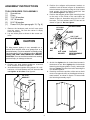
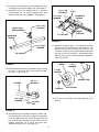
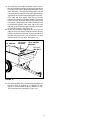
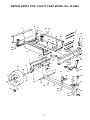
OWNERS
MANUAL
Model No.
45-0240
UTILITY CART
CAUTION:
Read Rules for
Safe Operation
and Instructions
Carefully
Assembly
Operation
Maintenance
Repair Parts
PRINTED IN USA
FORM NO. 46274
LOOSE PARTS IN CARTON
1
4
2
6
3
8
7
5
10
9
11
14
13
12
Carton Contents
1.
2.
3.
4.
5.
6.
7.
8.
9.
10.
11.
12.
13.
14.
Tool Holder Brackets (2)
Tailgate Guides (2)
Corner Caps (2)
Latch Lock Sub-Assembly
Hitch Bracket
Latch Stand Bracket
Tailgate Reinforcement Bracket
Ref.
A
B
C
D
E
F
G
H
I
J
K
L
M
N
O
P
Q
R
S
Qty.
2
2
4
27
6
6
2
41
41
14
14
14
2
2
2
1
1
2
2
Tailgate
Front Panel
Wheel Support
Axle
Draw Bar Tongue
Cart Body (2)
Wheels (2)
Description
Hub Cap
Cotter Pin, 1/8" Dia. x 1-1/2"
Washer, Flat 1.032" ID
Hex Bolt, 1/4" x 1/2"
Hex Bolt, 1/4" x 5/8"
Hex Bolt, 1/4" x 3/4"
Hex Bolt, 1/4" x 1-3/4"
Lock washer, 1/4" ID
Hex Nut, 1/4" Thread
Slotted Truss Hd Bolt, 5/16" x 3/4" Lg.
Lock Washer 5/16" ID
Hex Nut 5/16" Thread
Hex Bolt, 3/8" x 1"
Lock Washer, 3/8" ID
Hex nut, 3/8" Thread
Hitch Pin
Hairpin Cotter
Spacer Tube, 2" Lg.
Protective Edging Strip
A
E
F
I
J
L
P
D
C
B
H
G
K
O
N
M
R
Q
S
FIGURE 1 - HARDWARE PACK
2
5. Position the tailgate reinforcement bracket on
outside of cart as shown in figure 3. Assemble to
holes in bottom of cart body using six 5/16" slotted
head screws, 5/16"lock washers and 5/16" hex
nuts. Do not tighten. See figure 3.
6. Position the tailgate guides (with mounting holes
to the rear) on the inside of the cart bodies as
shown in figure 3. Assemble using six 1/4" x 3/4"
hex bolts, 1/4" lock washers and 1/4" hex nuts as
shown in figure 3. Do not tighten.
ASSEMBLY INSTRUCTIONS
TOOLS REQUIRED FOR ASSEMBLY
(1)
Screwdriver
(1)
Pliers
(2)
7/16" Wrenches
(2)
1/2" Wrenches
(2)
9/16" Wrenches
(1)
Power Drill (See paragraph 19, Pg. 6)
1/4" x 3/4"
HEX BOLT
5/16" X 3/4"
SLOTTED BOLT
1/4"
HEX
NUT
CAUTION
To help prevent tipping of cart, assemble on a
smooth level surface such as a garage floor or a
paved driveway. Pay close attention to stability of the
cart body when it is in an upright position. DO NOT
LEAVE THE CART UNATTENDED IN UPRIGHT
POSITION. The cart could be knocked over causing
personal injury or damage to the cart.
5/16" HEX
NUT
5/16" LOCK
WASHER
TAILGATE
REINFORCEMENT
BRACKET
FIGURE 3
7. At this time tighten the six slotted head screws in
the bottom of cart. Next, tighten the six hex bolts
fastening the tailgate guides. Finally, underneath
the cart, tighten the seven hex bolts fastening the
cart bodies together.
8. Carefully reverse the position of the cart so that it
rests on its opposite end, on the tailgate reinforcement bracket, as shown in figure 4. Proceed with
the following assembly steps.
3. Position cart body halves upright on a smooth
level surface as shown in figure 2.
4. Assemble halves together using seven 1/4" x 1/2"
hex bolts, 1/4" lock washers and 1/4" hex nuts. Do
not tighten at this time. See figure 2.
.
TAILGATE GUIDE
1/4" LOCK
WASHER
1. Remove the hardware pack and all loose parts
from the carton. Be sure the carton is empty
before discarding.
2. Lay out all the parts as shown in the carton contents.
1/4" x 1/2"
HEX BOLT
1/4" HEX
NUT
1/4" LOCK
WASHER
FIGURE 2
FIGURE 4
3
9. Assemble the front panel over the open end of the
cart using ten 1/4"x1/2" hex bolts, 1/4" lock washers and 1/4' hex nuts. Insert bolts down through
the two middle holes and the two outside holes in
the bottom of cart body, and through the top,
bottom and middle holes on each side of the cart
body. Check that the cart halves are butted together and tighten the bolts through the bottom of
the cart first; then tighten the bolts through the
sides of the cart. See figure 5.
LEAVE HOLES OPEN FOR
LATCH STAND BRACKET
11. Assemble latch stand bracket using four 1/4" x
5/8" hex bolts, 1/4" lock washers and 1/4" hex
nuts. See figure 7. TIGHTEN.
LATCH STAND BRACKET
1/4" x 5/8"
HEX BOLT
1/4" x 1/2"
HEX BOLTS
1/4" HEX NUT
1/4" LOCK
WASHER
1/4" HEX NUT
1/4" LOCK
WASHER
FIGURE 7
1/4" HEX NUT
12. Assemble two front top corner caps using four
1/4" x 1/2" hex bolts, 1/4" lock washers and 1/4"
hex nuts. Also assemble two 1/4" x 1/2" hex bolts,
1/4" lock washers and 1/4" hex nuts through top
flanges and tailgate reinforcement bracket at the
two rear corners. See figure 8. TIGHTEN.
FIGURE 5
10. Assemble the wheel support to the cart using
eight 5/16" x 3/4" slotted head screws, 5/16" lock
washers and 5/16" hex nuts as shown in figure 6.
Heads of screws go to the inside of cart. Tighten.
SLOTTED SCREW
5/16" x 3/4"
CORNER CAP
1/4" LOCK
NUT
1/4" LOCK
WASHER
WHEEL
SUPPORT
5/16" HEX
NUT
1/4" x 1/2"
HEX BOLT
5/16" LOCK
WASHER
FIGURE 8
FIGURE 6
4
1/4" LOCK
NUT
13. Lower the cart assembly to rest upside down on its
top flanges, with wheel support up. See figure 11.
14. Assemble latch lock subassembly to drawbar
tongue using two 1/4" x 5/8" long hex bolts, lock
washers and hex nuts. Tighten. See figure 9.
1/4" x 1-3/4"
HEX BOLT
DRAW BAR
TONGUE
1/4" LOCK
WASHER
LATCH LOCK
SUB-ASSEMBLY
AXLE
1/4" x 5/8"
HEX BOLT
WHEEL
SUPPORT
1/4" HEX NUT
DRAW BAR
TONGUE
FIGURE 11
1/4" LOCK
WASHER
17. Assemble a spacer tube, a 1" flat washer, a wheel
with the valve stem facing out, and another 1" flat
washer onto the axle as shown in figure 12. Secure with a cotter pin and spread ends so that hub
cap can fit over the cotter pin . Assemble the hub
cap by pressing it onto the flat washer. Repeat for
other end of axle.
1/4" HEX NUT
WHEEL
FIGURE 9
15. Assemble hitch bracket to drawbar tongue, using
two 3/8" x 1" hex bolts, 3/8" lock washers and 3/8"
hex nuts. See figure 10.
1" FLAT
WASHER
AXLE
1" FLAT
WASHER
SPACER TUBE
TONGUE
3/8" x 1"
HEX BOLT
HUB CAP
COTTER PIN
FIGURE 12
3/8" LOCK
WASHER
18. Turn cart over so that it rests right side up on its
wheels.
3/8" HEX
NUT
FIGURE 10
16. Assemble axle and drawbar tongue to wheel support keeping the open side of tongue facing away
from cart. Make sure the latch lock snaps over the
top of latch stand bracket. Secure axle to wheel
support using two 1/4" x 1-3/4" hex bolts, lock
washers and hex nuts. See figure 11.
5
19. To mount the tool holder brackets to the front of
the cart it will be necessary to drill four holes in the
front panel of the cart. (Recommended hole size is
9/32" diameter.) The tool bracket holders may be
used to locate hole positions by placing the bracket
against the front panel and marking the hole locations onto the front panel. The top tool holder
bracket should be positioned equally from each
side of the cart and even with the top edge of the
front panel. The bottom tool holder bracket should
be positioned equally from each side of the cart
with the top of the bracket approximately six inches
up from the bottom. See figure 13.
20. Press the protective edging strips over the top
edge of both tool holder brackets. Mount the tool
holder brackets on the inside of the front panel of
the cart using four 1/4" x 1/2" hex bolts, 1/4" lock
washers and 1/4" hex nuts. See figure 13.
1/4" HEX NUT
1/4" LOCK
WASHER
TOOL HOLDER
BRACKET
1/4" x 1/2"
HEX BOLT
FIGURE 13
21. Place the tailgate down into the tailgate guides so
that the holes in bottom lip of tailgate fit over
heads of slotted head screws in bottom of cart.
This completes the assembly of your cart.
6
GENERAL SAFETY PRECAUTIONS
MAINTENANCE:
At the beginning of each season, lubricate the latch,
latch pivot bolt, and the axle where the draw bar
tongue pivots, with a light machine oil.
1. Grease or oil wheel bearings occasionally. Use
automotive wheel bearing type grease or 20 weight
oil.
2. Keep tires filled to recommended tire pressure of
12-14 Lbs.
Preventing accidents is the responsibility of every
equipment operator. The following general safety
precautions must be fully understood and followed by
every operator.
1. Do not at any time carry passengers in this cart.
It is designed for carrying materials only and not
intended to carry passengers.
2. Do not tow this utility cart on a public throughfare
at any time. The operator is risking injuries from
passing vehicles. Most local ordinances prohibit
operating a cart and tractor such as this on a
public throughfare.
3. When towing cart do not drive to close to a creek
or ditch and be alert for holes and other hazards.
The above could cause you to loose control of the
cart and tractor.
4. Be careful on any grade (hill) and stay off of steep
grades.
5. Maximum towing speed - 10 M.P. H.
NOTE
One cubic foot of dirt weighs approximately 150 lbs.
DO NOT EXCEED WEIGHT CAPACITY OF 1000 LBS.
Bed:
Tailgate:
Tires:
Axle:
Capacity:
Finish:
Approx. Sh. Wt.:
Carton Size:
OPERATION
To dump material from the cart, remove the tailgate by
lifting it straight up and out from between the guides.
Release the spring latch by pulling the latch handle
forward, away from the cart. The cart bed will tilt
backwards to empty its contents. After unloading, pull
the front of the bed down toward the cart tongue until
the latch snaps in place. Replace the tailgate if desired.
To avoid possible injury, be sure that
no one is near the trailer before releasing the latch.
NOTE
For best handling, do not load cart too
heavily behind center of axle.
7
18 Ga. Steel Construction-32-1/2" W; 49"L;
12"H; Approx. Inside Dim.-30" x 46-1/2"
Removable with reinforced guides
15.00" x 6.0" Pneumatic, Turf Tread
1.0" Dia. Steel
Up to 1000 Lbs.
Powder Coated
116Lbs.
18"H x 21"W x 49"L (10.72 Cu.Ft.)
REPAIR PARTS FOR: UTILITY CART MODEL NO. 45-0240
4
22
3
24
25
2
5
1
20
20
20
27
21
14
6
27
25
28
29
24
24
7
20
25
A
1
24
24 25
25
25
24
A
8
20
14
24
25
15
16
24
28
29
18
25
21
17
18
9
10
30
13
26
11
13
23
19
12
24
33
25
31
32
8
REPAIR PARTS LIST FOR UTILITY CART MODEL NO. 45-0240
REF.
NO.
1
2
3
4
5
6
7
8
9
10
11
12
13
14
15
16
17
18
19
20
21
22
23
24
25
26
27
28
29
30
31
32
33
PART
NO.
23985
46138
23502
62458
23767
23918
23492
23507
23297
62455
23014
23988
23488
23484
44678
46272
43093
43601
43014
43175
43866
43012
1509-69
43177
43178
23353
43814
43086
43083
43001
43003
43015
43343
46274
QTY.
2
2
1
1
2
2
1
1
1
1
1
1
1
2
2
2
2
4
2
27
6
6
2
41
41
1
14
14
14
2
2
2
1
1
DESCRIPTION
Cart Body
Protective Edging Strip
Tailgate
Tailgate Reinforcement Bracket
Guide, Tailgate - One Piece
Tool Holder Bracket
Front Panel
Wheel Support
Latch Stand Bracket
Ass'y, Latch Lock
Hitch Bracket
Draw Bar Tongue
Wheel Axle 1" Dia.
Cap, Front Corner
Sleeve Tube (Spacer)
Wheel, 15.00 x 6.00
Cotter Pin, 1/8" Dia. x 1-1/2"
Washer, Flat 1.032" ID
Hub Cap
Hex Bolt, 1/4" x 1/2"
Hex Bolt, 1/4" x 5/8"
Hex Bolt, 1/4" x 3/4"
Hex Bolt, 1/4" x 1-3/4"
Lock washer, 1/4" ID
Hex Nut, 1/4" Thread
Hitch Pin
Slotted Truss Hd Bolt 5/16" x 3/4" Lg.
Lock Washer 5/16" ID
Hex Nut 5/16" Thread
Hex Bolt, 3/8" x 1"
Lock Washer, 3/8" ID
Hex nut, 3/8" Thread
Hairpin Cotter
Owner's Manual
* Purchase Common Hardware Locally
9
10
11
REPAIR PARTS
303 West Raymond
Sullivan, IL. 61951
217-728-8388