1
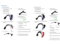
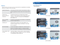
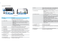
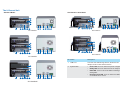
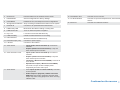
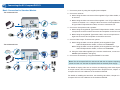
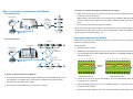
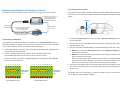
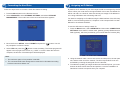
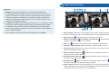
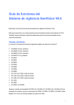
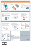
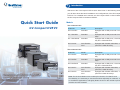
1
Introduction
Welcome to the GV-Compact DVR V3 Quick Start Guide. In the following sections,
you will learn about the basic installations and configurations of the GV-Compact
DVR V3. For a detailed user’s manual, see GV-Compact DVR V3 User’s Manual on
the GV-Compact DVR V3 software CD/DVD.
Quick Start Guide
GV-Compact DVR V3
Models
The 4-Channel Unit
Model No.
Model
Description
GV-LX4C3D1
Standard
Equipped with 2 USB ports and 1 hard drive
bay.
GV- LX4C3D2
Standard
Equipped with 2 USB ports and 2 hard drive
bays.
GV- LX4C3D2W
Standard
Equipped with 2 USB ports, 1 hard drive
bay and 1 DVD-RW drive.
GV-LX4C3V
Anti-Vibration
ACC
Equipped with vibration absorbers, 2 USB
ports and 1 hard drive bay.
Model No.
Model
Description
GV-LX8CD1
Standard
Equipped with 4 USB ports and 1 hard drive
bay.
GV-LX8CD2
Standard
Equipped with 4 USB ports and 2 hard drive
bays.
GV-LX8CD2W
Standard
Equipped with 4 USB ports, 1 hard drive
bay and 1 DVD-RW drive.
GV-LX8CV1
Anti-Vibration
ACC
Equipped with vibration absorbers, 4 USB
ports and 1 hard drive bay.
GV-LX8CV2
Anti-Vibration
ACC
Equipped with vibration absorbers, 4 USB
ports and 2 hard drive bays.
The 8-Channel Unit
Thank you for purchasing GV-Compact
pact DVR. This guide is designed to assist the new user in getting
gettin
tting
g
mpact DVR. For advanced information on how to use the GV-Compact
immediate results from the GV-Compact
DVR, please refer to GV-Compact DVR User's Manual on Software DVD.
© 2012 GeoVision, Inc. All rights reserved.
All GeoVision Products are manufactured in Taiwan.
201
2012/10
English
CDVRV3-QG-C
Note: For the Anti-vibration ACC models (GV-LX4C3V, GV-LX8CV1 and
GV-LX8CV2), it is necessary to use the hard drive especially for notebook, vehicle
or surveillance applications, and tightly fasten the unit on the vehicle to prevent
vibration and shock hazard.
Packing List
The 4-Channel Unit
● Power Adaptor 12V, 5.0A x 1
(Standard Model)
The 8-Channel Unit
● Power Cable x 1
(Anti-Vibration Model)
● Power Adaptor 12V, 5.0A x 1
(Standard Model)
● AC Power Cord x 1
(Standard Model)
● AC Power Cord x 1
(Standard Model)
● D-Type Video Cable x 1
● 1 to 5 D-Type Video Cable x 1
● Shorting Cable x 1
(Anti-Vibration Model)
● Shorting Cable x 1
(Anti-Vibration Model)
● D-Type Audio/TV/Spot Monitor
Cable x 1
● Lock Key x 2 (1 Bay), x 4 (2 Bays)
● Round Screws x 6 (1 Bay),
x 12 (2 Bays)
● 6 to 8 D-Type Video/TV/Spot Monitor
Cable x 1
ower Cable x 2
● Camera Power
● T-Cap Screw x 4 (1 Bay),
x 8 (2 Bays)
Bay) x 4 (2 Bays)
● Lock Key x 2 (1 Bay),
● Remote Control x 1
crews x 6 (1 Bay),
● Round Screws
x 12 (2 Bays)
● GV-Compact DVR Quick Start Guide
x1
era Power Cable
Ca
● 1 to 4 Camera
x1
● Power Cable x 1
(Anti-Vibration Model)
● D-Type Audio Cable x 1
● T-Cap Screw x 4 (1 Bay),
x 8 (2 Bays)
● GV-Compact DVR Software CD/DVD
x1
● Remote Control x 1
● GV-NVR Quick Start Guide x 1
● GV-Compact DVR Quick Start Guide
x1
● GV-NVR Software CD/DVD x 1
● GV-Compact DVR Software CD/DVD
x1
● GV-NVR Quick Start Guide x 1
● GV-NVR Software CD/DVD x 1
2
Overview
The 4-Channel Unit
Options
Standard Model
Optional devices can expand your GV-Compact DVR V3’s capabilities and versatility.
Contact your dealer for more information.
11
External IR Receiver
The external IR receiver, with a 5-meter cable (16.4 feet),
10
allows long-distance remote control of GV-Compact DVR
9
8
V3.
GV-GPS 232
GV-GPS 232 Receiver is a Global Position System
Receiver with PS/2
receiver. It can be applied to vehicle tracking and location
Connector
verification. The device is designed for Anti-Vibration
1
2 3 4 5 6 7
13 14
15 16 17
18
19
13 14
15 16 17
18
19
13 14
15 16 17
18
19
GV-LX4C3D1
ACC models only.
2.5” to 3.5” HDD
The HDD converter allows you to install a 2.5’’ SATA HDD
Converter
into GV-Compact DVR V3.
GV-Relay V2
Working with this module, GV-Compact DVR V3 can
11
10
expand the voltage load up to 10A 250V AC / 10A 125V
9
8
AC / 5A 100V DC.
WiFi USB Adaptor
The WiFi USB Adaptor is designed to connect the GV IP
1
2 3 4 5 6 7
devices to the wireless network. It complies with IEEE
GV-LX4C3D2
802.11 b/g/n (Draft 3.0) standards for wireless networking.
Power Adaptor of DC
The power adaptor is used to power on the Anti-Vibration
12V, 5A
ACC model to test the connection. The device is designed
for Anti-Vibration ACC models only.
12
11
10
9
8
1
2 3 4 5 6 7
GV-LX4C3D2W
Anti-Vibration ACC Model
14 75 Ω
When using the Loop function, turn the switches to OFF
positions. The switch number is corresponding to the
channel number. The default setting is ON.
15 Video In/Out
•
11
9
8
•
1
2
3 5 6 7 10
13 20 14 15 16 17
18 19 21
16 Audio/TV In/Out
GV-LX4C3V
No Name
•
•
Description
1
USB Port
Connects the USB storage device, Wireless LAN
adaptor and/or mobile Internet device.
2
System LED
•
•
•
Power LED: Turns on when the power is supplied.
Ready LED: Turns on when the unit is ready for use.
HDD LED: Turns on when the HDD is reading or
writing data.
•
Disk Full/ Fault LED: Turns on when the HDD is full
or read/write error occurs.
3
IR Receiver
Receives data from the infrared remote control.
4
External IR
Connects to an optional External IR receiver.
5
Reset Button
Restarts the unit, and keeps all current configurations.
6
Default Button
Sets all configurations to factory settings.
7
Storage Removal Button
Stops recording and dataches the HDD from the system.
8
HDD Activity LED
Blinks when the HDD is reading or writing data.
9
HDD Power LED
Turns on when the power is supplied.
10 Key Lock
Locks and unlocks the HDD drive bay.
11 HDD Drive Bay
Installs the SATA hard drive for recording.
12 DVD-RW Drive
Writes the DVD disc for data backup.
13 DC Power Input (12V)
Connects to power supply.
•
•
Inputs (4 Blue Connectors/CH1-4): Connects to
cameras.
Outputs (4 Black Connectors/CH1-4): Loops out
each camera input to monitors.
TV Output (1 Black Connector/QUAD): Connects
to a TV monitor.
Spot Monitor Output (1 Black Connector/MUX):
Connects to a spot monitor to display video
sequentially from each video input.
Audio Inputs (4 White Connectors / CH1-4):
Connects to microphones.
Audio Output for playback (1 Red Connector/
AUD-OUT): Connects to speakers. Note the audio
output only works during playback or when receiving
callback audio.
17 VGA Monitor Port
Connects to a PC monitor.
18 LAN Port
Connects to the network.
19 I/O Terminal Block
Connects to input and output devices, PTZ cameras,
and etc.
20 External IR
Connects to an optional External IR receiver.
21 GPS Port
Connects to a GPS 232 receiver.
The 8-Channel Unit
Standard Model
Anti-Vibration ACC Model
1
11
11
10
10
9
8
9
8
13 14
2 3 4 5 6 7
1
15 16 17 18 19
2 3 4 5 6 7
GV-LX8CD1
13 14
15 16 17 18 19
20
13 14
15 16 17 18 19
20
GV-LX8CV1
11
11
10
10
9
8
9
8
1
1
13 14
2 3 4 5 6 7
2 3 4 5 6 7
15 16 17 18 19
GV-LX8CV2
GV-LX8CD2
No Name
1
USB Port
Connects the USB storage device, Wireless LAN
adaptor and/or mobile Internet device.
2
System LED
10
•
•
•
9
8
•
12
11
1
Description
2 3 4 5 6 7
GV-LX8CD2W
13 14
15 16 17 18 19
Power LED: Turns on when the power is supplied.
Ready LED: Turns on when the unit is ready for use.
HDD LED: Turns on when the HDD is reading or
writing data.
Disk Full/ Fault LED: Turns on when the HDD is full
or read/write error occurs.
3
IR Receiver
Receives data from the infrared remote control.
18 VGA Monitor Port
Connects to a PC monitor.
4
Default Button
Sets all configurations to factory settings.
19 I/O Terminal Block
5
Reset Button
Restarts the unit, and keeps all current configurations.
Connects to input and output devices, PTZ cameras,
and etc.
6
Storage Removal Button Stops recording and dataches the HDD from the system.
20 GPS Port
Connects to a GPS 232 receiver.
7
External IR
Connects to an optional External IR Receiver.
8
HDD Activity LED
Blinks when the HDD is reading or writing data.
9
HDD Power LED
Turns on when the power is supplied.
10 Key Lock
Locks and unlocks the HDD drive bay.
11 HDD Drive Bay
Installs the SATA hard drive for recording.
12 DVD-RW Drive
Writes the DVD disc for data backup.
13 DC Power Input (12V)
Connects to power supply.
14 LAN Port
Connects to the network.
15 Video In/Out
•
•
16 Video In/Out & TV-Out
•
•
•
•
17 Audio In/Out
•
•
Inputs (5 Blue Connectors/CH1-5): Connects to
cameras.
Outputs (5 Black Connectors/CH1-5): Loops out
each camera input to monitors.
Inputs (3 Blue Connectors/CH6-8): Connects to
cameras.
Outputs (3 Black Connectors/CH6-8): Loops out
each camera input to monitors.
TV Output (1 Black Connector/QUAD): Connects to
a TV monitor
Spot Monitor Output (1 Black Connector/MUX):
Connects to a spot monitor to display video
sequentially from each video input.
Audio Inputs (8 Red Connectors/CH1-8): Connects
to microphones.
Audio Output for playback (1 White Connector/
AUD-OUT): Connects to speakers. Note the audio
output only works during playback or when receiving
callback audio..
Continued on the reverse
3
Connecting the GV-Compact DVR V3
Basic Connection for Standard Models
1. Connect to power by using the supplied power adaptor.
The 4-Channel Unit
2. Connect to cameras.
● 4-Ch: Using the blue connectors of the supplied D-Type Video Cable, connect
to cameras.
5
Internet
1
● 8-Ch: Using the blue connectors of the supplied 1 to 5 D-Type Video Cable,
connect to cameras 1 to 5. Using the blue connectors of the supplied 6 to 8
D-Type Video/TV/Spot Monitor Cable, connect to cameras 6 to 8.
3. Connect to microphones and a speaker.
2
3
4
● 4-Ch: Using the supplied D-Type Audio/TV/Spot Monitor Cable, connect
microphones to the four white connectors and a speaker to the red connector.
● 8-Ch: Using the supplied D-Type Audio Cable, connect microphones to the
eight red connectors and a speaker to the white connector.
4. Connect video output. There are two options:
A. 4-Ch: Using the black connector (QUAD) of the supplied D-Type
Audio/TV/Spot Monitor Cable, connect to a TV monitor.
The 8-Channel Unit
8-Ch: Using the black connector (QUAD) of the supplied 6 to 8 D-Type
Video/TV/Spot Monitor Cable, connect to a TV monitor.
B. Using the VGA cable supplied by the monitor manufacturer, connect to a VGA
monitor (as illustrated in the figure).
Internet
4
5
5. Connect to the network by using the standard RJ-45 cable.
1
2
Cameras
1-5
3
2
Cameras
6-8
Note: The GV-Compact DVR V3 cannot work with the microphone requiring
power from the unit. Use the microphone that has external power supply.
For details on looping video out on monitors and displaying each video sequentially
on a spot monitor, see Connecting Optional Video Output Devices, Chapter 3 in the
Compact DVR V3 User’s Manual on the software CD/DVD.
For details on installing the hard drive, see Installing Hard Drive, Chapter 3 in the
Compact DVR V3 User’s Manual on the software CD/DVD.
To power on cameras through the vehicle power supply:
Basic Connection for Anti-Vibration ACC Models
3. 4-Ch: Connect the black wire of the Camera Power Cable to Pin 10 and red wire
to Pin 11 on the terminal block.
8-Ch: Connect the black wires of the Camera Power Cables to Pin 18 or Pin 20,
and the red wires of the Camera Power Cables to Pin 17 or Pin 19 on the terminal
block.
The 4-Channel Unit
4
Power Cable
Camera
Power Cable
2
3
4. Connect the Camera Power Cable to cameras.
When the Anti-Vibration ACC model is connected to the vehicle power supply, the unit
will automatically start after you turn on the vehicle ignition. Power is supplied to the
unit as long as the vehicle ignition is on.
VGA Monitor
Vehicle
1 ACC Wire
Cameras
Testing Anti-Vibration ACC Models
The 8-Channel Unit
Before connecting the ACC model to a vehicle, you can power on the unit at other
places for testing and setup.
Cameras
4
VGA Monitor
Power Cable
3
1. Connect the Shorting Cable to Pins 14 and 16 (4-Ch) or Pins 22 and 24 (8-Ch) on
the terminal block.
Camera
Power Cable
3
Vehicle
● Supplied Shorting Cable
● Additional power adaptor (DC 12V, 5A), which can be purchased from GeoVision.
Camera
Power Cable
2
Items required:
1 ACC Wire
2 4 6 8 10 12 14 16
2 4 6 8 10 12 14 16 18 20 22 24
Shorting
Cable
4
Shorting
Cable
Cameras
To power on Anti-Vibration ACC Models:
1 3 5 7 9 11 13 15
Terminal Block of 4-Ch
1 3 5 7 9 11 13 15 17 19 21 23
Terminal Block of 8-Ch
1. Connect the ACC wire from the vehicle to Pin 16 (4-Ch) or Pin 24 (8-Ch) on the
terminal block. For details see Connecting Anti-Vibration ACC Models to the
Vehicle later in the Quick Start Guide.
2. Power on the unit by using a power adaptor. The unit automatically starts after
powering up for 5 seconds.
2. Connect the Power Cable to the unit and to the vehicle.
3. Set up the settings of the unit, such as storage, images, recording and etc through
its OSD or Web interface.
4. Remove the power adaptor. The unit turns off immediately after powering off.
Connecting the Power Wire
Connecting Anti-Vibration ACC Models to a Vehicle
You need to connect the ACC model to ACC wire and power wire on the vehicle.
Connect to Pin 16 (4-Ch) or
Pin 24 (8-Ch) of the
Terminal Block on the
GV-Compact DVR V3
Using the fuse specification diagram, locate the power cables from the fuse box. You
may need to use a voltmeter to determine positive-voltage and negative-voltage
cables.
Fuse Box
GV-Compact DVR V3
The Supplied
Power Cable
ACC wire from
the Vehicle
Connect the white wire to the
Vehicle’s Power Cable
(10 ~ 28 VDC, 5A)
Connect the black wire to the
Vehicle’s Ground Cable
+/Vehicle
Connecting the ACC Wire
1. Connect the white power wire of the unit to the positive-voltage power cable
from the fuse box.
The following instructions are based on installation on a Toyota Zace Surf. Since
each vehicle differs in design, refer to the owner’s manual of your vehicle for details
or have the installation done by a properly trained technician.
2. Remove the car door scuff plate and wire the power cable along the driver’s door
toward the back seat.
1. Locate and open the fuse box, which is usually located below the dashboard and
to the left of the steering wheel.
2. Look for “cigarette lighter” fuse location, which is indicated in the fuse
specification diagram on the fuse box or in the owner’s manual.
3. Connect the ACC wire from the cigarette lighter fuse to Pin 16 (4-Ch) or Pin 24
(8-Ch) on the terminal block.
2 4 6 8 10 12 14 16 18 20 22 24
2 4 6 8 10 12 14 16
ACC wire of
the Vehicle
1 3 5 7 9 11 13 15 17 19 21 23
Terminal Block of 4-Ch
Terminal Block of 8-Ch
● Method 1: Connect the black ground wire to the negative-voltage power
cable from the fuse box.
● Method 2: Connect the black ground wire to the vehicle’s chassis so that the
wire contacts the bare metal.
When the black ground wire is connected correctly, the unit will automatically
shut down 30 seconds after the car’s power is off. If the unit does not shut
down, try to connect the black ground wire using the other method.
4. Turn on the car ignition and the unit should start automatically within 5 seconds.
Turn off the car ignition and the unit should shut down 30 seconds after the car
ignition is off.
ACC wire of
the Vehicle
1 3 5 7 9 11 13 15
3. Use one of the two methods below to connect the black ground wire of the unit.
For details, see 3.3.2 Connecting to a Vehicle, Chapter 3 in GV-Compact DVR V3
User’s Manual on the software CD/DVD.
4
5
Formatting the Hard Drive
Follow the steps below to format the hard drive before recording.
1. Press the Menu button on the Remote Control.
2. Select ADVANCED, select STORAGE SETTINGS, and select STORAGE
MANAGEMENT. The model name of the connected hard drive appears.
Assigning an IP Address
By default, the IP address of your GV-Compact DVR V2 is assigned by the DHCP
server unless your router does not support DHCP. In this case, the default IP address
will be 192.168.0.10. However, there are two ways to assign an IP address to the
unit: Using OSD Menu and Connecting with a PC
For detail on assigning an IP address using the Web interface of the GV-Compact
DVR V3, see Connecting with a PC, Chapter 5 in GV-Compact DVR V3 User’s
Manual on the software CD/DVD.
To use the OSD menu to assign a static IP:
1. Press the Menu button, select NETWORK and then select CONNECTION
SETTINGS. Set a static IP, subnet mask, gateway, primary DNS and secondary
DNS (optional), which are provided by your Internet Service Provider (ISP).
3. Move the focus to DETAIL, select FORMAT and press the
be prompted to confirm the action.
button. You will
4. Select YES and press the
button to start formatting. The format progress will
appear in the top right of the screen, e.g. “PART 1: 94/100”. When the format is
complete, the amount of free disk space will be displayed.
Note:
1. The maximum space of one partition is 200 GB.
2. The connected USB mass storage device must also be formatted according
to above instructions before use.
2. Using the network cable, connect one end to the LAN port on the rear panel of the
unit, and the other end to the network. The GV-Compact DVR V3 is now
accessible by entering the assigned IP on the browser.
3. To enable the updating of images in Microsoft Internet Explorer, you must set your
browser to allow ActiveX Controls and perform a one-time installation of
GeoVision’s ActiveX component onto your computer.
6
Main Screen Overview
1
Important:
2
3 4
5
11
7
1. PPPoE should only be enabled, if you know which IP address the
GV-Compact DVR V3 will get from the ISP. Otherwise, you must use the
Dynamic DNS service to obtain a domain name linked to the GV-Compact
DVR V3’s changing IP address first. For details on Dynamic DNS Server
settings, see Advanced TCP/IP, Chapter 6 in GV-Compact DVR V3 User’s
Manual on the software CD/DVD
2. If PPPoE is enabled and you cannot access the unit, you may have to reset it
to the factory default settings and then perform the network settings again.
For details on how to restore to factory default settings, see Restoring to
Factory Default Settings, Chapter 8 in GV-Compact DVR V3 User’s Manual
on the software CD/DVD.
3. The default login name and password for Administrator are admin.
10 9 6
8
1. Date and time: Indicates the current date and time when viewing live video.
2. A / B / C: Indicates the type of device defined for the GV-Compact DVR V3.
3. Monitoring icon
: Appears when the monitoring is activated.
4. Manual recording icon or Schedule recording icon
recording is started manually or by schedule.
5. Input icon
: Appears when the
: Appears when the input device is installed and activated.
6. Channel number/Camera name: Displays the camera number or name.
7. Hard disk status: Indicates the amount of free space on the hard disk. When the
disk is full, the status will turn to red.
8. Motion detection mode icon
: Appears when the camera is set to the
recording mode of motion detection.
9. Round-the-clock mode icon
: Appears when the camera is set to the
recording mode of round-the-clock.
10. Recording icon
: Appears when the monitoring is started. A red icon
indicates the image of the camera is being recorded.
11. Vehicle speed: Indicates the average speed of the vehicle when the GPS
function is enabled. This function is only available for the Anti-Vibration ACC
models (GV-LX4C3V, GV-LX8CV1 and GV-LX8CV2).
7
Basic
Operations
Upgrading
System Firmware
You can perform the following basic operations using the remote control.
8
Upgrading System Firmware
GeoVision will periodically release the updated firmware on the website. To load the
new firmware into the GV-Compact DVR V3, read the important notes below and then
follow the instructions.
Important:
1. While the firmware is being updated, the power supply must not be
interrupted.
2. Do not turn the power off for 10 minutes after the firmware is updated.
3. If you use the IP Device Utility for firmware upgrade, the computer used to
upgrade firmware must be under the same network of the GV-Compact DVR
V3.
1. In the Live View window, click the Show System Menu button and select Remote
Config. This dialog box appears.
Operations
Steps
Date/Time Adjustment
Press the Menu button, select ADVANCED and then
select DATE AND TIME.
Recording Operation
Press the Rec button to start recording and press the
Stop button to stop recording.
Search and Playback
Press the Search button to see the search and
playback options.
PTZ Control
Press the Channel button to display the PTZ channel
and use the directional buttons to control the PTZ
movement.
2. Click the Browse button to locate the firmware file (.img) saved at your local
computer.
Channel Number and
Camera Name
Press the Menu button, select Channel Settings and
then Channel Name to change the camera name.
Press the Menu button, select Advanced and then
Display Settings to display the channel number or
camera title.
WARNING: The interruption of power supply during updating causes not only
update failures but also damages to the GV-Compact DVR V3. In this case,
please contact your sales representative and send your device back to
GeoVision for repair.
Video Backup
Press the Menu button, select Advanced and then
Backup to specify the time and channel for backing
up video files.
3. Click the Upgrade button to start the upgrade.
9F, No. 246, Sec. 1, Neihu Rd., Neihu District, Taipei, Taiwan
Tel: +886-2-8797-8376
[email protected]
Fax: +886-2-8797-8335
http://www.geovision.com.tw