1
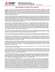
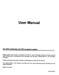
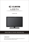
Analog RGB input board(Option)
Specification
M o d el N a m e
VS-L55HM70U
Model number
D i s p la y Ori en tati o n
Landscape/Portrait
Signal input terminal(Analog RGB)
D i s p la y D e v i c e
TFT LCD(SPVA Mode)
B a c k L i g h t Tehcnology
LED(Direct)
D i s p la y R eso lu ti o n
Full HD(1920 x 1080 Pixels)
Vi e w a b le I m age S i z e
55"(H:1209.6mm/V:680.4mm)
RGB input scanning frequency
700cd/m 2(Typ.)@Bright Mode
500cd/m 2(Typ.)@Normal Mode
B r ig h t n e s s
VC-B70G2
5BNC x1, HD D-sub 15 pins x1
Signal resolutions
VGA(640 x 480) - WUXGA(1920 x 1200)
Horizontal
31.5kHz - 92kHz
Vertical
49Hz - 85Hz
Pixel clock rate
25MHz - 162MHz
Functions
Image scaling(shrink and zoom)
Frame rate conversion
350cd/m 2(Typ.)@Eco Mode
C on t r a s t R ati o
3500:1(Typ.)
Vi e w in g A ngle( H/V )
178Degree
D i s p la y C o lo rs
16.7Million
Model number
M u l l i o n ( To tal)
5.7mm(Typ.)/6.7mm(Typ.) *
Signal input terminal(Digital RGB)
B a c k Li g h t O perati n g Li f e
50000hrs(Average)
O p t io n a l I n pu t Bo ard S lo t
x3(One VC-B70DC card is pre-installed)
Digital RGB input board(Option)
RGB input scanning frequency
RS-232C: Dsub9
C on t r ol Si g n al In pu t
Display Wall
VC-B70D2
DVI-D x2
Signal resolutions
VGA(640 x 480) - WUXGA(1920 x 1200)
Horizontal
31.5kHz - 92kHz
Vertical
49Hz - 85Hz
LAN: RJ45(10BASE-T/100BASE-TX)
Pixel clock rate
25MHz - 162MHz
Dsub 9 x 2(IN/OUT)
Mitsubishi Original Control Link
Sigal format
TMDS
Functions
Image scaling(shrink and zoom)
Frame rate conversion
Wired Remote: F3.5 Jack
IR Receiver(Option)
I n p u t Si g n al
Refer to the bottom input board(Option) specifications
O v e r la y F un c ti o n
Max. 6 Windows per each screen (with VC-B70V2)
Max. 3 Windows per each screen (with other boards)
C on t r ol S/W ( O pti o n )
Mitsubishi D-Wall Software Suite
210W(Typ.)@Bright Mode
170W(Typ.)@Normal Mode
P o w er C o nsu m pti o n
150W(Typ.)@Eco Mode
Vo lt a g e R an ge
AC100-240V±10%,50/60Hz±1Hz
D i men s i on s
1215.3mm(W) x 686.1mm(H) x 173mm(D)
47.8inch(W) x 27inch(H) x 6.8inch(D)
O p e r a t in g C o n di ti o n
5-35C.Degree(41-95F.Degree)@Normal/Eco Mode
5-30C.Degree(41-86F.Degree)@Bright Mode
Wei g h t
40Kg/88lbs
VC-B70V2
Signal input terminal(Analog Video)
3BNC x2
Analog video input signals
NTSC, NTSC4.43, PAL, PAL-M, PAL-N
PAL-60, SECAM
Functions
Image scaling(shrink and zoom)
Frame rate conversion
Daisy chain board(Option)
VC-B70DC
Model number
Analog RGB: HD D-sub15pins x1
Digital RGB: DVI-D x1
3.8
680.4 (Active Area)
686.1
1209.6 (Active Area)
Analog video: 3BNC x1
Signal output terminal
RGB input scanning frequency
Digital RGB: DVI-D x 1(for daisy chain use only)
Signal resolutions
VGA(640 x 480) - WUXGA(1920 x 1200)
Horizontal
31.5kHz - 92kHz
Vertical
49Hz - 85Hz
Analog video input signals
NTSC, NTSC4.43, PAL, PAL-M, PAL-N
PAL-60, SECAM
Pixel clock rate
25MHz - 162MHz
1.9
171
3.8
Model number
Signal input terminal
*When using with Wall Mount Frame BR-HM70KK(option).
99
173
Video input board(Option)
Image scaling(shrink and zoom)
1.9
1215.3
Functions
Frame rate conversion
Daisy chain(Up to 16 cubes)
700
300
150
8-M6 Depth 10
3G-SDI input board(Option)
Model number
V C- B 70SD 1
Signal input terminal
H D - SD I : B N C x1
3G-SDI (SMPTE424M): 1080p@50/59.94/60Hz
300
150
HD-SDI (SMPTE292M): 1080i@50/59.94/60Hz,
720p@50/59.94/60Hz
Input signals
SD-SDI (SMPTE259-C): [email protected],576@50Hz
150
300
150
Signal output terminal
H D - SD I : B N C x1( f o r th ro ugh ou t p u t )
Gen Lock input termninal
B N C x1
Functions
I mag e s cali n g ( s h ri n k an d z oom )
F rame rate co n ve rs i o n th r ou gh ou t p u t
*At least one input board per single display is needed for operation.
*The specifications are subject to change without notices.
Long time usage of this product is subject to environmental conditions and the
content of the display.
For more details, please refer to Mitsubishi Electric's Operational Manual (for
long time usage).
HEAD OFFICE: TOKYO BLDG., 2-7-3, MARUNOUCHI, CHIYODA-KU, TOKYO 100-8310, JAPAN
http://global.mitsubishielectric.com/bu/displaywall/
L-188-1-C8838-B KYO 1209 Printed in Japan(MDOC)
Revised publication effective Sep. 2012
Superseding publication of L-188-1-C8838-A Aug. 2011
Specifications are subject to change without notice.
VS-L55HM70U
55" LCD Display Wall
Mitsubishi Electric
L C D D i s p l a y Wa l l S y s t e m S o l u t i o n s
We have extensive expertise in this field, including the installation of
The Mitsubishi Electric LCD Display Wall System is the ideal solution for small-and medium-sized control rooms
slot-in board processing, this display wall system is perfect
for the following applications:
>Power distribution/
Water treatment management
>Broadcasting
It features an advanced technology system that provides intelligence, durability, redundancy and space savings.
Bezel compensation
5.7mm mullion (total)
Front access for easy service
Super narrow 5.7mm mullion (total) minimizes the image content loss,
which is critical for command and control room usage.
When used in combination with Mitsubishi Electric’s original optional
wall mount kit, LCD panels can be accessed from the front-side of the
system. This design makes it possible for panels to be serviced from the
front as well as the rear.
Key Feature
Key Feature
Images can be displayed in two modes, Real Picture Window (RPW) or
Natural Picture Window (NPW).
RPW displays images using the entire input signal (no image loss), making it
suitable for displaying surveillance images and similar applications.
NPW realizes a smoothly connected screen image appearance when using
multiple screens; perfect for moving pictures.
Image portions
corresponding to
the bezel width
are not hidden
(no image loss).
5.7mm
Wall
Image portions
corresponding to the bezel
width are hidden,
realizing a naturally
connected image.
User-friendly graphical user interface
(Option)
“D-Wall”, a software suite developed by Mitsubishi Electric, is
available for LCD Wall System. The software was originally
created for use with the display wall cube and processor, and
has been continuously modified and upgraded.
In addition to basic functions such as wall configuration
support, display layout control, and brightness and color
control, the following functions for control room use have
been incorporated into the latest version.
Key Feature
Digital gradation circuit
RPW
Mitsubishi Electric's innovative digital gradation circuit provides uniform
brightness distribution across the screen, resulting in the reproduction of
sharp, vivid images form edge to edge on multi-screen configurations.
This virtually eliminates the problem of decreased brightness at the edges
of each screen.
With “Digital Gradation Circuit”
Without “Digital Gradation Circuit”
>Security operations
Combining a space-saving design and easy video/data integration using
that require high picture quality from displays.
High picture quality over the entire wall
>Traffic management
over 50,000 display wall cubes for mission-critical applications.
Color space control
Our LCD displays are equipped with an innovative digital color
space control circuit developed in-house. The circuit works to balance
and blend colors, compensating for the color and brightness discrepancies among LCD displays.
NPW
3 operational modes
Internal processing
Key Feature
Built-in processor
Each display of LCD Display Wall System is equipped with an internal
data-processing function that allows to show up to six windows (with
VC-B70V2) or three windows (with other boards) per a single panel,
and allows to show up to three windows placed any size and position
across the entire wall when using the daisy chain function of the daisy
chain board.
Install Mitsubishi Electric's D-Wall software suite and the entire imaging
system can be controlled intuitively from a user-friendly graphical user
interface.
Without overlay function
Black strips are displayed on
both sides when the image source is
set to the 4:3 aspect ratio.
Only one screen can be displayed at
a time.
With overlay function
Freely choose the size and position of the image windows.
Key Feature
Three backlight power modes (Bright, Normal and Eco) can be selected
according to the operating environment.
Normal mode
Redundancy
Bright mode
Eco mode
Key Feature
Smart Switch
The LCD Display Wall System is also equipped with a “Smart Switch".
This signal source control function provides the redundancy necessary
for mission-critical applications that require continuous operation. If
the signal is unexpectedly lost, the signal source is automatically
switched to an alternative device (either "port-to-port" or "board-toboard") within seconds of detecting the 'no signal' status. As a result,
user downtime is minimized in the event of a signal source failure.
Remote multi-mouse cursor application control
When being operated under a client-server configuration,
multiple users (clients) can simultaneously navigate applications using their dedicated mouse. Individual cursors, colorcoded for each mouse, are shown on the display wall, and all
clients can control applications on the server. This function
simultaneously enables more efficient control room operation
and room layout flexibility.
Alert message utility
Without “Color Space Controll”
With “Color Space Controll”
Dynamic brightness balancing
With a built-in brightness sensor, Dynamic brightness balancing circuit can
keep the brightness uniformity of display wall over the period of operation
time by periodically communicating the measured brightness data.
Example 2x2 display wall
100%
Brightness
50%
As the black line indicates,
the brightness level of
the 2x2 display wall is maintained at
the same brightness
Time
This information function displays alerts and notices on the
wall, supporting teamwork in the control room.
System monitoring
This management function constantly monitors key operating
parameters of the LCD Wall System such as the status of
cooling fans and temperature inside the displays. The information for each display us displayed via the GUI.
Multilingual interface
The D-wall software suite is available in multiple languages.