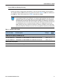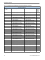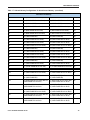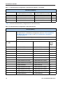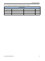
1
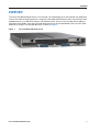
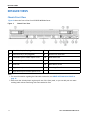
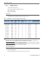
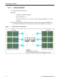
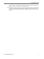
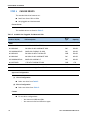
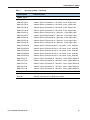
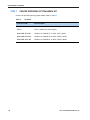
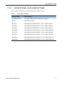
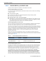
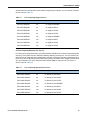
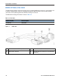
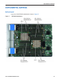
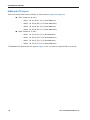
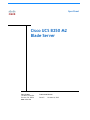
Spec Sheet
Cisco UCS B250 M2
Blade Server
CISCO SYSTEMS
170 WEST TASMAN DR.
SAN JOSE, CA, 95134
WWW.CISCO.COM
PUBLICATION HISTORY
REV A.5
OCTOBER 16, 2012
CONTENTS
OVERVIEW . . . . . . . . . . . . . . . . . . . . . . . . . . . . . . . . . . . . . . . . . . . . . . . 3
DETAILED VIEWS . . . . . . . . . . . . . . . . . . . . . . . . . . . . . . . . . . . . . . . . . . . 4
Chassis Front View . . . . . . . . . . . . . . . . . . . . . . . . . . . . . . . . . . . . . . . . . . . . . . . . . . .4
BASE SERVER STANDARD CAPABILITIES and FEATURES . . . . . . . . . . . . . . . . . 5
CONFIGURING the SERVER . . . . . . . . . . . . . . . . . . . . . . . . . . . . . . . . . . . . 6
STEP
STEP
STEP
STEP
STEP
STEP
STEP
STEP
STEP
ORDER
1 VERIFY BASE SKU . . . . . . . . . . . . . . . . . . . . . . . . . . . . . . . . . . . . . . . . . . . . . . 7
2 CHOOSE CPU(S) . . . . . . . . . . . . . . . . . . . . . . . . . . . . . . . . . . . . . . . . . . . . . . 8
3 CHOOSE MEMORY . . . . . . . . . . . . . . . . . . . . . . . . . . . . . . . . . . . . . . . . . . . . 10
4 CHOOSE DRIVES . . . . . . . . . . . . . . . . . . . . . . . . . . . . . . . . . . . . . . . . . . . . . 16
5 CHOOSE MEZZANINE OPTION CARD(S) . . . . . . . . . . . . . . . . . . . . . . . . . . . . . . . 17
6 CHOOSE OPERATING SYSTEM . . . . . . . . . . . . . . . . . . . . . . . . . . . . . . . . . . . . . 18
7 CHOOSE OPERATING SYSTEM MEDIA KIT . . . . . . . . . . . . . . . . . . . . . . . . . . . . . . 20
8 CHOOSE OPTIONAL VALUE-ADDED SOFTWARE . . . . . . . . . . . . . . . . . . . . . . . . . . 21
9 CHOOSE SERVICE and SUPPORT LEVEL . . . . . . . . . . . . . . . . . . . . . . . . . . . . . . 22
OPTIONAL KVM CABLE . . . . . . . . . . . . . . . . . . . . . . . . . . . . . . . . . . . . . . . . . . . 26
SUPPLEMENTAL MATERIAL . . . . . . . . . . . . . . . . . . . . . . . . . . . . . . . . . . . 27
Motherboard . . . . . . . . . . . . . . . . . . . . . . . . . . . . . . . . . . . . . . . . . . . . . . . .
DIMM and CPU Layout . . . . . . . . . . . . . . . . . . . . . . . . . . . . . . . . . . . . . . . . . .
Memory Population Recommendations . . . . . . . . . . . . . . . . . . . . . . . . . . .
Allowed Memory Configurations . . . . . . . . . . . . . . . . . . . . . . . . . . . . . . .
....
....
....
....
. . 27
. . 28
. . 30
. . 31
TECHNICAL SPECIFICATIONS . . . . . . . . . . . . . . . . . . . . . . . . . . . . . . . . . . 36
Dimensions and Weight . . . . . . . . . . . . . . . . . . . . . . . . . . . . . . . . . . . . . . . . . . . . . . . 36
Power Specifications . . . . . . . . . . . . . . . . . . . . . . . . . . . . . . . . . . . . . . . . . . . . . . . . 36
Cisco UCS B250 M2 Blade Server
2
OVERVIEW
OVERVIEW
The Cisco® UCS B250 M2 Blade Server is a two-socket, full-width blade server that extends the capabilities
of the Cisco Unified Computing System™, using Intel's Xeon 5600 and 5500 Series multi-core processors with
48 DIMM slots for up to 384 GB of memory, two mezzanine slots, and up to two hard disk drives (HDDs) or
solid-state drives (SSDs). Up to four full-width blade servers can be accommodated in the Cisco UCS 5108
Blade Server Chassis. The UCS B250 M2 server is shown in Figure 1.
Figure 1
Cisco UCS B250 M2 Blade Server
Cisco UCS B250 M2 Blade Server
3
DETAILED VIEWS
DETAILED VIEWS
Chassis Front View
Figure 2 shows the front of the Cisco UCS B250 M2 Blade Server.
Figure 2
Chassis Front View
1
Hard drive bay 1 (hot-pluggable)
8
Power button and LED
2
Hard drive bay 2 (hot-pluggable)
9
Network link status LED
3
Left blade ejector handle captive screw
10
Blade health LED
4
Left blade ejector handle
11
Console connector1
5
Asset tab2
12
Reset button access
6
Right blade ejector handle
13
Beaconing LED and button
7
Right blade ejector handle captive screw
Notes . . .
1. For more information regarding the KVM cable connection, see ORDER OPTIONAL KVM CABLE on
page 26
2. Each server has a blank plastic tag that pulls out of the front panel, so you can add your own asset
tracking label without interfering with the intended air flow
4
Cisco UCS B250 M2 Blade Server
BASE SERVER STANDARD CAPABILITIES and FEATURES
BASE SERVER STANDARD CAPABILITIES and FEATURES
Table 1 lists the capabilities and features of the base server. Details about how to configure the server for
a particular feature or capability (for example, number of processors, disk drives, or amount of memory)
are provided in CONFIGURING the SERVER on page 6.
Table 1 Capabilities and Features
Capability/Feature
Description
Chassis
The B250 M2 Blade Server mounts in a Cisco UCS 5100-series chassis
CPU
Up to two Intel® Xeon® 5500 or 5600 series processors
Chipset
Intel® 5520 (Tylersburg) chipset
Memory
48 slots for registered DIMMs, up to 384 GB of memory.
Expansion slots
Two mezzanine slots are provided
Storage controller
Onboard LSI 1064E RAID controller
Factory-configured RAID support options:
■
RAID 0 and 1
Internal storage devices
Up to two optional front-accessible, hot-pluggable small form factor (SFF)
SATA solid-state disk drives (SSDs) or SAS hard disk drives (HDDs).
Video
The server CIMC chip includes a Matrox G200 core. The first 8 MB of memory
are allocated to the video core.
Interfaces
■
Front panel
• One console connector (see ORDER OPTIONAL KVM CABLE on page
26)
Power subsystem
Integrated in the Cisco UCS 5100 series chassis
Fans
Integrated in the Cisco UCS 5100 series chassis
Integrated management
processor
The built-in Cisco Integrated Management Controller (CIMC) GUI or CLI
interface enables you to monitor the server inventory, health, and system
event logs.
Cisco UCS B250 M2 Blade Server
5
CONFIGURING the SERVER
CONFIGURING the SERVER
Follow these steps to configure the Cisco UCS B250 M2 Server:
6
■
STEP 1 VERIFY BASE SKU, page 7
■
STEP 2 CHOOSE CPU(S), page 8
■
STEP 3 CHOOSE MEMORY, page 10
■
STEP 4 CHOOSE DRIVES, page 16
■
STEP 5 CHOOSE MEZZANINE OPTION CARD(S), page 17
■
STEP 6 CHOOSE OPERATING SYSTEM, page 18
■
STEP 7 CHOOSE OPERATING SYSTEM MEDIA KIT, page 20
■
STEP 8 CHOOSE OPTIONAL VALUE-ADDED SOFTWARE, page 21
■
STEP 9 CHOOSE SERVICE and SUPPORT LEVEL, page 22
Cisco UCS B250 M2 Blade Server
CONFIGURING the SERVER
STEP 1
VERIFY BASE SKU
Verify the product ID (PID) of the base server as shown in Table 2.
Table 2 PID of the Base B250 M2 Server
Product ID (PID)
N20-B6625-2
Description
UCS B250 M2 Blade Server w/o CPU, memory, HDD, mezzanine
The B250-BASE-M2 base server:
■
Does not include CPUs, memory DIMMs, solid-state Drives (SSDs), hard disk drives (HDDs), or
any mezzanine cards.
NOTE: Use the steps on the following pages to configure the server with
the components that you want to include.
Cisco UCS B250 M2 Blade Server
7
CONFIGURING the SERVER
STEP 2
CHOOSE CPU(S)
The standard CPU features are:
■
Intel Xeon 5600-series (Westmere-EP) CPUs
■
Intel 5520 chipset
■
Cache size of 12 MB
Choose CPUs
The available Intel Xeon 5600-series CPUs are listed in Table 3.
Table 3 Available CPUs: Intel Xeon Westmere-EP x56xx Family
Product ID (PID)
Intel
Number
Clock
Freq
(GHz)
Power
(W)
Cache
Size (MB)
Cores
QPI
Highest DDR3 DIMM
Clock Support (MHz)1
UCS-CPU-X5687
X5687
3.60
130
12
4
6.4 GT/s
1333
A01-X0115
X5690
3.46
130
12
6
6.4 GT/s
1333
A01-X0100
X5680
3.33
130
12
6
6.4 GT/s
1333
A01-X0117
X5675
3.06
95
12
6
6.4 GT/s
1333
A01-X0102
X5670
2.93
95
12
6
6.4 GT/s
1333
A01-X0105
X5650
2.66
95
12
6
6.4 GT/s
1333
A01-X0109
E5640
2.66
80
12
4
5.86 GT/s
1066
A01-X0120
E5649
2.53
80
12
6
5.86 GT/s
1333
A01-X0111
E5620
2.40
80
12
4
5.86 GT/s
1066
A01-X0106
L5640
2.26
60
12
6
5.86 GT/s
1333
Notes . . .
1. If you select higher or lower speed DIMMs than what is shown in the table for a given CPU, the DIMMs will be
clocked at the lowest common denominator of CPU clock and DIMM clock. For example:
Selecting lower-speed DIMMs: If you use an X5690 CPU (which can support up to 1333-MHz DIMMs) with 1066-MHz
DIMMs, the DIMMs will be clocked at the lower speed of 1066 MHz.
Selecting higher-speed DIMMs: If you use 1333-MHz DIMMs with an E5620 CPU (which can support up to 1066-MHz
DIMMs), the DIMMS will be clocked at the lower speed of 1066 MHz.
Approved Configurations
(1) One-CPU Configuration
■
8
Choose one identical CPU from any one of the rows of Table 3.
Cisco UCS B250 M2 Blade Server
CONFIGURING the SERVER
(2) Two-CPU Configuration
■
Choose two identical CPUs from any one of the rows of Table 3 on page 8.
Caveats
■
For optimal performance, select DIMMs with the highest clock speed for a given processor
(see Table 4 on page 11). If you select DIMMs whose speeds are lower or higher than that
shown in the tables, suboptimal performance will result.
Cisco UCS B250 M2 Blade Server
9
CONFIGURING the SERVER
STEP 3
CHOOSE MEMORY
The standard memory features are:
■
■
Figure 3
10
DIMMs
—
Maximum clock speed: 1333 MHz
—
Ranks per DIMM: 1 or 2
—
Operational voltage: 1.5 or 1.35 V (the system operates the DIMMs at 1.5 V only)
—
Registered
Each CPU controls three DDR3 channels. Each of the channels controls eight DIMMs. The
total number of DIMMs that can be installed per CPU is 24 (12 DIMM kits). See Figure 3.
B250 M2 Memory Organization
Cisco UCS B250 M2 Blade Server
CONFIGURING the SERVER
Choose DIMMs and Memory Mirroring
Choose the memory configuration and whether or not you want the memory mirroring option.
The available memory DIMMs and mirroring option are listed in Table 4. DIMMs are available as
two-DIMM kits. Each of the product IDs in Table 4 specifies two DIMMs.
NOTE: When memory mirroring is enabled, the memory subsystem simultaneously
writes identical data to two channels. If a memory read operation from one of the
channels returns incorrect data due to an uncorrectable memory error, the system
automatically retrieves the data from the other channel. A transient or soft error in
one channel does not affect the mirrored data, and operation continues unless there
is a simultaneous error in exactly the same location on a DIMM and its mirrored
DIMM. Memory mirroring reduces the amount of memory available to the operating
system by 50 percent because only one of the two populated channels provides data.
Table 4 Available DDR3 DIMMs
Product ID (PID)
PID Description
Voltage
Ranks/
DIMM
DIMM Pair Kit Options (2 DIMMs per kit)
UCS-MR-2X041RX-B
2X4GB DDR3-1333-MHz RDIMM/PC3-10600/1R/x4/Low-Volt
1.35/1.5 V
1
UCS-MR-2X082RX-B
2X8GB DDR3-1333-MHz RDIMM/PC3-10600/2R/x4/Low-Volt
1.35/1.5 V
2
Memory Mirroring Option
N01-MMIRROR
Memory mirroring option
Cisco UCS B250 M2 Blade Server
11
CONFIGURING the SERVER
Approved Configurations
(1) 1-CPU Configuration Without Memory Mirroring
■
24 DIMMs capacity total
■
Select 1, 2, 4, 8, or 12 DIMM kits (2, 4, 8, 16, or 24 DIMMs) for CPU1. The DIMMs will be
placed by the factory as shown in the following table:
Number of
DIMMs
(CPU1)
DIMM Placement in Numbered/Colored DIMM Slots
(see Figure 6 on page 29)
2
(A0, A1) - blue slots
4
(A0, A1) – (A4, A5) - blue slots
8
(A0, A1) – (A4, A5) - blue slots; (A2, A3) – (A6, A7) - black slots
16
(A0, A1) – (A4, A5) - blue slots; (A2, A3) – (A6, A7) - black slots
(B0, B1) – (B4, B5) - blue slots; (B2, B3) – (B6, B7) - black slots
24
(A0, A1) – (A4, A5) - blue slots; (A2, A3) – (A6, A7) - black slots
(B0, B1) – (B4, B5) - blue slots; (B2, B3) – (B6, B7) - black slots
(C0, C1) – (C4, C5) - blue slots; (C2, C3) – (C6, C7) - black slots
(2) 2-CPU Configuration Without Memory Mirroring
■
48 DIMMs capacity total
■
Select 1, 2, 4, 8, or 12 DIMM kits (2, 4, 8, 16, or 24 DIMMs) per CPU. The DIMMs will be placed
by the factory as shown in the following table:
Number of
DIMMs
DIMM Placement in Numbered/Colored DIMM Slots
(see Figure 6 on page 29)
CPU1
12
2
(A0, A1) - blue slots
4
(A0, A1) – (A4, A5) - blue slots
8
(A0, A1) – (A4, A5) - blue slots; (A2, A3) – (A6, A7) - black slots
16
(A0, A1) – (A4, A5) - blue slots; (A2, A3) – (A6, A7) - black slots
(B0, B1) – (B4, B5) - blue slots; (B2, B3) – (B6, B7) - black slots
24
(A0, A1) – (A4, A5) - blue slots; (A2, A3) – (A6, A7) - black slots
(B0, B1) – (B4, B5) - blue slots; (B2, B3) – (B6, B7) - black slots
(C0, C1) – (C4, C5) - blue slots; (C2, C3) – (C6, C7) - black slots
Cisco UCS B250 M2 Blade Server
CONFIGURING the SERVER
CPU2
2
(D0, D1) - blue slots
4
(D0, D1) – (D4, D5) - blue slots
8
(D0, D1) – (D4, D5) - blue slots; (D2, D3) – (D6, D7) - black slots
16
(D0, D1) – (D4, D5) - blue slots; (D2, D3) – (D6, D7) - black slots
(E0, E1) – (E4, E5) - blue slots; (E2, E3) – (E6, E7) - black slots
24
(D0, D1) – (D4, D5) - blue slots; (D2, D3) – (D6, D7) - black slots
(E0, E1) – (E4, E5) - blue slots; (E2, E3) – (E6, E7) - black slots
(F0, F1) – (F4, F5) - blue slots; (F2, F3) – (F6, F7) - black slots
(3) 1-CPU Configuration with Memory Mirroring
■
16 DIMMs capacity total
■
Select 2, 4, or 8 DIMM kits (4, 8, or 16 DIMMs) for CPU1. The DIMMs will be placed by the
factory as shown in the following table:
Number of
DIMMs
(CPU1)
■
DIMM Placement in Numbered/Colored DIMM Slots
(Channel C not used with memory mirroring)
4
(A0, A1) mirrored to (B0, B1)
8
(A0, A1, A2, A3) mirrored to (B0, B1, B2, B3)
16
(A0, A1, A2, A3, A4, A5, A6, A7) mirrored to (B0, B1, B2, B3, B4, B5, B6, B7)
Choose the memory mirroring option (N01-MMIRROR) as shown in Table 4 on page 11.
NOTE: System performance is optimized when the DIMM memory type and the DIMM
quantity is equal for both CPUs.
Cisco UCS B250 M2 Blade Server
13
CONFIGURING the SERVER
(4) 2-CPU Configuration with Memory Mirroring
■
32 DIMMs capacity total
■
Select 2, 4, or 8 DIMM kits (4, 8, or 16 DIMMs) per CPU. The DIMMs will be placed by the
factory as shown in the following table:
Number of
DIMMs
DIMM Placement in Numbered/Colored DIMM Slots
(Channel F not used with memory mirroring)
CPU1
4
(A0, A1) mirrored to (B0, B1)
8
(A0, A1, A2, A3) mirrored to (B0, B1, B2, B3)
16
(A0, A1, A2, A3, A4, A5, A6, A7) mirrored to (B0, B1, B2, B3, B4, B5, B6, B7)
CPU2
■
4
(D0, D1) mirrored to (E0, E1)
8
(D0, D1, D2, D3) mirrored to (E0, E1, E2, E3)
16
(D0, D1, D2, D3, D4, D5, D6, D7) mirrored to (E0, E1, E2, E3, E4, E5, E6, E7)
Choose the memory mirroring option (N01-MMIRROR) as shown in Table 4 on page 11.
NOTE: System performance is optimized when the DIMM memory type and the DIMM
quantity is equal for both CPUs.
Caveats
14
■
Only Cisco memory is supported. Third party DIMMs are not tested or supported.
■
All DIMMs within the B250 M2 server should use the same clock frequencies. Mixing clock
frequencies is not supported.
■
If the system has two CPUs, the DIMM slots for both CPUs should be populated in an identical
manner.
■
Populate DIMMs of different size and organization in separate memory channels. Populating
different sized DIMMs within a channel is not supported. For example you cannot put
single-rank 4GB DIMMs in the same channel as dual-rank 4GB DIMMs.
■
The B250 M2 server needs at least one DIMM pair installed for CPU 1 or CPU 2.
■
Carefully match CPU and DIMM speed. If the CPU and DIMM speeds do not match, the system
runs at the slower of the two speeds.
■
B250 M2 server memory is always sold as a correctly matched pair with identical
manufacturer, type, speed, and size, intended to be installed together in the two paired
banks of a single UCS Server memory channel. Mixing of unpaired DIMMs (even with other
DIMMs sold under the same product ID) will result in a memory errors should a mismatch
occur. When installing DIMMs in a B250 M2, you must add matched pairs to the channel slots
Cisco UCS B250 M2 Blade Server
CONFIGURING the SERVER
in the order shown in the tables of this section. This server does not support odd numbers of
DIMMs in a channel, or a configuration of 6 DIMMs per channel.
■
Because memory mirroring only works for an even number of channels, only channels A and
B for CPU 1 are used when mirroring is selected. Likewise, only channels D and E for CPU 2
are used when mirroring is selected, Therefore, any DIMMs installed in channels C and F will
go unused.
Cisco UCS B250 M2 Blade Server
15
CONFIGURING the SERVER
STEP 4
CHOOSE DRIVES
The standard disk drive features are:
■
Small form factor SSDs or HDDs
■
Hot-pluggable and sled-mounted
Choose Drives
The available drives are listed in Table 5.
Table 5 Available Hot-Pluggable Sled-Mounted SSDs
PID Description
Drive
Type
Capacity
A03-D146GC2
146 GB SAS 15K RPM SFF HDD
SAS
146 GB
A03-D300GA2
300 GB 6 Gb SAS 10K RPM SFF HDD
SAS
300 GB
UCS-HDD300GI2F105
300GB SAS 15k RPM 2.5in HDD
SAS
300 GB
A03-D500GC3
500 GB 6 Gb SATA 7.2K RPM SFF
SATA
500 GB
A03-D600GA2
600 GB 6 Gb SAS 10K RPM SFF HDD
SAS
600 GB
UCS-HDD900GI2F106
900GB SAS 10K RPM 2.5"
SAS
900 GB
A03-D1TBSATA
1 TB SATA 7.2K RPM SFF HDD
SATA
1 TB
100 GB Low-Height 7mm SATA SSD
SATA
64 GB
Product ID (PID)
HDDs
SDDs
UCS-SSD100GI1F104
Approved Configurations
(1) 1-Drive Configuration
■
Select one drive from Table 5.
(2) 2-Drive Configuration
■
Select two drives from Table 5.
Caveats
■
16
For two-drive configurations:
—
You cannot mix HDDs and SDDs
—
You cannot mix SAS and SATA drive types
Cisco UCS B250 M2 Blade Server
CONFIGURING the SERVER
STEP 5
CHOOSE MEZZANINE OPTION CARD(S)
The standard PCIe card offerings are:
■
Converged Network Adapters (CNA)
■
Network Interface Cards (NICs)
Choose a PCIe Option Card
The available PCIe option cards are listed in Table 6.
Table 6 Available PCIe Option Cards
Product ID (PID)
PID Description
Converged Network Adapters (CNA)
N20-AC0002
UCS M81KR Virtual Interface Card/PCIe/2-port 10Gb
N20-AQ01021
Cisco UCS CNA M72KR-Q Qlogic Adapter
N20-AE01022
Cisco UCS CNA M72KR-E Emulex Adapter
N20-AI01021
Cisco UCS CNA M61KR-I Intel Converged Network Adapter
Network Interface Cards (NICs)
N20-AB00021
Cisco UCS M51KR-B Broadcom 57711 Adapter
Notes . . .
1. You can mix this adapter with the N20-AC0002 adapter
2. You can mix this adapter with the N20-AC0002 adapter
Approved Configurations
(1) Select One or Two PCIe Mezzanine Cards
You must select at least one card, and up to two cards as long as you observe the mixing rules
specified in Table 6.
To help ensure that your operating system is compatible with the cards you have selected,
please check the Hardware Compatibility List at this URL:
http://www.cisco.com/en/US/products/ps10477/prod_technical_reference_list.html
Cisco UCS B250 M2 Blade Server
17
CONFIGURING the SERVER
STEP 6
CHOOSE OPERATING SYSTEM
Several operating systems are available from which to choose. Choose one of the operating
systems listed in Table 7.
Table 7
Operating Systems
PID Description
Product ID (PID)
Red Hat Enterprise Linux
RHEL-2S-1G-1A
RHEL/2 Socket/1 Guest/1Yr Svcs Required
RHEL-2S-1G-3A
RHEL/2 Socket/1 Guest/3Yr Svcs Required
RHEL-2S-4G-1A
RHEL/2 Socket/4 Guest/1Yr Svcs Required
RHEL-2S-4G-3A
RHEL/2 Socket/4 Guest/3Yr Svcs Required
RHEL-2S-UG-1A
RHEL/2 Socket/U Guest/1Yr Svcs Required
RHEL-2S-UG-3A
RHEL/2 Socket/U Guest/3Yr Svcs Required
RHEL-2S-1G-1A-RS
RHEL/2 Socket/1 Guest/1Yr Subscription/Redhat Svcs Included
RHEL-2S-1G-3A-RS
RHEL/2 Socket/1 Guest/3Yr Subscription/Redhat Svcs Included
RHEL-2S-4G-3A-RS
RHEL/2 Socket/2 Guest/3Yr Subscription/Redhat Svcs Included
RHEL-2S-4G-1A-RS
RHEL/2 Socket/4 Guest/1Yr Subscription/Redhat Svcs Included
RHEL-2S-UG-1A-RS
RHEL/2 Socket/U Guest/1Yr Subscription/Redhat Svcs Included
RHEL-2S-UG-3A-RS
RHEL/2 Socket/U Guest/3Yr Subscription/Redhat Svcs Included
RHEL Add-Ons
RHEL-HA-2S-1A
RHEL Option/High-Availability/2 Socket/1Yr Svcs Required
RHEL-RS-2S-1A
RHEL Option/Resilient w/Ha /2 Socket/1 Yr Svcs Required
RHEL-SFS-2S-1A
RHEL Option/Scalable File System/2 Socket/1 Yr Svcs Required
RHEL-HA-2S-3A
RHEL Option/High-Availability/2 Socket/3Yr Svcs Required
RHEL-RS-2S-3A
RHEL Option/Resilient Storage w/ HA /2 Socket/3 Yr Svcs Reqd
RHEL-SFS-2S-3A
RHEL Option/Scalable File System/2 Socket/3 Yr Svcs Required
RHEL-HA-2S-1A-RS
RHEL Option/High-Availability/2 Socket/1Yr Redhat Svcs Incld
RHEL-RS-2S-1A-RS
RHEL Option/Resilient Storage/2 Socket/1 Yr Redhat Svcs Incl
RHEL-SFS-2S-1A-RS
RHEL Option/Scalable File Sys/2 Socket/1 Yr Redhat Svcs Incl
RHEL-HA-2S-3A-RS
RHEL Option/High-Availability/2 Socket/3Yr Redhat Svcs Incld
RHEL-RS-2S-3A-RS
RHEL Option/Resilient Storage/2 Socket/3 Yr Redhat Svcs Incl
RHEL-SFS-2S-3A-RS
RHEL Option/Scalable File Sys/2 Socket/3 Yr Redhat Svcs Incl
Windows Server
18
MSWS-08R2-STHV
Windows Svr 2008 ST media R2 ST (1-4CPU, 5CAL)
MSWS-08R2-ENHV
Windows Svr 2008 EN media R2 EN (1-8CPU, 25CAL)
MSWS-08R2-DCHV2S
Windows Svr 2008 R2-2 CPU-Data Center
Cisco UCS B250 M2 Blade Server
CONFIGURING the SERVER
Table 7
Operating Systems (continued)
PID Description
Product ID (PID)
VMWare Server
VMW-VS5-STD-1A
VMware vSphere 5 Standard for 1 Processor, 1 Year, Support Req
VMW-VS5-STD-2A
VMware vSphere 5 Standard for 1 Processor, 2 Year, Support Req
VMW-VS5-STD-3A
VMware vSphere 5 Standard for 1 Processor, 3 Year, Support Req
VMW-VS5-STD-4A
VMware vSphere 5 Standard for 1 Processor, 4 Year, Support Req
VMW-VS5-STD-5A
VMware vSphere 5 Standard for 1 Processor, 5 Year, Support Req
VMW-VS5-ENT-1A
VMware vSphere 5 Enterprise for 1 Processor, 1 Year Support Req
VMW-VS5-ENT-2A
VMware vSphere 5 Enterprise for 1 Processor, 2 Year Support Req
VMW-VS5-ENT-3A
VMware vSphere 5 Enterprise for 1 Processor, 3 Year Support Req
VMW-VS5-ENT-4A
VMware vSphere 5 Enterprise for 1 Processor, 4 Year Support Req
VMW-VS5-ENT-5A
VMware vSphere 5 Enterprise for 1 Processor, 5 Year Support Req
VMW-VS5-ENTP-1A
VMware vSphere 5 Enterprise Plus for 1 Processor, 1 Year, Supp Req
VMW-VS5-ENTP-2A
VMware vSphere 5 Enterprise Plus for 1 Processor, 2 Year, Supp Req
VMW-VS5-ENTP-3A
VMware vSphere 5 Enterprise Plus for 1 Processor, 3 Year, Supp Req
VMW-VS5-ENTP-4A
VMware vSphere 5 Enterprise Plus for 1 Processor, 4 Year, Supp Req
VMW-VS5-ENTP-5A
VMware vSphere 5 Enterprise Plus for 1 Processor, 5 Year, Supp Req
VMW-VC5-ST-1A
VMware vCenter 5 Standard for 1 Processor, 1 Year, Support Required
VMW-VC5-ST-2A
VMware vCenter 5 Standard for 1 Processor, 2 Year, Support Required
VMW-VC5-ST-3A
VMware vCenter 5 Standard for 1 Processor, 3 Year, Support Required
VMW-VC5-ST-4A
VMware vCenter 5 Standard for 1 Processor, 4 Year, Support Required
VMW-VC5-ST-5A
VMware vCenter 5 Standard for 1 Processor, 5 Year, Support Required
Novell
SLES-1A
SLES/1yr subscription/Svcs Required/0 media
SLES-3A
SLES/3yr subscription/Svcs Required/0 media
Cisco UCS B250 M2 Blade Server
19
CONFIGURING the SERVER
STEP 7
CHOOSE OPERATING SYSTEM MEDIA KIT
Choose the optional operating system media listed in Table 8.
Table 8
20
OS Media
Product ID (PID)
PID Description
RHEL-6
RHEL 6 Recovery Media Only (Multilingual)
SLES-11
SLES 11 media only (multilingual)
MSWS-08R2-STHV-RM
Windows Svr 2008 R2 ST (1-4CPU, 5CAL), Media
MSWS-08RS-ENHV-RM
Windows Svr 2008 R2 EN (1-8CPU, 25CAL), Media
MSWS-08R2-DCHV-RM
Windows Svr 2008 R2 DC (1-8CPU, 25CAL), Media
Cisco UCS B250 M2 Blade Server
CONFIGURING the SERVER
STEP 8
CHOOSE OPTIONAL VALUE-ADDED SOFTWARE
You can select from a variety of value-added software listed in Table 9.
Table 9
Value-Added Software
Product ID (PID)
PID Description
N1K-CSK9-UCS-404
Cisco Nexus 1000V VSM Virtual Appliance Software
BMC-012
BMC BPPM Per Server
BMC-SE-4C
BMC BladeLogic Standard Edition, 4 Cores, Support Required
BMC-SE-6C
BMC BladeLogic Standard Edition, 6 Cores, Support Required
BMC-SE-8C
BMC BladeLogic Standard Edition, 8 Cores, Support Required
BMC-SE-10C
BMC BladeLogic Standard Edition, 10 Cores, Support Required
BMC-AE-4C
BMC BladeLogic Advanced Edition, 4 Cores, Support Required
BMC-AE-6C
BMC BladeLogic Advanced Edition, 6 Cores, Support Required
BMC-AE-8C
BMC BladeLogic Advanced Edition, 8 Cores, Support Required
BMC-AE-10C
BMC BladeLogic Advanced Edition, 10 Cores, Support Required
Cisco UCS B250 M2 Blade Server
21
CONFIGURING the SERVER
STEP 9
CHOOSE SERVICE and SUPPORT LEVEL
A variety of service options are available, as described in this section.
Unified Computing Warranty, No Contract
If you have noncritical implementations and choose to have no service contract, the following
coverage is supplied:
■
Three-year parts coverage.
■
Next business day (NBD) parts replacement eight hours a day, five days a week.
■
90-day software warranty on media.
■
Downloads of BIOS, drivers, and firmware updates.
■
UCSM updates for systems with Unified Computing System Manager. These updates include
minor enhancements and bug fixes that are designed to maintain the compliance of UCSM
with published specifications, release notes, and industry standards.
Unified Computing Mission Critical Service
This service delivers personalized technical account management, expedited technical support,
and expert field support engineering for the Cisco Unified Computing System (UCS).
The Mission Critical Support Service provides a designated technical account manager (TAM) who
acts as a strategic resource to help ensure that the unified computing environment runs at peak
efficiency. If a problem arises that threatens business continuity, the TAM provides crisis
management leadership, and your IT staff receives expedited access to Cisco's Technical
Assistance Center (TAC).
Please note: This service has qualification criteria. Your company must have $1.2M of UCS
equipment, 200 blades and a single location to qualify for this service level. Choose the desired
service listed in Table 10.
Table 10
Unified Computing Mission Critical Service
Product ID (PID)
On Site?
Description
CON-UCM7-B250-M2
Yes
UC Mission Critical 24x7x4 On-site
CON-UCM8-B250-M2
Yes
UC Mission Critical 24x7x2 On-site
Unified Computing Support Service
For support of the entire Unified Computing System, Cisco offers the Cisco Unified Computing
Support Service. This service provides expert software and hardware support to help sustain
performance and high availability of the unified computing environment. Access to Cisco
Technical Assistance Center (TAC) is provided around the clock, from anywhere in the world.
For UCS blade servers, there is Smart Call Home, which provides proactive, embedded
diagnostics and real-time alerts. For systems that include Unified Computing System Manager,
the support service includes downloads of UCSM upgrades. The Unified Computing Support
Service includes flexible hardware replacement options, including replacement in as little as
two hours. There is also access to Cisco's extensive online technical resources to help maintain
22
Cisco UCS B250 M2 Blade Server
CONFIGURING the SERVER
optimal efficiency and uptime of the unified computing environment. You can choose a desired
service listed in Table 11.
Table 11
UCS Computing Support Service
Product ID (PID)
On Site?
Description
CON-UCS1-B250-M2
No
UC Support 8X5XNBD
CON-UCS2-B250-M2
No
UC Support 8X5X4
CON-UCS3-B250-M2
No
UC Support 24x7x4
CON-UCS4-B250-M2
No
UC Support 24x7x2
CON-UCS5-B250-M2
Yes
UC Support 8X5XNBD
CON-UCS6-B250-M2
Yes
UC Support 8X5X4
CON-UCS7-B250-M2
Yes
UC Support 24x7x4
CON-UCS8-B250-M2
Yes
UC Support 24x7x2
Unified Computing Warranty Plus Service
For faster parts replacement than is provided with the standard Cisco Unified Computing System
warranty, Cisco offers the Cisco Unified Computing Warranty Plus Service. You can choose from
several levels of advanced parts replacement coverage, including onsite parts replacement in as
little as two hours. Warranty Plus provides remote access any time to Cisco support professionals
who can determine if a return materials authorization (RMA) is required. You can choose a
service listed in Table 12.
Table 12
UCS Computing Warranty Plus Service
Product ID (PID)
On Site?
Description
CON-UCW2-B250-M2
No
UC Warranty Plus 8x5x4
CON-UCW3-B250-M2
No
UC Warranty Plus 24x7x4
CON-UCW4-B250-M2
No
UC Warranty Plus 24x7x2
CON-UCW5-B250-M2
Yes
UC Warranty Plus 8X5XNBD
CON-UCW6-B250-M2
Yes
UC Warranty Plus 8X5X4
CON-UCW7-B250-M2
Yes
UC Warranty Plus 24x7x4
CON-UCW8-B250-M2
Yes
UC Warranty Plus 24x7x2
Cisco UCS B250 M2 Blade Server
23
CONFIGURING the SERVER
Unified Computing Drive Retention Service
With the Cisco Unified Computing Drive Retention (UCDR) service, you can obtain a new disk
drive in exchange for a faulty drive without returning the faulty drive. In exchange for a Cisco
replacement drive, you provide a signed Certificate of Destruction (CoD) confirming that the
drive has been removed from the system listed, is no longer in service, and has been destroyed.
Sophisticated data recovery techniques have made classified, proprietary, and confidential
information vulnerable, even on malfunctioning disk drives. The UCDR service enables you to
retain your drives and ensures that the sensitive data on those drives is not compromised,
thereby reducing the risk of any potential liabilities. This service also enables you to comply
with regulatory, local, and federal requirements.
If your company has a need to control confidential, classified, sensitive, or proprietary data, you
might want to consider one of the Drive Retention Services listed in Table 13.
NOTE: Cisco does not offer a certified drive destruction service as part of this
service.
Table 13 Drive Retention Service Options
Service Description
UCS Mission Critical
Support Service
With Drive
Retention
UCS Support
Service With Drive
Retention
24
Service
Program Name
Service
Level GSP
Service Level
Product ID (PID)
UC CRIT DR
UCMD7
24x7x4 Onsite
CON-UCMD7-B250-M2SFF
UCMD8
24x7x2 Onsite
CON-UCMD8-B250-M2SFF
UCSD1
8x5xNBD
CON-UCSD1-B250-M2SFF
UCSD2
8x5x4
CON-UCSD2-B250-M2SFF
UCSD3
24x7x4
CON-UCSD3-B250-M2SFF
UCSD4
24x7x2
CON-UCSD4-B250-M2SFF
UCSD5
8x5xNBD Onsite
CON-UCSD5-B250-M2SFF
UCSD6
8x5x4 Onsite
CON-UCSD6-B250-M2SFF
UCSD7
24x7x4 Onsite
CON-UCSD7-B250-M2SFF
UCSD8
24x7x2 Onsite
CON-UCSD8-B250-M2SFF
UC SUPP DR
Cisco UCS B250 M2 Blade Server
CONFIGURING the SERVER
Table 13 Drive Retention Service Options (continued)
Service Description
UCS Warranty Plus
With Drive
Retention
Service
Program Name
Service
Level GSP
Service Level
Product ID (PID)
UC PLUS DR
UCWD2
8x5x4
CON-UCWD2-B250-M2SFF
UCWD3
24x7x4
CON-UCWD3-B250-M2SFF
UCWD4
24x7x2
CON-UCWD4-B250-M2SFF
UCWD5
8x5xNBD Onsite
CON-UCWD5-B250-M2SFF
UCWD6
8x5x4 Onsite
CON-UCWD6-B250-M2SFF
UCWD7
24x7x4 Onsite
CON-UCWD7-B250-M2SFF
UCWD8
24x7x2 Onsite
CON-UCWD8-B250-M2SFF
For more service and support information, see the following URL:
http://www.cisco.com/en/US/services/ps2961/ps10312/ps10321/Cisco_UC_Warranty_Support_DS.pdf
For a complete listing of available services for Cisco Unified Computing System, see this URL:
http://www.cisco.com/en/US/products/ps10312/serv_group_home.html
Cisco UCS B250 M2 Blade Server
25
CONFIGURING the SERVER
ORDER OPTIONAL KVM CABLE
The KVM cable provides a connection into the server, providing a DB9 serial connector, a VGA connector for
a monitor, and dual USB 2.0 ports for a keyboard and mouse. With this cable, you can create a direct
connection to the operating system and the BIOS running on the server.
The KVM cable ordering information is listed in Table 14.
Table 14 KVM Cable
Product ID (PID)
PID Description
37-1016-01
KVM Cable
Figure 4
KVM Cable
1
Connector (to server front panel)
3
VGA connector (for a monitor)
2
DB-9 serial connector
4
Two-port USB 2.0 connector (for a mouse and
keyboard)
26
Cisco UCS B250 M2 Blade Server
SUPPLEMENTAL MATERIAL
SUPPLEMENTAL MATERIAL
Motherboard
A top view of the B250 M2 motherboard is shown in Figure 5.
Figure 5
B250 M2 Motherboard
Cisco UCS B250 M2 Blade Server
27
SUPPLEMENTAL MATERIAL
DIMM and CPU Layout
Each CPU controls three memory channels, as follows (refer to Figure 3 on page 10):
■
■
CPU1: Channels A, B, and C
—
Bank 1 - A0, A1; B0, B1; C0, C1 (blue DIMM slots)
—
Bank 2 - A4, A5; B4, B5; C4, C5 (black DIMM slots)
—
Bank 3 - A2, A3; B2, B3; C2, C3 (blue DIMM slots)
—
Bank 4 - A6, A7; B6, B7; C6, C7 (black DIMM slots)
CPU2: Channels D, E, and F
—
Bank 1 - D0, D1; E0, E1; F0, F1 (blue DIMM slots)
—
Bank 2 - D4, D5; E4, E5; F4, F5 (black DIMM slots)
—
Bank 3 - D2, D3; E2, E3; F2, F3 (blue DIMM slots)
—
Bank 4 - D6, D7; E6, E7; F6, F7 (black DIMM slots)
The DIMM and CPU physical layout is shown in Figure 6. CPU 1 is located on right and CPU 2 on the left.
28
Cisco UCS B250 M2 Blade Server
SUPPLEMENTAL MATERIAL
Figure 6
DIMM and CPU Layout
NOTE: The memory in the right column cannot communicate with the memory in
the left column unless both CPUs are present.
Cisco UCS B250 M2 Blade Server
29
SUPPLEMENTAL MATERIAL
Memory Population Recommendations
Memory is organized as three memory channels. CPU 1 has channels A, B, and C, and CPU 2 has channels D,
E, and F. Up to 8 DIMMs can be installed per channel. Figure 6 on page 29 shows how the channels and
banks are laid out for each CPU.
Table 15 shows the order you must follow when adding matched pairs of DIMMs to channels.
Table 15
Preferred DIMM Population Order
Number of DIMMs to Install in
a Channel
Install DIMMs in These Slot Numbers1
2
0, 1
4
(0, 1); (4, 5)
8
(0, 1); (4, 5); (2, 3); (6, 7)
Notes . . .
1. The slots inside the parentheses are electrically paired with each other, and should be populated
with identically matched DIMMs that were ordered as a pair. Do not swap a paired DIMM with a
DIMM that is not identical in manufacturer part number.
When considering the memory configuration of your server, you should observe the following:
■
Your selected CPU(s) can have some effect on performance. If two CPUs are used, they must
both be of the same type.
■
Performance degradation can result from the following:
—
Mixing DIMM sizes and densities within a pair is not allowed and both DIMMs in the
pair will be logically removed from the memory array
—
Unevenly populating DIMMs between CPUs
Table 16 gives the recommended memory configurations to optimize performance for the B250 M2 blade
server. The patterns shown in the table form 3-way interleaving across three memory channels to achieve
the highest memory bandwidth.
Table 16 Recommended B250 M2 Memory Configurations
Total System
Memory Size (GB)
Memory Slot Pairs in Each Channel
(3 channels per processor, a total of 6 channels)
Slot Pair (0,1)
48
8 GB kit x 6
96
8 GB kit x 6
192
8 GB kit x 6
16 GB kit x 6
30
Slot Pair (2,3)
Slot Pair (4,5)
Highest
Total
DIMM
DIMMs in
Operation
System
Speed
Slot Pair (6,7)
8 GB kit x 6
8 GB kit x 6
8 GB kit x 6
16 GB kit x 6
8 GB kit x 6
1333 MHz
12
1333 MHz
24
1333 MHz
48
1333 MHz
24
Cisco UCS B250 M2 Blade Server
SUPPLEMENTAL MATERIAL
Table 16 Recommended B250 M2 Memory Configurations (continued)
Memory Slot Pairs in Each Channel
(3 channels per processor, a total of 6 channels)
Total System
Memory Size (GB)
384
Slot Pair (0,1)
Slot Pair (2,3)
Slot Pair (4,5)
16 GB kit x 6
16 GB kit x 6
16 GB kit x 6
Highest
Total
DIMM
DIMMs in
Operation
System
Speed
Slot Pair (6,7)
16 GB kit x 6
1333 MHz
48
Allowed Memory Configurations
Table 17 shows the allowed memory configurations for non-mirrored memory.
Table 17 Allowed Memory Configurations for Non-Mirrored Memory
Non-Mirrored Memory
Rules
Minimum 2 DIMMs or 1 paired DIMM kit (per CPU)
Maximum 48 DIMMs or 24 Paired DIMM Kits with 2 CPUs
Maximum 24 DIMMs or 12 Paired DIMM Kits per CPU
If 2 CPUs selected, memory configuration must be identical on both CPUs
DIMM PID options for PID
memory in this
table:
PID description
8GB/2x4GB 2R
A02-M308GB1-2
8GB DDR3-1333MHz RDIMM/PC3-10600/2x4GB
Kit Standard Voltage
8GB/2x4GB 2R
Low-Dual
A02-M308GB1-2-L
8GB DDR3-1333MHz RDIMM/PC3-10600/2x4GB
2R Kit/Low-Dual Voltage
8GB/2x4GB 1R
Low-Dual
A02-M308GB2-2-L
8GB DDR3-1333MHz RDIMM/PC3-10600/2x4GB
1R Kit/Low-Voltage
8GB/2x4GB 1R x4
Low-Dual
UCS-MR-2X041RX-B
2X4GB DDR3-1333-MHz
RDIMM/PC3-10600/1R/x4/Low-Volt
16GB/2x8GB 2R
A02-M316GB1-2
16GB DDR3-1333MHz
RDIMM/PC3-10600/2x8GB Kit Standard
Voltage
16GB/2x8GB 2R
Low-Dual
A02-M316GB1-2-L
16GB DDR3-1333MHz
RDIMM/PC3-10600/2x8GB 2R Kit/Low-Dual
Voltage
16GB/2x8GB 2R x4
Low-Volt
UCS-MR-2X082RX-B
2X8GB DDR3-1333-MHz
RDIMM/PC3-10600/2R/x4/Low-Volt
Cisco UCS B250 M2 Blade Server
31
SUPPLEMENTAL MATERIAL
Table 17 Allowed Memory Configurations for Non-Mirrored Memory (continued)
Non-Mirrored Memory
Total capacity (GB)
for 1 CPU
CPU 1 Memory
CPU 2 Memory
Total
capacity
(GB) for
2 CPUs
8
1 x (8GB/2x4GB 2R)
1 x (8GB/2x4GB 2R)
16
8
1 x (8GB/2x4GB 2R Low-Dual)
1 x (8GB/2x4GB 2R Low-Dual)
16
8
1 x (8GB/2x4GB 1R Low-Dual)
1 x (8GB/2x4GB 1R Low-Dual)
16
8
1 x (8GB/2x4GB 1R x4 Low-Dual)
1 x (8GB/2x4GB 1R x4 Low-Dual)
16
16
2 x (8GB/2x4GB 2R)
2 x (8GB/2x4GB 2R)
32
16
2 x (8GB/2x4GB 2R Low-Dual)
2 x (8GB/2x4GB 2R Low-Dual)
32
16
2 x (8GB/2x4GB 1R Low-Dual)
2 x (8GB/2x4GB 1R Low-Dual)
32
16
2 x (8GB/2x4GB 1R x4 Low-Dual)
2 x (8GB/2x4GB 1R x4 Low-Dual)
32
24
3 x (8GB/2x4GB 2R)
3 x (8GB/2x4GB 2R)
48
24
3 x (8GB/2x4GB 2R Low-Dual)
3 x (8GB/2x4GB 2R Low-Dual)
48
24
3 x (8GB/2x4GB 1R Low-Dual)
3 x (8GB/2x4GB 1R Low-Dual)
48
24
3 x (8GB/2x4GB 1R x4 Low-Dual)
3 x (8GB/2x4GB 1R x4 Low-Dual)
48
32
4 x (8GB/2x4GB 2R)
4 x (8GB/2x4GB 2R)
64
32
4 x (8GB/2x4GB 2R Low-Dual)
4 x (8GB/2x4GB 2R Low-Dual)
64
32
4 x (8GB/2x4GB 1R Low-Dual)
4 x (8GB/2x4GB 1R Low-Dual)
64
32
4 x (8GB/2x4GB 1R x4 Low-Dual)
4 x (8GB/2x4GB 1R x4 Low-Dual)
64
40
5 x (8GB/2x4GB 2R)
5 x (8GB/2x4GB 2R)
80
40
5 x (8GB/2x4GB 2R Low-Dual)
5 x (8GB/2x4GB 2R Low-Dual)
80
40
5 x (8GB/2x4GB 1R Low-Dual)
5 x (8GB/2x4GB 1R Low-Dual)
80
40
5 x (8GB/2x4GB 1R x4 Low-Dual)
5 x (8GB/2x4GB 1R x4 Low-Dual)
80
48
6 x (8GB/2x4GB 2R)
6 x (8GB/2x4GB 2R)
96
48
6 x (8GB/2x4GB 2R Low-Dual)
6 x (8GB/2x4GB 2R Low-Dual)
96
48
6 x (8GB/2x4GB 1R Low-Dual)
6 x (8GB/2x4GB 1R Low-Dual)
96
48
6 x (8GB/2x4GB 1R x4 Low-Dual)
6 x (8GB/2x4GB 1R x4 Low-Dual)
96
64
8 x (8GB/2x4GB 2R)
8 x (8GB/2x4GB 2R)
128
64
8 x (8GB/2x4GB 2R Low-Dual)
8 x (8GB/2x4GB 2R Low-Dual)
128
32
Cisco UCS B250 M2 Blade Server
SUPPLEMENTAL MATERIAL
Table 17 Allowed Memory Configurations for Non-Mirrored Memory (continued)
Non-Mirrored Memory
64
8 x (8GB/2x4GB 1R Low-Dual)
8 x (8GB/2x4GB 1R Low-Dual)
128
64
8 x (8GB/2x4GB 1R x4 Low-Dual)
8 x (8GB/2x4GB 1R x4 Low-Dual)
128
72
9 x (8GB/2x4GB 2R)
9 x (8GB/2x4GB 2R)
144
72
9 x (8GB/2x4GB 2R Low-Dual)
9 x (8GB/2x4GB 2R Low-Dual)
144
72
9 x (8GB/2x4GB 1R Low-Dual)
9 x (8GB/2x4GB 1R Low-Dual)
144
72
9 x (8GB/2x4GB 1R x4 Low-Dual)
9 x (8GB/2x4GB 1R x4 Low-Dual)
144
80
10 x (8GB/2x4GB 2R)
10 x (8GB/2x4GB 2R)
160
80
10 x (8GB/2x4GB 2R Low-Dual)
10 x (8GB/2x4GB 2R Low-Dual)
160
80
10 x (8GB/2x4GB 1R Low-Dual)
10 x (8GB/2x4GB 1R Low-Dual)
160
80
10 x (8GB/2x4GB 1R x4 Low-Dual)
10 x (8GB/2x4GB 1R x4 Low-Dual)
160
96
12 x (8GB/2x4GB 2R)
12 x (8GB/2x4GB 2R)
192
96
12 x (8GB/2x4GB 2R Low-Dual)
12 x (8GB/2x4GB 2R Low-Dual)
192
96
12 x (8GB/2x4GB 1R Low-Dual)
12 x (8GB/2x4GB 1R Low-Dual)
192
96
12 x (8GB/2x4GB 1R x4 Low-Dual)
12 x (8GB/2x4GB 1R x4 Low-Dual)
192
96
6 x (16GB/2x8GB 2R)
6 x (16GB/2x8GB 2R)
192
96
6 x (16GB/2x8GB 2R Low-Dual)
6 x (16GB/2x8GB 2R Low-Dual)
192
96
6 x (16 GB/2x8GB 2R x4 Low-Volt)
6 x (16 GB/2x8GB 2R x4 Low-Volt)
192
128
8 x (16GB/2x8GB 2R Low-Dual)
8 x (16GB/2x8GB 2R Low-Dual)
256
128
8 x (16GB/2x8GB 2R x4 Low-Dual)
8 x (16GB/2x8GB 2R x4 Low-Dual)
256
128
8 x (8GB/2x4GB 2R) AND
4 x (16GB/2x8GB 2R)
8 x (8GB/2x4GB 2R) AND
4 x (16GB/2x8GB 2R)
256
128
8 x (8GB/2x4GB 2R Low-Dual) AND 4 x 8 x (8GB/2x4GB 2R Low-Dual) AND 256
(16GB/2x8GB 2R Low-Dual)
4 x (16GB/2x8GB 2R Low-Dual)
128
8 x (8GB/2x4GB 1R Low-Dual) AND 4 x 8 x (8GB/2x4GB 1R Low-Dual) AND 256
(16GB/2x8GB 2R Low-Dual)
4 x (16GB/2x8GB 2R Low-Dual)
128
8 x (8GB/2x4GB 2R x4 Low-Dual) AND 8 x (8GB/2x4GB 1R Low-Dual) AND 256
4 x (16GB/2x8GB 2R x4 Low-Dual)
4 x (16GB/2x8GB 2R x4 Low-Dual)
160
4 x (8GB/2x4GB 2R Low-Dual) AND 8 x 4 x (8GB/2x4GB 2R Low-Dual) AND 320
(16GB/2x8GB 2R Low-Dual)
8 x (16GB/2x8GB 2R Low-Dual)
160
4 x (8GB/2x4GB 1R Low-Dual) AND 8 x 4 x (8GB/2x4GB 1R Low-Dual) AND 320
(16GB/2x8GB 2R Low-Dual)
8 x (16GB/2x8GB 2R Low-Dual)
Cisco UCS B250 M2 Blade Server
33
SUPPLEMENTAL MATERIAL
Table 17 Allowed Memory Configurations for Non-Mirrored Memory (continued)
Non-Mirrored Memory
160
4 x (8GB/2x4GB 2R x4 Low-Dual) AND 4 x (8GB/2x4GB 1R Low-Dual) AND
8 x (16GB/2x8GB 2R x4 Low-Dual)
8 x (16GB/2x8GB 2R x4 Low-Dual)
192
12 x (16GB/2x8GB 2R)
12 x (16GB/2x8GB 2R)
384
192
12 x (16GB/2x8GB 2R Low-Dual)
12 x (16GB/2x8GB 2R Low-Dual)
384
192
12 x (16GB/2x8GB 2R x4 Low-Dual)
12 x (16GB/2x8GB 2R x4 Low-Dual) 384
Table 18 shows the allowed memory configurations for mirrored memory.
Table 18 Allowed Memory Configurations for Mirrored Memory
Mirrored Memory
Rules
Minimum of 2 DIMM kits (4 DIMMS) and maximum of 8 DIMM kits (16 DIMMS) per CPU
(see table below for valid Memory configurations). Also see 1-CPU Configuration
with Memory Mirroring on page 13 and 2-CPU Configuration with Memory
Mirroring on page 14.
If 2 CPUs selected, memory configuration must be identical on both CPUs.
Cannot Mix Low Voltage Memory with non-Low Voltage Memory
Total capacity (GB)
for 1 CPU
CPU 1 Memory
CPU 2 Memory
Total
capacity
(GB) for
2 CPUs
16
2 x (8GB/2x4GB 2R)
2 x (8GB/2x4GB 2R)
32
16
2 x (8GB/2x4GB 2R Low-Dual)
2 x (8GB/2x4GB 2R Low-Dual)
32
16
2 x (8GB/2x4GB 1R Low-Dual)
2 x (8GB/2x4GB 1R Low-Dual)
32
16
2 x (8GB/2x4GB 1R x4 Low-Dual)
2 x (8GB/2x4GB 1R x4 Low-Dual)
32
32
4 x (8GB/2x4GB 2R)
4 x (8GB/2x4GB 2R)
64
32
4 x (8GB/2x4GB 2R Low-Dual)
4 x (8GB/2x4GB 2R Low-Dual)
64
32
4 x (8GB/2x4GB 1R Low-Dual)
4 x (8GB/2x4GB 1R Low-Dual)
64
32
4 x (8GB/2x4GB 1R x4 Low-Dual)
4 x (8GB/2x4GB 1R x4 Low-Dual)
64
64
8 x (8GB/2x4GB 2R)
8 x (8GB/2x4GB 2R)
128
64
8 x (8GB/2x4GB 2R Low-Dual)
8 x (8GB/2x4GB 2R Low-Dual)
128
64
8 x (8GB/2x4GB 1R Low-Dual)
8 x (8GB/2x4GB 1R Low-Dual)
128
64
8 x (8GB/2x4GB 1R x4 Low-Dual)
2 x (8GB/2x4GB 1R x4 Low-Dual)
128
64
4 x (16GB/2x8GB 2R)
4 x (16GB/2x8GB 2R)
128
34
Cisco UCS B250 M2 Blade Server
SUPPLEMENTAL MATERIAL
Table 18 Allowed Memory Configurations for Mirrored Memory (continued)
Mirrored Memory
64
4 x (16GB/2x8GB 2R Low-Dual)
64
4 x (16GB/2x8GB 2R x4 Low-Dual) 4 x (16GB/2x8GB 2R x4 Low-Dual) 128
128
8 x (16GB/2x8GB 2R Low-Dual)
128
8 x (16GB/2x8GB 2R x4 Low-Dual) 8 x (16GB/2x8GB 2R x4 Low-Dual) 256
Cisco UCS B250 M2 Blade Server
4 x (16GB/2x8GB 2R Low-Dual)
8 x (16GB/2x8GB 2R Low-Dual)
128
256
35
TECHNICAL SPECIFICATIONS
TECHNICAL SPECIFICATIONS
Dimensions and Weight
Table 19 UCS B200 M2 Dimensions and Weight1
Parameter
Value
Height
1.95 in. (50 mm)
Width
16.5 in.(419.1 mm)
Depth
24.4 in. (620 mm)
Weight
25.0 lbs (11.34 kg)*
Notes . . .
1. The system weight given here is an estimate for a fully configured system and will vary depending on the
number of CPUs, memory DIMMs, and other optional items.
Power Specifications
For configuration-specific power specifications, use the Cisco UCS Power Calculator at:
http://www.cisco.com/assets/cdc_content_elements/flash/dataCenter/cisco_ucs_power_calculator/.
36
Cisco UCS B250 M2 Blade Server