1
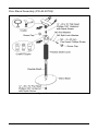
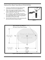
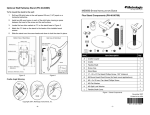
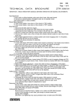
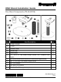
9590 Stand Installation Guide
Flex Stand Components (PN 46-00709)
Item
Item Description
Qty.
A
Cradle Coupler
1
B
Cradle
1
C
Flexible Shaft
1
D
Screw Cap
2
E
Stand Base
1
F
¼" - 20 x ⅜" Flat Head Phillips Screw, 100° Undercut with
Nylok
2
G
#8 Round Head Wood Screw (for fixed mount applications)
2
H
M3 -.5 x 20 mm, Pan Head Phillips Screw
1
J
M3 Flat Washer
1
K
M3 Split Lock Washer
1
L
Flexible Shaft Cover
1
Figure 1. Stand Components
00-05249 Rev C
2/12
1
Flex Stand Assembly (PN 46-00709)
Figure 2. Stand Assembly
2
Optional Flex Stand Fixed Mount (PN 46-00709)
1.
In the kit, two #8 wood screws have been
provided for fixed mount applications.
2.
When choosing the stand location, make
sure to consider the front orientation of the
stand (indicated in Figure 3).
3.
On a centerline, drill two #39 pilot holes in
the countertop spaced 125 mm (4.92") apart.
The stand base can be used as a guide for
the spacing of the pilot holes.
4.
Secure the stand base to the countertop with
the two #8 wood screws provided.
Figure 3.
Figure 4. Stand Base Hole Pattern (Not to Scale)
3
Optional Wall/Tabletop Stand (PN 46-00885)
To fix mount the stand to the wall:
1.
Drill two #39 pilot holes in the wall spaced 39 mm (1.54") apart on a
horizontal centerline.
2.
Install one #8 wood screw in each of the pilot holes, leaving a space
between the head of the screw and the wall surface.
3.
Locate the two slots marked as "A" on the stand base in Figure 5.
4.
Match the "A" slots on the stand to the heads of the installed wood
screws.
5.
Slide the stand over the screw heads and down to lock the stand in place.
Figure 5.
Figure 6.
Cradle Angle Warning
4