1
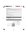
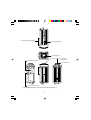
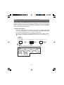
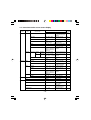
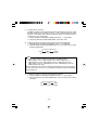
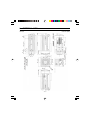
INSTRUCTION MANUAL
CCD COLOR CAMERA
IK-1000
Please read this manual thoroughly before use, and keep it handy
for future reference.
Record in space provided below the Model No. and
the Serial No. as found on the label on the bottom
of this unit.
Model. No. IK-1000 Serial No.
Retain this information for future reference.
TABLE OF CONTENTS
IMPORTANT SAFEGUARDS ................................................. 3
1. CAUTIONS ON USE AND INSTALLATION ................... 5
2. COMPONENTS ............................................................. 6
3. NAMES AND FUNCTIONS ........................................... 6
4. CONNECTION ............................................................. 10
5. LENS ADJUSTMENT .................................................. 11
6. OPERATION ................................................................ 13
7. MODE SETTING BY ON SCREEN DISPLAY ............. 17
8. TROUBLESHOOTING! ................................................ 32
9. EXTERNAL VIEW ........................................................ 33
10. SPECIFICATIONS ....................................................... 34
IMPORTANT SAFEGUARDS
1. Read Instructions
All the safety and operating instructions should be read
before the product is operated.
2. Retain Instructions
The safety instructions and instruction manual should
be retained for future reference.
3. Heed Warnings
All warnings on the product and in the instruction
manual should be adhered to.
4. Follow Instructions
All operating and use instructions should be followed.
5. Cleaning
Disconnect this video product from the power supply
before cleaning.
6. Attachments
Do not use attachments not recommended by the video
product manufacturer as they may cause hazards.
7. Water and Moisture
Do not use this video product near water-for example,
near a bath tub, wash bowl, kitchen sink, or laundry
tub, in a wet basement, or near a swimming pool and
the like.
8. Accessories
Do not place this video product on an unstable cart,
stand, tripod, bracket or table. The video product may
fall, causing serious injury to a child or adult, and
serious damage to the product. Use only with stand,
tripod, bracket, or table recommended by the
manufacturer, or sold with the video product. Any
mounting of the product should follow the
manufacturer’s instructions, and should use a mounting
accessory recommended by the manufacturer.
9. Ventilation
This video product should never be placed near or over
a radiator or heat register. This video product should
not be placed in a built-in installation such as a
bookcase or rack unless proper ventilation is provided
or the manufacturer’s instructions have been adhered
to.
10. Power Sources
This video product should be operated only from the
type of power source indicated on the marking label. If
you are not sure of the type of power supply to your
location, consult your product dealer.
11. Power-Cord Protection
Power-Supply cords should be routed so that they are
not likely to be walked on or pinched by items placed
upon or against them, paying particular attention to
cords at plugs, screws and the point where they exit
from the product.
12. Installation
This video product should be installed on a firm and
solid part of the ceiling or wall. If installed on a soft
and weak place, the camera unit may fall. A person
under it may be injured and things under it may be
damaged.
13. Lightning
For added protection for this video product during a
lightning storm, or when it is left unattended and
unused for long periods of time, unplug it from the wall
outlet and disconnect the power supply and cable
system. This will prevent damage to the video product
due to lightning and power-line surges. If lightning
occurs, do not touch the unit or any connected cables
in order to avoid electric shock.
14. Overloading
Do not overload power supply and extension cords as
this can result in a risk of fire or electric shock.
15. Object and Liquid Entry
Never push objects of any kind into this video product
through openings as they may touch dangerous
voltage points or short-out parts that could result in a
fire or electrical shock. Never spill liquid of kind on the
video product.
16. Servicing
Do not attempt to service this video product yourself
as opening or removing covers may expose you to
dangerous voltage or other hazards. Refer all servicing
to qualified service personnel.
17. Damage Requiring service
Disconnect this video product from the power supply
and refer servicing to qualified service personnel under
the following conditions.
a. When the power-supply cord or plug is damaged.
b. If liquid has been spilled, or objects have fallen into
the video product.
c. If the video product has been exposed to rain or
water.
d. If the video product does not operate normally by
following the operating instructions in the instruction
manual. Adjust only those controls that are covered
by the instruction manual as an improper adjustment
of other controls may result in damage and will often
require extensive work by a qualified technician to
restore the video product to its normal operation.
e. If the video product has been dropped or the cabinet
has been damaged.
f. When the video product exhibits a distinct change in
performance-this indicates a need for service.
18. Replacement Parts
When replacement parts are required, be sure the
service technician has used replacement parts
specified by the manufacturer with the same
characteristics as the original part. Unauthorized
substitutions may result in fire, electric shock or other
hazards.
19. Safety Check
Upon completion of any service or repairs to this video
product, ask the service technician to perform safety
checks to determine that the video product is in proper
operating condition.
-3-
CAUTION TO REDUCE THE RISK OF ELECTRIC SHOCK.
DO NOT REMOVE COVER (OR BACK).
NO USER SERVICEABLE PARTS INSIDE.
REFER SERVICING TO QUALIFIED SERVICE PERSONNEL.
The lightening flash with arrowhead
symbol, within an equilateral triangle,
is intended to alert the user to the
presence of uninsulated “dangerous
voltage” within the product’s enclosure
that may be of sufficient magnitude to
constitute a risk of electric shock to
persons.
The exclamation point within an
equilateral triangle is intended to alert
the user to the presence of important
operating and maintenance (servicing)
instructions in the literature
accompanying the appliance.
WARNING :
TO REDUCE THE RISK OF FIRE OR
ELECTRIC SHOCK, DO NOT EXPOSE
THIS APPLIANCE TO RAIN OR
MOISTURE.
CAUTION :
CONNECT 12V DC UL LISTED CLASS
2 POWER SUPPLY.
FIELD INSTALLATION :
WORDED : “THIS INSTALLATION
SHOULD BE MADE BY A QUALIFIED
SERVICE PERSON AND SHOULD
CONFORM TO ALL LOCAL CODES.”
FCC NOTICE
This equipment has been tested and found to comply with the limits for a Class A digital
device, pursuant to Part 15 of the FCC Rules. These limits are designed to provide reasonable
protection against harmful interference when the equipment is operated in a commercial
environment. This equipment generates, uses, and can radiate radio frequency energy and,
if not installed and used in accordance with the instruction manual, may cause harmful
interference to radio communications. Operation of this equipment in a residential area is
likely to cause harmful interference in which case the user will be required to correct the
interference at his own expense.
USER-INSTALLER CAUTION : Your authority to operate this FCC verified equipment could
be voided if you make changes or modifications not expressly approved by the party.
NOTICE
When the warning display "FAN STOP" appears on screen, contact your local representative
for replacement of the radiation fan.
A radiation fan is a consumable item. Even if the warning is not displayed, replace it every
30,000 hours as a guide. This service life is just a rule of thumb for replacement cycle and
does not assure the part's performance.
-4-
1. CAUTIONS ON USE AND INSTALLATION
• On installation, observe the following matters:
- Do not block the radiation fan's holes.
- Do not place cloth including a tablecloth over the fan.
- Do not place the camera on the carpet or cushion.
- Dot place the camera into a confined small room susceptible to heat generation.
Doing this would raise the internal temperature causing the fire.
• Carefully handle the units
Do not drop, or give a strong shock or vibration to the camera. This may cause problems. Treat
the camera cables carefully to prevent problems, such as cable breakdown.
• Do not shoot intense light
If there is an intense light at a location on the screen such as a spot light, blooming* 1 and smearing*2
may occur. When intense light enters, vertical stripes may appear on the screen. This is not a
malfunction. Ghosts may occur when there is an intense light near the object. In this case, change
the shooting angle.
• Install the camera in a location free from noise
If the camera or the cables are located near power utility lines such as TV, or PC related
equipments, undesirable noise may appear on the screen. In such case, try to change the
location or the cable wiring. If equipment originating radio waves, such as cell phone, comes
close to the camera, or the camera is installed near the relay antenna of such equipment, noise
may appear on the screen.
• Moire
When thin stripe patterns are shot, stripe patterns that are not actually there (moire) may
appear as interference stripes. This is not a malfunction.
• Operating ambient temperature and humidity
The operating ambient temperature ranges from 0°C to 50°C (32°F to 122°F) with humidity
from 30% to 90%, Do not use the camera in places where the temperature and humidity are
beyond the specified range. Picture quality will decrease and internal damage may occur.
• Be particularly careful when using places where temperature and humidity are high. When
continuously shooting in hot places for a long time, the life of the camera will be shortened due
to deterioration of parts.
• Outdoor installation
When using the camera outdoors, be sure to install the camera in a properly insulated enclosure.
For details, contact your nearest dealer.
• Prolonged non operation of the camera
If the camera is not used for a prolonged amount of time, disconnect the power supply.
*1: Blooming is a phenomenon where blur occurs around intense light.
*2: Smearing is a phenomenon where vertical stripes appear in the upper and lower areas of
intense light.
-5-
• When cleaning the camera
Unplug the power source before cleaning. Clean with a soft dry cloth. If the dust is hard to take
off, softly wipe off with a cloth soaked in mild detergent. Do not use volatile chemicals such as
thinner, benzene, and insecticide. If used, coating and printed letters may come off or may be
discolored. When cleaning the lens, use a lens cleaning paper etc.
• Preliminary confirmation of the location where the camera is installed (with a tripod not
used)
Before installing the camera, make sure that the location can withstand the total weight of the
camera.
If the camera is installed in places where the strength of bearing it is insufficient, secure the
structure by reinforcement etc., to bear the load.
If the reinforcement strength is insufficient, the camera may drop, causing personal injury and
malfunction.
• Handling of the protection cap
Keep the protection cap away from children. Children may put them into the mouth or swallow
them accidentally. Do not throw away the protection cap since it protects the image sensing
plane when lens is removed from the camera.
2. COMPONENTS
(1) Camera body ........................................................... 1
(2) Instruction manual ................................................... 1
3. NAMES AND FUNCTIONS
[Back]
r DISP button
t PAGE button
y MENU UP button
u MENU DOWN button
i DATA UP button
q DC IN 12V terminal
o DATA DOWN button
w VIDEO terminal
!0 S-VIDEO terminal
e RS232C terminal
-6-
!1 Camera Support Fitting
!2 IRIS terminal (4P)
!3 Imaging unit
!6 C mount ring
lock screw
!4 Tripod setting hole
!7 C mount ring
!5 Iris selection switch
* For detailed dimensions, refer to the external view on page 33.
-7-
q DC IN 12V terminal
Accepts a DC power unit (12 V).
w VIDEO terminal
Outputs VBS signal. Connected to monitor, recording device,
etc. (BNC connector)
e RS232C terminal
Used to control functions by communications via RS232C.
r DISP button
Used when switching the display.
t PAGE button
Used when switching to the setting screen and when selecting
the setting screens.
y MENU UP button
Selecting the function to be confirmed or changed on the setting
screen.
u MENU DOWN button
Selecting the function to be confirmed or changed on the setting
screen.
i DATA UP (AWB) button
Changes the setup contents of the function selected by the
MENU (UP/DOWN) button.
(Also used to perform ONE PUSH WB.)
o DATA DOWN button
Changes the setup contents of the function selected by the
MENU (UP/DOWN) button.
!0 S-VIDEO terminal
Outputs Y (brightness signal) and C (color signal).
!1 Camera Support Fitting
Fitting to fix the camera to the housing.
!2 IRIS terminal (4P)
Connected when using automatic iris lens.
!3 Image sensor
Equipped with imaging element. Carefully prevent dust, dirt,
fingerprint, etc.
Cautions
• Because the surface is coated, use a soft cloth when wiping. Using abrasives may
strip the coating.
-8-
!4 Tripod setting hole
Used when fixing a camera to the tripod.
Cautions
• When attaching the camera to a tripod, fasten the tripod to the camera tripod setting
hole without sliding them from each other. If not fixed securely, the camera may drop,
causing personal injury.
• Use a tripod screw that is between 4 mm and 8 mm in length.
!5 Iris selection switch
Select the types of automatic iris lenses (DC lens and Video
lens).
!6 C mount ring, lock screw
Locks back focus adjusting ring.
!7 C mount ring
Install the C mount lens.
-9-
4. CONNECTION
Monitor
Lens
VIDEO terminal
Camera body
Coaxial cable of 75Ω
DC IN 12V terminal
DC 12 V power supply
Cautions
• When installing the camera, unplug the power source of the camera and all connected
equipment.
• Please use a monitor which has BNC or S-Video input.
• A coaxial cable of 75Ω or S-Video cable is needed to connect a video monitor etc.
• For DC power supply connecting to DC 12 V terminal, use a power supply with the
specifications described below.
Power supply voltage: DC12V ±10%
Current rating:
2.0 A or more
Ripple voltage:
50 mV (p-p) or less
Connector:
HR10A—7P—4S by HIROSE Electronics Co., Ltd.
Pins 1, 2: +12V
Pins 3, 4: GND
(1) Install the lens to the camera body. For available lenses, refer to the item “5 LENS
ADJUSTMENT.”
(2) Connect a coaxial cable from the VIDEO terminal to the video input terminal of the
video monitor etc.
(3) Connect equipment, turn on the power supply to the camera, and then turn on the
power to the equipment.
(4) Adjust the lens by referring to item 5, obtain the best camera performance.
- 10 -
5. LENS ADJUSTMENT
5.1 Available Lens
Use a C mount lens whose rear flange projection is 9 mm or
less.
C mount
9 mm or less
Cautions
• When using a zoom lens or a lens of 400 g or more, be sure that the lens is supported
to prevent damage to the C mount ring. Refer to the instruction manual of the lens.
5.2 How to Adjust Iris
5.2.1 Automatic iris lens
When using a lens without iris amplifier (DC) or iris amplifier built-in lens (VIDEO), connect
a 4P iris connector to the 4P terminal on the side surface of the camera body, and then
change the iris switch at the bottom of the camera body according to the lens. (Factory
setting: DC)
[How to adjust DC lens]
To obtain appropriate exposure (brightness), adjust SENS setting on the screen display
menu.
For how to operate, refer to the items “7.1 Selecting Screen” and “7.3 Setting SENS
(Sensitivity).”
[How to adjust Video lens]
(1) Set the AUTO mode setting “LEVEL” to “0”, “Peak/AVE” to “AVERAGE” and “AREA to
PRESET”.
(2) Select MANUAL mode for the SENS page of the screen display menu (refer to 7.3.2).
(3) Set the lens to Average.
(4) While shooting an object exposed to light as equally as possible, adjust the lens to
obtain appropriate exposure (brightness). To do so, prevent extreme brightness or
darkness from entering the image.
If measuring instrument such as waveform monitor is available, adjust the white level
to 50% by adjusting the lens side while all white area is being shot.
(5) To make video image a little brighter or a little darker while shooting an actual object,
make adjustments by changing the “LEVEL” value of the setting item on SENS page
in the camera OSD menu.
- 11 -
Cautions
• Do not adjust the lens side in the adjustment in (5). Interference of exposure control
between lens and camera body may cause noisy video image and hunting.
1
3
2
4
Lens side
1
2
3
4
Video lens
Power supply
+9 V (50 mA maximum)
NC
Driving signal
GND
DC lens
Brake (–)
Brake (+)
Driving (+)
Driving (–)
Cautions
• Note that wrong selection of iris switch or wrong connection of iris connector causes
heating inside the camera, resulting in malfunction and failure.
5.3 How to Adjust Back Focus and field angle
At factory setting, back focus is set to its standard position. However, slight readjustments
may be needed depending on the type of zoom lens. Back focus is adjusted with the back
focus adjustment ring at the top of the camera so that distance of the object can correctly
meet the focus position of the lens when the lens is correctly installed.
For adjustment, loosen the mount ring lock screw with L-shape hexagon 1.3 mm wrench,
and then rotate the mount ring. After the adjustment is completed, tighten the screw.
- 12 -
6. OPERATION
q
w
e
r
Referring to the above item “4. CONNECTION,” connect necessary equipment.
Turn on the connected equipment and the power source of this camera.
Point the lens at the object, operate the lens iris adjustment, focus adjustment, etc.
Refer to the items “6.1 Sense Function,” “6.2 White Balance,” “6.3 SCENE file” and “7.
MODE SETTING BY ON SCREEN DISPLAY,” select the necessary items and perform
the operations.
6.1 SENS Function
This unit provides the SENS function to control lens iris and sensitivity, and adjust brightness
of video images. The SENS function is divided into the two modes described later: AUTO
and MANUAL. Each of them can be used combined with the controls described below.
• Lens automatic iris control:
Automatically controls the brightness by the automatic iris lens.
• Electronic multiplication (CMG) control:
The electronic multiplication function of EM-CCD (electronic multiplication CCD imaging
element) adopted in this camera controls the sensitivity inside the imaging element.
This control is characterized by noise lower than the circuit gain (AGC) control and the
sensitivity control with residual image far less than long term exposure. This control is
optimum with importance placed on the shooting of a moving subject.
• Circuit gain (AGC) control:
Controls the sensitivity of EM-CCD imaging element output in a subsequent circuit. We
suggest giving the highest possible priority to the electronic multiplication (CMG) control.
• Long term exposure control:
Controls the sensitivity of exposure time of EM-CCD imaging element by exposing for a
long time in units of two fields.
Though long term exposure (low shutter speed) causes residual image and/or blurring of
object, the sensitivity control of a stationary object makes noise lower than the electronic
multiplication (CMG) control or circuit gain (AGC) control.
This control is optimum for shooting stationary object with lower noise.
• Electronic shutter control:
Sets electronic shutter exposure time to control the sensitivity.
Two modes are available: MANUAL mode in which exposure time can be selected from
1/100s, 1/250s, 1/500s, 1/1000s, and 1/2000s, and Synchro. Scan mode where exposure
time can be set in units of horizontal scanning time (1 H) or in units of two fields. This
setting can be made in the MANUAL mode only.
- 13 -
6.1.1 AUTO Mode
In the AUTO mode, the brightness and sensitivity of video image can automatically be
controlled for each of four sensitivity controls according to the brightness of object.
In case of excess of individual sensitivity control ranges due to too bright or too dark object,
the status is automatically switched among four controls as shown in the diagram below to
control lens iris and sensitivity.
Electronic multiplication
(CMG) control
Lens automatic iris control
Long term exposure
(SS LONG) control
Circuit gain (AGC) control
If, for example, a very dark object is shot, the camera tries to control the brightness of the
video image by the lens automatic iris control first. However, if sufficient brightness is not
obtained even with the lens iris opened, the electronic multiplication (CMG) control is
automatically activated to control the sensitivity automatically. If sufficient brightness is not
obtained even with the maximum sensitivity of electronic multiplication (CMG) control, the
camera keeps the sensitivity of electronic multiplication (CMG) maximum, and automatically
activates the circuit gain (AGC) control to control the sensitivity automatically. If a sufficient
sensitivity is not yet obtained with the maximum circuit gain control, the camera keeps the
sensitivity of each of electronic multiplication (CMG) circuit and circuit gain (AGC) control
maximum, and finally activates long term exposure control to control the exposure time of
long term exposure automatically.
Electronic multiplication (CMG) control, circuit gain (AGC) control, and long term exposure
(SS LONG) control can set maximum sensitivity and maximum exposure time on the screen
display menu.
(Refer to the item “7.3.1 When Changing Setting of AUTO SENS Mode”)
6.1.2 MANUAL mode
In MANUAL mode, electronic multiplication (CMG) control, circuit gain (AGC) control, and
electronic shutter control are set to their fixed sensitivities on the screen display menu.
(Refer to the item “7.3.2 When Changing Settings of MANUAL mode and MANUAL Shutter
mode”)
As in the case of AUTO mode, only the lens automatic iris control is automatically controlled.
- 14 -
6.2 White Balance
For the white balance adjustment for this unit, ATW (Automatic Tracking White Balance),
ONE PUSH WB (One Push White Balance) and MANUAL (Manual White Balance)
adjustments are provided. To select the desired mode, refer to the item “7.4 WHT BAL
(White balance)” in the chapter “7. MODE SETTING BY ON SCREEN DISPLAY.”
ATW
(Automatic Tracking
White Balance)
ONE PUSH WB
(One Push White Balance)
MANUAL
(Manual white balance)
Outline
The camera automatically
measures color
temperature to adjust the
white balance.
Adjust the white balance
by pressing the [DATA UP]
button while shooting the
white object in an area set
on the ONE PUSH WB
setting screen.
While shooting a white
object, perform
adjustment on the WHT
BAL Setting Screen.
Feature
The camera automatically
traces changes in color
temperature to adjust the
white balance.
The accuracy is higher
than that of ATW. This is
appropriate to shooting
conditions where color
temperature does not
change so much.
Artificial white balance
can be set. This is
appropriate to shooting
conditions where color
temperature does not
change so much.
Remarks
If illumination condition is
not good, white balance
may not be obtained.
Perform adjustments by
confirming with a monitor
or a vector scope.
6.2.1 ONE PUSH WB (One Push White Balance)
• Set the MODE to ONE PUSH WB on the WHT BAL setting screen. (Refer to the item
“7.4.1 “WHT BAL (White Balance)””)
• If the screen displays a color bar and the index/setting screen is displayed, press the
[DISP] button to clear the color bar and character display on the setting screen.
• Shoot a white object that fills the screen set on the AWB setting screen (refer to the item
“7.4.1 (3) “Changing ONE PUSH WB area””) and then press the [DATA UP] button for
approximately one second.
• The character AWB blinks when the AWB operation starts.
• The character AWB stops blinking when the AWB operation finishes, and the result is
displayed for approximately one second.
- 15 -
Display
Meaning
AWB OK
Automatic white balance adjustment finished correctly.
AWB NG
LEVEL LOW
Automatic white balance adjustment cannot be performed because the video level
is too low.
Adjust the camera for a proper video level.
AWB NG
LEVEL HIGH
Automatic white balance adjustment cannot be performed because the video level
is too high.
Adjust the camera for a proper video level.
AWB NG OUT Automatic white balance adjustment cannot be performed because the color
OF RANGE
temperature of the light source is out of the adjustable range.
If the message appears, change the illumination or use a color temperature
conversion filter.
AWB NG
Automatic white balance adjustment cannot be performed for other reasons (such
as no white area is included in an object).
6.2.2 MANUAL (Manual white balance)
• Set the MODE to MANUAL on the WHT BAL setting screen. (Refer to the item “7.4 “WHT
BAL (White Balance)””)
• Shoot a white object, and adjust the white balance by adjusting R GAIN and B GAIN on
the setting screen while confirming with a monitor or a vector scope.
(Refer to the item “7.4.3 When Changing Settings in MANUAL (manual white balance
mode)”)
6.3 SCENE files
This unit has three SCENE files A, B and C selectable according to the shooting conditions.
• Select a scene set up on the OPTION screen (refer to the item 7.6 (2) “To change settings
of SCENE files”).
In this case, the set contents written into internal memory of this camera are loaded.
• After that, each time setting is changed on the screen display, the contents of the change
are written into memory and memorized even if the power source is turned off.
• To set SCENE files to factory setting status, press both the [MENU DOWN] and [DATA
DOWN] buttons at a time for approximately five seconds while the screen display and
color bar are turned off. The character “RESET OK” is displayed for approximately one
second, and the selected SCENE file is initialized to factory setting status.
- 16 -
7. MODE SETTING BY ON SCREEN DISPLAY
Various settings can be controlled on the unit by using the on screen menu displayed on the
monitor. The contents once set are memorized in the SCENE files (A, B and C) even if the power
source is turned off. So it is unnecessary to set again when using the camera next time. When the
setting is performed, select the setting screen of the item to be set. A selected SCENE file
appears upper right on the setting screen.
7.1 Using the Screens
Each screen (video signal screen, color bar screen, index screen, setting screen or area
screen) can be displayed by using the [DISP], [PAGE], [MENU UP], [MENU DOWN], [DATA
UP], or [DATA DOWN] button on the rear side of the camera body.
A screen is selected when pressing the [PAGE] button after moving “→” on the screen
by the [MENU UP] or [MENU DOWN] button while the index screen is displayed.
POWER
ON
Video signal output
Color bar screen
DISP
DISP
Index menu
DISP
PAGE
DISP
PAGE
PAGE
Menus
PAGE
1. SENS
2. WHT BAL
PAGE
3. PROCESS
PAGE
PAGE
AUTO
ATW
MANUAL
ONE PUSH
WB
4. OPTION
MANUAL
- 17 -
7.2 Items that can be set on screen display
Page
name
1 SENS
Mode
name
AUTO
MANUAL
2 WHT BAL
Content
FLICKER
ON/OFF
Flicker-less mode
OFF
(1/100s electronic shutter)
ON/OFF
CMG MAX
OFF, CMG1, CMG2, ...,
CMG10
Maximum electronic
multiplication gain
CMG9
AGC MAX
OFF, 1dB, 2dB, ...,
18dB
Maximum circuit gain
OFF
SS LONG MAX
OFF, 2FLD, 4FLD, ...,
254FLD, 256FLD
Number of long term
exposure fields
OFF
LEVEL
-100, -99, ..., 0, 1, ..., 100 SENS photometric level
0
PEAK/AVE
PEAK/AVERAGE
PEAK photometry/
average photometry
AVERAGE
AREA
PRESET A, PRESET B,
PRESET C, PRESET D,
PRESET E, PRESET F,
PRESET G
Photometric area
selection
PRESET A
SHUTTER
MANUAL
MANUAL
OFF, 1/100s, 1/250s,
Electronic shutter speed OFF
1/500s, 1/1000s, 1/2000s
SS
SYNCHRO 9/262.5H, 10/262.5H, ...,
SCAN
255/262.5H, OFF, 2FLD,
4FLD, 6FLD, ..., 256FLD
Synchro. scan, exposure OFF
time of long term
exposure
CMG
OFF, CMG1, CMG2, ...,
CMG10
Electronic multiplication
gain
OFF
GAIN
OFF, 1dB, 2dB, ..., 18dB
Circuit gain
0dB
-10, -9, ..., 0, 1, ..., 10
R offset of automatic
tracking white balance
0
B PAINT
-10, -9, ..., 0, 1, ..., 10
B offset of automatic
tracking white balance
0
R PAINT
-10, -9, ..., 0, 1, ..., 10
R offset of one push
white balance
0
B PAINT
-10, -9, ..., 0, 1, ..., 10
B offset of one push
white balance
0
AREA
PRESET A, PRESET B,
PRESET C, PRESET D,
PRESET E, PRESET F,
PRESET G
Photometric area
selection
PRESET A
R GAIN
-110, -109, ..., 0, ..., 204
R gain adjustment
0
B GAIN
-250, -249, ..., 0, ..., 256
B gain adjustment
0
GAMMA
ON/OFF
Gamma ON/OFF
ON
DTL
ON/OFF
Detail ON/OFF
ON
BAUD RATE
19200bps/9600bps
RS232C communication 19200bps
speed
SCENE FILE
A, B, C
Switching of scene file in A
which setting is
memorized
TEMP. ALARM
ON/OFF
Warning function for set
temperature increase
ON
CMG OFFSET
0, 1, ..., 100
Offset adjustment of
electronic multiplication
0
MANUAL
4 OPTION
Parameter
Preset
(factory setting)
status
R PAINT
ATW
ONE
PUSH WB
3 PROCESS
Set content
Set item name
- 18 -
7.3 SENS (sensitivity setting)
The sensitivity of this unit can be se to AUTO and MANUAL.
Place the cursor “→” on MODE, press the [DATA UP] or [DATA DOWN] button, and select
the desired mode from AUTO and MANUAL.
AUTO:
Automatically control the exposure time to get the set level.
MANUAL: The camera operates with the fixed sensitivity. Lens automatic iris control
function works except when long term exposure is set.
7.3.1 When Changing Setting of AUTO SENS Mode
Up/down movement
by MENU UP/DOWN
Set by DATA
UP/DOWN
・SENS mode
AUTO, MANUAL
・Display of SCENE file
-- 1 SENS -MODE AUTO
FLICKER
CMG MAX
AGC MAX
SS LONG MAX
LEVEL
PEAK/AVE
AREA
<SENS MODE=AUTO>
<FILE A>
・Flicker correction
ON, OFF
・Setting of maximum value of
OFF, CMG1, CMG2, …, CMG10
AUTO electronic multiplication
OFF
CMG5
OFF
OFF
0
AVERAGE
PRESET A
・Setting of maximum value of
AUTO circuit gain
OFF, 1dB, 2dB, …, 18dB
・Setting of maximum value of
OFF, 2FLD, 4FLD, …, 256FLD
AUTO long term exposure
・Adjustment of AUTO SENS
-100, -99, …, 0, 1, …, 100
level
・Brightness detection, average AVERAGE, PEAK
value, peak mode selection
・Selection of brightness
detection area
- 19 -
PRESET A, PRESET B,
PRESET C, PRESET D,
PRESET E, PRESET F,
PRESET G
(1) Changing flicker correction
FLICKER is capable of correcting fluorescent flicker generated in 50 Hz area. Setting
FLICKER to ON fixes the electronic shutter to 1/100s, removing fluorescent flicker.
However, if AUTO SENS enters long term exposure control, the electronic shutter is
switched from 1/100s to long term.
q Using the [MENU UP] or [MENU DOWN] button, place “→” on FLICKER.
w Using the [DATA UP] or [DATA DOWN] button, select ON or OFF.
(2) Changing the setting of maximum value of AUTO electronic multiplication
q Using [MENU UP] or [MENU DOWN] button, place “→” on CMG MAX.
w Using the [DATA UP] or [DATA DOWN] button, set the maximum value of AUTO
electronic multiplication.
Increase by [DATA UP]
OFF
CMG1
CMG10
Decrease by [DATA DOWN]
Note
At factory setting, CMG1 to CMG10 are adjusted to the following gains.
CMG1: approx. 2 times, CMG2: approx.4 times, CMG3: approx.8 times,
CMG4: approx.16 times, CMG5: approx.32 times, CMG6: approx.63 times,
CMG7: approx.125 times, CMG8: approx.250 times, CMG9: approx. 500 times,
CMG10: approx.1000 times
However, aging may cause changes in the gains, depending on the CCD characteristics.
In such cases, please refer to 7.6 (4) Changing the setting of electronic multipliation
offset, on page 30.
(3) Changing the setting of maximum value of AUTO circuit gain
q Using the [MENU UP] or [MENU DOWN] button, place “→” on AGC MAX.
w Using the [DATA UP] or [DATA DOWN] button, set the maximum value of AUTO
circuit gain.
Increase by [DATA UP]
OFF
1dB
18dB
Decrease by [DATA DOWN]
- 20 -
(4) Changing the setting of maximum value of AUTO long term exposure
q Using the [MENU UP] or [MENU DOWN] button, place “→” on SS LONG MAX.
w Using the [DATA UP] or [DATA DOWN] button, set the maximum value of AUTO
long term exposure.
Increase by [DATA UP]
OFF
2FLD
256FLD
Decrease by [DATA DOWN]
(5) Changing the SENS level adjustment
q Using the [MENU UP] or [MENU DOWN] button, place “→” on LEVEL.
w Using the [DATA UP] or [DATA DOWN] button, set the SENS level.
Increase by [DATA UP]
–100
0
100
Decrease by [DATA DOWN]
(6) Changing brightness detection, average value, peak mode selection
q Using the [MENU UP] or [MENU DOWN] button, place “→” on PEAK/AVE.
w Using the [DATA UP] or [DATA DOWN] button, select PEAK or AVERAGE.
- 21 -
(7) Changing brightness detection area
q Using the [MENU UP] or [MENU DOWN] button, place “→” on AREA.
w Using the [DATA UP] or [DATA DOWN] button, select PEAK or AVERAGE.
[DATA UP]
PRESET A
PRESET B
PRESET C
PRESET D
[DATA DOWN]
PRESET E
PRESET A
PRESET B
PRESET C
PRESET E
PRESET F
PRESET G
* Bold face on the diagram shows a detection area.
- 22 -
PRESET F
PRESET G
PRESET D
7.3.2 When Changing Settings of MANUAL mode and MANUAL Shutter mode
Up/down movement
by MENU UP/DOWN
Set by DATA
UP/DOWN
・Display of SCENE file
-- 1 SENS --
<FILE A>
MODE MANUAL
SHUTTER MANUAL
MANUAL
CMG
GAIN
LEVEL
PEAK/AVE
AREA
1/100s
CMG7
OFF
0
AVERAGE
PRESET A
・SENS mode
AUTO, MANUAL
・Electronic shutter mode
MANUAL, SS
・Electronic shutter speed
OFF, 1/100s, 1/250s, 1/500s,
1/1000s, 1/2000s
・Electronic multiplication gain
OFF, CMG1, CMG2, …, CMG10
・Circuit gain
OFF, 1dB, 2dB, …, 18dB
<SENS MODE=MANUAL, SHUTTER MODE=MANUAL>
(1) Changing electronic shutter speed
q Using the [MENU UP] or [MENU DOWN] button, place “→” on MANUAL.
w Using the [DATA UP] or [DATA DOWN] button, set the electronic shutter speed.
OFF
1/100s
[DATA UP]
1/250s 1/500s 1/1000s
[DATA DOWN]
1/2000s
(2) Changing the setting of electronic multiplication gain
q Using the [MENU UP] or [MENU DOWN] button, place “→” on CMG.
w Using [DATA UP] or [DATA DOWN] button, set the electronic multiplication gain.
Increase by [DATA UP]
OFF
CMG1
CMG10
Decrease by [DATA DOWN]
(3) Changing the setting of circuit gain
q Using the [MENU UP] or [MENU DOWN] button, place “→” on GAIN.
w Using [DATA UP] or [DATA DOWN] button, set the circuit gain.
Increase by [DATA UP]
OFF
1dB
18dB
Decrease by [DATA DOWN]
- 23 -
7.3.3 When Changing Settings of MANUAL mode (Synchro. Scan mode)
Up/down movement
by MENU UP/DOWN
Set by DATA
UP/DOWN
・Display of SCENE file
-- 1 SENS --
<FILE A>
MODE MANUAL
SHUTTER SS
SYNCRO SCAN
CMG
GAIN
LEVEL
PEAK/AVE
AREA
30FLD
OFF
OFF
0
AVERAGE
PRESET A
・SENS mode
AUTO, MANUAL
・Electronic shutter mode
MANUAL, SS
・Synchro. Scan shutter speed 9/262.5H, 10/262.5H, …, 255/262.5H,
OFF, 2FLD, 4FLD, 6FLD, …, 256FLD
・Electronic multiplication gain OFF, CMG1, CMG2, …, CMG10
・Circuit gain
OFF, 1dB, 2dB, …, 18dB
<SENS MODE=MANUAL, SHUTTER MODE=SS>
(1) Changing the setting of Synchro. Scan shutter speed
q Using the [MENU UP] or [MENU DOWN] button, place “→” on SYNCHRO SCAN.
w Using the [DATA UP] or [DATA DOWN] button, select the shutter speed.
9/262.5H
[DATA UP]
255/262.5H
OFF
2FLD
256FLD
[DATA DOWN]
Long term
exposure
* Electronic multiplication gain and circuit gain can be set as in the case of MANUAL
electronic shutter mode. (Refer to 7.3.2 (2)/(3))
Note
When setting the MANUAL long term exposure, the automatic iris cannot used.
- 24 -
7.4 WHT BAL (White Balance)
WHT BAL has three modes: ONE PUSH WB, ATW and MANUAL.
Place the cursor “->” on MODE, press the [DATA UP] or [DATA DOWN] button, and select the
desired mode from ONE PUSH WB, ATW, MANUAL.
7.4.1 When Changing Setting of ONE PUSH WB (One Push White Balance) Mode
Up/down movement
by MENU UP/DOWN
Set by DATA
UP/DOWN
・Display of SCENE file
-- 2 WHT BAL --
<FILE A>
MODE ONE PUSH WB
R PAINT
0
B PAINT
0
AREA
PRESET A
・WHT BAL mode
ONE PUSH WB, ATW, MANUAL
・R RAINT (offset) adjustment
-10 ∼ 10
・B RAINT (offset) adjustment
-10 ∼ 10
・Electronic multiplication gain
PRESET A, PRESET B,
PRESET C, PRESET D,
PRESET E, PRESET F,
PRESET G,
(1) Changing R PAINT (red offset)
q Using the [MENU UP] or [MENU DOWN] button, place “→” on R PAINT.
w Use the [DATA UP] or [DATA DOWN] button to make setting.
–10
Decrease in red
Increase in red
[DATA UP]
0
10
[DATA DOWN]
(2) Changing R PAINT (blue offset)
q Using the [MENU UP] or [MENU DOWN] button, place “→” on B PAINT.
w Use the [DATA UP] or [DATA DOWN] button to make setting.
–10
Decrease in blue
Increase in blue
[DATA UP]
0
10
[DATA DOWN]
- 25 -
(3) Changing ONE PUSH WB area
q Using the [MENU UP] or [MENU DOWN] button, place “→” on AREA
w Using the [DATA UP] or [DATA DOWN] button, set the photometer area.
PRESET A
PRESET B
PRESET C
PRESET E
PRESET F
PRESET G
* Bold face on the diagram shows a detection area.
- 26 -
PRESET D
7.4.2 When Changing Settings of ATW (Automatic Tracking White Balance) Mode
Up/down movement
by MENU UP/DOWN
Set by DATA
UP/DOWN
・Display of SCENE file
-- 2 WHT BAL ATW -- <FILE A>
MODE ATW
R PAINT
B PAINT
0
0
・WHT BAL mode
ONE PUSH WB, ATW, MANUAL
・R RAINT (offset) adjustment
-10 ∼ 10
・B RAINT (offset) adjustment
-10 ∼ 10
(1) Changing R PAINT (red offset)
q Using the [MENU UP] or [MENU DOWN] button, place “→” on R PAINT.
w Use the [DATA UP] or [DATA DOWN] button to make setting.
–10
Decrease in red
Increase in red
[DATA UP]
0
10
[DATA DOWN]
(2) Changing R PAINT (blue offset)
q Using the [MENU UP] or [MENU DOWN] button, place “→” on B PAINT.
w Use the [DATA UP] or [DATA DOWN] button to make setting.
–10
Decrease in blue
Increase in blue
[DATA UP]
0
10
[DATA DOWN]
- 27 -
7.4.3 When Changing Settings of MANUAL (Manual White Balance) Mode
Up/down movement
by MENU UP/DOWN
Set by DATA
UP/DOWN
・Display of SCENE file
-- 2 WHT BAL --
<FILE A>
・WHT BAL mode
MODE MANUAL
R GAIN
B GAIN
ONE PUSH WB, ATW, MANUAL
・Red gain adjustment -110, -109, …, 0, 204
0
0
・Blue gain adjustment -250, -249, …, 0, 256
(1) Changing red gain
q Using the [MENU UP] or [MENU DOWN] button, place “→” on R GAIN.
w Use the [DATA UP] or [DATA DOWN] button to make setting.
–110
Decrease in red
Increase in red
[DATA UP]
0
204
[DATA DOWN]
(2) Changing blue gain
q Using the [MENU UP] or [MENU DOWN] button, place “→” on B GAIN.
w Use the [DATA UP] or [DATA DOWN] button to make setting.
–250
Decrease in blue
Increase in blue
[DATA UP]
0
256
[DATA DOWN]
- 28 -
7.5 PROCESS (Process)
Up/down movement
by MENU UP/DOWN
Set by DATA
UP/DOWN
・Display of SCENE file
-- 3 PROCESS -GAMMA
DTL
<FILE A>
ON
ON
・Gamma correction
ON, OFF
・Detail
ON, OFF
(1) Changing ON/OFF of gamma correction
q Using the [MENU UP] or [MENU DOWN] button, place “→” on GAMMA.
w Using [DATA UP] or [DATA DOWN] button, select ON or OFF.
(2) Changing ON/OFF of detail
q Using the [MENU UP] or [MENU DOWN] button, place “→” on DTL.
w Using [DATA UP] or [DATA DOWN] button, select ON or OFF.
- 29 -
7.6 OPTION (Option)
Up/down movement
by MENU UP/DOWN
Set by DATA
UP/DOWN
・Display of SCENE file
-- 4 OPTION -BAUD RATE
SCENE FILE
TEMP.ALARM
CMG OFFSET
<FILE A>
19200bps
A
ON
0
・Setting RS232C communication 19200bps, 9600bps
baud rate
・Setting SCNE file
A, B, C
・Setting of temperature warning
ON, OFF
・Electronic multiplication offset 0∼100
(1) Changing communication baud rate
q Using the [MENU UP] or [MENU DOWN] button, place “→” on BAUD RATE.
w Using the [DATA UP] or [DATA DOWN] button, select 9600 bps or 19200 bps.
(2) Changing the setting of SCENE file
q Using the [MENU UP] or [MENU DOWN] button, place “→” on XCENE FILE.
w Using the [DATA UP] or [DATA DOWN] button, select A, B or C.
(3) Changing the setting of temperature warning
This unit provides a function of detecting abnormal increase of internal temperature.
When abnormal temperature increase is detected, the warning indicator “TEMP”
appears on the display. Power consumption is lowered by stopping CCD cooling circuit.
The internal detection temperature is set to a temperature, as a guideline, at which
the cabinet temperature is assumed to be approximately 70 to 75°C (158 to 167°F).
To avoid using this function in the practical environment, the function can be set to off.
q Using the [MENU UP] or [MENU DOWN] button, place “→” on TEMP. ALARM.
w Using the [DATA UP] or [DATA DOWN] button, select ON or OFF.
- 30 -
(4) Changing the setting of electronic multiplication offset
q Using the [MENU UP] or [MENU DOWN] button, place “→” on CMG OFFSET.
w Use the [DATA UP] or [DATA DOWN] button to make setting.
Decrease of gain
[DATA UP]
0
100
[DATA DOWN]
Increase of gain
Cautions
This function is provided to correct gain that has changed due to CCD aging. Do not
use this function unless the gain has changed.
- 31 -
8. TROUBLESHOOTING!
Symptom
Where to check
Video image does
not appear.
•
•
•
•
•
•
Is the iris selection switch set correctly according to the lens?
Is the lens iris adjustment correct?
Are cables connected correctly?
Is power supplied to equipment and camera body?
Is SENS mode set correctly?
Is the correct video monitor selected?
Color is not correct.
• Is the video monitor adjusted correctly?
• Is illumination dark?
Be sure to inspect CCD camera that have been used for a prolonged period of time
While operating the camera, are there any
symptoms as shown below?
<Stop of use>
• Video image does not appear even when
power supply is turned on.
• Power supply plug and cord are heated
abnormally.
• There is peculiar smell or strange noise.
• Water or foreign material enters.
• Smoke comes out.
• Other defects or failures occur.
In such cases, turn off the power supply to
prevent failures and accidents, and unplug
the power source. Be sure to contact your
dealer for inspection and repair. Do not
attempt to repair the product yourself.
- 32 -
45.75 (1.80)
- 33 .5
3
4-R
)
14
(0.
7 (0.28)
35 (1.38)
58 (2.28)
C-MOUNT RING
ø 28
27.8 (1.09)
2
R7
19
5
(0.75)(0.20)
CD LEVEL 25.34 (1.00)
48.34 (1.90)
58.4 (2.30)
40 (1.57)
C-MOUNT RING LOCK SCREW
12.8 (0.50)
RATING LABEL
22
(0.87)
IK-1000
94.35 (3.71)
1/4-20 UNC
133 (5.24)
79.25 (3.12)
9. EXTERNAL VIEW
Unit: mm (inch)
10. SPECIFICATIONS
Power supply
DC12V ±10% (4P connector HR10A-7P-4PB by HIROSE Electronics Co., Ltd.)
Power consumption
6.0 W (with ambient temperature of 77°F) 12 W (with ambient temperature of 113°F)
Imaging element
1/2 type 330K pixels (effective pixels) frame interline CCD
Effective number of pixels
H: 658 V: 496
Scanning system
2:1 interlace
Scanning frequency
Horizontal: 15.734 kHz, vertical: 59.94Hz
Synchronous system
Internal
Resolution
Horizontal: 420 TV lines/Vertical 350 TV lines
Minimum subject intensity
0.001 lx (electronic multiplication of 1000 times, AGC 12 dB, F1.2)*1
S/N
50 dB or more (standard sensitivity, AGC OFF)*1
Video image output
VBS 1.0 V (p-p) NTSC, 75Ω unbalance, Y/C 75Ω unbalance S terminal
External synchronous input
Unavailable
White balance
ATW/ONE PUSH WB/MANU (adjustable 2800K to 10000K)
ATW
R, B offset adjustable
ONE PUSH WB
Area settable (selected from 7 modes) R, B offset adjustable
MANU
R, B level adjustment
Electronic shutter
1/100s, 1/250s, 1/500s, 1/1000s, 1/2000s
MANU/Synchro. Scan (adjustable)
MANU
OFF (1/60s), 1/100, 1/250, 1/500, 1/1000, 1/2000
Synchro. Scan
9/262.5H to 255/262.5H, OFF, 2 FIELD to 256 FIELD
Electronic multiplication
Approximately 1000 times at maximum (AUTO/MANU setting)
AGC
OFF (0 dB), 1 dB, 2 dB, ..., 18 dB
Long term exposure
2, 4, 6, 8, 10, 12, ..., 254, 256 times (AUTO/MANU setting)
Automatic sensitivity selection
Allowable with an upper value setting of the magnification of the above electronic high sensitivity
Lens mount
C-Mount (not included)
Iris selection
DC/Video (switchable) (Factory setting: DC)
Iris adjustment
Available (OSD menu setting)
Backlight compensation
16 areas, 7 modes selectable
Remote control
Available with RS-232C terminal*2
Operation temperature
32°F to 122°F with humidity of 90% or less
Optimal temperature
32°F to 113°F
Storage temperature
–4°F to +140°F/Humidity of 70% or less
Dimension
2.28 × 2.30 × 5.24 (W × H × D, inch: excluding mounting block and terminals)
Weight
Approximately 1 lb. (excluding mounting block)
*1: Measured value with halogen lamp of 1:3000K.
*2: To use remote control function, contact your dealer.
• The designs and specifications are subject to change without notice.
- 34 -
- 35 -
- 36 -
- 37 -
- 38 -
- 39 -
One (1) Year
one (1) year
one (1) year
deliver
If technical support determines unit is defective, RMA will be issued with return instructions for repair.
You must notify (877) 855-1349 within (30) days after you discover that the product does not perform in accordance with
specifications during the Limited Warranty period.
All warranty service of this product must be performed by the Toshiba Exchange Center by calling (877) 855-1349.
Warranty service can not be performed by any other Toshiba Authorized Service Provider.
one (1) year