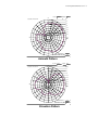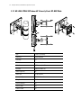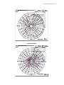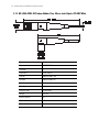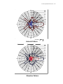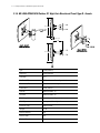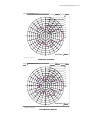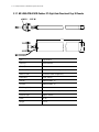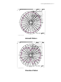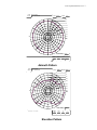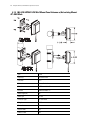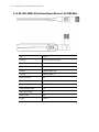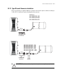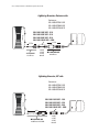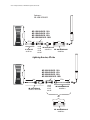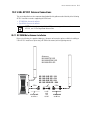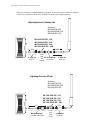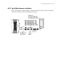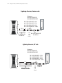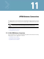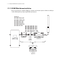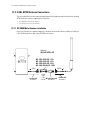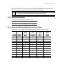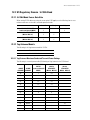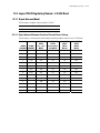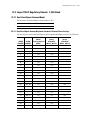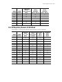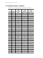
1
M
Enterprise Wireless LAN Antenna
Specification Guide
Version 1.7 November 2010
© 2010 Motorola, Inc. All rights reserved.
MOTOROLA and the Stylized M Logo are registered in the US Patent & Trademark Office. Symbol is a registered
trademark of Symbol Technologies, Inc. All other product or service names are the property of their respective owners.
Contents
Chapter 1. Antenna Selection and Description
1.1 Antenna Selection. . . . . . . . . . . . . . . . . . . . . . . . . . . . . . . . . . . . . . . . . . . . . . . . . . . . . . . . . . . . . . . . . . . . . . . . . . . . . 1-1
1.2 Antenna Selection Criteria. . . . . . . . . . . . . . . . . . . . . . . . . . . . . . . . . . . . . . . . . . . . . . . . . . . . . . . . . . . . . . . . . . . . . . 1-6
1.3 Antenna Accessories for Motorola Enterprise WLANs . . . . . . . . . . . . . . . . . . . . . . . . . . . . . . . . . . . . . . . . . . . . . . . . 1-7
Chapter 2. Product Compatibility
2.1 FCC/USA Compatibility . . . . . . . . . . . . . . . . . . . . . . . . . . . . . . . . . . . . . . . . . . . . . . . . . . . . . . . . . . . . . . . . . . . . . . . . . 2-1
2.2 Antenna Suite Summary . . . . . . . . . . . . . . . . . . . . . . . . . . . . . . . . . . . . . . . . . . . . . . . . . . . . . . . . . . . . . . . . . . . . . . . . 2-3
Chapter 3. 2.4 GHz Single Band Antenna Suite
3.1 Supported 802.11b/g/n Antenna Suite . . . . . . . . . . . . . . . . . . . . . . . . . . . . . . . . . . . . . . . . . . . . . . . . . . . . . . . . . . . . . 3-1
Chapter 4. 5.2 Ghz Single Band Antenna Suite
4.1 Supported 802.11a/n Antenna Suite . . . . . . . . . . . . . . . . . . . . . . . . . . . . . . . . . . . . . . . . . . . . . . . . . . . . . . . . . . . . . . 4-1
Chapter 5. 2.4GHz - 5.2GHz Dual Band Antenna Suite
5.1 Supported 802.11a/b/g/n Dual Band Antennas . . . . . . . . . . . . . . . . . . . . . . . . . . . . . . . . . . . . . . . . . . . . . . . . . . . . . . 5-1
Chapter 6. Antenna Cables
6.1 Supported Antenna Cables . . . . . . . . . . . . . . . . . . . . . . . . . . . . . . . . . . . . . . . . . . . . . . . . . . . . . . . . . . . . . . . . . . . . . . 6-1
Chapter 7. Supported Antenna Adapters
7.1 Supported Adapters . . . . . . . . . . . . . . . . . . . . . . . . . . . . . . . . . . . . . . . . . . . . . . . . . . . . . . . . . . . . . . . . . . . . . . . . . . . 7-1
Chapter 8. Supported Lightning Arrestors
8.1 Lightning Arrestors . . . . . . . . . . . . . . . . . . . . . . . . . . . . . . . . . . . . . . . . . . . . . . . . . . . . . . . . . . . . . . . . . . . . . . . . . . . . 8-1
Chapter 9. Mounting Kits
9.1 Mounting Kit Support . . . . . . . . . . . . . . . . . . . . . . . . . . . . . . . . . . . . . . . . . . . . . . . . . . . . . . . . . . . . . . . . . . . . . . . . . . 9-1
Chapter 10. AP-5131 Antenna Connections
10.1 2.4 GHz AP-5131 Antenna Connections . . . . . . . . . . . . . . . . . . . . . . . . . . . . . . . . . . . . . . . . . . . . . . . . . . . . . . . . . . . 10-2
10.2 5 GHz AP-5131 Antenna Connections. . . . . . . . . . . . . . . . . . . . . . . . . . . . . . . . . . . . . . . . . . . . . . . . . . . . . . . . . . . . . 10-9
TOC-2 Enterprise Wireless LAN Antenna Specification Guide
Chapter 11. AP300 Antenna Connections
11.1 2.4 GHz AP300 Antenna Connections . . . . . . . . . . . . . . . . . . . . . . . . . . . . . . . . . . . . . . . . . . . . . . . . . . . . . . . . . . . . . 11-1
11.2 5 GHz AP300 Antenna Connections . . . . . . . . . . . . . . . . . . . . . . . . . . . . . . . . . . . . . . . . . . . . . . . . . . . . . . . . . . . . . . 11-8
Chapter 12. AP 7131 Transmit Power
12.1
12.2
12.3
12.4
12.5
Configuring the AP 7131 Series Transmit Power . . . . . . . . . . . . . . . . . . . . . . . . . . . . . . . . . . . . . . . . . . . . . . . . . . . . 12-1
US Regulatory Domain 2.4 GHz Band . . . . . . . . . . . . . . . . . . . . . . . . . . . . . . . . . . . . . . . . . . . . . . . . . . . . . . . . . . . . 12-8
US Regulatory Domain 5.2 GHz Band . . . . . . . . . . . . . . . . . . . . . . . . . . . . . . . . . . . . . . . . . . . . . . . . . . . . . . . . . . . 12-13
Japanese TELEC Regulatory Domain 2.4 GHz Band . . . . . . . . . . . . . . . . . . . . . . . . . . . . . . . . . . . . . . . . . . . . . . . . 12-23
Japan TELEC Regulatory Domain 5.2 GHz Band . . . . . . . . . . . . . . . . . . . . . . . . . . . . . . . . . . . . . . . . . . . . . . . . . . . 12-27
Chapter 13. AP650 Regulatory Domains
13.1
13.2
13.3
13.4
13.5
13.6
US Regulatory Domain 2.4 GHz Band. . . . . . . . . . . . . . . . . . . . . . . . . . . . . . . . . . . . . . . . . . . . . . . . . . . . . . . . . . . . . 13-1
US Regulatory Domain 5 GHz Band. . . . . . . . . . . . . . . . . . . . . . . . . . . . . . . . . . . . . . . . . . . . . . . . . . . . . . . . . . . . . . 13-7
Japan TELEC Regulatory Domain 2.4 GHz Band . . . . . . . . . . . . . . . . . . . . . . . . . . . . . . . . . . . . . . . . . . . . . . . . . . . 13-19
Japan TELEC Regulatory Domain 5 GHz Band . . . . . . . . . . . . . . . . . . . . . . . . . . . . . . . . . . . . . . . . . . . . . . . . . . . . 13-25
EU Regulatory Domain 2.4 GHz Band . . . . . . . . . . . . . . . . . . . . . . . . . . . . . . . . . . . . . . . . . . . . . . . . . . . . . . . . . . . 13-37
EU Regulatory Domain 5 GHz Band. . . . . . . . . . . . . . . . . . . . . . . . . . . . . . . . . . . . . . . . . . . . . . . . . . . . . . . . . . . . . 13-43
Chapter 14. RFS4011 Regulatory Domains
14.1
14.2
14.3
14.4
14.5
14.6
US Regulatory Domain 2.4 GHz Band . . . . . . . . . . . . . . . . . . . . . . . . . . . . . . . . . . . . . . . . . . . . . . . . . . . . . . . . . . . . . 14-1
US Regulatory Domain 5 GHz Band. . . . . . . . . . . . . . . . . . . . . . . . . . . . . . . . . . . . . . . . . . . . . . . . . . . . . . . . . . . . . . . 14-5
Canada Regulatory Domain 2.4 GHz Band . . . . . . . . . . . . . . . . . . . . . . . . . . . . . . . . . . . . . . . . . . . . . . . . . . . . . . . . 14-13
Canada Regulatory Domain 5 GHz Band . . . . . . . . . . . . . . . . . . . . . . . . . . . . . . . . . . . . . . . . . . . . . . . . . . . . . . . . . . 14-17
EU Regulatory Domain 2.4 GHz Band . . . . . . . . . . . . . . . . . . . . . . . . . . . . . . . . . . . . . . . . . . . . . . . . . . . . . . . . . . . . 14-25
EU Regulatory Domain 5 GHz Band. . . . . . . . . . . . . . . . . . . . . . . . . . . . . . . . . . . . . . . . . . . . . . . . . . . . . . . . . . . . . . 14-29
Chapter 15. AP-6511 Regulatory Domains
15.1
15.2
15.3
15.4
US Regulatory Domain 2.4 GHz Band . . . . . . . . . . . . . . . . . . . . . . . . . . . . . . . . . . . . . . . . . . . . . . . . . . . . . . . . . . . . . 15-1
US Regulatory Domain 5 GHz Band. . . . . . . . . . . . . . . . . . . . . . . . . . . . . . . . . . . . . . . . . . . . . . . . . . . . . . . . . . . . . . . 15-2
EU Regulatory Domain 2.4 GHz Band . . . . . . . . . . . . . . . . . . . . . . . . . . . . . . . . . . . . . . . . . . . . . . . . . . . . . . . . . . . . . 15-3
EU Regulatory Domain 5 GHz Band. . . . . . . . . . . . . . . . . . . . . . . . . . . . . . . . . . . . . . . . . . . . . . . . . . . . . . . . . . . . . . 15-4
Appendix A.Technical Support
About This Guide
Introduction
This guide provides an RF engineer a catalog of antenna parts and accessories to complete a customized RF
environment. This guide specifically addresses the antennas used for 2.4 GHz, 5.2 GHz and dual band
antenna implementations for Wireless Local Area Networks (WLANs).
It is important to understand that antenna and accessory selection should be qualified by on-site testing with
the actual components used. Signal attenuation is cumulative with each connection and component added
between the antenna and the radio, so careful study should verify the given arrangement delivers the
expected results.
NOTE: Illustrations displayed in this guide are samples and can differ from the actual
antenna.
Document Conventions
The following conventions are used in this document to draw your attention to important information:
NOTE: Indicate tips or special requirements.
!
CAUTION: Indicates conditions that can cause equipment damage or data loss.
WARNING! Indicates a condition or procedure that could result in
personal injury or equipment damage.
viii Enterprise Wireless LAN Antenna Specification Guide
Notational Conventions
The following additional notational conventions are used in this document:
• Italics are used to highlight the following:
• Chapters and sections in this and related documents
• Dialog box, window and screen names
• Drop-down list and list box names
• Check box and radio button names
• Icons on a screen.
• GUI text is used to highlight the following:
• Screen names
• Menu items
• Button names on a screen.
• bullets (•) indicate:
• Action items
• Lists of alternatives
• Lists of required steps that are not necessarily sequential
• Sequential lists (those that describe step-by-step procedures) appear as numbered lists.
Antenna Selection and Description
1.1 Antenna Selection
While several antennas may work in a given environment, some will provide better coverage than others.
Using the right antenna in the right location will maximize both the performance and coverage of your
network. Understanding the key characteristics that describe how an antenna sends and receives radio
frequency signals is critical to finding the ideal antenna for your deployment. This guide supports the
antennas used for AP-5131, AP-5181, AP-7131 and AP-6511 model access points, AP650 and AP300 (nonintegrated antenna) model access port and the RFS4011 Integrated Services Controller.
Motorola Enterprise Wireless LAN products operate in the 2.4 GHz and 5 GHz ISM bands allocated for
unlicensed use. Access point and access port products available today support either the 802.11b/g/n or the
802.11a/n standard, or both. Wireless devices conforming to the 802.11b/g standard operate in the 2.4 GHz
ISM band, while 802.11a devices operate in the 5 GHz band. The antennas in this guide are grouped
according to the frequency band they support. Some antennas are designed to operate within either band.
These antennas (described as "Dual-band") may be connected to radios operating in either the 2.4 or 5 GHz
bands, although a single antenna may not be connected to two radios at the same time.
1-2 Enterprise Wireless LAN Antenna Specification Guide
1.1.1 Connector Types and Definitions
There are combinations of antenna types and cables required to provide a satisfactory connection to the AP.
One confusing factor is “reverse polarity”. Reverse polarity is the FCC's requirement for each WLAN
manufacturer to have unique access point connectors. Motorola (Symbol) had previously standardized our
offerings for access points/ports:
• 2.4 GHz is Reverse polarity BNC female (RP-BNC-F)
• 5 GHz is reverse polarity SMA female (RP-SMA-F)
• Dual Band is reverse polarity SMA female (for AP-5131), and N-Female (for AP-5181).
NOTE: Reverse polarity presents confusion because of a lack of a standardized definition
from connector manufactures. Reverse polarity provides a center element, which should
not be confused with a male connector. A male connector is defined by the outer jacket of
the connector rather than the center element.
The following are the connectors used within this guide:
Figure 1.1 RP-BNC-F
Figure 1.2 RP-BNC-M
Antenna Selection and Description 1-3
Figure 1.3 RP-SMA-F
Figure 1.4 RP-SMA-M
1-4 Enterprise Wireless LAN Antenna Specification Guide
Additionally, antennas deployed outdoors and industry standard accessories (like lightening arrestors) use
Type-N connectors (as displayed below). Therefore, with the combinations devices required
(access points/ports, antennas, cable extensions, and lightening arrestors), various adapter cables are
required to connect an antenna to an access point/port.
Figure 1.5 Type N-F
Figure 1.6 Type N-M
Antenna Selection and Description 1-5
1.1.2 Indoor and Outdoor Antennas
One important aspect of an antenna is whether it is weather sealed to protect it from the environment
Because of this extra protection, outdoor antennas are typically more expensive than those rated for indoor
use. Outdoor antennas can be used for indoor applications, such as freezers and cooler where moisture is
common. Outdoor antennas can be used for indoor applications, but indoor applications should not be used
in outdoor applications.
One common distinction of outdoor antennas is the connector. Since lightning protection is always advised
for outdoor antennas, these antennas typically have Type N Male to directly attach the lightning arrestor.
This is true of 2.4 GHz, 5 GHz, and dual-band outdoor antennas.
1.1.3 Spectrum and Part Number Designations
The antennas listed in this document are ultimately referenced by part number. A numerical sequence is used
within each antenna’s part number to identify the spectrum supported by the antennas.
• The antenna part numbers with a 2499 indicates a 2.4 GHz antenna. For more information on the 2.4 GHz
antenna suite, see 2.4 GHz Single Band Antenna Suite on page 3-1.
• The antenna part numbers with a 5299 indicates a 5 GHz antenna. For more information on the 2.4 GHz
antenna suite, see 5.2 Ghz Single Band Antenna Suite on page 4-1.
• The antenna part numbers with a 2452 indicates a dual band antenna (2.4GHz and 5 GHz). For more
information on the 2.4 GHz antenna suite, see 2.4GHz - 5.2GHz Dual Band Antenna Suite on page 5-1.
1.1.4 Extended AP to Antenna Cable Lengths
Most indoor antennas are intended to be mounted directly to the AP's connectors. Some mounting
arrangements call for positioning the AP a significant distance away from the antenna due to serviceability
or other reason. In these situations, various adapters and cable extensions are required.
In these situations be mindful of:
• The connector on the AP
• The connector on the antenna
• The spectrum being implemented
• Signal loss due to multiple connectors and long cable lengths
Combinations of these attributes present different parts required to complete the connection. The Product
Compatibility matrix addresses the parts required to make a proper connection. For more information, see
FCC/USA Compatibility on page 2-1.
1-6 Enterprise Wireless LAN Antenna Specification Guide
1.2 Antenna Selection Criteria
In addition to antenna frequency, there is other criteria to consider when selecting an antenna.
1.2.1 Antenna Pattern
1.2.1.1 Omni-Directional
Signal radiates from the antenna in all directions on the horizontal plane.
1.2.1.2 Directional
Signal radiates in a specific direction, typically described as a beam of given width, expressed in degrees in
the horizontal and vertical plane. For more information, see Azimuth 3dB Beamwidth on page 1-7 and
Elevation 3dB Beamwidth on page 1-7.
1.2.2 Antenna Type
1.2.2.1 Panel
A panel antenna is a flat antenna mounted to a wall or other vertical surface and radiates RF energy (radio
waves) directionally away from the wall. They usually have gain greater than 5 dBi and are not suitable for
omni-directional situations. Ideally suited for long hallways.
1.2.2.2 Patch
A patch antenna is a flat antenna mounted on the ceiling but whose pattern is omni-directional. Most of the
energy goes out horizontally to the sides of the antenna and equal in all directions.
1.2.2.3 Dipole
A dipole antenna is a tubular antenna that can be either a pipe shape, a straight flexible rod or a paddle. This
antenna has an omni-directional pattern when placed in a vertical position. It usually has 2 dBi of gain.
1.2.2.4 Dipole Array
Essentially a dipole, a dipole array is two or more dipoles that are placed one on top of the other, requiring
a longer tube to hold them. The advantage of a dipole array is that it has higher gain.
1.2.2.5 Parabolic Grid
A parabolic grid antenna is a very directional, dish-like antenna. Its parabolic reflector focuses the RF energy
like a flashlight. Most of the time the radiating element is a dipole, but when combined with the dish, it
becomes very directional with gain up to 24 dBi. Usually used in long point-to-point systems.
1.2.2.6 Yagi
A yagi antenna is a antenna that has an internal structure resembling that of typical antennas used for TV
reception (a series of rods perpendicular to a main rod, making a triangular shape). This is a directional
antenna with less gain than the PGA, typically around 13 dBi. It may be used in either point-to-point
situations, or to cover a very long, narrow area in point-to-multi-point situations.
Antenna Selection and Description 1-7
1.2.3 Antenna Performance Characteristics
1.2.3.1 Frequency
The frequency band within which the antenna performs at the stated specifications
1.2.3.2 Gain (dBi)
The relative amplification of the antenna with respect to an equivalent isotropic antenna, expressed on the
decibel logarithmic scale.
1.2.3.3 Cable loss (dB)
The signal strength loss introduced by the cable connected to the antenna expressed on the decibel
logarithmic scale.
1.2.3.4 Net gain (dBi)
The resulting amplification of the antenna paired with its cable.
1.2.3.5 Polarization
The orientation of the electrical field which the antenna is optimized to receive. If the transmitting and
receiving antennas are both linear polarized, then turning one 90° so that they are cross polarized will reduce
the range significantly.
1.2.3.6 VSWR
Voltage Standing Wave Ratio (VSWR) is the ratio of maximum voltage to minimum voltage along the line.
Expresses the degree of match between the transmission line and the terminating element (antenna). When
VSWR is 1:1 the match is perfect, a VSWR of 1.5:1 corresponds to 96% power efficiency.
1.2.3.7 Azimuth 3dB Beamwidth
Width of the antenna beam on the horizontal plane expressed in degrees.
1.2.3.8 Elevation 3dB Beamwidth
Height of the antenna beam on the vertical plane expressed in degrees.
1.3 Antenna Accessories for Motorola Enterprise WLANs
Motorola offers a complete selection of antennas and accessories to ensure optimal coverage and
performance for wireless LANs. Regardless of the size or layout of your environment, from a small office or
storefront to campus-wide, multiple-site, indoor and outdoor deployments, Motorola offers the antennas,
cables and accessories designed to fit your needs.
By combining this portfolio with a broad line of wireless switches, access ports, access points, client
connectivity cards, ruggedized mobile voice/data devices and network management software, as well as
wireless mobility planning and deployment services, Motorola offers comprehensive end-to-end wireless
enterprise LAN solutions, giving you secure, reliable access to your critical business data and applications
at the point of activity. For more information on Motorola's wireless products, visit www.motorola.com.
1-8 Enterprise Wireless LAN Antenna Specification Guide
1.3.1 Choosing the Right Antenna and accessories for your WLAN
It is important to consider a number of factors when choosing an antenna and accessories for your Motorola
enterprise WLAN. To choose the right components, you'll need to know:
• Where is the antenna to be installed, and what type of coverage is required. Knowing the intended radio
band is central. Determine if the intended radio coverage area supports dual 2.4/5.2 band traffic. Has the
antenuation of the coverage been discerned in respect to known barriers.
• The band (802.11b/g/n or 802.11a/n) your network supports
• Which Motorola AP to use
• Whether you will be deploying the network indoors or outdoors
• The distance between AP and antenna, to determine extender cable length, if any
• The serviceablity requirement for each AP and antenna deployment
Review the chart to determine which antennas suit your needs. Using the part numbers provided, determine
which of the antennas will work with your hardware in your environment.
Product Compatibility
To find the right antenna and accessories for your deployment:
• Find your Motorola access point or access port model at the top of the chart (refer to the chart on the
following page). Follow that column down to find the antennas, cables and lightning arrestors
compatible with that model access port or access point. Write those part numbers down.
• Follow the row antenna across the table to the columns for the lightning arrestors and cables you wrote
down to confirm that they compatible with the antenna you've chosen and determine if an adaptor is
required to connect the two selected parts.
2.1 FCC/USA Compatibility
The following displays Motorola’s FCC approved AP radio, antenna, cable and accessory combinations for
use in the United States:
2-2 Enterprise Wireless LAN Antenna Specification Guide
ML-1499-RBNCA1-01R
ML-1499-RBNCA2-01R
25-72178-01
25-90262-01R
25-90263-01R
25-85391-01R
25-85392-01R
must use ML-1499-LAK1-01R
25-97261-01R
25-99175-01R
Compatible
Not compatible
Not required
3
X
X
3
X
X
7
7
3
X
3
*
X
*
*
*
*
X
*
7
X
X
*
*
X
*
1
A
1
X
*
*
A
A
1
1
1
X
*
A
A
4
4
4
X
A
A
1
A
1
X
*
*
A
A
1
1
1
X
*
A
A
4
4
4
X
A
A
1
A
1
X
*
*
A
A
1
1
1
X
*
A
A
4
4
4
X
A
A
1
A
1
X
*
*
A
A
1
1
1
X
*
A
A
4
4
4
X
A
A
X
X
*
X
X
X
X
X
X
*
*
*
*
*
*
*
*
*
*
*
*
X
X
X
7
7
7
7
X
7
7
7
7
X
7
7
7
7
X
*
*
*
*
X
ML-2452-LAK1-01R
Antennas
5 GHz
Dual
1
2
3
4
5
6
7
8
9
A
*
X
3
7
3
3
5
5
7
7
3
3
3
*
*
X
*
*
*
*
*
7
7
*
*
*
*
*
ML-1499-LAK2-01R
7
7
7
7
X
3
7
3
3
5
5
7
7
3
3
3
*
X
X
*
*
*
*
*
7
7
*
*
*
*
*
ML-1499-LAK1-01R
X
X
X
X
*
X
X
X
X
X
X
*
*
X
X
X
X
X
*
*
X
X
X
X
*
*
X
X
X
X
X
ML-1499-72PJ-01R
7
7
7
7
*
ML-1499-50JK-01R
ML-1499-100JK-01R
ML-1499-10JK-01R
ML-1499-25JK-01R
ML-1499-50JK-01R
ML-1499-72PJ-01R
ML-1499-25JK-01R
X
X
*
ML-1499-10JK-01R
*
X
X
ML-1499-100JK-01R
X
X
*
AP-650 (UZ7MB82)
LAs
ML-1499-LAK1-01R
ML-1499-LAK2-01R
ML-2452-LAK1-01R
AP-7131N ABGN (UZ7AP7131N)
AP-5131 (H9PA5131)
3
X
3
X
X
6
9
X
3
3
X
*
X
X
X
*
X
*
*
X
X
X
X
X
X
X
LAs
AP-7131 ABGN (UZ7AP7131)
AP300 B/G (H9PWSAP5100bg)
*
8
*
*
9
9
8
8
*
*
*
X
X
X
X
X
X
X
*
*
X
X
X
X
X
X
Cables
AP-5181 (H9PA5181)
AP300 (H9PWSAP5100)
*
8
*
*
9
9
8
8
*
*
*
*
X
X
X
*
*
*
*
*
X
X
X
X
X
X
2.4 GHz
ML-2499-11PNA2-01R
ML-2499-5PNL-72-N
ML-2499-7PNA2-01R
ML-2499-APA2-01
ML-2499-BPNA3-01R
ML-2499-BYGA2-01R
ML-2499-FHPA5-01R
ML-2499-FHPA9-01R
ML-2499-HPA3-01R
ML-2499-PNAHD-01R
ML-2499-SD3-01R
ML-5299-APA1-01R
ML-5299-BYGA15-012
ML-5299-FHPA10-01R
ML-5299-FHPA6-01R
ML-5299-HPA1-01R
ML-5299-PTA1-01R
ML-5299-WPNA1-01R
ML-2452-APA2-01
ML-2452-PNA5-01R
ML-2452-PNA7-01R
ML-2452-PTA2M3X3-1
ML-2452-PTA3M3-036
ML-2452-HPA5-036
ML-2452-PNL9M3-036
ML-2452-APA6J-01
Cables
AP Radios
*
X
*
X
X
X
X
X
*
*
*
X
X
X
X
X
X
X
X
X
X
2
*
2
X
X
X
2
*
2
X
*
*
2
*
2
X
X
X
2
2
2
X
2
2
2
X
2
2
2
X
5
5
5
X
5
5
5
X
5
5
5
X
Part Number
ML-5299-APA1-01R
ML-5299-PTA1-01R
ML-5299-HPA1-01R
ML-5299-FHPA6-01R
ML-5299-FHPA10-01R
ML-5299-WPNA1-01R
ML-5299-BYGA15-012
ML-2499-APA2-01
ML-2499-HPA3-01R
ML-2499-SD3-01R
ML-2499-PNAHD-01R
ML-2499-7PNA2-01R
ML-2499-5PNL-72-N
ML-2499-11PNA2-01R
ML-2499-FHPA5-01R
ML-2499-FHPA9-01R
ML-2499-BPNA3-01R
ML-2499-BYGA2-01R
ML-2499-BPDA1-01R
ML-2452-PTA2M3X3-1
ML-2452-APA2-01
ML-2452-PTA3M3-036
ML-2452-PNA5-36R
ML-2452-PNA5-01R
ML-2452-PNA7-01R
ML-2452-HPA5-036
ML-2452-PNL9M3-036
ML-2452-APA6J-01
Note 1: Peak Gain does not include cable loss.
H - ceiling mount (Patches)
V - Wall or mast mount (Panels, Yagi, Dishes)
S - Switchable (elbow jointed)
Description
ANT:5.5 GHz, DP AJ,CBL 0,SMARP-F
ANT:5.5 GHz, PTCH,CBL 36",SMARP-F
ANT:5.5 GHz, DPA,CBL 36",RPSMA-F
ANT:4.9-5.9 GHz, FIXED DP, TYPE N-M
ANT:5.8 GHz, FIXED DP, TYPE N-M
ANT:5.5 GHz, PNL,CBL 36",RPSMA-F
ANT: Yagi 4.9-5.5GHz
ANT:OMNI,2400-2500MHz
ANT:S24,DP,CBL 48",BNCRP-F
ANT:S24,PTCH,CBL 48",BNCRP-F
ANT:S24,PNL,CBL 48",BNCRP-F
ANT:2.4GHz,INDOOR,65 DEGREE PNL
ANT:2.4GHz,PNL,LP,CBL 72",TYPE N
ANT:S24,SECTR PNL,CBL 96",BNCRP-F
ANT:2.4GHz,FIXED DP,TYPE N-M
ANT:2.4GHz,FIXED DP,TYPE N-M
ANT:S24,PNL,CBL 12",TYP N-F
ANT:S24,YAGI,CBL 12",TYP N-F
ANT:S24,DISH,TYP N-F
ANT:11ABG,AP7131,MIMO3X3,1IN,RPSMA
ANT:2.4-5.2GHz DUALBAND,DP,SMARP-F
ANT:11ABG,MIMO3,PTCH,36IN,RPSMA
ANT:DUAL BAND PANEL,RP-SMA(M)
ANT:2.4/5 GHz,SECTOR 120,TYPE N-M
ANT:2.4/5 GHz,SECTOR 60,TYPE N-M
ANT:11ABG,DP,CBL 36",RPSMA-M
ANT: MIMO DUAL BAND SECTOR
ANT:DUAL BAND, DP AJ, RP-SMA
Cable
none
36 in
36 in
none
none
36 in
36 in
none
48 in
48 in
48 in
48 in
72 in
96 in
none
none
12 in
12 in
none
n/a
none
36 in
36 in
12 in
12 in
36 in
36 in
none
Mount
S
H
V
V
V
V
V
S
V
H
V
V
V
V
V
V
V
V
V
S
S
H
V
V
V
V
V
S
Omnidirectionals
Directionals
Patch
Peak
Gain(dBi)
(Note1)
2
4.6
5
6
8
12.5
13.9
2
3.3
3.5
6.3
6.3
5.5
8.5
5
6
13.9
14.1
23.5
3/5
6/7
3/7
4/6
4.5 / 5
7/9
2.9 /4.9
11 / 14
-6 / -8
Az BW
360
360
360
360
360
31
31
60
360
360
55
60
135
97
360
360
31
34
10
360
360
360
60
120
60
360
75
360
Plenum
(Cable
only)
No
Yes
Yes
No
No
TBD
No
No
TBD
Yes
TBD
Yes
Yes
Yes
No
No
TBD
TBD
TBD
No
No
Yes
Yes
Yes
Yes
No
Yes
No
Outdoor
Plenum
Outdoor
rated
No
No
Yes
Yes
Yes
Yes
Yes
No
Yes
No
No
No
Yes
No
Yes
Yes
Yes
Yes
Yes
No
No
No
TBD
Yes
Yes
Yes
Yes
No
Product Compatibility 2-3
2.2 Antenna Suite Summary
The following aligns Motorola’s antenna suite with their respective part numbers, description, band, gain,
mounting orientation, radiation patterns, outdoor versus indoor deployment and plenum rating.
2-4 Enterprise Wireless LAN Antenna Specification Guide
2.4 GHz Single Band Antenna Suite
3.1 Supported 802.11b/g/n Antenna Suite
Motorola supports numerous single-band 2.4 GHz 802.11b/g/n antennas to suit the requirements of your unique
access point or access port deployment. Check the Motorola Web site periodically, as newly supported 802.11b/g/n
antennas will be added to this document as they are released. For more information, go to
http://support.symbol.com/support/product/manuals.do.
For detailed information on supported 802.11b/g/n antenna models, refer to:
• ML-2499-5PNL-72-N Outdoor 135° Panel Antenna: Male Connector
• ML-2499-7PNA2-01R Indoor 60° Diversity Panel: RP-BNC Male
• ML-2499-11PNA2-01R Outdoor 97°Sector Panel: RP-BNC Male
• ML-2499-APA2-01R Indoor Rubber Flex, Elbow Joint Dipole: RP-BNC Male
• ML-2499-BPDA1-01R Outdoor 10°High-Gain Dish: 20.5 N Female
• ML-2499-BPNA3-01R Outdoor 35° High-Gain Directional Panel: Type N - Female
• ML-2499-BYGA2-01R Outdoor 35° High-Gain Directional Yagi: N Female
• ML-2499-HPA3-01R High Performance Omni-Directional "Pipe" Antenna: RP-BNC Male
• ML-2499-PNAHD-01R Indoor 55°Directional Panel: RP-BNC Male
• ML-2499-SD3-01R Low Profile Ceiling/Surface Mount Omni-Directional Patch: RP-BNC Male
• ML-2499-FHPA5-01R Omni-Directional "Pipe" Antenna: N Male Connector
• ML-2499-FHPA9-01R High Performance Fixed Point Dipole: Male Connector
NOTE: For examples on how various antenna and connectors are deployed in a 2.4 GHz
AP-5131 installation, see 2.4 GHz AP-5131 Antenna Connections.
3-2 Enterprise Wireless LAN Antenna Specification Guide
3.1.1 ML-2499-5PNL-72-N Outdoor 135° Panel Antenna: Male Connector
Type
Panel
Frequency
2400-2500 MHz
Gain (dBi)
5.5
Polarization
Linear, Vertical
Azimuth
3dB Beamwidth: 135°
Elevation
3dB Beamwidth: 56°
Cable Length (in.)
72
Cable Type
RG-58 Ultralink
Connector Type
Type N Male
Weight
0.5 lb
Plenum Antenna
No
Plenum Cable
Yes
Outdoor Rated
Yes
2.4 GHz Single Band Antenna Suite 3-3
Ft (MHz) 2437.0
9/13/2005 12:20:01 PM
Polarity V e r t
90
10.0
5.0
0.0
-5.0
-10.0
-15.0
-20.0
-25.0
-30.0
180
dBi
B e a m w i d t h (°)
270
Beamwidth Ave (dBi)
134.1
5 .7 1
Azimuth Pattern
Ft (MHz) 2437.0
9/13/2005 12:07:22 PM
Polarity H o r z
90
10.0
5.0
0.0
-5.0
-10.0
-15.0
-20.0
-25.0
180
-30.0
dBi
270
B e a m w i d t h (°)
7 2 .6
Beamwidth Ave (dBi)
6 .3 2
Elevation Pattern
3-4 Enterprise Wireless LAN Antenna Specification Guide
3.1.2 ML-2499-7PNA2-01R Indoor 60° Diversity Panel: RP-BNC Male
Type
Panel x 2 (Diversity)
Frequency
2400-2500 MHz
Gain (dBi)
6.3
Polarization
Linear, Vertical
Azimuth
3dB Beamwidth: 60°
Elevation
3dB Beamwidth: 60°
Cable Length (in.)
48
Cable Type
RG-58 Ultralink
Connector Type
RP-BNC Male x 2
Weight
0.6 lbs
Plenum Antenna
No
Plenum Cable
Yes
Outdoor Rated
No
2.4 GHz Single Band Antenna Suite 3-5
Model M L - 2 4 9 9 - 7 P N A 2 - 0 1 A z C u t
Ft (MHz) 2 4 5 0 . 0
90
Polarity V er t
10.0
5.0
0.0
-5.0
-10.0
-15.0
-20.0
-25.0
180
-30.0
dBi
Beam width(°) 59.7
270
11/12/2003 2:50:29 PM
Azimuth Cut
Model M L - 2 4 9 9 - 7 P N A 2 - 0 1 E l C u t
Ft (MHz) 2 4 5 0 . 0
90
Polarity V er t
10.0
5.0
0.0
-5.0
-10.0
-15.0
-20.0
-25.0
-30.0
180
dBi
270
11/12/2003 2:53:26 PM
Elevation Cut
Beam width(°) 57.1
3-6 Enterprise Wireless LAN Antenna Specification Guide
3.1.3 ML-2499-11PNA2-01R Outdoor 97°Sector Panel: RP-BNC Male
Type
Panel
Frequency
2400-1500 MHz
Gain (dBi)
8.5
Polarization
Linear, Vertical
Azimuth
3dB Beamwidth: 97°
Elevation
3dB Beamwidth: 14°
Cable Length (in.)
96
Cable Type
RG-58 Ultralink
Connector Type
RP-BNC Male
Weight
1.5 lb
Plenum Antenna
No
Plenum Cable
Yes
Outdoor Rated
Yes
2.4 GHz Single Band Antenna Suite 3-7
Model M L - 2 4 9 9 - 1 1 P N A 2 - 0 1 A z C u t
Ft (MHz) 2 4 5 0 . 0
90
Polarity V er t
10.0
5.0
0.0
-5.0
-10.0
-15.0
-20.0
-25.0
180
-30.0
dBi
Beam width(°) 98.6
270
11/12/2003 7:47:48 PM
Azimuth Pattern
Model M L - 2 4 9 9 - 1 1 P N A 2 - 0 1 E l C u t
Ft (MHz) 2 4 5 0 . 0
90
Polarity V er t
10.0
5.0
0.0
-5.0
-10.0
-15.0
-20.0
-25.0
180
-30.0
dBi
270
11/12/2003 7:55:04 PM
Elevation Pattern
Beam width(°) 13.7
3-8 Enterprise Wireless LAN Antenna Specification Guide
3.1.4 ML-2499-APA2-01R Indoor Rubber Flex, Elbow Joint Dipole: RP-BNC Male
Type
Dipole
Frequency
2400-2500 MHz
Gain (dBi)
2
Polarization
Linear, Vertical
Azimuth
3dB Beamwidth: 360°
Elevation
3dB Beamwidth: 60°
Cable Length (in.)
0
Cable Type
N/A
Connector Type
RP-BNC Male
Weight
0.075 lbs
Plenum Antenna
No
Plenum Cable
N/A
Outdoor Rated
No
2.4 GHz Single Band Antenna Suite 3-9
Model M L - 2 4 9 9 - A P A 2 - 0 1 A z C u t
Ft (MHz) 2 4 5 0 . 0
90
Polarity V er t
5.0
0.0
-5.0
-10.0
-15.0
-20.0
-25.0
-30.0
180
-35.0
dBi
Beam width(°) 282.6
270
11/12/2003 4:13:41 PM
Azimuth Pattern
Model M L - 2 4 9 9 - A P A 2 - 0 1 E l C u t
Ft (MHz) 2 4 5 0 . 0
90
Polarity V er t
5.0
0.0
-5.0
-10.0
-15.0
-20.0
-25.0
-30.0
180
-35.0
dBi
270
11/12/2003 4:08:24 PM
Elevation Pattern
Beam width(°) 16.6
3-10 Enterprise Wireless LAN Antenna Specification Guide
3.1.5 ML-2499-BPDA1-01R Outdoor 10°High-Gain Dish: 20.5 N Female
20.85”
6.25”
Type
Parabolic Dish
Frequency
2400-2500 MHz
Gain (dBi)
23.5
Net Gain (dBi)
20.5 (minimum cable configuration)
Cable Loss (dB)
3 (minimum cable configuration)
Polarization
Linear, Vertical
Azimuth
3dB Beamwidth: 10°
Elevation
3dB Beamwidth: 11°
Cable Length (in.)
Use minimum configuration (or more)
Cable Type
Varies per cable configuration
Connector Type
Type N Female
Weight
13 lb
Plenum Antenna
N/A
Plenum Cable
N/A
Outdoor Rated
Yes
2.4 GHz Single Band Antenna Suite 3-11
90
25.0
20.0
15.0
10.0
5.0
0.0
-5.0
-10.0
-15.0
-20.0
-25.0
-30.0
180
270
Beam width(°) 11.2
Azimuth Pattern
90
180
270
Elevation Pattern
25.0
20.0
15.0
10.0
5.0
0.0
-5.0
-10.0
-15.0
-20.0
-25.0
-30.0
3-12 Enterprise Wireless LAN Antenna Specification Guide
3.1.6 ML-2499-BPNA3-01R Outdoor 35° High-Gain Directional Panel: Type N - Female
10.13 ± .04”
1.58 ± .04”
5.14”
10.13 ± .04”
Type
Panel (Outdoor)
Frequency
2400-2500 MHz
Gain (dBi)
13.9
Net Gain (dBi)
10.9 (minimum cable configuration)
Cable Loss (dB)
3 (minimum cable configuration)
Polarization
Linear, Vertical
Azimuth
3dB Beamwidth: 35°
Elevation
3dB Beamwidth: 28°
Cable Length (in.)
Use minimum configuration (or more)
Cable Type
Varies per cable configuration
Connector Type
Type N Female
Weight
1.5 lb
Plenum Antenna
N/A
Plenum Cable
N/A
Outdoor Rated
Yes
2.4 GHz Single Band Antenna Suite 3-13
Model M L - 2 4 9 9 - B P N A 3 - 0 1 A z C u t
Ft (MHz) 2 4 5 0 . 0
90
Polarity V er t
15.0
10.0
5.0
0.0
-5.0
-10.0
-15.0
-20.0
-25.0
180
-30.0
dBi
Beam width(°) 31.3
270
11/12/2003 4:49:00 PM
Azimuth Pattern
Model ML-2499-BPNA3-01 El Cut
Ft (MHz) 2 4 5 0 . 0
90
Polarity V er t
15.0
10.0
5.0
0.0
-5.0
-10.0
-15.0
-20.0
-25.0
180
-30.0
dBi
270
Beam width(°) 28.1
11/12/2003 4:44:40 PM
Elevation Pattern
3-14 Enterprise Wireless LAN Antenna Specification Guide
3.1.7 ML-2499-BYGA2-01R Outdoor 35° High-Gain Directional Yagi: N Female
1.40”
26.44”
3.73”
Type
Yagi (Outdoor)
Frequency
2400-2500 MHz
Gain (dBi)
14.1
Net Gain (dBi)
11.1 (minimum cable configuration)
Cable Loss (dB)
3 (minimum cable configuration)
Polarization
Linear, Vertical
Azimuth
3dB Beamwidth: 35°
Elevation
3dB Beamwidth: 30°
Cable Length (in.)
12
Cable Type
Varies per the cable configuration used
Connector Type
Type N - Female
Power
50 W
Weight
1.25 lb
2.4 GHz Single Band Antenna Suite 3-15
Model M L - 2 4 9 9 - B Y G A 2 - 0 1 A z C u t
Ft (MHz) 2 4 5 0 . 0
90
Polarity V er t
15.0
10.0
5.0
0.0
-5.0
-10.0
-15.0
-20.0
-25.0
180
-30.0
dBi
Beam width(°) 27.8
270
11/12/2003 5:58:10 PM
Azimuth Pattern
Model M L - 2 4 9 9 - B Y G A 2 - 0 1 E l C u t
Ft (MHz) 2 4 5 0 . 0
90
Polarity V er t
15.0
10.0
5.0
0.0
-5.0
-10.0
-15.0
-20.0
-25.0
-30.0
180
dBi
270
Beam width(°) 27.2
11/12/2003 6:00:02 PM
Elevation Pattern
3-16 Enterprise Wireless LAN Antenna Specification Guide
3.1.8 ML-2499-HPA3-01R High Performance Omni-Directional "Pipe" Antenna:
RP-BNC Male
Type
Dipole Array
Frequency
2400-2500 MHz
Gain (dBi)
3.3
Polarization
Linear, Vertical
Azimuth
3dB Beamwidth: 360°
Elevation
3dB Beamwidth: 31°
Cable Length (in.)
48
Cable Type
RG-58 Ultralink
Connector Type
RP-BNC Male
Weight
0.3 lb
Plenum Antenna
No
Plenum Cable
Yes
Outdoor Rated
Yes (in a cable down orientation)
2.4 GHz Single Band Antenna Suite 3-17
Model M L - 2 4 9 9 - H P A 3 - 0 1 A z C u t
Ft (MHz) 2 4 5 0 . 0
90
Polarity V er t
5.0
0.0
-5.0
-10.0
-15.0
-20.0
-25.0
-30.0
180
-35.0
dBi
Beam width (°) 360
270
11/12/2003 6:22:13 PM
A z i m u th P a tte r n
Model M L - 2 4 9 9 - H P A 3 - 0 1 E l C u t
Ft (MHz) 2 4 5 0 . 0
90
Polarity V er t
5.0
0.0
-5.0
-10.0
-15.0
-20.0
-25.0
-30.0
180
-35.0
dBi
270
Beam width(°) 14.3
11/12/2003 6:19:10 PM
E l e v a ti o n P a tte r n
3-18 Enterprise Wireless LAN Antenna Specification Guide
3.1.9 ML-2499-PNAHD-01R Indoor 55°Directional Panel: RP-BNC Male
Type
Panel
Frequency
2400-2500 Mhz
Gain (dBi)
6.3
Polarization
Linear, Vertical
Azimuth
3dB Beamwidth: 55°
Elevation
3dB Beamwidth: 56°
Cable Length (in.)
48
Cable Type
RG-58 Ultralink
Connector Type
RP-BNC Male
Weight
0.5 lb
Plenum Antenna
No
Plenum Cable
Yes
Outdoor Rated
No
2.4 GHz Single Band Antenna Suite 3-19
Model M L - 2 4 9 9 - P N A H D - 0 1 A z C u t
Ft (MHz) 2 4 5 0 . 0
90
Polarity V er t
10.0
5.0
0.0
-5.0
-10.0
-15.0
-20.0
-25.0
-30.0
-35.0
180
dBi
Beam width(°) 55.3
270
11/12/2003 6:41:17 PM
Azimuth Pattern
Model M L - 2 4 9 9 - P N A H D - 0 1 E l C u t
Ft (MHz) 2 4 5 0 . 0
90
Polarity V er t
10.0
5.0
0.0
-5.0
-10.0
-15.0
-20.0
-25.0
-30.0
180
-35.0
dBi
270
Beam width(°) 56.2
11/12/2003 6:44:37 PM
Elevation Pattern
3-20 Enterprise Wireless LAN Antenna Specification Guide
3.1.10 ML-2499-SD3-01R Low Profile Ceiling/Surface Mount Omni-Directional
Patch: RP-BNC Male
Type
Patch (ceiling mount)
Frequency
2400-2500 MHz
Gain (dBi)
3.5
Polarization
Linear, Vertical
Azimuth
3dB Beamwidth: 360°
Elevation
3dB Beamwidth: 52°
Cable Length (in.)
48
Cable Type
RG-58 Ultralink
Connector Type
RP-BNC Male
Weight
0.21 lbs
Plenum Antenna
No
Plenum Cable
Yes
Outdoor Rated
No
2.4 GHz Single Band Antenna Suite 3-21
Model M L - 2 4 9 9 - S D 3 - 0 1 A z C u t
Ft (MHz) 2 4 5 0 . 0
Polarity V er t
90
5.0
0.0
-5.0
-10.0
-15.0
-20.0
-25.0
-30.0
180
-35.0
dBi
Beam width(°)
270
360
11/24/2003 4:14:27 PM
Azimuth Pattern
Model ML-2499-SD3-01 El Cut
Ft (MHz) 2 4 5 0 . 0
90
Polarity V er t
5.0
0.0
-5.0
-10.0
-15.0
-20.0
-25.0
-30.0
180
-35.0
dBi
270
Beam width(°) 51.7
11/12/2003 6:54:30 PM
Elevation Pattern
3-22 Enterprise Wireless LAN Antenna Specification Guide
3.1.11 ML-2499-FHPA5-01R Omni-Directional "Pipe" Antenna: N Male Connector
ML-2499-FHPA5-01R
Type
Dipole Array
Frequency
2400-2500 MHz
Gain (dBi)
5
Polarization
Linear, Vertical
Azimuth
3dB Beamwidth: 360°
Elevation
3dB Beamwidth: 25°
Cable Length (in.)
N/A
Cable Type
N/A
Connector Type
Type N Male
Weight
0.7 lb
Plenum Antenna
No
Plenum Cable
N/A
Outdoor Rated
Yes
2.4 GHz Single Band Antenna Suite 3-23
3-24 Enterprise Wireless LAN Antenna Specification Guide
3.1.12 ML-2499-FHPA9-01R High Performance Fixed Point Dipole: Male Connector
ML-2499-FHPA9-01R
Type
Dipole Array
Frequency
2400-2500 MHz
Gain (dBi)
9
Polarization
Linear, Vertical
Azimuth
3dB Beamwidth: 360°
Elevation
3dB Beamwidth: 14°
Cable Length (in.)
N/A
Cable Type
N/A
Connector Type
Type N Male
Weight
1.1 lb
Plenum Antenna
No
Plenum Cable
N/A
Outdoor Rated
Yes
2.4 GHz Single Band Antenna Suite 3-25
3-26 Enterprise Wireless LAN Antenna Specification Guide
5.2 Ghz Single Band Antenna Suite
4.1 Supported 802.11a/n Antenna Suite
Motorola supports numerous 802.11a/n antennas to suit the requirements of your unique access point or
access port deployment. Check the Motorola Web site periodically, as newly supported 802.11a/n antennas
will be added to this document as they are released. For more information, go to
http://support.symbol.com/support/product/manuals.do.
For detailed information on supported 802.11a/n antenna models, refer to:
• ML-5299-APA1-01R Indoor Rubber Flex Jointed Dipole: RP-SMA Male Connector
• ML-5299-HPA1-01R High Performance Omni-Directional Dipole Antenna: RP-SMA Male Connector
• ML-5299-PTA1-01R Low Profile Ceiling-Tile Mount Patch: RP-SMA Male Connector
• ML-5299-WPNA1-01R Wall Mount Panel Antenna w/Articulating Mount: RP-SMA Male
• ML-5299-FHPA10-01R Omni-Directional "Pipe" Antenna: N-Male Connector
• ML-5299-FHPA6-01R Omni-Directional "Pipe" Antenna: N-Male Connector
• ML-5299-BYGA15-012 Yagi Antenna: N-Female
NOTE: For examples on how various antenna and connectors are deployed in a 5 GHz
AP-5131 installation, see 5 GHz AP-5131 Antenna Connections.
4-2 Enterprise Wireless LAN Antenna Specification Guide
4.1.1 ML-5299-APA1-01R Indoor Rubber Flex Jointed Dipole: RP-SMA Male Connector
Type
Dipole
Frequency
4900-5875 MHz
Gain (dBi)
2
Polarization
Linear, Vertical
Azimuth
3dB Beamwidth: 360°
Elevation
3dB Beamwidth: 75°
Cable Length (in.)
N/A
Cable Type
N/A
Connector Type
RP-SMA Male
Weight
0.063 lb
Plenum Antenna
No
Plenum Cable
N/A
Outdoor Rated
No
5.2 Ghz Single Band Antenna Suite 4-3
ML-5299-APA1-01 Az Cut
Model
Ft (MHz) 5250.0
Polarity V e r t
90
5.0
0.0
-5.0
-10.0
-15.0
-20.0
-25.0
-30.0
-35.0
180
dBi
270
Beam width(°) 3 0 2 . 4
1/7/2004 8:42:26 PM
Azimuth Pattern
Model
ML-5299-APA1-01 El Cut
Ft (MHz) 5250.0
Polarity V e r t
90
5.0
0.0
-5.0
-10.0
-15.0
-20.0
-25.0
-30.0
180
-35.0
dBi
270
Beam width(°)
1/7/2004 8:47:57 PM
Elevation Pattern
75
4-4 Enterprise Wireless LAN Antenna Specification Guide
4.1.2 ML-5299-HPA1-01R High Performance Omni-Directional Dipole Antenna: RP-SMA
Male Connector
Type
Dipole Array
Frequency
4900-5875 MHz
Gain (dBi)
5
Polarization
Linear, Vertical
Azimuth
3dB Beamwidth: 360°
Elevation
3dB Beamwidth: 17°
Cable Length (in.)
36
Cable Type
LMR195
Connector Type
RP-SMA Male
Weight
0.3 lb.
Plenum Antenna
No
Plenum Cable
Yes
Outdoor Rated
Yes (cable down orientation only)
5.2 Ghz Single Band Antenna Suite 4-5
Model
ML-5299-HPA1-01 Az Cut
Ft (MHz) 5250.0
90
Polarity V e r t
5.0
0.0
-5.0
-10.0
-15.0
-20.0
-25.0
-30.0
-35.0
180
dBi
270
Beam width(°) 90.6
12/15/2003 11:48:02 AM
Azimuth Pattern
Model
ML-5299-HPA1-01 El Cut
Ft (MHz) 5250.0
90
Polarity V e r t
5.0
0.0
-5.0
-10.0
-15.0
-20.0
-25.0
-30.0
180
-35.0
dBi
270
Beam width(°) 17.0
12/15/2003 11:40:30 AM
Elevation Pattern
4-6 Enterprise Wireless LAN Antenna Specification Guide
4.1.3 ML-5299-PTA1-01R Low Profile Ceiling-Tile Mount Patch: RP-SMA
Male Connector
Type
Patch
Frequency
5150-5875 MHz
Gain (dBi)
4.6
Polarization
Linear, Vertical
Azimuth
3dB Beamwidth: 360°
Elevation
3dB Beamwidth: 45°
Cable Length (in.)
36
Cable Type
RG-58
Connector Type
RP-SMA Male
Weight
0.15 lb.
Plenum Antenna
No
Plenum Cable
Yes
Outdoor Rated
No
5.2 Ghz Single Band Antenna Suite 4-7
Model
Version
802.11a Squint
Horz. Mount Az Scan
Ft (MHz) 5775.0
Polarity V e r t
90
5.0
0.0
-5.0
-10.0
-15.0
-20.0
-25.0
-30.0
180
-35.0
dBi
Beam width(°) 3 1 8 . 5
270
7/14/2004 10:46:06 AM
Peak
mean
%
σ
1 .4 3
0 .0 3
100
0.175
Azimuth Pattern
Model
Version
802.11a Squint
Horz. Mount El Scan
Ft (MHz) 5745.0
Polarity V e r t
90
5.0
0.0
-5.0
-10.0
-15.0
-20.0
-25.0
-30.0
-35.0
180
dBi
Beam width(°) 44.6
270
7/14/2004 11:27:25 AM
Peak
mean
%
σ
4 .6 1
-1.04
73
0.547
Elevation Pattern
4-8 Enterprise Wireless LAN Antenna Specification Guide
4.1.4 ML-5299-WPNA1-01R Wall Mount Panel Antenna w/Articulating Mount:
RP-SMA Male
Type
Panel
Frequency
5150-5875 MHz
Gain (dBi)
12.5
Polarization
Linear, Vertical
Azimuth
3dB Beamwidth: 31°
Elevation
3dB Beamwidth: 27°
Cable Length (in.)
36
Cable Type
RG-303
Connector Type
RP-SMA Male
Weight
0.7 lb.
Plenum Antenna
No
Plenum Cable
Yes
Outdoor Rated
Yes
5.2 Ghz Single Band Antenna Suite 4-9
ML-5299-WPNA1-01 Az Cut
Model
Ft (MHz) 5250.0
90
Polarity V e r t
20.0
15.0
10.0
5.0
0.0
-5.0
-10.0
-15.0
-20.0
-25.0
-30.0
180
dBi
270
Beam width(°) 27.9
1/5/2004 3:09:33 PM
Azimuth Pattern
Model
ML-5299-WPNA1-01 El Cut
Ft (MHz) 5250.0
90
Polarity V e r t
20.0
15.0
10.0
5.0
0.0
-5.0
-10.0
-15.0
-20.0
-25.0
180
-30.0
dBi
270
Beam width(°) 23.3
1/5/2004 3:16:21 PM
Elevation Pattern
4-10 Enterprise Wireless LAN Antenna Specification Guide
4.1.5 ML-5299-FHPA10-01R Omni-Directional "Pipe" Antenna: N-Male Connector
ML-5299-FHPA10-01R
Type
Dipole Array
Frequency
4900-5850 MHz
Gain (dBi)
10
Polarization
Linear, Vertical
Azimuth
3dB Beamwidth: 360°
Elevation
3dB Beamwidth: 13
Cable Length (in.)
N/A
Cable Type
N/A
Connector Type
Type N Male
Weight
0.37 lb
Plenum Antenna
No
Plenum Cable
N/A
Outdoor Rated
Yes
5.2 Ghz Single Band Antenna Suite 4-11
4-12 Enterprise Wireless LAN Antenna Specification Guide
4.1.6 ML-5299-FHPA6-01R Omni-Directional "Pipe" Antenna: N-Male Connector
Type
Dipole Array
Frequency
5150-5850
Gain (dBi)
6
Polarization
Linear, Vertical
Azimuth
3dB Beamwidth: 360°
Elevation
3dB Beamwidth: 16°
Cable Length (in.)
N/A
Cable Type
N/A
Connector Type
Type N Male
Weight
0.37 lb
Plenum Antenna
No
Plenum Cable
N/A
Outdoor Rated
Yes
5.2 Ghz Single Band Antenna Suite 4-13
4-14 Enterprise Wireless LAN Antenna Specification Guide
4.1.7 ML-5299-BYGA15-012 Yagi Antenna: N-Female
Type
Yagi
Frequency
4900-5800
Gain (dBi)
12.0
Polarization
Linear, Vertical
Azimuth
3dB Beamwidth: 31°
Elevation
3dB Beamwidth: 33°
Cable Length (in.)
N/A
Cable Type
ATX195
Connector Type
N Female
Weight
1.2 lbs
Plenum Antenna
No
Plenum Cable
No
Outdoor Rated
Yes
5.2 Ghz Single Band Antenna Suite 4-15
4-16 Enterprise Wireless LAN Antenna Specification Guide
2.4GHz - 5.2GHz Dual Band Antenna Suite
5.1 Supported 802.11a/b/g/n Dual Band Antennas
Motorola supports several 2.4GHz - 5.2GHz Dual Band antennas to suit the requirements of your unique
access point or access port deployment. Check the Motorola Web site periodically, as newly supported
2.4GHz - 5.2GHz Dual Band antennas will be added to this document as they are released. For more
information, go to http://support.symbol.com/support/product/manuals.do.
For detailed information on supported 2.4GHz - 5.2GHz Dual Band antenna models, refer to:
• ML-2452-APA2-01 Indoor Dual Band Elbow Jointed Dipole: RP-SMA Male
• ML-2452-PNA5-01R Dual Band Panel: Connector Type N-Male
• ML-2452-PNA7-01R Dual Band Panel: Connector Type N-Male
• ML-2452-PTA2M3X3-1 AP-7131 MIMO Facade: 1 IN, RPSMA
• ML-2452-PTA3M3-036 Ceiling Mount, Dual Band, MIMO Patch: RPSMA
• ML-2452-APA6J-01 Dual Band Dipole, Microcell: RP-SMA Male
• ML-2452-HPA5-036 Dipole, RP-SMA-Male
• ML-2452-PNL9M3-036 MIMO Dual Band Selector, RP-SMA Male
5-2 Enterprise Wireless LAN Antenna Specification Guide
5.1.1 ML-2452-APA2-01 Indoor Dual Band Elbow Jointed Dipole: RP-SMA Male
Type
Dipole
Frequency
2400-2500/5150-5850 MHz
Gain (dBi)
6/7
Polarization
Linear, Vertical
Azimuth
3dB Beamwidth: 360°
Elevation
3dB Beamwidth: 35°
Cable Length (in.)
N/A
Cable Type
N/A
Connector Type
RP-SMA Male
Weight
0.7 oz
Plenum Antenna
No
Plenum Cable
N/A
Outdoor Rated
No
2.4GHz - 5.2GHz Dual Band Antenna Suite
Model
Version
ML-2452-APA2-01
Vert Mount, Az Cut
Ft (MHz) 2436.0
90
2/18/2005 12:50:46 PM
Polarity V e r t
10.0
Model
Version
ML-2452-APA2-01
V ert Mo unt, E l C ut
Ft (MHz) 2437.0
90
3/7/2005 10:59:30 AM
10.0
5.0
5.0
0.0
0.0
-5.0
-5.0
-10.0
-10.0
-15.0
-15.0
-20.0
-20.0
-25.0
180
-30.0
-25.0
180
-30.0
dBi
270
Model
Version
ML-2452-APA2-01
Vert Mount, Az Cut
2/18/2005 2:02:42 PM
dBi
Beam width(°) 91.8
Azimuth Pattern
Ft (MHz) 5250.0
90
270
802.11b Band
Polarity V e r t
10.0
Model
Version
Elevation Pattern
ML-2452-APA2-01
V ert Mo unt, El Cut
3/7/2005 11:00:35 AM
Beam width(°) 45.6
Ft (MHz) 5250.0
90
10.0
5.0
0.0
0.0
-5.0
-5.0
-10.0
-10.0
-15.0
-15.0
-20.0
-20.0
-30.0
-25.0
-30.0
180
dBi
dBi
270
Beam width(°) 3 3 5 . 4
Azimuth Pattern
Polarity H o r z
5.0
-25.0
180
Polarity H o r z
802.11a Band
270
Beam width(°) 26.3
Elevation Pattern
5-4 Enterprise Wireless LAN Antenna Specification Guide
5.1.2 ML-2452-PNA5-01R Dual Band Panel: Connector Type N-Male
5.12”
2.10”
Type
Panel
Frequency
2400-2500/4900-5900 MHz
Gain (dBi)
4.5 (2400-2500); 5.0 (4900-5250); 4.0 (5250-5900)
Polarization
Linear, Vertical
Azimuth
3dB Beamwidth: 120°
Elevation
3dB Beamwidth: 65°
Cable Length (in.)
12
Cable Type
RG-58 Ultralink
Connector Type
Type N Male
Weight
0.2 lb
Plenum Antenna
No
Plenum Cable
Yes
Outdoor Rated
Yes
2.4GHz - 5.2GHz Dual Band Antenna Suite
5-6 Enterprise Wireless LAN Antenna Specification Guide
2.4GHz - 5.2GHz Dual Band Antenna Suite
5.1.3 ML-2452-PNA7-01R Dual Band Panel: Connector Type N-Male
4.1”
4.1”
Type
Panel
Frequency
2400-2500/4900-5900 MHz
Gain (dBi)
7 (2400-2500); 6.3 (4900-5250); 9 (5250-5900)
Polarization
Linear, Vertical
Azimuth
3dB Beamwidth: 68°/ 52°
Elevation
3dB Beamwidth: 66°/ 60°
Cable Length (in.)
12
Cable Type
RG-58 Ultralink
Connector Type
Type N Male
Weight
0.5 lb
Plenum Antenna
No
Plenum Cable
Yes
Outdoor Rated
Yes
5-8 Enterprise Wireless LAN Antenna Specification Guide
2.4GHz - 5.2GHz Dual Band Antenna Suite
5-10 Enterprise Wireless LAN Antenna Specification Guide
5.1.4 ML-2452-PTA2M3X3-1 AP-7131 MIMO Facade: 1 IN, RPSMA
NOTE: ML-2452-PTA2M3x3-1 was formally released as Motorola part number
ML-2452-APA2-FAC.
Type
Patch x 6 in snap-on facade
Frequency
2400-2500/4900-5990 MHz
Gain (dBi)
3 dBi 5 dBi
Polarization
Linear, Vertical
Azimuth
3dB Beamwidth: 360°
Elevation
3dB Beamwidth: 90° (southern hemisphere pattern)
Cable Length (in.)
Integrated into snap-on facade
Cable Type
1.20 mm coax
Connector Type
RP-SMA Male
Antenna Plenum Rated
No
Cable Plenum Rated
No
Outdoor Rated
No
Weight
0.79 lb
2.4GHz - 5.2GHz Dual Band Antenna Suite
5-12 Enterprise Wireless LAN Antenna Specification Guide
2.4GHz - 5.2GHz Dual Band Antenna Suite
5.1.5 ML-2452-PTA3M3-036 Ceiling Mount, Dual Band, MIMO Patch: RPSMA
12”
Type
Patch x 3
Frequency
2400-2500/4900-5990 MHz
Gain (dBi)
3 dBi 7 dBi
Polarization
Linear, Vertical
Azimuth
3dB Beamwidth: 360°
Elevation
3dB Beamwidth: 90° (southern hemisphere pattern)
Cable Length (in.)
36
Cable Type
RG-58 50 Ohm coax
Connector Type
RP-SMA Male
Antenna Plenum Rated
No
Cable Plenum Rated
Yes
Outdoor Rated
No
Weight
0.7 lb
5-14 Enterprise Wireless LAN Antenna Specification Guide
2.4GHz - 5.2GHz Dual Band Antenna Suite
5-16 Enterprise Wireless LAN Antenna Specification Guide
5.1.6 ML-2452-APA6J-01 Dual Band Dipole, Microcell: RP-SMA Male
Type
Dipole
Frequency
2400-2500/4900-5850 MHz
Gain (dBi)
-6 / -8
Polarization
Linear, Vertical
Azimuth
3dB Beamwidth: 360°
Elevation
3dB Beamwidth: 35°
Cable Length (in.)
N/A
Cable Type
N/A
Connector Type
RP-SMA Male
Antenna Plenum Rated
N/A
Cable Plenum Rated
No
Outdoor Rated
N/A
Weight
0.76 oz
2.4GHz - 5.2GHz Dual Band Antenna Suite
5-18 Enterprise Wireless LAN Antenna Specification Guide
2.4GHz - 5.2GHz Dual Band Antenna Suite
5.1.7 ML-2452-HPA5-036 Dipole, RP-SMA-Male
Type
Dipole
Frequency
2450-2500/5150-5875 MHz
Gain (dBi)
2.9 / 4.9
Polarization
Linear, Vertical
Azimuth
3dB Beamwidth: 360°
Elevation
3dB Beamwidth: 44°, 18°
Cable Length (in.)
243.8 (36)
Cable Type
RG-58 Plenum
Connector Type
RP-SMA Male
Antenna Plenum Rated
N/A
Cable Plenum Rated
N/A
Outdoor Rated
N/A
Weight
0.3 lbs
5-20 Enterprise Wireless LAN Antenna Specification Guide
2.4GHz - 5.2GHz Dual Band Antenna Suite
5-22 Enterprise Wireless LAN Antenna Specification Guide
5.1.8 ML-2452-PNL9M3-036 MIMO Dual Band Selector, RP-SMA Male
NOTE: The dimensions for the ML-2452-PNL9M3-036 model antenna are displayed in
millimeters (mm) within the illustration above.
2.4GHz - 5.2GHz Dual Band Antenna Suite
Type
MIMO Dual Band Selector
Frequency
2450-2500/5150-5875 MHz
Gain (dBi)
8.0 / 10.7
Polarization
Linear, Vertical
Azimuth
3dB Beamwidth: 75° / 55°
Elevation
3dB Beamwidth: 70° / 60°
Cable Length (in.)
36
Cable Type
Low Temperature Plenum
Connector Type
RP-SMA Male
Antenna Plenum Rated
N/A
Cable Plenum Rated
No
Outdoor Rated
N/A
Weight
1.81 lbs
5-24 Enterprise Wireless LAN Antenna Specification Guide
2.4GHz - 5.2GHz Dual Band Antenna Suite
5-26 Enterprise Wireless LAN Antenna Specification Guide
2.4GHz - 5.2GHz Dual Band Antenna Suite
5-28 Enterprise Wireless LAN Antenna Specification Guide
2.4GHz - 5.2GHz Dual Band Antenna Suite
5-30 Enterprise Wireless LAN Antenna Specification Guide
Antenna Cables
6.1 Supported Antenna Cables
Motorola supports numerous cables to suit your unique access point or access port deployment. Check the Motorola
Web site periodically, as new cables will be added to this document as they are released. For more information, go to
http://support.symbol.com/support/product/manuals.do.
For detailed information on supported cables, refer to:
• ML-1499-100JK-01R 100 ft. Low-Loss Coaxial Cable Jumper: N Male to N Male with 2 Connector Seal Kits
• ML-1499-10JK-01R 10 ft. Low-Loss Coaxial Cable Jumper: N Male to N Male
• ML-1499-25JK-01R 25 ft. Low-Loss Coaxial Cable Jumper: N Male to N Male with 2 Connector Seal Kits
• ML-1499-50JK-01R 50 ft. Low-Loss Coaxial Cable Jumper: N Male to N Male with 2 Connector Seal Kits
• ML-1499-72PJ-01R 6 ft. RP BNC Female to RP BNC Male Plenum Coaxial Jumper
6-2 Enterprise Wireless LAN Antenna Specification Guide
6.1.1 ML-1499-100JK-01R 100 ft. Low-Loss Coaxial Cable Jumper: N Male to N Male
with 2 Connector Seal Kits
100 ft. (30.5 m)
ML-1499-100JK-01R
Type
Ultralink TL 93605
RF Connectors
N (m) to N (m)
Cable Attenuation (dB)
10.6 @ 2.4 GHz; 15.5 @ 5.8 GHz
Frequency
2 - 6 GHz
6.1.2 ML-1499-10JK-01R 10 ft. Low-Loss Coaxial Cable Jumper: N Male to N Male
10 ft. (3.05 m)
ML-1499-10JK-01R
Type
Ultralink TL 93605
RF Connectors
N (m) to N (m)
Cable Attenuation (dB)
2.0 @ 2.4 GHz; 2.9 @ 5.8 GHz
Frequency
2 - 6 GHz
Antenna Cables 6-3
6.1.3 ML-1499-25JK-01R 25 ft. Low-Loss Coaxial Cable Jumper: N Male to N Male
with 2 Connector Seal Kits
FTM
-,*+2
Type
Ultralink TL 93605
RF Connectors
N (m) to N (m)
Cable Attenuation (dB)
2.5 @ 2.4 GHz; 4.0 @ 5.8 GHz
Frequency
2 - 6 GHz
6.1.4 ML-1499-50JK-01R 50 ft. Low-Loss Coaxial Cable Jumper: N Male to N Male
with 2 Connector Seal Kits
FTM
-,*+2
Type
Ultralink TL 93605
RF Connectors
N (m) to N (m)
Cable Attenuation (dB)
4.5 @ 2.4 GHz; 7.0 @ 5.8 GHz
Frequency
2 - 6 GHz
6-4 Enterprise Wireless LAN Antenna Specification Guide
6.1.5 ML-1499-72PJ-01R 6 ft. RP BNC Female to RP BNC Male Plenum Coaxial Jumper
FTM
-,0*2FT
Type
CMP Plenum, RG-58
RF Connectors
RP BNC (f) to RP. BNC (m)
Cable Attenuation (dB)
2.3 dB
Frequency
2400-2500 Mhz
Supported Antenna Adapters
7.1 Supported Adapters
Motorola supports many adapters to suit your unique access point or access port deployment. Check the
Motorola Web site periodically, as new adapters will be added to this document as they are released. For
more information, go to http://support.symbol.com/support/product/manuals.do.
For detailed information on supported antenna adapters, refer to:
• ML-1499-RBNCA1-01R 1 ft. N Female to RP BNC Female Cable Adapter with Connector Seal Kit
• ML-1499-RBNCA2-01R 1 ft. N Male to RP BNC Female Cable Adapter with Connector Seal Kit
• 25-85391-01R 3.5 in. Jumper Cable, RP-SMA (Male) to Type N (Male) Adaptor
• 25-85392-01R 3.5 in. Jumper Cable, RP-SMA (Male) to Type N (Female) Adaptor
• 25-72178-01 Jumper, RP-SMA(M) to RP-BNC(F)
• 25-90262-01R RP-SMA (Female) to Type N (Female) Adapter
• 25-90263-01R Type N (Male) to RP-SMA (Female) Bulkhead Adapter
• 25-97262-01R Connector for ML-2499-BYGA2-01R and AP300
• 25-116485-01R Coax, RP-BNC(M) to N(F), 3.5 In.
• 25-99175-01R Type N, Female to Female Adaptor
7-2 Enterprise Wireless LAN Antenna Specification Guide
7.1.1 ML-1499-RBNCA1-01R 1 ft. N Female to RP BNC Female Cable Adapter with
Connector Seal Kit
FTCM
-,2".#!2
Type
Black, Ultralink, RG-58
RF Connectors
N (f) to RP. BNC (f)
Frequency
2400-2500 MHz
Attenuation
0.2 dB
7.1.2 ML-1499-RBNCA2-01R 1 ft. N Male to RP BNC Female Cable Adapter with
Connector Seal Kit
FTCM
-,2".#!2
Type
RG-58
Frequency
2400-2500 MHz
Cable Loss (dB)
0.85 dB
Cable Length (in.)
12
Connector 1
N - Male
Connector 2
RP-BNC-F
Color
Black
Supported Antenna Adapters 7-3
7.1.3 25-85391-01R 3.5 in. Jumper Cable, RP-SMA (Male) to Type N (Male) Adaptor
INCM
2
Type
Clear Jacket, RG-316
Connector 1
RP-SMA, Male
Connector 2
Type N, Male
Insertion Loss
2.4 GHz: 0.2 dB MIN
Insertion Loss
5.2 GHz: 0.3 dB MIN
7.1.4 25-85392-01R 3.5 in. Jumper Cable, RP-SMA (Male) to Type N (Female) Adaptor
3.5 in.
25-85392-01R
0.3 dB loss
Type
Clear Jacket, RG-316
Connector 1
RP-SMA, Male
Connector 2
Type N, Female, Bulkhead
Insertion Loss
2.4 GHz: 0.2 dB MIN
Insertion Loss
5.2 GHz: 0.3 dB MIN
7-4 Enterprise Wireless LAN Antenna Specification Guide
7.1.5 25-72178-01 Jumper, RP-SMA(M) to RP-BNC(F)
INCM
Type
RG-316
Connector 1
RP-SMA, Male
Connector 2
RP-BNC, Female
Insertion Loss
2.4 GHz: .2 dB
Insertion Loss
5.2 GHz: .3 dB
7.1.6 25-90262-01R RP-SMA (Female) to Type N (Female) Adapter
3.5 in.
25-85392-01R
0.3 dB loss
Type
RG-316
Connector 1
RP-SMA, Female, Bulkhead
Connector 2
Type N, Female, Bulkhead
Insertion Loss
2.4 GHz: .2 dB
Insertion Loss
5.2 GHz: .3 dB
Supported Antenna Adapters 7-5
7.1.7 25-90263-01R Type N (Male) to RP-SMA (Female) Bulkhead Adapter
INCM
2
Type
RG-316
Connector 1
Type N, Male
Connector 2
RP-SMA, Female, Bulkhead
Insertion Loss
2.4 GHz: 0.2 dB MIN
Insertion Loss
5.2 GHz: 0.3 dB MIN
7-6 Enterprise Wireless LAN Antenna Specification Guide
7.1.8 25-97262-01R Connector for ML-2499-BYGA2-01R and AP300
Type
RG-316
Frequency (MHz)
2400-2500
Connector 1
Type N, Male
Connector 2
RP-BNC-Male
Cable Loss (dB)
1.5
Cable Length (inches)
48
Color
Black
7.1.9 25-116485-01R Coax, RP-BNC(M) to N(F), 3.5 In.
Type
RG-3 16/RG -174
Frequency (MHz)
2400-2500
Connector 1
RPBNC-Male
Connector 2
TYPE N -Female
Cable Loss (dB)
0.3
Cable Length (inches)
3.5
Supported Antenna Adapters 7-7
7.1.10 25-99175-01R Type N, Female to Female Adaptor
Connector 1
Type N, Female
Connector 2
Type N, Female
Cable Loss (dB)
0.3
Cable Length (inches)
1.44
7-8 Enterprise Wireless LAN Antenna Specification Guide
Supported Lightning Arrestors
8.1 Lightning Arrestors
Motorola supports several lightning arrestors to support your unique access point or access port deployment
safety requirements. Check the Motorola Web site periodically, as new lightning arrestors will be added to
this document as they are released. For more information, go to
http://support.symbol.com/support/product/manuals.do.
For detailed information on supported lightning arrestors refer to:
• ML-1499-LAK1-01R 1 ft. N Male to RP BNC Male Lightning Arrestor with Connector Seal Kit
• ML-1499-LAK2-01R Lightning Arrestor Kit with N Male to N Male Barrel Adapter
• ML-2452-LAK1-01R Lightning Arrestor (N Female to N Female) with N Male to RP-SMA Male Adapter
WARNING! The grounding lug on a lightning arrestor must be grounded
in compliance with local electrical codes.
8-2 Enterprise Wireless LAN Antenna Specification Guide
8.1.1 ML-1499-LAK1-01R 1 ft. N Male to RP BNC Male Lightning Arrestor with Connector
Seal Kit
(
)
ML-1499-LAK1-01R
Cable
Black, Ultralink, RG-58
RF Connectors
N (m) to RP. BNC (m)
Arrestor RF Connectors
N (f) to N (f)
Frequency
2400-2500 MHz
Insertion Loss - Lightning Arrestor 0.25 dB @ 2.4 GHz
Insertion Loss - Cable
0.6 dB @ 2.4 GHz
NOTE: Not for use above 2500 MHz.
Supported Lightning Arrestors 8-3
8.1.2 ML-1499-LAK2-01R Lightning Arrestor Kit with N Male to N Male Barrel Adapter
ML-1499-LAK2-01R
RF Connectors
N (m) to N (m)
Arrestor RF Connectors
N (f) to N (f)
Frequency
2400-2500 MHz
Maximum RF Power
100 W
Insertion Loss - Lightning Arrestor 0.25 dB @ 2.4 GHz / 14 dB @ 5.5GHz
NOTE: Not for use above 2500 MHz.
8-4 Enterprise Wireless LAN Antenna Specification Guide
8.1.3 ML-2452-LAK1-01R Lightning Arrestor (N Female to N Female) with N Male
to RP-SMA Male Adapter
12 in. (30.5 cm)
ML-2452-LAK1-01R
Cable
Black, Ultralink, RG-58
Connectors - Cable
N (m) to RP. SMA (m)
Frequency
100-6000 MHz
Insertion Loss - Cable
0.6 @ 2.4 GHz, 1.4 @ 5.5 GHz
Insulation Resistance
50 M-ohms
Connectors - Lightning Arrestor
Type N (f) to N (f)
Weight
4.5 oz
Operating Temperature
- 40° to 85°C
Insertion Loss - Lightning Arrestor 0.14 @ 2.4 GHz, 0.35 @ 5.5 GHz
Mounting Kits
9.1 Mounting Kit Support
Motorola supports mounting kits to support your unique access point or access port deployment. Check the Motorola
Web site periodically, as new kits will be added to this document as they are released. For more information, go to
http://support.symbol.com/support/product/manuals.do.
For detailed information on supported mounting kits refer to:
•
• ML-1499-SD3MK-01R Articulating I-Beam Mount Kit for ML-2499-SD3-01 Omni Antenna
9-2 Enterprise Wireless LAN Antenna Specification Guide
9.1.1 ML-1499-APAMK-01R Magnetic Base for ML-2452-APA2-01 with 6 Ft. Cable
RP-SMA (Male)
NOTE: The dimensions displayed for the ML-1499-APAMK-01R mounting kit in the
illustration below are in millimeters (mm).
Cable
RG-178
Connector 3
RP-SMA, Male
Connector 4
RP-SMA, Female
Attenuation (dB)
2.6 @ 2.4 GHz; 4.6 @ 5.5 Ghz
Mounting Kits 9-3
9.1.2 ML-1499-SD3MK-01R Articulating I-Beam Mount Kit for ML-2499-SD3-01
Omni Antenna
Functionality
Mounts Part No. ML-2499-SD3-01 to an I-beam.
9-4 Enterprise Wireless LAN Antenna Specification Guide
AP-5131 Antenna Connections
This chapter describes how the 2.4 and 5 GHz antennas described within this guide are physically connected
to an AP-5131 model access point. Central in this discussion are descriptions of the single and dual-band
antennas supported, their supported connector models and how lightning arrestors are supported for specific
antenna and connector combinations. For more information, see:
• 2.4 GHz AP-5131 Antenna Connections
• 5 GHz AP-5131 Antenna Connections
P/N
25-72178-01
25-85391-01R
25-85392-01R
25-90262-01R
25-90263-01R
25-97261-01R
25-99175-01R
ML-1499-100JK-01R
ML-1499-10JK-01R
ML-1499-25JK-01R
ML-1499-50JK-01R
ML-1499-72PJ-01R
ML-1499-LAK1 Cable
ML-1499-LAK1/2 Arrestor
ML-1499-LAK2 Adapter
ML-1499-RBNCA1-01R
ML-1499-RBNCA2-01R
ML-2452-LAK1 Arrestor
ML-2452-LAK1 Cable
!
Length
3.1 in.
3.5 in
3.5 in
3.55 in.
3.55 in.
48 in.
1.5 in.
100 ft
10 ft
25 ft
50 ft
6 ft
12 in.
2.25 in
1.5 in.
1 ft
1 ft
1.75 in.
12 in.
Conn 1
RSMA-m
RSMA-m
RSMA-m
RSMA-f
RSMA-f
N-m
N-f
N-m
N-m
N-m
N-m
RPBNC-f
N-m
N-f
N-m
N-f
N-m
N-m
N-m
Conn 2
RBNC-f
N-m
N-f bulkhead
N-f bulkhead
N-m
RBNC-m
N-f
N-m
N-m
N-m
N-m
RBNC-m
RBNC-m
N-f
N-m
RBNC-f
RBNC-f
N-m
RSMA-m
Attn 2.4
0.2
0.2
0.2
0.2
0.2
1.5
0.2
10.6
2
2.5
4.5
2.3
0.6
0.24
0.15
0.85
0.85
0.14
0.6
Attn 5.5
N/A
0.3
0.3
0.3
0.3
N/A
0.3
15.5
2.9
4
7
N/A
N/A
N/A
N/A
N/A
N/A
0.35
1.4
CAUTION: The installation of lightning arrestors (as described in several of the AP-5131
antenna connection scenarios in this chapter) must meet local electrical codes.
10-2 Enterprise Wireless LAN Antenna Specification Guide
10.1 2.4 GHz AP-5131 Antenna Connections
This section describes how the components described within this guide are used collectively in the following
AP-5131 installation scenarios supporting the 2.4 GHz band:
• RP-BNC Male Antenna Installation
• Type N Male Connector Installation
NOTE: For information on the individual 2.4 GHz antennas approved for use with an
AP-5131, see 2.4 GHz Single Band Antenna Suite.
AP-5131 Antenna Connections 10-3
10.1.1 RP-BNC Male Antenna Installation
Refer to the following for a graphical depiction of the parts and connection options available for cabling an
2.4 GHz AP-5131 model access point using RP-BNC male antennas:
Antennas:
ML-2499-7PNA2-01R
ML-2499-11PNA2-01R
ML-2499-APA2-01R
ML-2499-HPA3-01R
ML-2499-PNAHD-01R
ML-2499-SD3-01R
3.11 in.
25-72178-01
0.2 dB loss
6 ft.
ML-1499-72PJ-01R
2.3 dB loss
(optional)
ML-1499-10JK-01R - 10 ft.
ML-1499-25JK-01R - 25 ft.
ML-1499-50JK-01R - 50 ft.
ML-1499-100JK-01R - 100ft.
3.5 in.
25-85392-01R
0.3 dB loss
12 in.
2.0 dB
2.5 dB
4.5 dB
10.6 dB
25-99175-01
0.3 dB loss
ML-1499-RBNCA2-01R
0.9 dB loss
10-4 Enterprise Wireless LAN Antenna Specification Guide
Lightning Aresstor, Antenna side
Antennas:
ML-5299-PTA1-01R
ML-5299-WPNA1-01R
ML-5299-HPA1-01R
ML-1499-10JK-01R - 10 ft.
ML-1499-25JK-01R - 25 ft.
ML-1499-50JK-01R - 50 ft.
ML-1499-100JK-01R - 100ft.
3.55 in.
3.5 in.
25-85392-01R
0.3 dB loss
2.9 dB
4 dB ML-2452-LAK1-01R
7 dB
0.35 dB loss
15.5 dB
25-90263-01R
0.3 dB loss
Lightning Aresstor, AP side
Antennas:
ML-5299-PTA1-01R
ML-5299-WPNA1-01R
ML-5299-HPA1-01R
ML-1499-10JK-01R - 10 ft.
ML-1499-25JK-01R - 25 ft.
ML-1499-50JK-01R - 50 ft.
ML-1499-100JK-01R - 100ft.
3.5 in.
14 in.
ML-2452-LAK1-01R
1.6 dB loss @ 5.5 GHz
2.9 dB
4 dB
7 dB
15.5 dB
25-90262-01R
0.3 dB loss
AP-5131 Antenna Connections 10-5
10.1.2 Type N Female Connector Installation
Refer to the following for a graphical depiction of the parts and connection options available for cabling an
2.4 GHz AP-5131 model access point using Type N female connectors:
Antennas:
ML-2499-BPDA1-01R
ML-2499-BPNA3-01R
ML-2499-BYGA2-01R
3.5 in.
25-85391-01R
0.3 dB loss
ML-1499-10JK-01R - 10 ft.
ML-1499-25JK-01R - 25 ft.
ML-1499-50JK-01R - 50 ft.
ML-1499-100JK-01R - 100ft.
3.5 in.
25-85392-01R
0.3 dB loss
!
2.0 dB
2.5 dB
4.5 dB
10.6 dB
CAUTION: The minimum cable configuration is required to meet regulatory requirements.
10-6 Enterprise Wireless LAN Antenna Specification Guide
Lightning Aresstor, Antenna side
Antennas:
ML-2499-BPDA1-01R
ML-2499-BPNA3-01R
ML-2499-BYGA2-01R
ML-1499-10JK-01R - 10 ft.
ML-1499-25JK-01R - 25 ft.
ML-1499-50JK-01R - 50 ft.
ML-1499-100JK-01R - 100ft.
3.75 in.
3.5 in.
2.0 dB
2.5 dB
4.5 dB
10.6 dB
25-85392-01R
0.3 dB loss
ML-1499-LAK2-01R
0.4 dB loss
Lightning Aresstor, AP side
Antennas:
ML-2499-BPDA1-01R
ML-2499-BPNA3-01R
ML-2499-BYGA2-01R
ML-1499-10JK-01R - 10 ft.
ML-1499-25JK-01R - 25 ft.
ML-1499-50JK-01R - 50 ft.
ML-1499-100JK-01R - 100ft.
14 in.
ML-2452-LAK1-01R
1.6 dB loss @ 5.5 GHz
2.0 dB
2.5 dB
4.5 dB
10.6 dB
AP-5131 Antenna Connections 10-7
10.1.3 Type N Male Connector Installation
Refer to the following for a graphical depiction of the parts and connection options available for cabling an
2.4 GHz AP-5131 model access point using Type N male connectors:
Antennas:
ML-2499-5PNL-72-N
ML-2499-FHPA5-01R
ML-2499-FHPA9-01R
ML-1499-10JK-01R - 10 ft.
ML-1499-25JK-01R - 25 ft.
ML-1499-50JK-01R - 50 ft.
ML-1499-100JK-01R - 100ft.
3.5 in.
25-85392-01R
0.3 dB loss
25-99175-01
2.0 dB
0.3 dB loss
2.5 dB
4.5 dB
10.6 dB
Antennas:
ML-2499-5PNL-72-N
ML-2499-FHPA5-01R
ML-2499-FHPA9-01R
3.5 in.
25-85392-01R
0.3 dB loss
10-8 Enterprise Wireless LAN Antenna Specification Guide
Antennas:
ML-2499-HPA3-01R
ML-1499-10JK-01R - 10 ft.
ML-1499-25JK-01R - 25 ft.
ML-1499-50JK-01R - 50 ft.
ML-1499-100JK-01R - 100ft.
3.5 in.
12 in.
25-85392-01R
0.3 dB loss
2.0 dB
2.5 dB ML-2452-LAK1-01R
ML-1499-RBNCA2-01R
0.35 dB loss
4.5 dB
0.9 dB loss
10.6 dB
Lightning Arrestor, AP side
14 in.
ML-2452-LAK1-01R
1.6 dB loss @ 5.5 GHz
ML-1499-10JK-01R - 10 ft.
ML-1499-25JK-01R - 25 ft.
ML-1499-50JK-01R - 50 ft.
ML-1499-100JK-01R - 100ft.
12 in.
2.0 dB
2.5 dB
4.5 dB
10.6 dB
ML-1499-RBNCA1-01R
0.9 dB loss
OR
12 in.
ML-1499-RBNCA2-01R
0.9 dB loss
AP-5131 Antenna Connections 10-9
10.2 5 GHz AP-5131 Antenna Connections
This section describes how the components described within this guide are used collectively in the following
AP-5131 installation scenarios supporting the 5 GHz band:
• RP-SMA Male Antenna Installation
• Type N Male Connector Installation
NOTE: For information on the individual 5 GHz antennas approved for use with an
AP-5131, see 5.2 Ghz Single Band Antenna Suite.
10.2.1 RP-SMA Male Antenna Installation
Refer to the following for a graphical depiction of the parts and connection options available for cabling an
5 GHz AP-5131 model access point using a RP-SMA male antenna (with no lightning arrestor):
Antennas:
ML-5299-PTA1-01R
ML-5299-WPNA1-01R
ML-5299-HPA1-01R
ML-1499-10JK-01R - 10 ft.
ML-1499-25JK-01R - 25 ft.
ML-1499-50JK-01R - 50 ft.
ML-1499-100JK-01R - 100ft.
3.5 in.
25-85392-01R
0.3 dB loss
3.5 in.
2.9 dB
4 dB
7 dB
15.5 dB
25-90262-01R
0.3 dB loss
10-10 Enterprise Wireless LAN Antenna Specification Guide
Refer to the following for a graphical depiction of the parts and connection options available for cabling an
5 GHz AP-5131 model access point using a RP-SMA male antenna (with a lightning arrestor):
Lightning Aresstor, Antenna side
Antennas:
ML-5299-PTA1-01R
ML-5299-WPNA1-01R
ML-5299-HPA1-01R
ML-1499-10JK-01R - 10 ft.
ML-1499-25JK-01R - 25 ft.
ML-1499-50JK-01R - 50 ft.
ML-1499-100JK-01R - 100ft.
3.55 in.
3.5 in.
25-85392-01R
0.3 dB loss
2.9 dB
4 dB ML-2452-LAK1-01R
7 dB
0.35 dB loss
15.5 dB
25-90263-01R
0.3 dB loss
Lightning Aresstor, AP side
Antennas:
ML-5299-PTA1-01R
ML-5299-WPNA1-01R
ML-5299-HPA1-01R
ML-1499-10JK-01R - 10 ft.
ML-1499-25JK-01R - 25 ft.
ML-1499-50JK-01R - 50 ft.
ML-1499-100JK-01R - 100ft.
3.5 in.
14 in.
ML-2452-LAK1-01R
1.6 dB loss @ 5.5 GHz
2.9 dB
4 dB
7 dB
15.5 dB
25-90262-01R
0.3 dB loss
AP-5131 Antenna Connections 10-11
10.2.2 Type N Male Connector Installation
Refer to the following for a graphical depiction of the parts and connection options available for cabling an
5 GHz AP-5131 model access point using Type N male connectors:
Antennas:
ML-2452-PNA5-01R
ML-5299-FHPA10-01R
ML-1499-10JK-01R - 10 ft.
ML-1499-25JK-01R - 25 ft.
ML-1499-50JK-01R - 50 ft.
ML-1499-100JK-01R - 100ft.
3.5 in.
25-85392-01R
0.3 dB loss
2.0 dB
2.5 dB
4.5 dB
10.6 dB
25-99175-01
0.3 dB loss
10-12 Enterprise Wireless LAN Antenna Specification Guide
Lightning Aresstor, Antenna side
Antennas:
ML-2452-PNA5-01R
ML-5299-FHPA10-01R
ML-1499-10JK-01R - 10 ft.
ML-1499-25JK-01R - 25 ft.
ML-1499-50JK-01R - 50 ft.
ML-1499-100JK-01R - 100ft.
3.5 in.
25-85392-01R
0.3 dB loss
2.9 dB
4 dB
7 dB
15.5 dB
ML-2452-LAK1-01R
0.3 dB loss
Lightning Aresstor, AP side
Antennas:
ML-2452-PNA5-01R
ML-5299-FHPA10-01R
ML-1499-10JK-01R - 10 ft.
ML-1499-25JK-01R - 25 ft.
ML-1499-50JK-01R - 50 ft.
ML-1499-100JK-01R - 100ft.
14 in.
ML-2452-LAK1-01R
1.6 dB loss @ 5.5 GHz
2.9 dB
4 dB
7 dB
15.5 dB
25-99175-01
0.3 dB loss
AP300 Antenna Connections
This chapter describes how the 2.4 and 5 GHz antennas described within this guide are physically connected
to an AP300 model access port. The information in this chapter supports an AP300 external antenna model
only.
!
CAUTION: The installation of lightning arrestors (as described in several of the AP300
antenna connection scenarios in this chapter) must meet local electrical codes.
For more information, see:
• 2.4 GHz AP300 Antenna Connections
• 5 GHz AP300 Antenna Connections
11.1 2.4 GHz AP300 Antenna Connections
This section describes how the components described within this guide are used collectively in the following
AP300 installation scenarios supporting the 2.4 GHz band:
• RP-BNC Male Antenna Installation
• Type N Female Connector Installation
• Type N Male Connector Installation
11-2 Enterprise WLAN Antenna Specification Guide
11.1.1 RP-BNC Male Antenna Installation
Refer to the following for a graphical depiction of the parts and connection options available for cabling an
2.4 GHz AP300 model access port using RP-BNC male antennas:
Antennas:
ML-2499-7PNA2-01R
ML-2499-11PNA2-01R
ML-2499-APA2-01R
ML-2499-HPA3-01R
ML-2499-PNAHD-01R
ML-2499-SD3-01R
ML-1499-10JK-01R - 10 ft.
ML-1499-25JK-01R - 25 ft.
ML-1499-50JK-01R - 50 ft.
ML-1499-100JK-01R - 100ft.
3.5 in.
12 in.
25-116485-01R
0.3 dB loss
AP 300
2.0 dB
2.5 dB
4.5 dB
10.6 dB
ML-1499-RBNCA1-01R
0.9 dB loss
OR
6 ft.
ML-1499-72PJ-01R
2.3 dB loss
(optional)
AP300 Antenna Connections 11-3
Lightning Arrestor, Antenna side
Antennas:
ML-2499-HPA3-01R
ML-1499-10JK-01R - 10 ft.
ML-1499-25JK-01R - 25 ft.
ML-1499-50JK-01R - 50 ft.
ML-1499-100JK-01R - 100ft.
3.5 in.
12 in.
25-116485-01R
0.3 dB loss
AP 300
2.0 dB
2.5 dB ML-2452-LAK1-01R ML-1499-RBNCA2-01R
0.35 dB loss
4.5 dB
0.9 dB loss
10.6 dB
OR
48 in.
25-97261-01R
1.5 dB loss
Lightning Arrestor, AP side
15 in.
AP 300
ML-2499-LAK1-01R
0.8 dB loss
ML-1499-10JK-01R - 10 ft.
ML-1499-25JK-01R - 25 ft.
ML-1499-50JK-01R - 50 ft.
ML-1499-100JK-01R - 100ft.
12 in.
2.0 dB
2.5 dB
4.5 dB
10.6 dB
ML-1499-RBNCA1-01R
0.9 dB loss
OR
12 in.
ML-1499-RBNCA2-01R
11-4 Enterprise WLAN Antenna Specification Guide
11.1.2 Type N Female Connector Installation
Refer to the following for a graphical depiction of the parts and connection options available for cabling an
2.4 GHz AP300 model access port using Type N female connectors.
ML-1499-10JK-01R - 10 ft.
ML-1499-25JK-01R - 25 ft.
ML-1499-50JK-01R - 50 ft.
ML-1499-100JK-01R - 100ft.
3.5 in.
25-116485-01R
0.3 dB loss
AP 300
2.0 dB
2.5 dB
4.5 dB
10.6 dB
OR
48 in.
25-97261-01R
1.5 dB loss
AP300 Antenna Connections 11-5
ML-1499-10JK-01R - 10 ft.
ML-1499-25JK-01R - 25 ft.
ML-1499-50JK-01R - 50 ft.
ML-1499-100JK-01R - 100ft.
3.75 in.
3.5 in.
25-116485-01R
0.3 dB loss
AP 300
2.0 dB
2.5 dB
4.5 dB
10.6 dB
ML-1499-LAK2-01R
0.4 dB loss
OR
48 in.
25-97261-01R
1.5 dB loss
Lightning Aresstor, AP side
ML-1499-10JK-01R - 10 ft.
ML-1499-25JK-01R - 25 ft.
ML-1499-50JK-01R - 50 ft.
ML-1499-100JK-01R - 100ft.
15 in.
AP 300
ML-2499-LAK1-01R
0.8 dB loss
2.0 dB
2.5 dB
4.5 dB
10.6 dB
11-6 Enterprise WLAN Antenna Specification Guide
11.1.3 Type N Male Connector Installation
Refer to the following for a graphical depiction of the parts and connection options available for cabling an
2.4 GHz AP300 model access port using Type N male connectors:
ML-1499-10JK-01R - 10 ft.
ML-1499-25JK-01R - 25 ft.
ML-1499-50JK-01R - 50 ft.
ML-1499-100JK-01R - 100ft.
3.5 in.
25-116485-01R
0.3 dB loss
AP 300
2.0 dB
2.5 dB
4.5 dB
10.6 dB
OR
48 in.
25-97261-01R
1.5 dB loss
25-99175-01
0.3 dB loss
AP300 Antenna Connections 11-7
Lightning Arrestor, Antenna side
ML-1499-10JK-01R - 10 ft.
ML-1499-25JK-01R - 25 ft.
ML-1499-50JK-01R - 50 ft.
ML-1499-100JK-01R - 100ft.
3.5 in.
25-116485-01R
0.3 dB loss
AP 300
2.0 dB
2.5 dB
4.5 dB
10.6 dB
ML-1499-LAK2-01R
0.24 dB loss
OR
48 in.
25-97261-01R
1.5 dB loss
Lightning Arrestor, AP side
ML-1499-10JK-01R - 10 ft.
ML-1499-25JK-01R - 25 ft.
ML-1499-50JK-01R - 50 ft.
ML-1499-100JK-01R - 100ft.
15 in.
AP 300
ML-2499-LAK1-01R
0.8 dB loss
2.0 dB
2.5 dB
4.5 dB
10.6 dB
25-99175-01
0.3 dB loss
11-8 Enterprise WLAN Antenna Specification Guide
11.2 5 GHz AP300 Antenna Connections
This section describes how the components described within this guide are used collectively in the following
AP300 installation scenarios supporting the 5 GHz band:
• RP-SMA Male Antenna Installation
• Type N Male Connector Installation
11.2.1 RP-SMA Male Antenna Installation
Refer to the following for a graphical depiction of the parts and connection options available for cabling an
5 GHz AP300 model access port using a RP-SMA male antenna.
Antenna:
ML-5299-HPA1-01R
ML-1499-10JK-01R - 10 ft.
ML-1499-25JK-01R - 25 ft.
ML-1499-50JK-01R - 50 ft.
ML-1499-100JK-01R - 100ft.
AP 300
3.5 in.
25-85392-01R
0.3 dB loss
3.55 in.
2.9 dB
4 dB
7 dB ML-2452-LAK1-01R
15.5 dB
0.35 dB loss
25-90263-01R
0.3 dB loss
AP300 Antenna Connections 11-9
Lightning Aresstor, Antenna side
Antenna:
ML-5299-HPA1-01R
AP 300
ML-1499-10JK-01R - 10 ft.
ML-1499-25JK-01R - 25 ft.
ML-1499-50JK-01R - 50 ft.
ML-1499-100JK-01R - 100ft.
3.55 in.
3.5 in.
25-85392-01R
0.3 dB loss
2.9 dB
4 dB ML-2452-LAK1-01R
7 dB
0.35 dB loss
15.5 dB
25-90263-01R
0.3 dB loss
Lightning Aresstor, AP side
Antenna:
ML-5299-HPA1-01R
ML-1499-10JK-01R - 10 ft.
ML-1499-25JK-01R - 25 ft.
ML-1499-50JK-01R - 50 ft.
ML-1499-100JK-01R - 100ft.
AP 300
3.5 in.
14 in.
ML-2452-LAK1-01R
1.6 dB loss
2.9 dB
4 dB
7 dB
15.5 dB
25-90262-01R
0.3 dB loss
11-10 Enterprise WLAN Antenna Specification Guide
11.2.2 Type N Male Connector Installation
Refer to the following for a graphical depiction of the parts and connection options available for cabling an
5 GHz AP300 model access port using Type N male connectors:
Antennas:
ML-2452-PNA5-01R
ML-5299-FHPA10-01R
ML-1499-10JK-01R - 10 ft.
ML-1499-25JK-01R - 25 ft.
ML-1499-50JK-01R - 50 ft.
ML-1499-100JK-01R - 100ft.
AP 300
3.5 in.
25-85392-01R
0.3 dB loss
2.9 dB
4 dB
7 dB
15.5 dB
25-99175-01
0.3 dB loss
(optional)
AP300 Antenna Connections 11-11
Lightning Aresstor, Antenna side
Antennas:
ML-2452-PNA5-01R
ML-5299-FHPA10-01R
ML-1499-10JK-01R - 10 ft.
ML-1499-25JK-01R - 25 ft.
ML-1499-50JK-01R - 50 ft.
ML-1499-100JK-01R - 100ft.
AP 300
3.5 in.
25-85392-01R
0.3 dB loss
2.9 dB
4 dB
7 dB
15.5 dB
ML-2452-LAK1-01R
0.3 dB loss
Lightning Aresstor, AP side
Antennas:
ML-2452-PNA5-01R
ML-5299-FHPA10-01R
ML-1499-10JK-01R - 10 ft.
ML-1499-25JK-01R - 25 ft.
ML-1499-50JK-01R - 50 ft.
ML-1499-100JK-01R - 100ft.
AP 300
14 in.
ML-2452-LAK1-01R
1.6 dB loss @ 5.5 GHz
2.9 dB
4 dB
7 dB
15.5 dB
25-99175-01
0.3 dB loss
(optional)
11-12 Enterprise WLAN Antenna Specification Guide
AP 7131 Transmit Power
12.1 Configuring the AP 7131 Series Transmit Power
Professional installers must configure an AP 7131 series access point so it does not violate FCC regulations
pertaining to output transmit power.
This chapter describes how to adjust an AP 7131 series access point’s radio transmit power.
NOTE: Motorola assumes the AP 7131 series access point radio and power configuration
activities described in this chapter are conducted at the location that access point is
actually installed and deployed.
To define an AP 7131 series access point’s radio transmit power:
1. Complete the physical installation of the AP 7131 series access point following one of the supported
mounting options within either the AP 7131 Series Installation Guide or Product Reference Guide. Both
guides are available at http://support.symbol.com/support/product/manuals.do.
An AP 7131 series access point can attach to a wall, mount under a suspended T Bar or above a ceiling
(plenum or attic) following the same installation instructions. Choose a mounting option based on the
physical environment of the coverage area. Do not mount the access point in a location that has not been
approved in a site survey.
2. Start a browser and enter the access point’s default static IP address for the WAN port (10.1.1.1).
3. Initially log in using admin as the default Username and motorola as the default Password. Use your
new password if it has been updated from default.
If the default login is successful, the Change Admin Password window displays. Change the password
immediately to ensure secure access.
4. Select System Configuration > Quick Setup from the menu tree.
12-2 Enterprise WLAN Antenna Specification Guide
5. Select the System Configuration tab to define the access point’s country code and radio configuration.
6. Select the Country for the access point’s country of operation.
The access point prompts for the correct country code on the first login. A warning message also displays
stating an incorrect country setting may result in illegal radio operation. Selecting the correct country is
central to legally operating the access point. Each country has its own regulatory restrictions concerning
electromagnetic emissions and the maximum RF signal strength that can be transmitted. To ensure
compliance with national and local laws, set the country accurately.
NOTE: If the access point is a US supported model, the country code is automatically set
to US.
7. Refer to the Radio Configuration field to define how WLAN and WIPS are supported by the access
point’s radio(s). Remember, the options available depend on the single, dual or three radio model
deployed. Apply your settings when finished with the updates.
AP 7131 Transmit Power 12-3
Radio Button
Single Radio SKU
Dual Radio SKU
Three Radio SKU
2.4 GHz WLAN,
5.0 GHz WLAN
& Sensor
Not Available
Not Available
Radio 1 WLAN,
Radio 2 WLAN,
Radio 3 WIPS
2.4 GHz WLAN,
& Sensor
Not Available
Radio1 WLAN,
Radio 2 WIPS
Radio 1 WLAN,
Radio 2 WIPS,
Radio 3 WIPS
5.0 GHz WLAN
& Sensor
Not Available
Radio 1 WIPS,
Radio 2 WLAN
Radio 1 WIPS,
Radio 2 WLAN,
Radio 3 WIPS
2.4 GHz WLAN &
5.0 GHz WLAN only
no Sensor
Not Available
Radio 1 WLAN,
Radio 2 WLAN
Radio 1 WLAN,
Radio 2 WLAN,
Radio 3 Disabled
Sensor only Spectrum
Analysis mode
Radio 1 WIPS
(no WLAN)
Radio 1 WIPS,
Radio 2 WIPS
Radio 1 WIPS,
Radio 2 WIPS,
Radio 3 Disabled
2.4 GHz WLAN
no Sensor
Radio 1 WLAN (B/G/N)
Radio1 WLAN,
Radio 2 Disabled
Radio 1 WLAN,
Radio 2 Disabled,
Radio 3 Disabled
5.0 GHz WLAN
no Sensor
Radio 1 WLAN (A/N)
Radio1 Disabled,
Radio 2 WLAN
Radio 1 Disabled,
Radio 2 WLAN,
Radio 3 Disabled
Radios Off
Radio 1 Disabled
Radios 1 and 2 Disabled
Radios 1, 2 and 3
Disabled
8. Select System Configuration > Power Settings from the menu tree.
12-4 Enterprise WLAN Antenna Specification Guide
Within the Power Configuration field, an installation professional selects a power mode based on the
different power resources available to that access point’s SKU. For 3af and 3at, choose between Default
and Option as best suited to that hardware SKU. For example, if Option is selected for 3af Power, and
the access point is a dual radio model, the following configuration is set:
LAN port ON (1000 BASE T)
WAN port OFF
Radio 1 (2.4) on, 2x3 mode with maximum transmit power 18dBm
Radio 2 (5.0) on, 2x3 mode with maximum transmit power 18dBm
9. For this example, set the Power Mode to Auto (if not already defined as Auto by default). Leave the 3af
and 3at Power settings as Default.
When the access point is powered on for the first time, the system determines the power budget
available to the access point. Using the Auto setting (default setting), the access point automatically
determines the best power configuration based on the available power budget. Therefore, the Auto
power mode option affords the professional installer a smaller margin of error for legally setting the
access point’s transmit output power. If changes are made, reboot the access point.
NOTE: Ensure the access point is connected to its expected power supply (3af, 3at or Full
Power). Check available access point power by reviewing the Power Status field within
the Power Settings screen (this value is cable length dependent). Compare available
power to the Maximum Transmit Power vs POE table below. If available supply power
does not allow the desired transmit power, then increase the supply power.
Maximum Possible Transmit Power
Power Status
2.4 GHz
5.2 GHz
3af
+20
+19
3at
+23
+20
Full Power
+23
+20
10.Select Network Configuration > Wireless > Radio Configuration > Radio1 or Radio 2 from the
access point menu tree.
AP 7131 Transmit Power 12-5
11.Refer to the Channel, power and Rate Settings field.
12.Set an 802.11 a/n or 802.11 b/g/n radio mode as appropriate.
For radio1, specify B, G and N, B and G, G Only, B Only or N Only to define whether the 802.11b/g/n
radio transmits in the 2.4 GHz band exclusively for 802.11b (legacy) clients or transmits in the 2.4 GHz
band for 802.11g/n clients. Selecting B and G enables the access point to transmit to both B and G
clients if legacy clients (802.11b) partially comprise the network. Select accordingly based on the MU
requirements of the network.
NOTE: Select the access point radio’s 802.11 a/n or 802.11b/g/n mode carefully in
respect to the radio’s intended data rate and client support requirements, as the rates
available differ depending on the selected mode. For more information on selected mode
versus data rate, see 2.4 GHz Mode Versus Data Rate on page 12-8 or
5.2 GHz Mode Versus Data Rate on page 12-13.
The rates for the access point’s 2.4 GHz radio are:
• B, G and N Allows only basic rates (default setting)
• B and G Allows 11b basic rates. Does not allow MCS rates
• G and N Requires basic rates (either 6, 12, 24 or 1, 2, 5.5, 11, 6, 12, 24)
• G Only Requires one 11g basic rate. Does not allow MCS rates
• B Only Allows for 11b rates only. Does not allow G or N rates
• N Only Requires basic MCS rates
If the mode is B and G, the Channel Width option is not available, and a Secondary Channel cannot
be defined.
12-6 Enterprise WLAN Antenna Specification Guide
For the 5.2 GHz radio, specify A and N, A Only or N Only to define whether the 802.11a/n radio
transmits in the 5.2 GHz band exclusively for 802.11a clients, 802.11n clients or transmits in the 5.2 GHz
band for both 802.11a/n clients.
The rates for the access point’s 5.2 GHz radio are:
• A Only Allows 11a rates
• N Only Requires basic MCS rates
• A and N Allows only 11a basic rates (default setting)
13.For this example, leave the Channel Width at 20/40 and set the Channel to User selected for both the
802.11 b/g/n and 802.11 a/n radios.
20/40 MHz operation (the default setting for the 5 GHz radio) allows the access point to receive packets
from clients using 20 MHz of bandwidth while transmitting a packet using 40 MHz bandwidth. This mode
is supported for 11n users on both the 2.4 and 5 GHz radios. If an 11n user selects two channels (a Primary
and Secondary channel), the system is configured for dynamic 20/40 operation. When 20/40 is selected,
clients can take advantage of “wider channels.” 802.11n clients experience improved throughput using
40 MHz while legacy clients (either 802.11a or 802.11b/g depending on the radio selected) can still be
serviced without interruption using 20 MHz.
User selected is the default Channel Selection setting. If 20/40 MHz is selected as the Channel Width
(supporting 11n), the Secondary Channel drop down menu becomes enabled. The user must define the
primary channel first. Then, depending on the primary channel defined, the secondary channel list is filled
with channels making the combination of primary and secondary channels valid. The actual channels
available depend on regulatory domain requirements.
14.Set the Power Level in respect to the antennas deployed and the defined channel.
NOTE: If you set the transmit power too high (in relation to FCC transmit requirements),
the access point will display an Input Error message stating the maximum power level for
the selected channel has been exceeded.
15.Select Status and Statistics > Radio Stats > Radio1(802.11b/g/n) Statistics or Radio2
(802.11a/n) Statistics from the access point menu tree.
Refer to the Current Channel parameter from within the Information field. This value displays (in red)
the two channels utilized as a result of selecting 20/40 as the Channel Width. The first value represents
the channel utilized for the 20 MHz bandwidth and the second value (displayed in parenthesis) is the
channel supporting 40 MHz.
AP 7131 Transmit Power 12-7
12.1.1 Supported Antennas by Band, Model, Rate and Transmit Power
Refer to the following Motorola AP 7131 supported antennas for their US Regulatory Domain transmit power
(in both the 2.4 and 5.2 GHz bands), rates and supported channels.
US Regulatory Domain 2.4 GHz Band
• Yagi Antenna Models
• Yagi Antenna Maximum Conducted Transmit Power Settings
• Panel Antenna Models
• Panel Antenna Maximum Conducted Transmit Power Settings
• Embedded Antenna Models
• Embedded Antenna Maximum Conducted Transmit Power Settings
• Dipole Antenna Models
• Dipole Antenna Maximum Conducted Transmit Power Settings
• Patch Antenna Models
• Patch Antenna Maximum Conducted Transmit Power Settings
US Regulatory Domain 5.2 GHz Band
• Yagi Antenna Models
• Yagi Antenna Maximum Conducted Transmit Power Settings
• Panel Antenna Models
• Panel Antenna Maximum Conducted Transmit Power Settings
• Embedded Antenna Models
• Embedded Antenna Maximum Conducted Transmit Power Settings
• Dipole Antenna Models
• Dipole Antenna Maximum Conducted Transmit Power Settings
• Patch Antenna Models
• Patch Antenna Maximum Conducted Transmit Power Settings
12-8 Enterprise WLAN Antenna Specification Guide
12.2 US Regulatory Domain 2.4 GHz Band
12.2.1 2.4 GHz Mode Versus Data Rate
When setting 2.4 GHz data rates using the access point’s GUI applet, use the following chart to
cross reference data rates to the radio’s selected operational mode.
B, G and N
G and N
N Only
LEGACY DSSS RATES (1,
2, 5.5, 11 MBPS)
X
LEGACY OFDM RATES
(6,9,12,18,24,36,48,54
MBPS)
X
X
802.11n HT20 RATES
(MCS 0 MCS 15)
X
X
X
802.11n HT40 RATES
(MCS 0 MCS15)
X
X
X
B and G
G Only
B Only
X
X
X
X
12.2.2 Yagi Antenna Models
The following is the Yagi antenna model for 2.4 GHz:
Motorola Part Number
ML-2499-BYGA2-01R
12.2.2.1 Yagi Antenna Maximum Conducted Transmit Power Settings
The following is a transmit power table (US domain) per Yagi antenna in the 2.4 GHz band:
LEGACY DSSS
RATES
(1, 2, 5.5, 11
MBPS)
LEGACY OFDM
RATES
(6,9,12,18,24,36,
48,54 MBPS)
802.11n HT20
RATES
(MCS 0
MCS 15)
1
13
7
7
2
13
7
7
20 MHZ
40 MHZ
CHANNEL CHANNEL
802.11n HT40
RATES
(MCS 0
MCS15)
3
(1, 5)
13
7
7
2
4
(2, 6)
13
7
7
2
5
(3, 7)
13
7
7
2
6
(4, 8)
13
8
8
5
7
(5, 9)
12
7
6
2
8
(6, 10)
12
7
6
2
9
(7, 11)
12
7
6
2
10
12
7
6
11
12
7
6
AP 7131 Transmit Power 12-9
With the most recent AP 7131 series software release (4.0.0.0) the Web browser of the command line
interface do not allow setting the transmit power to any value less than 4dBm.
NOTE: When a Yagi antenna is used, a 2dB external RF antennuator must be added.
Lower power settings will be provided in subsequent software releases.
12.2.3 Panel Antenna Models
The following is the panel antenna model for 2.4 GHz:
Motorola Part Number
ML-2452-PTA3M3-036
12.2.3.1 Panel Antenna Maximum Conducted Transmit Power Settings
The following is a transmit power table (US domain) per panel antenna in the 2.4 GHz band:
LEGACY DSSS
RATES
(1, 2, 5.5, 11
MBPS)
LEGACY OFDM
RATES
(6,9,12,18,24,36,
48,54 MBPS)
802.11n HT20
RATES
(MCS 0
MCS 15)
1
16
11
10
2
16
11
10
20 MHZ
40 MHZ
CHANNEL CHANNEL
802.11n HT40
RATES
(MCS 0
MCS15)
3
(1, 5)
16
11
10
7
4
(2, 6)
16
11
10
7
5
(3, 7)
16
11
10
7
6
(4, 8)
16
11
11
8
7
(5, 9)
16
11
9
5
8
(6, 10)
16
11
9
5
9
(7, 11)
16
11
9
5
10
16
11
9
11
16
11
9
12-10 Enterprise WLAN Antenna Specification Guide
12.2.4 Embedded Antenna Models
The following is the embedded antenna model for 2.4 GHz:
Motorola Part Number
ML-2452-PTA2M3X3-1
12.2.4.1 Embedded Antenna Maximum Conducted Transmit Power Settings
The following is a transmit power table (US domain) per embedded antenna in the 2.4 GHz band:
LEGACY DSSS
RATES
(1, 2, 5.5, 11
MBPS)
LEGACY OFDM
RATES
(6,9,12,18,24,36,
48,54 MBPS)
802.11n HT20
RATES
(MCS 0
MCS 15)
1
20
16
16
2
20
16
16
20 MHZ
40 MHZ
CHANNEL CHANNEL
802.11n HT40
RATES
(MCS 0
MCS15)
3
(1, 5)
20
16
16
11
4
(2, 6)
20
16
16
11
5
(3, 7)
20
16
16
11
6
(4, 8)
18
14
14
12
7
(5, 9)
16
15
15
12
8
(6, 10)
16
15
15
12
9
(7, 11)
16
15
15
12
10
16
15
15
11
16
15
15
AP 7131 Transmit Power 12-11
12.2.5 Dipole Antenna Models
The following are the dipole antenna models for 2.4 GHz:
Motorola Part Number
2.4 GHz Antenna Net Gain
ML-2452-APA2-01
3
ML-2499-HPA3-01R
3.3
ML-2452-APA6J-01 (microcell)
6
12.2.5.1 Dipole Antenna Maximum Conducted Transmit Power Settings
The following is a transmit power table (US domain) per dipole antenna in the 2.4 GHz band:
NOTE: The access point GUI only allows whole numbers be entered for transmit power.
The decimal values are displayed within these tables to help installers accommodate for
cable and accessory losses.
LEGACY DSSS
RATES
(1, 2, 5.5, 11
MBPS)
LEGACY OFDM
RATES
(6,9,12,18,24,36,
48,54 MBPS)
802.11n HT20
RATES
(MCS 0
MCS 15)
1
18.5
15.0
15.0
2
18.5
15.0
15.0
20 MHZ
40 MHZ
CHANNEL CHANNEL
802.11n HT40
RATES
(MCS0 MCS15)
3
(1, 5)
18.5
16.0
16.5
10.0
4
(2, 6)
18.5
16.0
16.5
11.0
5
(3, 7)
18.5
16.0
16.0
12.0
6
(4, 8)
23.0
16.0
16.5
13.0
7
(5, 9)
19.0
16.0
16.5
12.0
8
(6, 10)
19.0
16.0
16.5
11.0
9
(7, 11)
19.0
15.0
16.5
9.0
10
19.0
14.0
16.0
11
19.0
13.5
13.0
12-12 Enterprise WLAN Antenna Specification Guide
12.2.6 Patch Antenna Models
The following is the patch antenna model for 2.4 GHz:
Motorola Part Number
2.4 GHz Antenna Net Gain
ML-2452-PTA3M3-036
3
12.2.6.1 Patch Antenna Maximum Conducted Transmit Power Settings
The following is a transmit power table (US domain) per patch antenna in the 2.4 GHz band:
LEGACY DSSS
RATES
(1, 2, 5.5, 11
MBPS)
LEGACY OFDM
RATES
(6,9,12,18,24,36,
48,54 MBPS)
802.11n HT20
RATES
(MCS 0
MCS 15)
1
16
15
12
2
16
15
12
20 MHZ
40 MHZ
CHANNEL CHANNEL
802.11n HT40
RATES
(MCS0 MCS15)
3
(1, 5)
16
15
12
9
4
(2, 6)
16
15
12
9
5
(3, 7)
16
15
12
9
6
(4, 8)
20
15
15
12
7
(5, 9)
18
13
12
10
8
(6, 10)
18
13
12
10
9
(7, 11)
18
13
12
10
10
18
13
12
11
18
13
12
AP 7131 Transmit Power 12-13
12.3 US Regulatory Domain 5.2 GHz Band
12.3.1 5.2 GHz Mode Versus Data Rate
When setting 5.2 GHz data rates using the access point’s GUI applet, use the following chart to cross
reference data rates to the radio’s selected operational mode.
A and N
N Only
LEGACY OFDM RATES
(6,9,12,18,24,36,48,54 MBPS)
X
802.11n HT20 RATES
(MCS 0 MCS 15)
X
X
802.11n HT40 RATES
(MCS 0 MCS 15)
X
X
A Only
X
12.3.2 Yagi Antenna Models
The following is the Yagi antenna model for 5.2 GHz:
Motorola Part Number
ML-5299-BYGA15-012
12.3.2.1 Yagi Antenna Maximum Conducted Transmit Power Settings
The following is a transmit power table (US domain) per Yagi antenna in the 5 GHz band:
LEGACY OFDM
RATES
20 MHZ
40 MHZ (6,9,12,18,24,36,48,54
MBPS)
CHANNEL CHANNEL
36
38
2
802.11n
HT20 RATES
(MCS 0 MCS 15)
2.5
(36, 40)
4
40
2
2.5
42
2.5
2.5
44
2.5
2.5
46
(44, 48)
4
48
2.5
4
52
9
9
54
(52, 56)
11
56
9
9
60
8.5
9
62
802.11n
HT40 RATES
(MCS 0 MCS 15)
(60, 64)
10
64
8.5
9
100
8
8.5
12-14 Enterprise WLAN Antenna Specification Guide
LEGACY OFDM
RATES
20 MHZ
40 MHZ (6,9,12,18,24,36,48,54
CHANNEL CHANNEL
MBPS)
102
802.11n
HT20 RATES
(MCS 0 MCS 15)
(100, 104)
5
104
8
8.5
108
8
8.5
112
8
8.5
110
(108, 112)
116
118
11
8
8.5
(116, 120)
10
120
8
8.5
124
7.5
7.5
126
(124, 128)
10
128
7.5
7.5
132
7.5
7.5
134
(132, 136)
10
136
7.5
7.5
140
7.5
7.5
149
7.0
7.5
151
(149, 153)
4.5
153
7.0
7.5
157
7.5
8.0
159
802.11n
HT40 RATES
(MCS 0 MCS 15)
(157, 161)
5.0
161
8.0
9.0
165
8.0
9.0
AP 7131 Transmit Power 12-15
12.3.3 Panel Antenna Models
The following are the panel antenna models for 5.2 GHz:
Motorola Part Number
ML-5299-WPNA1-01R
ML-2452-PNL9M3-036
12.3.3.1 Panel Antenna Maximum Conducted Transmit Power Settings
The following is a transmit power table (US domain) per panel antenna in the 5 GHz band:
LEGACY OFDM
RATES
20 MHZ
40 MHZ (6,9,12,18,24,36,48,54
MBPS)
CHANNEL CHANNEL
36
38
4
802.11n
HT20 RATES
(MCS 0 MCS 15)
4
(36, 40)
6
40
4
4
42
4
4
44
4
4
46
(44, 48)
6
48
4
4
52
10
10
54
(52, 56)
13
56
10
10
60
10
10
62
(60, 64)
11
64
10
10
100
10
10
102
(100, 104)
5
104
10
10
108
10
10
112
10
10
110
(108, 112)
116
118
13
10
10
(116, 120)
13
120
10
10
124
10
10
126
(124, 128)
802.11n
HT40 RATES
(MCS 0 MCS 15)
12
12-16 Enterprise WLAN Antenna Specification Guide
LEGACY OFDM
RATES
20 MHZ
40 MHZ (6,9,12,18,24,36,48,54
CHANNEL CHANNEL
MBPS)
802.11n
HT20 RATES
(MCS 0 MCS 15)
128
10
10
132
10
10
134
(132, 136)
12
136
10
10
140
8
8
149
8.0
9.0
151
(149, 153)
6.0
153
8.0
9.0
157
9.0
10.0
159
802.11n
HT40 RATES
(MCS 0 MCS 15)
(157, 161)
7.0
161
10
10
165
10
10
AP 7131 Transmit Power 12-17
12.3.4 Embedded Antenna Models
The following is the embedded antenna model for 5.2 GHz:
Motorola Part Number
ML-2452-PTA2M3X3-1
12.3.4.1 Embedded Antenna Maximum Conducted Transmit Power Settings
The following is a transmit power table (US domain) per embedded antenna in the 5 GHz band:
LEGACY OFDM
RATES
20 MHZ
40 MHZ (6,9,12,18,24,36,48,54
MBPS)
CHANNEL CHANNEL
36
38
11
802.11n
HT20 RATES
(MCS 0 MCS 15)
11
(36, 40)
12
40
11
11
42
11
11
44
11
11
46
(44, 48)
13
48
11
11
52
18
18
54
(52, 56)
20
56
18
18
60
18
18
62
(60, 64)
14
64
18
18
100
15
16
102
(100, 104)
8
104
14
16
108
14
16
112
14
16
110
(108, 112)
116
118
19
14
16
(116, 120)
19
120
18
18
124
18
13
126
128
802.11n
HT40 RATES
(MCS 0 MCS 15)
(124, 128)
19
14
13
12-18 Enterprise WLAN Antenna Specification Guide
LEGACY OFDM
RATES
20 MHZ
40 MHZ (6,9,12,18,24,36,48,54
CHANNEL CHANNEL
MBPS)
132
134
14
802.11n
HT20 RATES
(MCS 0 MCS 15)
13
(132, 136)
14
136
13
13
140
13
13
149
18.0
18.0
151
(149, 153)
15.0
153
18.0
18.0
157
18.0
18.0
159
802.11n
HT40 RATES
(MCS 0 MCS 15)
(157, 161)
16.0
161
19.0
19.0
165
19.0
19.0
AP 7131 Transmit Power 12-19
12.3.5 Dipole Antenna Models
The following are the dipole antenna models for 5.2 GHz:
Motorola Part Number
ML-5299HPA1-01R
ML-2452-APA6J-01
ML-2452-APA2-01
12.3.5.1 Dipole Antenna Maximum Conducted Transmit Power Settings
The following is a transmit power table (US domain) per dipole antenna in the 5 GHz band:
LEGACY OFDM
RATES
20 MHZ
40 MHZ (6,9,12,18,24,36,48,54
MBPS)
CHANNEL CHANNEL
36
38
11
802.11n
HT20 RATES
(MCS 0 MCS 15)
11
(36, 40)
12
40
11
11
42
11
11
44
11
11
46
(44, 48)
13
48
11
11
52
18
18
54
(52, 56)
20
56
18
18
60
18
18
62
(60, 64)
14
64
18
18
100
15
14
102
(100, 104)
7
104
15
14
108
15
14
112
15
14
110
(108, 112)
116
118
802.11n
HT40 RATES
(MCS 0 MCS 15)
19
15
14
(116, 120)
19
120
18
18
124
15
18
12-20 Enterprise WLAN Antenna Specification Guide
LEGACY OFDM
RATES
20 MHZ
40 MHZ (6,9,12,18,24,36,48,54
CHANNEL CHANNEL
MBPS)
126
802.11n
HT20 RATES
(MCS 0 MCS 15)
(124, 128)
19
128
15
18
132
15
18
134
(132, 136)
14
136
13
16
140
13
16
149
18.0
18.0
151
(149, 153)
15.0
153
18.0
19.0
157
18.0
19.0
159
802.11n
HT40 RATES
(MCS 0 MCS 15)
(157, 161)
16.0
161
19.0
19.0
165
19.0
19.0
AP 7131 Transmit Power 12-21
12.3.6 Patch Antenna Models
The following is the patch antenna model for 5.2 GHz:
Motorola Part Number
ML-2452-PTA3M3-036
12.3.6.1 Patch Antenna Maximum Conducted Transmit Power Settings
The following is a transmit power table (US domain) per patch antenna in the 5 GHz band:
LEGACY OFDM
RATES
20 MHZ
40 MHZ (6,9,12,18,24,36,48,54
MBPS)
CHANNEL CHANNEL
36
38
11
802.11n
HT20 RATES
(MCS 0 MCS 15)
11
(36, 40)
12
40
11
11
42
11
11
44
11
11
46
(44, 48)
13
48
11
11
52
18
18
54
(52, 56)
20
56
18
18
60
18
18
62
(60, 64)
14
64
18
18
100
15
16
102
(100, 104)
8
104
18
16
108
18
16
112
18
18
110
(108, 112)
116
118
13
18
18
(116, 120)
19
120
18
18
124
18
18
126
128
802.11n
HT40 RATES
(MCS 0 MCS 15)
(124, 128)
19
18
18
12-22 Enterprise WLAN Antenna Specification Guide
LEGACY OFDM
RATES
20 MHZ
40 MHZ (6,9,12,18,24,36,48,54
CHANNEL CHANNEL
MBPS)
132
134
18
802.11n
HT20 RATES
(MCS 0 MCS 15)
18
(132, 136)
14
136
13
13
140
13
13
149
18.0
18.0
151
(149, 153)
15.0
153
18.0
19.0
157
18.0
19.0
159
802.11n
HT40 RATES
(MCS 0 MCS 15)
(157, 161)
16.0
161
19.0
19.0
165
19.0
19.0
AP 7131 Transmit Power 12-23
12.4 Japanese TELEC Regulatory Domain 2.4 GHz Band
12.4.1 Panel Antenna Model
The following is the panel antenna model for 2.4 GHz:
Motorola Part Number
ML-2499-11PNA2-01R
12.4.1.1 Panel Antenna Maximum Conducted Transmit Power Settings
The following is a transmit power table (Japanese domain) per panel antenna in the 2.4 GHz band:
LEGACY DSSS
RATES
(1, 2, 5.5, 11
MBPS)
LEGACY OFDM
RATES
(6,9,12,18,24,36,
48,54 MBPS)
802.11n HT20
RATES
(MCS 0
MCS 15)
1
19.0
19.0
19.0
2
19.0
19.0
19.0
20 MHZ
40 MHZ
CHANNEL CHANNEL
802.11n HT40
RATES
(MCS 0
MCS15)
3
(1, 5)
19.0
19.0
19.0
16.0
4
(2, 6)
19.0
19.0
19.0
16.0
5
(3, 7)
19.0
19.0
19.0
16.0
6
(4, 8)
19.0
19.0
19.0
16.0
7
(5, 9)
19.0
19.0
19.0
16.0
8
(6, 10)
19.0
19.0
19.0
16.0
9
(7, 11)
19.0
19.0
19.0
16.0
10
19.0
19.0
19.0
11
19.0
19.0
19.0
12
19.0
19.0
19.0
13
19.0
19.0
19.0
14
19.0
12-24 Enterprise WLAN Antenna Specification Guide
12.4.2 Embedded Antenna Model
The following is the embedded antenna model for 2.4 GHz:
Motorola Part Number
ML-2452-PTA2M3X3-1
12.4.2.1 Panel Antenna Maximum Conducted Transmit Power Settings
The following is a transmit power table (Japanese domain) per embedded antenna in the 2.4 GHz band:
LEGACY DSSS
RATES
(1, 2, 5.5, 11
MBPS)
LEGACY OFDM
RATES
(6,9,12,18,24,36,
48,54 MBPS)
802.11n HT20
RATES
(MCS 0
MCS 15)
1
11.0
11.0
11.0
2
11.0
11.0
11.0
20 MHZ
40 MHZ
CHANNEL CHANNEL
802.11n HT40
RATES
(MCS 0
MCS15)
3
(1, 5)
11.0
11.0
11.0
8.0
4
(2, 6)
11.0
11.0
11.0
8.0
5
(3, 7)
11.0
11.0
11.0
8.0
6
(4, 8)
11.0
11.0
11.0
8.0
7
(5, 9)
11.0
11.0
11.0
8.0
8
(6, 10)
11.0
11.0
11.0
8.0
9
(7, 11)
11.0
11.0
11.0
8.0
10
11.0
11.0
11.0
11
11.0
11.0
11.0
12
11.0
11.0
11.0
13
11.0
11.0
11.0
14
11.0
AP 7131 Transmit Power 12-25
12.4.3 Dipole Antenna Model
The following is the patch antenna model for 2.4 GHz:
Motorola Part Number
ML-2452-APA2-01
ML-2499-HPA3-01R
ML-2452-APA6J-01 (microcell)
12.4.3.1 Dipole Antenna Maximum Conducted Transmit Power Settings
The following is a transmit power table (Japanese domain) per dipole antenna in the 2.4 GHz band:
LEGACY DSSS
RATES
(1, 2, 5.5, 11
MBPS)
LEGACY OFDM
RATES
(6,9,12,18,24,36,
48,54 MBPS)
802.11n HT20
RATES
(MCS 0
MCS 15)
1
14.0
14.0
14.0
2
14.0
14.0
14.0
20 MHZ
40 MHZ
CHANNEL CHANNEL
802.11n HT40
RATES
(MCS 0
MCS15)
3
(1, 5)
14.0
14.0
14.0
11
4
(2, 6)
14.0
14.0
14.0
11
5
(3, 7)
14.0
14.0
14.0
11
6
(4, 8)
14.0
14.0
14.0
11
7
(5, 9)
14.0
14.0
14.0
11
8
(6, 10)
14.0
14.0
14.0
11
9
(7, 11)
14.0
14.0
14.0
11
10
14.0
14.0
14.0
11
14.0
14.0
14.0
12
14.0
14.0
14.0
13
14.0
14.0
14.0
14
14.0
12-26 Enterprise WLAN Antenna Specification Guide
12.4.4 Patch Antenna Model
The following is the patch antenna model for 2.4 GHz:
Motorola Part Number
2.4 GHz Antenna Net Gain
ML-2452-PTA3M3-036
3
12.4.4.1 Patch Antenna Maximum Conducted Transmit Power Settings
The following is a transmit power table (Japanese domain) per patch antenna in the 2.4 GHz band:
LEGACY DSSS
RATES
(1, 2, 5.5, 11
MBPS)
LEGACY OFDM
RATES
(6,9,12,18,24,36,
48,54 MBPS)
802.11n HT20
RATES
(MCS 0
MCS 15)
1
16.0
16.0
16.0
2
16.0
16.0
16.0
20 MHZ
40 MHZ
CHANNEL CHANNEL
802.11n HT40
RATES
(MCS0 MCS15)
3
(1, 5)
16.0
16.0
16.0
10.0
4
(2, 6)
16.0
16.0
16.0
10.0
5
(3, 7)
16.0
16.0
16.0
10.0
6
(4, 8)
16.0
16.0
16.0
100
7
(5, 9)
16.0
16.0
16.0
10.0
8
(6, 10)
16.0
16.0
16.0
10.0
9
(7, 11)
16.0
16.0
16.0
10.0
10
16.0
16.0
16.0
11
16.0
16.0
16.0
12
16.0
16.0
16.0
13
16.0
16.0
16.0
14
16.0
AP 7131 Transmit Power 12-27
12.5 Japan TELEC Regulatory Domain 5.2 GHz Band
12.5.1 Panel Antenna Models
The following are the panel antenna models for 5.2 GHz:
Motorola Part Number
ML-5299-WPNA1-01R
ML-2452-PNL9M3-036
12.5.1.1 Panel Antenna Maximum Conducted Transmit Power Settings
The following is a transmit power table (Japanese domain) per panel antenna in the 5 GHz band:
LEGACY OFDM
RATES
20 MHZ
40 MHZ (6,9,12,18,24,36,48,54
MBPS)
CHANNEL CHANNEL
36
38
12.0
802.11n
HT20 RATES
(MCS 0 MCS 15)
12.0
(36, 40)
18.0
40
12.0
12.0
42
12.0
12.0
44
12.0
12.0
46
(44, 48)
18.0
48
12.0
12.0
52
12.0
12.0
54
(52, 56)
18.0
56
12.0
12.0
60
12.0
12.0
62
(60, 64)
18.0
64
12.0
12.0
100
19.0
19.0
104
19.0
19.0
108
19.0
19.0
112
19.0
19.0
19.0
19.0
120
19.0
19.0
124
19.0
19.0
102
110
(100, 104)
(108, 112)
116
118
802.11n
HT40 RATES
(MCS 0 MCS 15)
(116, 120)
12-28 Enterprise WLAN Antenna Specification Guide
LEGACY OFDM
RATES
20 MHZ
40 MHZ (6,9,12,18,24,36,48,54
CHANNEL CHANNEL
MBPS)
126
802.11n
HT20 RATES
(MCS 0 MCS 15)
(124, 128)
128
19.0
19.0
132
19.0
19.0
136
19.0
19.0
140
19.0
19.0
134
(132, 136)
149
151
(149, 153)
153
157
159
161
165
(157, 161)
802.11n
HT40 RATES
(MCS 0 MCS 15)
AP 7131 Transmit Power 12-29
12.5.2 Embedded Antenna Model
The following is the embedded antenna model for 5.2 GHz:
Motorola Part Number
ML-5299-WPNA1-01R
12.5.2.1 Embedded Antenna Maximum Conducted Transmit Power Settings
The following is a transmit power table (Japanese domain) per embedded antenna in the 5 GHz band:
LEGACY OFDM
RATES
20 MHZ
40 MHZ (6,9,12,18,24,36,48,54
MBPS)
CHANNEL CHANNEL
36
38
10.0
802.11n
HT20 RATES
(MCS 0 MCS 15)
10.0
(36, 40)
7.0
40
10.0
10.0
42
10.0
10.0
44
10.0
10.0
46
(44, 48)
7.0
48
10.0
10.0
52
10.0
10.0
54
(52, 56)
7.0
56
10.0
10.0
60
10.0
10.0
62
(60, 64)
7.0
64
10.0
10.0
100
17.0
17.0
102
(100, 104)
7.0
104
17.0
17.0
108
17.0
17.0
112
17.0
17.0
110
(108, 112)
116
118
7.0
17.0
17.0
(116, 120)
7.0
120
17.0
17.0
124
17.0
17.0
126
128
802.11n
HT40 RATES
(MCS 0 MCS 15)
(124, 128)
7.0
17.0
17.0
12-30 Enterprise WLAN Antenna Specification Guide
LEGACY OFDM
RATES
20 MHZ
40 MHZ (6,9,12,18,24,36,48,54
CHANNEL CHANNEL
MBPS)
132
134
17.0
802.11n
HT20 RATES
(MCS 0 MCS 15)
17.0
(132, 136)
7.0
136
17.0
17.0
140
17.0
17.0
149
151
(149, 153)
153
157
159
161
165
(157, 161)
802.11n
HT40 RATES
(MCS 0 MCS 15)
AP 7131 Transmit Power 12-31
12.5.3 Dipole Antenna Models
The following are the dipole antenna models for 5.2 GHz:
Motorola Part Number
ML-5299-HPA1-01R
ML-2452-APA6J-01
ML-2452-APA2-01
12.5.3.1 Dipole Antenna Maximum Conducted Transmit Power Settings
The following is a transmit power table (Japanese domain) per dipole antenna in the 5 GHz band:
LEGACY OFDM
RATES
20 MHZ
40 MHZ (6,9,12,18,24,36,48,54
MBPS)
CHANNEL CHANNEL
36
38
12.0
802.11n
HT20 RATES
(MCS 0 MCS 15)
12.0
(36, 40)
9.0
40
12.0
12.0
42
12.0
12.0
44
12.0
12.0
46
(44, 48)
9.0
48
12.0
12.0
52
12.0
12.0
54
(52, 56)
9.0
56
12.0
12.0
60
12.0
12.0
62
(60, 64)
9.0
64
12.0
12.0
100
19.0
19.0
102
(100, 104)
9.0
104
19.0
19.0
108
19.0
19.0
112
19.0
19.0
110
(108, 112)
116
118
9.0
19.0
19.0
(116, 120)
9.0
120
19.0
19.0
124
19.0
19.0
126
(124, 128)
802.11n
HT40 RATES
(MCS 0 MCS 15)
9.0
12-32 Enterprise WLAN Antenna Specification Guide
LEGACY OFDM
RATES
20 MHZ
40 MHZ (6,9,12,18,24,36,48,54
CHANNEL CHANNEL
MBPS)
802.11n
HT20 RATES
(MCS 0 MCS 15)
128
19.0
19.0
132
19.0
19.0
134
(132, 136)
9.0
136
19.0
19.0
140
19.0
19.0
149
151
(149, 153)
153
157
159
161
165
(157, 161)
802.11n
HT40 RATES
(MCS 0 MCS 15)
AP 7131 Transmit Power 12-33
12.5.4 Patch Antenna Model
The following is the patch antenna model for 5.2 GHz:
Motorola Part Number
ML-2452-PTA3M3-036
12.5.4.1 Patch Antenna Maximum Conducted Transmit Power Settings
The following is a transmit power table (Japanese domain) per patch antenna in the 5 GHz band:
LEGACY OFDM
RATES
20 MHZ
40 MHZ (6,9,12,18,24,36,48,54
MBPS)
CHANNEL CHANNEL
36
38
21.0
802.11n
HT20 RATES
(MCS 0 MCS 15)
21.0
(36, 40)
10.0
40
21.0
21.0
42
21.0
21.0
44
21.0
21.0
46
(44, 48)
10.0
48
21.0
21.0
52
21.0
21.0
54
(52, 56)
10.0
56
21.0
21.0
60
21.0
21.0
62
(60, 64)
10.0
64
21.0
21.0
100
20.0
20.0
102
(100, 104)
17.0
104
20.0
20.0
108
20.0
20.0
112
20.0
20.0
110
(108, 112)
116
118
17.0
20.0
20.0
(116, 120)
17.0
120
20.0
20.0
124
20.0
20.0
126
128
802.11n
HT40 RATES
(MCS 0 MCS 15)
(124, 128)
17.0
20.0
20.0
12-34 Enterprise WLAN Antenna Specification Guide
LEGACY OFDM
RATES
20 MHZ
40 MHZ (6,9,12,18,24,36,48,54
CHANNEL CHANNEL
MBPS)
132
134
20.0
802.11n
HT20 RATES
(MCS 0 MCS 15)
20.0
(132, 136)
17.0
136
20.0
20.0
140
20.0
20.0
149
151
(149, 153)
153
157
159
161
165
(157, 161)
802.11n
HT40 RATES
(MCS 0 MCS 15)
AP650 Regulatory Domains
13.1 US Regulatory Domain 2.4 GHz Band
13.1.1 Dipole Antenna Model
The following is the dipole antenna model for 2.4 GHz:
Motorola Part Number
ML-2452-APA2-01
13.1.1.1 Dipole Antenna Maximum Conducted Transmit Power Settings
The following is a transmit power table (US domain) per dipole antenna in the 2.4 GHz band:
LEGACY DSSS
RATES
(1, 2, 5.5, 11
MBPS)
LEGACY OFDM
RATES
(6,9,12,18,24,36,
48,54 MBPS)
802.11n HT20
RATES
(MCS 0
MCS 15)
802.11n HT40
RATES
(MCS 0
MCS15)
1
2412
19.5
17.0
16.0
2
2417
19.5
19.0
18.0
20 MHZ
40 MHZ
CHANNEL CHANNEL
3
(1, 5)
2422
21.0
21.0
20.0
4
(2, 6)
2427
21.0
21.0
20.0
5
(3, 7)
2432
21.0
21.0
20.0
6
(4, 8)
2437
21.0
21.0
20.0
7
(5, 9)
2442
21.0
21.0
20.0
8
(6, 10)
2447
21.0
21.0
20.0
9
(7, 11)
2452
21.0
21.0
20.0
10
2457
18.5
18.0
18.0
11
2462
18.5
16.5
16.5
13-2 Enterprise WLAN Antenna Specification Guide
13.1.2 Internal AP650 Dual Band Antenna Models
The following is the internal dual band antenna model for 2.4 GHz:
Motorola Part Number
57RPAA13.G66
57RPAA13.G67
57RPAA13.G68
57RPAA13.G69
57RPAA13.G6A
57RPAA13.G6B
13.1.2.1 AP650 Internal Dual Band Antenna Maximum Conducted Transmit Power Settings
The following is a transmit power table (US domain) per internal dual band antenna in the 2.4 GHz band:
LEGACY DSSS
RATES
(1, 2, 5.5, 11
MBPS)
LEGACY OFDM
RATES
(6,9,12,18,24,36,
48,54 MBPS)
802.11n HT20
RATES
(MCS 0
MCS 15)
802.11n HT40
RATES
(MCS 0
MCS15)
1
2412
19.0
16.0
15.0
2
2417
19.0
19.0
18.0
20 MHZ
40 MHZ
CHANNEL CHANNEL
3
(1, 5)
2422
21.0
21.0
20.0
4
(2, 6)
2427
21.0
21.0
20.0
5
(3, 7)
2432
21.0
21.0
20.0
6
(4, 8)
2437
21.0
21.0
20.0
7
(5, 9)
2442
20.0
21.0
20.0
8
(6, 10)
2447
20.0
21.0
20.0
9
(7, 11)
2452
20.0
21.0
20.0
10
2457
20.0
18.0
18.0
11
2462
20.0
16.0
15.0
AP650 Regulatory Domains 13-3
13.1.3 Indoor Patch Antenna Model
The following is the indoor patch antenna model for 2.4 GHz:
Motorola Part Number
ML-2499- SD3-01R
13.1.3.1 Indoor Patch Antenna Maximum Conducted Transmit Power Settings
The following is a transmit power table (US domain) per Indoor Patch antenna in the 2.4 GHz band:
LEGACY DSSS
RATES
(1, 2, 5.5, 11
MBPS)
LEGACY OFDM
RATES
(6,9,12,18,24,36,
48,54 MBPS)
802.11n HT20
RATES
(MCS 0
MCS 15)
1
19.0
15.5
14.5
2
19.0
18.0
18.0
20 MHZ
40 MHZ
CHANNEL CHANNEL
802.11n HT40
RATES
(MCS 0
MCS15)
3
(1, 5)
19.5
19.5
19.5
12.0
4
(2, 6)
19.5
19.5
19.5
12.0
5
(3, 7)
19.5
19.5
19.5
12.0
6
(4, 8)
19.5
19.5
19.5
14.5
7
(5, 9)
19.5
19.5
19.5
11.0
8
(6, 10)
19.5
19.5
19.5
11.0
9
(7, 11)
19.5
19.5
19.5
11.0
10
18.5
17.0
17.0
11
18.5
15.0
14.5
13-4 Enterprise WLAN Antenna Specification Guide
13.1.4 Outdoor Omni Antenna Model
The following is the Outdoor Omni antenna model for 2.4 GHz:
Motorola Part Number
ML-2499-HPA3-01R
13.1.4.1 Outdoor Omni Antenna Maximum Conducted Transmit Power Settings
The following is a transmit power table (US domain) per outdoor omni antenna in the 2.4 GHz band:
LEGACY DSSS
RATES
(1, 2, 5.5, 11
MBPS)
LEGACY OFDM
RATES
(6,9,12,18,24,36,
48,54 MBPS)
802.11n HT20
RATES
(MCS 0
MCS 15)
802.11n HT40
RATES
(MCS0 MCS15)
1
18.5
19.0
13.5
14.0
2
18.5
19.0
16.0
16.0
20 MHZ
40 MHZ
CHANNEL CHANNEL
3
(1, 5)
18.5
21.0
19.0
19.0
4
(2, 6)
18.5
21.0
19.0
19.0
5
(3, 7)
18.5
21.0
19.0
19.0
6
(4, 8)
23.0
21.0
19.0
19.0
7
(5, 9)
19.0
21.0
19.0
19.0
8
(6, 10)
19.0
21.0
19.0
19.0
9
(7, 11)
19.0
21.0
19.0
19.0
10
19.0
19.5
16.0
16.0
11
19.0
19.5
14.0
13.0
AP650 Regulatory Domains 13-5
13.1.5 Panel Antenna Models
The following is the panel antenna model for 2.4 GHz:
Motorola Part Number
ML-2452-PNA5-01R
13.1.5.1 Panel Antenna Maximum Conducted Transmit Power Settings
The following is a transmit power table (US domain) per panel antenna in the 2.4 GHz band:
LEGACY DSSS
RATES
(1, 2, 5.5, 11
MBPS)
LEGACY OFDM
RATES
(6,9,12,18,24,36,
48,54 MBPS)
802.11n HT20
RATES
(MCS 0
MCS 15)
1
16.5
13.0
12.5
2
18.0
15.0
15.0
20 MHZ
40 MHZ
CHANNEL CHANNEL
802.11n HT40
RATES
(MCS0 MCS15)
3
(1, 5)
20.0
17.0
18.0
10.0
4
(2, 6)
20.0
17.0
18.0
10.0
5
(3, 7)
20.0
17.0
18.0
10.0
6
(4, 8)
20.0
17.0
18.0
13.0
7
(5, 9)
20.0
17.0
18.0
9.0
8
(6, 10)
20.0
17.0
18.0
9.0
9
(7, 11)
20.0
17.0
18.0
9.0
10
18.0
15.0
15.0
11
17.0
13.0
12.0
13-6 Enterprise WLAN Antenna Specification Guide
13.1.6 Omni Antenna Model
The following is the omni antenna model for 2.4 GHz:
Motorola Part Number
ML-2452-PTA3M3-036
13.1.6.1 Omni Antenna Maximum Conducted Transmit Power Settings
The following is a transmit power table (US domain) per omni antenna in the 2.4 GHz band:
LEGACY DSSS
RATES
(1, 2, 5.5, 11
MBPS)
LEGACY OFDM
RATES
(6,9,12,18,24,36,
48,54 MBPS)
802.11n HT20
RATES
(MCS 0
MCS 15)
802.11n HT40
RATES
(MCS0 MCS15)
1
17.5
17.5
15.0
13.0
2
17.5
18.0
17.0
16.0
20 MHZ
40 MHZ
CHANNEL CHANNEL
3
(1, 5)
17.5
20.5
19.0
19.0
4
(2, 6)
17.5
20.5
19.0
19.0
5
(3, 7)
17.5
20.5
19.0
19.0
6
(4, 8)
20.5
20.5
19.0
19.0
7
(5, 9)
19.0
20.5
19.0
19.0
8
(6, 10)
19.0
20.5
19.0
19.0
9
(7, 11)
19.0
20.5
19.0
19.0
10
19.0
20.0
16.0
16.5
11
19.0
19.0
13.5
13.5
AP650 Regulatory Domains 13-7
13.2 US Regulatory Domain 5 GHz Band
13.2.1 Dual Band Dipole Antenna Model
The following is the dual band dipole antenna model for 5 GHz:
Motorola Part Number
ML-2452-APA2-01
13.2.1.1 Dual Band Dipole Antenna Maximum Conducted Transmit Power Settings
The following is a transmit power table (US domain) per dual band dipole antenna in the 5 GHz band:
LEGACY OFDM
RATES
20 MHZ
40 MHZ (6,9,12,18,24,36,48,54
MBPS)
CHANNEL CHANNEL
36
802.11n
HT20 RATES
(MCS 0 MCS 15)
15.5
15.0
17.0
16.5
40
18.5
18.0
42
18.5
18.0
44
18.5
18.0
18.0
17.0
48
17.0
16.0
52
17.0
16.0
17.0
17.0
56
17.0
17.0
60
17.0
16.0
17.0
15.0
64
14.5
14.0
100
11.5
12.0
15.0
15.0
104
19.0
18.0
108
19.0
18.0
112
19.0
18.0
19.0
18.0
19.0
18.0
19.0
18.0
120
19.0
18.0
124
19.0
18.0
19.0
18.0
38
46
54
62
102
110
(36, 40)
(44, 48)
(52, 56)
(60, 64)
(100, 104)
(108, 112)
116
118
126
(116, 120)
(124, 128)
802.11n
HT40 RATES
(MCS 0 MCS 15)
12.0
16.5
16.5
11.0
10.0
18.0
18.0
18.0
13-8 Enterprise WLAN Antenna Specification Guide
LEGACY OFDM
RATES
20 MHZ
40 MHZ (6,9,12,18,24,36,48,54
CHANNEL CHANNEL
MBPS)
802.11n
HT20 RATES
(MCS 0 MCS 15)
128
19.0
18.0
132
19.0
18.0
19.0
18.0
136
19.0
18.0
140
19.0
18.0
149
19.0
18.0
19.0
18.0
153
19.0
18.0
157
19.0
18.0
19.0
18.0
161
19.0
18.0
165
19.0
18.0
134
151
159
(132, 136)
(149, 153)
(157, 161)
802.11n
HT40 RATES
(MCS 0 MCS 15)
14.0
18.0
18.0
AP650 Regulatory Domains 13-9
13.2.2 Internal Dual Band Antenna Models
The following are the internal dual band antenna models for 5.2 GHz:
Motorola Part Number
57RPAA13.G66
57RPAA13.G67
57RPAA13.G68
57RPAA13.G69
57RPAA13.G6A
57RPAA13.G6B
13.2.2.1 Internal Dual Band Antenna Maximum Conducted Transmit Power Settings
The following is a transmit power table (US domain) per internal dual band antenna in the 5 GHz band:
LEGACY OFDM
RATES
20 MHZ
40 MHZ (6,9,12,18,24,36,48,54
MBPS)
CHANNEL CHANNEL
36
802.11n
HT20 RATES
(MCS 0 MCS 15)
17.0
16.5
18.0
17.0
40
19.0
18.0
42
19.0
18.0
44
19.0
18.0
19.0
18.0
48
19.0
18.0
52
19.0
18.0
19.0
18.0
56
17.0
18.0
60
15.0
18.0
15.0
17.0
64
14.5
16.0
100
17.0
18.0
18.0
18.0
104
19.0
18.0
108
19.0
18.0
112
19.0
18.0
19.0
18.0
19.0
18.0
19.0
18.0
120
19.0
18.0
124
19.0
18.0
38
46
54
62
102
110
(36,40)
(44,48)
(52,56)
(60,64)
(100,104)
(108,112)
116
118
(116,120)
802.11n
HT40 RATES
(MCS 0 MCS 15)
12
13
20
14
8
19
19
13-10 Enterprise WLAN Antenna Specification Guide
LEGACY OFDM
RATES
20 MHZ
40 MHZ (6,9,12,18,24,36,48,54
CHANNEL CHANNEL
MBPS)
802.11n
HT20 RATES
(MCS 0 MCS 15)
802.11n
HT40 RATES
(MCS 0 MCS 15)
19.0
18.0
19
128
19.0
18.0
132
19.0
18.0
19.0
18.0
136
17.0
17.0
140
15.5
16.0
149
19.0
18.0
19.0
18.0
153
19.0
18.0
157
19.0
18.0
19.0
18.0
161
19.0
18.0
165
19.0
19.0
126
134
151
159
(124,128)
(132,136)
(149,153)
(157,161)
14
15.0
16.0
AP650 Regulatory Domains 13-11
13.2.3 Indoor Patch Model
The following is the indoor patch antenna model for 5.2 GHz:
Motorola Part Number
ML-5299-PTA1-01R
13.2.3.1 Indoor Patch Antenna Maximum Conducted Transmit Power Settings
The following is a transmit power table (US domain) per indoor patch antenna in the 5 GHz band:
LEGACY OFDM
RATES
20 MHZ
40 MHZ (6,9,12,18,24,36,48,54
MBPS)
CHANNEL CHANNEL
36
802.11n
HT20 RATES
(MCS 0 MCS 15)
15.5
16.0
17.5
17.0
40
19.0
18.0
42
19.0
18.0
44
19.0
18.0
19.0
18.0
48
19.0
18.0
52
19.0
18.0
19.0
18.0
56
19.0
18.0
60
18.0
18.0
38
46
54
62
(36, 40)
(44, 48)
(52, 56)
(60, 64)
16.0
16.0
100
15.0
15.0
17.0
16.5
104
19.0
18.0
108
19.0
18.0
112
19.0
18.0
19.0
18.0
19.0
18.0
19.0
18.0
120
19.0
18.0
124
19.0
18.0
19.0
18.0
19.0
18.0
110
(100, 104)
(108, 112)
116
118
126
128
(116, 120)
(124, 128)
12.5
18.0
18.0
13.5
64
102
802.11n
HT40 RATES
(MCS 0 MCS 15)
11.5
18.0
18.0
18.0
13-12 Enterprise WLAN Antenna Specification Guide
LEGACY OFDM
RATES
20 MHZ
40 MHZ (6,9,12,18,24,36,48,54
CHANNEL CHANNEL
MBPS)
132
802.11n
HT20 RATES
(MCS 0 MCS 15)
19.0
18.0
19.0
18.0
136
16.0
16.0
140
13.5
13.5
149
19.0
18.0
19.0
18.0
153
19.0
18.0
157
19.0
18.0
19.0
18.0
161
19.0
18.0
165
19.0
18.0
134
151
159
(132, 136)
(149, 153)
(157, 161)
802.11n
HT40 RATES
(MCS 0 MCS 15)
15.0
18.0
18.0
AP650 Regulatory Domains 13-13
13.2.4 Outdoor Omni Antenna Model
The following is the outdoor omni antenna models for 5.2 GHz:
Motorola Part Number
ML-5299-HPA1-01R
13.2.4.1 Outdoor Omni Antenna Transmit Power Settings
The following is a transmit power table (US domain) per outdoor omni antenna in the 5 GHz band:
LEGACY OFDM
RATES
20 MHZ
40 MHZ (6,9,12,18,24,36,48,54
MBPS)
CHANNEL CHANNEL
36
802.11n
HT20 RATES
(MCS 0 MCS 15)
14.5
14.5
17.0
16.5
40
19.0
18.0
42
19.0
18.0
44
19.0
18.0
19.0
18.0
48
19.0
18.0
52
18.5
18.0
18.5
18.0
56
18.5
18.0
60
18.0
18.0
38
46
54
62
(36, 40)
(44, 48)
(52, 56)
(60, 64)
16.5
15.0
16.0
100
14.0
14.0
16.5
16.0
104
19.0
18.0
108
19.0
18.0
112
19.0
18.0
19.0
18.0
19.0
18.0
19.0
18.0
120
19.0
18.0
124
19.0
18.0
19.0
18.0
19.0
18.0
110
(100, 104)
(108, 112)
116
118
126
128
(116, 120)
(124, 128)
11.5
16.5
17
11.5
64
102
802.11n
HT40 RATES
(MCS 0 MCS 15)
11.5
18.0
18.0
18.0
13-14 Enterprise WLAN Antenna Specification Guide
LEGACY OFDM
RATES
20 MHZ
40 MHZ (6,9,12,18,24,36,48,54
CHANNEL CHANNEL
MBPS)
132
802.11n
HT20 RATES
(MCS 0 MCS 15)
19.0
18.0
19.0
18.0
136
16.5
15.0
140
14.0
12.0
149
19.0
18.0
19.0
18.0
153
19.0
18.0
157
19.0
18.0
19.0
18.0
161
19.0
18.0
165
19.0
18.0
134
151
159
(132, 136)
(149, 153)
(157, 161)
802.11n
HT40 RATES
(MCS 0 MCS 15)
15.0
18.0
18.0
AP650 Regulatory Domains 13-15
13.2.5 Panel Antenna Model
The following is the panel antenna model for 5.2 GHz:
Motorola Part Number
ML-2452-PNA5-01R
13.2.5.1 Panel Antenna Maximum Conducted Transmit Power Settings
The following is a transmit power table (US domain) per panel antenna in the 5 GHz band:
LEGACY OFDM
RATES
20 MHZ
40 MHZ (6,9,12,18,24,36,48,54
MBPS)
CHANNEL CHANNEL
36
802.11n
HT20 RATES
(MCS 0 MCS 15)
14.5
14.0
16.5
16.0
40
19.0
18.0
42
19.0
18.0
44
19.0
18.0
19.0
18.0
48
19.0
18.0
52
19.0
18.0
19.0
18.0
56
19.0
18.0
60
19.0
18.0
16.0
16.0
64
15.0
14.5
100
12.5
13.5
15.0
18.0
104
19.0
18.0
108
19.0
18.0
112
19.0
18.0
19.0
18.0
19.0
18.0
19.0
18.0
120
19.0
18.0
124
19.0
18.0
19.0
18.0
19.0
18.0
38
46
54
62
102
110
(36, 40)
(44, 48)
(52, 56)
(60, 64)
(100, 104)
(108, 112)
116
118
126
128
(116, 120)
(124, 128)
802.11n
HT40 RATES
(MCS 0 MCS 15)
11.5
17.0
18.0
12.0
10.0
16.5
16.5
16.5
13-16 Enterprise WLAN Antenna Specification Guide
LEGACY OFDM
RATES
20 MHZ
40 MHZ (6,9,12,18,24,36,48,54
CHANNEL CHANNEL
MBPS)
132
802.11n
HT20 RATES
(MCS 0 MCS 15)
19.0
18.0
19.0
18.0
136
14.0
14.0
140
10.0
11.0
149
19.0
18.0
19.0
18.0
153
19.0
18.0
157
19.0
18.0
19.0
18.0
161
19.0
18.0
165
19.0
18.0
134
151
159
(132, 136)
(149, 153)
(157, 161)
802.11n
HT40 RATES
(MCS 0 MCS 15)
13.5
18.0
18.0
AP650 Regulatory Domains 13-17
13.2.6 Omni Antenna Model
The following is the omni antenna model for 5.2 GHz:
Motorola Part Number
ML-2452-PTA3M3-036
13.2.6.1 Omni Antenna Maximum Conducted Transmit Power Settings
The following is a transmit power table (US domain) per omni antenna in the 5 GHz band:
LEGACY OFDM
RATES
20 MHZ
40 MHZ (6,9,12,18,24,36,48,54
MBPS)
CHANNEL CHANNEL
36
802.11n
HT20 RATES
(MCS 0 MCS 15)
15.0
14.0
17.0
16.0
40
19.0
18.0
42
19.0
18.0
44
19.0
18.0
18.0
18.0
48
18.0
18.0
52
18.0
17.0
19.0
18.0
56
19.0
18.0
60
19.0
18.0
38
46
54
62
(36, 40)
(44, 48)
(52, 56)
(60, 64)
16.0
64
14.0
14.0
100
12.5
13.5
16.0
15.0
104
19.0
18.0
108
19.0
18.0
112
19.0
18.0
19.0
18.0
19.0
18.0
19.0
18.0
120
19.0
18.0
124
19.0
18.0
19.0
18.0
19.0
18.0
102
110
(100, 104)
(108, 112)
116
118
126
128
(116, 120)
(124, 128)
802.11n
HT40 RATES
(MCS 0 MCS 15)
10.0
16.5
17.0
10.5
8.0
16.0
16.0
16.0
13-18 Enterprise WLAN Antenna Specification Guide
LEGACY OFDM
RATES
20 MHZ
40 MHZ (6,9,12,18,24,36,48,54
CHANNEL CHANNEL
MBPS)
132
802.11n
HT20 RATES
(MCS 0 MCS 15)
19.0
18.0
19.0
18.0
136
14.5
14.5
140
10.0
12.0
149
19.0
18.0
19.0
18.0
153
19.0
18.0
157
19.0
18.0
19.0
18.0
161
19.0
18.0
165
19.0
18.0
134
151
159
(132, 136)
(149, 153)
(157, 161)
802.11n
HT40 RATES
(MCS 0 MCS 15)
13.0
18.0
18.0
AP650 Regulatory Domains 13-19
13.3 Japan TELEC Regulatory Domain 2.4 GHz Band
13.3.1 Dipole Antenna Model
The following is the dipole antenna model for 2.4 GHz:
Motorola Part Number
ML-2452-APA2-01
13.3.1.1 Dipole Antenna Maximum Conducted Transmit Power Settings
The following is a transmit power table (Japanese domain) per dipole antenna in the 2.4 GHz band:
LEGACY DSSS
RATES
(1, 2, 5.5, 11
MBPS)
LEGACY OFDM
RATES
(6,9,12,18,24,36,
48,54 MBPS)
802.11n HT20
RATES
(MCS 0
MCS 15)
1
2412
13.5
16.0
2
2417
13.5
15.5
20 MHZ
40 MHZ
CHANNEL CHANNEL
802.11n HT40
RATES
(MCS 0
MCS15)
3
(1, 5)
2422
13.5
15.5
18.5
4
(2, 6)
2427
13.5
15.5
18.5
5
(3, 7)
2432
13.5
15.5
18.5
6
(4, 8)
2437
13.5
15.5
18.5
7
(5, 9)
2442
13.5
15.5
18.5
8
(6, 10)
2447
13.5
15.5
18.5
9
(7, 11)
2452
13.5
15.5
18.5
10
2457
13.5
15.5
11
2462
13.5
15.5
12
2467
13.5
15.5
13
2472
13.5
15.5
14
2484
13-20 Enterprise WLAN Antenna Specification Guide
13.3.2 Internal AP650 Dual Band Antenna Models
The following is the internal dual band antenna model for 2.4 GHz:
Motorola Part Number
57RPAA13.G66
57RPAA13.G67
57RPAA13.G68
57RPAA13.G69
57RPAA13.G6A
57RPAA13.G6B
13.3.2.1 AP650 Internal Dual Band Antenna Maximum Conducted Transmit Power Settings
The following is a transmit power table (Japanese domain) per internal dual band antenna in the
2.4 GHz band:
802.11n HT20
RATES
(MCS 0
MCS 15)
802.11n HT40
RATES
(MCS 0
MCS15)
LEGACY DSSS
RATES
(1, 2, 5.5, 11
MBPS)
LEGACY OFDM
RATES
(6,9,12,18,24,36,
48,54 MBPS)
1
14.0
16.5
14.0
2
14.0
16.0
14.0
20 MHZ
40 MHZ
CHANNEL CHANNEL
3
(1, 5)
14.0
16.0
18.5
14.0
4
(2, 6)
14.0
16.0
18.5
14.0
5
(3, 7)
14.0
16.0
18.5
14.0
6
(4, 8)
14.0
16.0
18.5
14.0
7
(5, 9)
14.0
16.0
18.5
14.0
8
(6, 10)
14.0
16.0
18.5
14.0
9
(7, 11)
14.0
16.0
18.5
14.0
10
14.0
16.0
14.0
11
14.0
16.0
14.0
12
14.0
16.0
14.0
13
14.5
16.0
14.5
14
AP650 Regulatory Domains 13-21
13.3.3 Indoor Patch Antenna Model
The following is the indoor patch antenna model for 2.4 GHz:
Motorola Part Number
ML-2499-SD3-01R
13.3.3.1 Indoor Patch Antenna Maximum Conducted Transmit Power Settings
The following is a transmit power table (Japanese domain) per Indoor Patch antenna in the 2.4 GHz band:
LEGACY DSSS
RATES
(1, 2, 5.5, 11
MBPS)
LEGACY OFDM
RATES
(6,9,12,18,24,36,
48,54 MBPS)
802.11n HT20
RATES
(MCS 0
MCS 15)
1
10.5
13.0
15.5
2
10.5
13.0
15.0
20 MHZ
40 MHZ
CHANNEL CHANNEL
802.11n HT40
RATES
(MCS 0
MCS15)
3
(1, 5)
10.5
13.0
15.0
18.5
4
(2, 6)
10.5
13.0
15.0
18.5
5
(3, 7)
10.5
13.0
15.0
18.5
6
(4, 8)
10.5
13.0
15.0
18.5
7
(5, 9)
10.5
13.0
15.0
18.5
8
(6, 10)
10.5
13.0
15.0
18.5
9
(7, 11)
10.5
13.0
15.0
18.5
10
10.5
13.0
15.0
11
10.5
13.0
15.0
12
10.5
13.0
15.0
13
10.5
13.0
15.0
14
11.5
13-22 Enterprise WLAN Antenna Specification Guide
13.3.4 Outdoor Omni Antenna Model
The following is the outdoor omni antenna model for 2.4 GHz:
Motorola Part Number
ML-2499-HPA3-01R
13.3.4.1 Outdoor Omni Antenna Maximum Conducted Transmit Power Settings
The following is a transmit power table (Japanese domain) per outdoor omni antenna in the 2.4 GHz band:
LEGACY DSSS
RATES
(1, 2, 5.5, 11
MBPS)
LEGACY OFDM
RATES
(6,9,12,18,24,36,
48,54 MBPS)
802.11n HT20
RATES
(MCS 0
MCS 15)
1
10.5
13.0
15.5
2
10.5
13.0
15.0
20 MHZ
40 MHZ
CHANNEL CHANNEL
802.11n HT40
RATES
(MCS0 MCS15)
3
(1, 5)
10.5
13.0
15.0
18.5
4
(2, 6)
10.5
13.0
15.0
18.5
5
(3, 7)
10.5
13.0
15.0
18.5
6
(4, 8)
10.5
13.0
15.0
18.5
7
(5, 9)
10.5
13.0
15.0
18.5
8
(6, 10)
10.5
13.0
15.0
18.5
9
(7, 11)
10.5
13.0
15.0
18.5
10
10.5
13.0
15.0
11
10.5
13.0
15.0
12
10.5
13.0
15.0
13
10.5
13.0
15.0
14
11.5
AP650 Regulatory Domains 13-23
13.3.5 Panel Antenna Models
The following is the panel antenna model for 2.4 GHz:
Motorola Part Number
ML-2452-PNA5-01R
13.3.5.1 Panel Antenna Maximum Conducted Transmit Power Settings
The following is a transmit power table (Japanese domain) per panel antenna in the 2.4 GHz band:
LEGACY DSSS
RATES
(1, 2, 5.5, 11
MBPS)
LEGACY OFDM
RATES
(6,9,12,18,24,36,
48,54 MBPS)
802.11n HT20
RATES
(MCS 0
MCS 15)
1
9.5
12.0
14.5
2
9.5
12.0
14.0
20 MHZ
40 MHZ
CHANNEL CHANNEL
802.11n HT40
RATES
(MCS0 MCS15)
3
(1, 5)
9.5
12.0
14.0
18.5
4
(2, 6)
9.5
12.0
14.0
18.5
5
(3, 7)
9.5
12.0
14.0
18.5
6
(4, 8)
9.5
12.0
14.0
18.5
7
(5, 9)
9.5
12.0
14.0
18.5
8
(6, 10)
9.5
12.0
14.0
18.5
9
(7, 11)
9.5
12.0
14.0
18.5
10
9.5
12.0
14.0
11
9.5
12.0
14.0
12
9.5
12.0
14.0
13
9.5
13.0
14.0
14
10.5
13-24 Enterprise WLAN Antenna Specification Guide
13.3.6 Omni Antenna Model
The following is the omni antenna model for 2.4 GHz:
Motorola Part Number
ML-2452-PTA3M3-036
13.3.6.1 Omni Antenna Maximum Conducted Transmit Power Settings
The following is a transmit power table (Japanese domain) per omni antenna in the 2.4 GHz band:
LEGACY DSSS
RATES
(1, 2, 5.5, 11
MBPS)
LEGACY OFDM
RATES
(6,9,12,18,24,36,
48,54 MBPS)
802.11n HT20
RATES
(MCS 0
MCS 15)
1
11.5
14.0
16.0
2
11.5
14.0
16.0
20 MHZ
40 MHZ
CHANNEL CHANNEL
802.11n HT40
RATES
(MCS0 MCS15)
3
(1, 5)
11.5
14.0
16.0
18.5
4
(2, 6)
11.5
14.0
16.0
18.5
5
(3, 7)
11.5
14.0
16.0
18.5
6
(4, 8)
11.5
14.0
16.0
18.5
7
(5, 9)
11.5
14.0
16.0
18.5
8
(6, 10)
11.5
14.0
16.0
18.5
9
(7, 11)
11.5
14.0
16.0
18.5
10
11.5
14.0
16.0
11
11.5
14.0
16.0
12
11.5
14.0
16.0
13
11.5
14.0
16.0
14
10.0
AP650 Regulatory Domains 13-25
13.4 Japan TELEC Regulatory Domain 5 GHz Band
13.4.1 Dual Band Dipole Antenna Model
The following is the dual band dipole antenna model for 5 GHz:
Motorola Part Number
ML-2452-APA2-01
13.4.1.1 Dual Band Dipole Antenna Maximum Conducted Transmit Power Settings
The following is a transmit power table (Japanese domain) per dual band dipole antenna in the 5 GHz band:
LEGACY OFDM
RATES
20 MHZ
40 MHZ (6,9,12,18,24,36,48,54
MBPS)
CHANNEL CHANNEL
36
802.11n
HT20 RATES
(MCS 0 MCS 15)
12.0
14.0
12.0
14.0
40
12.0
14.0
42
12.0
14.0
44
12.0
14.0
12.0
14.0
48
12.0
14.0
52
12.0
14.0
12.0
14.0
56
12.0
14.0
60
12.0
14.0
12.0
14.0
64
12.0
14.0
100
15.0
14.0
12.0
14.0
104
12.0
14.0
108
12.0
14.0
112
12.0
14.0
12.0
14.0
12.0
14.0
12.0
14.0
120
15.0
14.0
124
12.0
14.0
38
46
54
62
102
110
(36, 40)
(44, 48)
(52, 56)
(60, 64)
(100, 104)
(108, 112)
116
118
(116, 120)
802.11n
HT40 RATES
(MCS 0 MCS 15)
15.5
16.0
14.0
15.5
18.0
18.0
18.0
13-26 Enterprise WLAN Antenna Specification Guide
LEGACY OFDM
RATES
20 MHZ
40 MHZ (6,9,12,18,24,36,48,54
CHANNEL CHANNEL
MBPS)
802.11n
HT20 RATES
(MCS 0 MCS 15)
802.11n
HT40 RATES
(MCS 0 MCS 15)
12.0
14.0
18.0
128
12.0
14.0
132
12.0
14.0
12.0
14.0
136
12.0
14.0
140
15.0
14.0
126
134
(124, 128)
(132, 136)
149
151
(149, 153)
153
157
159
161
165
(157, 161)
18.0
AP650 Regulatory Domains 13-27
13.4.2 Internal Dual Band Antenna Models
The following are the internal dual band antenna models for 5.2 GHz:
Motorola Part Number
57RPAA13.G66
57RPAA13.G67
57RPAA13.G68
57RPAA13.G69
57RPAA13.G6A
57RPAA13.G6B
13.4.2.1 Internal Dual Band Antenna Maximum Conducted Transmit Power Settings
The following is a transmit power table (Japanese domain) per internal dual band antenna in the 5 GHz band:
LEGACY OFDM
RATES
20 MHZ
40 MHZ (6,9,12,18,24,36,48,54
MBPS)
CHANNEL CHANNEL
36
802.11n
HT20 RATES
(MCS 0 MCS 15)
12.0
14.0
12.0
14.0
40
12.0
14.0
42
12.0
14.0
44
12.0
14.0
12.0
14.0
48
12.0
14.0
52
12.0
14.0
12.0
14.0
56
12.0
14.0
60
12.0
14.0
12.0
14.0
64
12.0
14.0
100
15.0
16.5
15.0
16.5
104
15.0
16.5
108
15.0
16.5
112
15.0
16.5
15.0
16.5
15.0
16.5
15.0
16.5
38
46
54
62
102
110
(36,40)
(44,48)
(52,56)
(60,64)
(100,104)
(108,112)
116
118
(116,120)
802.11n
HT40 RATES
(MCS 0 MCS 15)
15.0
15.5
15.5
15.5
18.0
18.0
18.0
13-28 Enterprise WLAN Antenna Specification Guide
LEGACY OFDM
RATES
20 MHZ
40 MHZ (6,9,12,18,24,36,48,54
MBPS)
CHANNEL CHANNEL
802.11n
HT20 RATES
(MCS 0 MCS 15)
120
15.0
16.5
124
15.0
16.5
15.0
16.5
128
15.0
16.5
132
15.0
16.5
15.0
16.5
136
15.0
16.5
140
15.0
17.0
126
134
(124,128)
(132,136)
149
151
(149,153)
153
157
159
161
165
(157,161)
802.11n
HT40 RATES
(MCS 0 MCS 15)
18.0
AP650 Regulatory Domains 13-29
13.4.3 Indoor Patch Model
The following is the indoor patch antenna model for 5.2 GHz:
Motorola Part Number
ML-5299-PTA1-01R
13.4.3.1 Indoor Patch Antenna Maximum Conducted Transmit Power Settings
The following is a transmit power table (Japanese domain) per indoor patch antenna in the 5 GHz band:
LEGACY OFDM
RATES
20 MHZ
40 MHZ (6,9,12,18,24,36,48,54
MBPS)
CHANNEL CHANNEL
36
802.11n
HT20 RATES
(MCS 0 MCS 15)
12.0
14.0
12.0
14.0
40
12.0
14.0
42
12.0
14.0
44
12.0
14.0
12.0
14.0
48
12.0
14.0
52
12.0
14.0
12.0
14.0
56
12.0
14.0
60
12.0
14.0
12.0
14.0
64
12.0
14.0
100
15.0
16.5
15.0
16.5
104
15.0
16.5
108
15.0
16.5
112
15.0
16.5
15.0
16.5
15.0
16.5
15.0
16.5
120
15.0
16.5
124
15.0
16.5
15.0
16.5
15.0
16.5
38
46
54
62
102
110
(36, 40)
(44, 48)
(52, 56)
(60, 64)
(100, 104)
(108, 112)
116
118
126
128
(116, 120)
(124, 128)
802.11n
HT40 RATES
(MCS 0 MCS 15)
15.0
15.5
15.5
15.5
18.0
18.0
18.0
18.0
13-30 Enterprise WLAN Antenna Specification Guide
LEGACY OFDM
RATES
20 MHZ
40 MHZ (6,9,12,18,24,36,48,54
CHANNEL CHANNEL
MBPS)
132
802.11n
HT20 RATES
(MCS 0 MCS 15)
15.0
16.5
15.0
16.5
136
15.0
16.5
140
15.0
17.0
134
(132, 136)
149
151
(149, 153)
153
157
159
161
165
(157, 161)
802.11n
HT40 RATES
(MCS 0 MCS 15)
18.0
AP650 Regulatory Domains 13-31
13.4.4 Outdoor Omni Antenna Model
The following is the outdoor omni antenna models for 5.2 GHz:
Motorola Part Number
ML-5299-HPA1-01R
13.4.4.1 Outdoor Omni Antenna Transmit Power Settings
The following is a transmit power table (Japanese domain) per outdoor omni antenna in the 5 GHz band:
LEGACY OFDM
RATES
20 MHZ
40 MHZ (6,9,12,18,24,36,48,54
MBPS)
CHANNEL CHANNEL
36
802.11n
HT20 RATES
(MCS 0 MCS 15)
11.0
13.0
12.0
13.0
40
12.0
13.0
42
12.0
14.0
44
12.0
14.0
12.0
14.0
48
12.0
13.0
52
12.0
13.0
12.0
14.0
56
12.0
14.0
60
12.0
13.0
12.0
14.0
64
12.0
13.0
100
15.0
16.5
15.0
16.5
104
15.0
16.5
108
15.0
16.5
112
15.0
16.5
15.0
16.5
15.0
16.5
15.0
16.5
120
15.0
16.5
124
15.0
16.5
15.0
16.5
15.0
16.5
38
46
54
62
102
110
(36, 40)
(44, 48)
(52, 56)
(60, 64)
(100, 104)
(108, 112)
116
118
126
128
(116, 120)
(124, 128)
802.11n
HT40 RATES
(MCS 0 MCS 15)
14.5
15.0
15.0
14.5
18.0
18.0
18.0
13-32 Enterprise WLAN Antenna Specification Guide
LEGACY OFDM
RATES
20 MHZ
40 MHZ (6,9,12,18,24,36,48,54
CHANNEL CHANNEL
MBPS)
132
802.11n
HT20 RATES
(MCS 0 MCS 15)
15.0
16.5
15.0
16.5
136
15.0
16.5
140
15.0
16.5
134
(132, 136)
149
151
(149, 153)
153
157
159
161
165
(157, 161)
802.11n
HT40 RATES
(MCS 0 MCS 15)
18.0
AP650 Regulatory Domains 13-33
13.4.5 Panel Antenna Model
The following is the panel antenna model for 5.2 GHz:
Motorola Part Number
ML-2452-PNA5-01R
13.4.5.1 Panel Antenna Maximum Conducted Transmit Power Settings
The following is a transmit power table (Japanese domain) per panel antenna in the 5 GHz band:
LEGACY OFDM
RATES
20 MHZ
40 MHZ (6,9,12,18,24,36,48,54
MBPS)
CHANNEL CHANNEL
36
802.11n
HT20 RATES
(MCS 0 MCS 15)
9.0
11.0
9.0
11.0
40
9.0
11.0
42
9.0
11.0
44
9.0
11.0
9.0
11.0
48
9.0
11.0
52
9.0
11.0
9.0
11.0
56
9.0
11.0
60
9.0
11.0
9.0
11.0
64
9.0
11.0
100
15.0
16.5
15.0
16.5
104
15.0
16.5
108
15.0
16.5
112
15.0
16.5
15.0
16.5
15.0
16.5
15.0
16.5
120
15.0
16.5
124
15.0
16.5
15.0
16.5
15.0
16.5
38
46
54
62
102
110
(36, 40)
(44, 48)
(52, 56)
(60, 64)
(100, 104)
(108, 112)
116
118
126
128
(116, 120)
(124, 128)
802.11n
HT40 RATES
(MCS 0 MCS 15)
13.0
13.5
13.5
13.5
18.0
18.0
18.0
13-34 Enterprise WLAN Antenna Specification Guide
LEGACY OFDM
RATES
20 MHZ
40 MHZ (6,9,12,18,24,36,48,54
CHANNEL CHANNEL
MBPS)
132
802.11n
HT20 RATES
(MCS 0 MCS 15)
15.0
16.5
15.0
16.5
136
15.0
16.5
140
15.0
17.0
134
(132, 136)
149
151
(149, 153)
153
157
159
161
165
(157, 161)
802.11n
HT40 RATES
(MCS 0 MCS 15)
18.0
AP650 Regulatory Domains 13-35
13.4.6 Omni Antenna Model
The following is the omni antenna model for 5.2 GHz:
Motorola Part Number
ML-2452-PTA3M3-036
13.4.6.1 Omni Antenna Maximum Conducted Transmit Power Settings
The following is a transmit power table (Japanese domain) per omni antenna in the 5 GHz band:
LEGACY OFDM
RATES
20 MHZ
40 MHZ (6,9,12,18,24,36,48,54
MBPS)
CHANNEL CHANNEL
36
802.11n
HT20 RATES
(MCS 0 MCS 15)
11.0
13.0
11.0
14.0
40
11.0
13.0
42
11.0
13.0
44
11.0
13.0
11.0
13.0
48
11.0
13.0
52
11.0
13.0
11.0
13.0
56
11.0
13.0
60
11.0
13.0
11.0
13.0
64
11.0
13.0
100
15.0
16.5
15.0
16.5
104
15.0
16.5
108
15.0
16.5
112
15.0
16.5
15.0
16.5
15.0
16.5
15.0
16.5
120
15.0
16.5
124
15.0
16.5
15.0
16.5
15.0
16.5
38
46
54
62
102
110
(36, 40)
(44, 48)
(52, 56)
(60, 64)
(100, 104)
(108, 112)
116
118
126
128
(116, 120)
(124, 128)
802.11n
HT40 RATES
(MCS 0 MCS 15)
10.0
16.5
17.0
10.5
8.0
16.0
16.0
16.0
13-36 Enterprise WLAN Antenna Specification Guide
LEGACY OFDM
RATES
20 MHZ
40 MHZ (6,9,12,18,24,36,48,54
CHANNEL CHANNEL
MBPS)
132
802.11n
HT20 RATES
(MCS 0 MCS 15)
15.0
16.5
15.0
16.5
136
15.0
16.5
140
15.0
17.0
134
(132, 136)
802.11n
HT40 RATES
(MCS 0 MCS 15)
13.0
149
151
(149, 153)
18.0
(157, 161)
18.0
153
157
159
161
165
AP650 Regulatory Domains 13-37
13.5 EU Regulatory Domain 2.4 GHz Band
13.5.1 Dipole Antenna Model
The following is the dipole antenna model for 2.4 GHz:
Motorola Part Number
ML-2452-APA2-01
13.5.1.1 Dipole Antenna Maximum Conducted Transmit Power Settings
The following is a transmit power table (EU domain) per dipole antenna in the 2.4 GHz band:
LEGACY DSSS
RATES
(1, 2, 5.5, 11
MBPS)
LEGACY OFDM
RATES
(6,9,12,18,24,36,
48,54 MBPS)
802.11n HT20
RATES
(MCS 0
MCS 15)
1
13.5
13.5
14.0
2
13.5
13.5
13.5
20 MHZ
40 MHZ
CHANNEL CHANNEL
802.11n HT40
RATES
(MCS 0
MCS15)
3
(1, 5)
13.5
13.5
13.5
13.5
4
(2, 6)
13.5
13.5
13.5
13.5
5
(3, 7)
13.5
13.5
13.5
13.5
6
(4, 8)
13.5
13.5
13.5
13.5
7
(5, 9)
13.5
13.5
13.5
13.5
8
(6, 10)
13.5
13.5
13.5
13.5
9
(7, 11)
13.5
13.5
13.5
13.5
10
13.5
13.5
13.5
11
13.5
13.5
13.5
12
13.5
13.5
13.5
13
13.5
13.5
13.5
14
13-38 Enterprise WLAN Antenna Specification Guide
13.5.2 Internal AP650 Dual Band Antenna Models
The following is the internal dual band antenna model for 2.4 GHz:
Motorola Part Number
57RPAA13.G66
57RPAA13.G67
57RPAA13.G68
57RPAA13.G69
57RPAA13.G6A
57RPAA13.G6B
13.5.2.1 AP650 Internal Dual Band Antenna Maximum Conducted Transmit Power Settings
The following is a transmit power table (EU domain) per internal dual band antenna in the 2.4 GHz band:
LEGACY DSSS
RATES
(1, 2, 5.5, 11
MBPS)
LEGACY OFDM
RATES
(6,9,12,18,24,36,
48,54 MBPS)
802.11n HT20
RATES
(MCS 0
MCS 15)
1
11.5
11.5
11.5
2
11.5
11.5
11.5
20 MHZ
40 MHZ
CHANNEL CHANNEL
802.11n HT40
RATES
(MCS 0
MCS15)
3
(1, 5)
11.5
11.5
11.5
11.5
4
(2, 6)
11.5
11.5
11.5
11.5
5
(3, 7)
11.5
11.5
11.5
11.5
6
(4, 8)
11.5
11.5
11.5
11.5
7
(5, 9)
11.5
11.5
11.5
11.5
8
(6, 10)
11.5
11.5
11.5
11.5
9
(7, 11)
11.5
11.5
11.5
11.5
10
11.5
11.5
11.5
11
11.5
11.5
11.5
12
11.5
11.5
11.5
13
11.5
11.5
11.5
14
AP650 Regulatory Domains 13-39
13.5.3 Indoor Patch Antenna Model
The following is the indoor patch antenna model for 2.4 GHz:
Motorola Part Number
ML-2499-SD3-01R
13.5.3.1 Indoor Patch Antenna Maximum Conducted Transmit Power Settings
The following is a transmit power table (EU domain) per Indoor Patch antenna in the 2.4 GHz band:
LEGACY DSSS
RATES
(1, 2, 5.5, 11
MBPS)
LEGACY OFDM
RATES
(6,9,12,18,24,36,
48,54 MBPS)
802.11n HT20
RATES
(MCS 0
MCS 15)
1
12.5
13.0
12.0
2
12.5
13.0
12.0
20 MHZ
40 MHZ
CHANNEL CHANNEL
802.11n HT40
RATES
(MCS 0
MCS15)
3
(1, 5)
12.5
13.0
12.0
12.0
4
(2, 6)
12.5
13.0
12.0
12.0
5
(3, 7)
12.5
13.0
12.0
12.0
6
(4, 8)
12.5
13.0
13.0
12.0
7
(5, 9)
12.5
13.0
11.5
12.0
8
(6, 10)
12.5
13.0
11.5
12.0
9
(7, 11)
12.5
13.0
11.5
12.0
10
12.5
13.0
11.5
11
12.5
13.0
11.5
12
12.5
13.0
11.5
13
12.5
13.0
11.5
14
13-40 Enterprise WLAN Antenna Specification Guide
13.5.4 Outdoor Omni Antenna Model
The following is the outdoor omni antenna model for 2.4 GHz:
Motorola Part Number
ML-2499-HPA3-01R
13.5.4.1 Outdoor Omni Antenna Maximum Conducted Transmit Power Settings
The following is a transmit power table (EU domain) per outdoor omni antenna in the 2.4 GHz band:
LEGACY DSSS
RATES
(1, 2, 5.5, 11
MBPS)
LEGACY OFDM
RATES
(6,9,12,18,24,36,
48,54 MBPS)
802.11n HT20
RATES
(MCS 0
MCS 15)
1
12.5
12.5
12.0
2
12.5
12.5
12.0
20 MHZ
40 MHZ
CHANNEL CHANNEL
802.11n HT40
RATES
(MCS0 MCS15)
3
(1, 5)
12.5
12.5
12.0
12.5
4
(2, 6)
12.5
12.5
12.0
12.5
5
(3, 7)
12.5
12.5
12.0
12.5
6
(4, 8)
12.5
13.0
13.0
12.5
7
(5, 9)
12.5
12.5
11.5
12.5
8
(6, 10)
12.5
12.5
11.5
12.5
9
(7, 11)
12.5
12.5
11.5
12.5
10
12.5
12.5
11.5
11
12.5
12.5
11.5
12
12.5
12.5
11.5
13
12.5
12.5
11.5
14
AP650 Regulatory Domains 13-41
13.5.5 Panel Antenna Models
The following is the panel antenna model for 2.4 GHz:
Motorola Part Number
ML-2452-PNA5-01R
13.5.5.1 Panel Antenna Maximum Conducted Transmit Power Settings
The following is a transmit power table (EU domain) per panel antenna in the 2.4 GHz band:
LEGACY DSSS
RATES
(1, 2, 5.5, 11
MBPS)
LEGACY OFDM
RATES
(6,9,12,18,24,36,
48,54 MBPS)
802.11n HT20
RATES
(MCS 0
MCS 15)
1
11.0
11.5
12.0
2
11.0
11.5
12.0
20 MHZ
40 MHZ
CHANNEL CHANNEL
802.11n HT40
RATES
(MCS0 MCS15)
3
(1, 5)
11.0
11.5
12.0
11.5
4
(2, 6)
11.0
11.5
12.0
11.5
5
(3, 7)
11.0
11.5
12.0
11.5
6
(4, 8)
11.5
11.5
12.0
11.5
7
(5, 9)
11.5
11.5
12.0
11.5
8
(6, 10)
11.5
11.5
12.0
11.5
9
(7, 11)
11.5
11.5
12.0
11.5
10
11.5
11.5
12.0
11
11.5
11.5
12.0
12
11.5
11.5
12.0
13
11.5
11.5
14
13-42 Enterprise WLAN Antenna Specification Guide
13.5.6 Omni Antenna Model
The following is the omni antenna model for 2.4 GHz:
Motorola Part Number
ML-2452-PTA3M3-036
13.5.6.1 Omni Antenna Maximum Conducted Transmit Power Settings
The following is a transmit power table (EU domain) per omni antenna in the 2.4 GHz band:
LEGACY DSSS
RATES
(1, 2, 5.5, 11
MBPS)
LEGACY OFDM
RATES
(6,9,12,18,24,36,
48,54 MBPS)
802.11n HT20
RATES
(MCS 0
MCS 15)
1
11.0
11.0
11.0
2
11.0
11.0
11.0
20 MHZ
40 MHZ
CHANNEL CHANNEL
802.11n HT40
RATES
(MCS0 MCS15)
3
(1, 5)
11.0
11.0
11.0
11.0
4
(2, 6)
11.0
11.0
11.0
11.0
5
(3, 7)
11.0
11.0
11.0
11.0
6
(4, 8)
11.0
11.0
11.0
11.0
7
(5, 9)
11.0
11.0
11.0
11.0
8
(6, 10)
11.0
11.0
11.0
11.0
9
(7, 11)
11.0
11.0
11.0
11.0
10
11.0
11.0
11.0
11
11.0
11.0
11.0
12
11.0
11.0
11.0
13
11.0
11.0
11.0
14
AP650 Regulatory Domains 13-43
13.6 EU Regulatory Domain 5 GHz Band
13.6.1 Dual Band Dipole Antenna Model
The following is the dual band dipole antenna model for 5 GHz:
Motorola Part Number
ML-2452-APA2-01
13.6.1.1 Dual Band Dipole Antenna Maximum Conducted Transmit Power Settings
The following is a transmit power table (EU domain) per dual band dipole antenna in the 5 GHz band:
LEGACY OFDM
RATES
20 MHZ
40 MHZ (6,9,12,18,24,36,48,54
MBPS)
CHANNEL CHANNEL
36
802.11n
HT20 RATES
(MCS 0 MCS 15)
15.5
15.5
15.5
15.5
40
15.5
15.5
42
15.5
15.5
44
15.5
15.5
15.5
15.5
48
15.5
15.5
52
15.5
15.5
15.5
15.5
56
15.5
15.5
60
15.5
15.5
15.5
15.5
64
15.5
15.5
100
19.0
18.0
19.0
19.0
104
19.0
19.0
108
19.0
19.0
112
19.0
19.0
19.0
19.0
19.0
19.0
19.0
19.0
120
19.0
19.0
124
19.0
19.0
38
46
54
62
102
110
(36, 40)
(44, 48)
(52, 56)
(60, 64)
(100, 104)
(108, 112)
116
118
(116, 120)
802.11n
HT40 RATES
(MCS 0 MCS 15)
15.5
15.5
15.5
15.5
17.5
17.5
17.5
13-44 Enterprise WLAN Antenna Specification Guide
LEGACY OFDM
RATES
20 MHZ
40 MHZ (6,9,12,18,24,36,48,54
CHANNEL CHANNEL
MBPS)
802.11n
HT20 RATES
(MCS 0 MCS 15)
802.11n
HT40 RATES
(MCS 0 MCS 15)
19.0
19.0
17.5
128
19.0
19.0
132
19.0
19.0
19.0
19.0
136
19.0
19.0
140
19.0
18.0
126
134
(124, 128)
(132, 136)
149
151
(149, 153)
153
157
159
161
165
(157, 161)
18.0
AP650 Regulatory Domains 13-45
13.6.2 Internal Dual Band Antenna Models
The following are the internal dual band antenna models for 5.2 GHz:
Motorola Part Number
57RPAA13.G66
57RPAA13.G67
57RPAA13.G68
57RPAA13.G69
57RPAA13.G6A
57RPAA13.G6B
13.6.2.1 Internal Dual Band Antenna Maximum Conducted Transmit Power Settings
The following is a transmit power table (EU domain) per internal dual band antenna in the 5 GHz band:
LEGACY OFDM
RATES
20 MHZ
40 MHZ (6,9,12,18,24,36,48,54
MBPS)
CHANNEL CHANNEL
36
802.11n
HT20 RATES
(MCS 0 MCS 15)
14.0
14.0
14.0
14.0
40
14.0
14.0
42
14.0
14.0
44
14.0
14.0
14.0
14.0
48
14.0
14.0
52
14.0
14.0
14.0
14.0
56
14.0
14.0
60
14.0
14.0
14.0
14.0
64
14.5
14.5
100
19.0
19.0
19.0
19.0
104
19.0
19.0
108
19.0
19.0
112
19.0
19.0
19.0
19.0
19.0
19.0
19.0
19.0
38
46
54
62
102
110
(36,40)
(44,48)
(52,56)
(60,64)
(100,104)
(108,112)
116
118
(116,120)
802.11n
HT40 RATES
(MCS 0 MCS 15)
14.5
14.5
14.5
14.5
17.5
17.5
17.5
13-46 Enterprise WLAN Antenna Specification Guide
LEGACY OFDM
RATES
20 MHZ
40 MHZ (6,9,12,18,24,36,48,54
MBPS)
CHANNEL CHANNEL
802.11n
HT20 RATES
(MCS 0 MCS 15)
120
19.0
19.0
124
19.0
19.0
19.0
19.0
128
19.0
19.0
132
19.0
19.0
19.0
19.0
136
19.0
19.0
140
19.0
19.0
126
134
(124,128)
(132,136)
149
151
(149,153)
153
157
159
161
165
(157,161)
802.11n
HT40 RATES
(MCS 0 MCS 15)
17.5
18.0
AP650 Regulatory Domains 13-47
13.6.3 Indoor Patch Model
The following is the indoor patch antenna model for 5.2 GHz:
Motorola Part Number
ML-5299-PTA1-01R
13.6.3.1 Indoor Patch Antenna Maximum Conducted Transmit Power Settings
The following is a transmit power table (EU domain) per indoor patch antenna in the 5 GHz band:
LEGACY OFDM
RATES
20 MHZ
40 MHZ (6,9,12,18,24,36,48,54
MBPS)
CHANNEL CHANNEL
36
802.11n
HT20 RATES
(MCS 0 MCS 15)
13.5
13.5
13.5
13.5
40
13.5
13.5
42
13.5
13.5
44
13.5
13.5
13.5
13.5
48
13.5
13.5
52
13.5
13.5
13.5
13.5
56
13.5
13.5
60
13.5
13.5
13.5
13.5
64
13.5
13.5
100
19.0
18.0
19.0
18.0
104
19.0
18.0
108
19.0
18.0
112
19.0
18.0
19.0
18.0
19.0
18.0
19.0
18.0
120
19.0
18.0
124
19.0
18.0
19.0
18.0
19.0
18.0
38
46
54
62
102
110
(36, 40)
(44, 48)
(52, 56)
(60, 64)
(100, 104)
(108, 112)
116
118
126
128
(116, 120)
(124, 128)
802.11n
HT40 RATES
(MCS 0 MCS 15)
14.0
14.5
14.5
14.5
17.5
18.0
18.0
18.0
13-48 Enterprise WLAN Antenna Specification Guide
LEGACY OFDM
RATES
20 MHZ
40 MHZ (6,9,12,18,24,36,48,54
CHANNEL CHANNEL
MBPS)
132
802.11n
HT20 RATES
(MCS 0 MCS 15)
19.0
18.0
19.0
18.0
136
19.0
18.0
140
19.0
18.0
134
(132, 136)
149
151
(149, 153)
153
157
159
161
165
(157, 161)
802.11n
HT40 RATES
(MCS 0 MCS 15)
18.0
AP650 Regulatory Domains 13-49
13.6.4 Outdoor Omni Antenna Model
The following is the outdoor omni antenna models for 5.2 GHz:
Motorola Part Number
ML-5299-HPA1-01R
13.6.4.1 Outdoor Omni Antenna Transmit Power Settings
The following is a transmit power table (EU domain) per outdoor omni antenna in the 5 GHz band:
LEGACY OFDM
RATES
20 MHZ
40 MHZ (6,9,12,18,24,36,48,54
MBPS)
CHANNEL CHANNEL
36
802.11n
HT20 RATES
(MCS 0 MCS 15)
13.0
13.0
13.0
13.0
40
13.0
13.0
42
13.0
13.0
44
13.0
13.0
13.0
13.0
48
13.0
13.0
52
13.0
13.0
13.0
13.0
56
13.0
13.0
60
13.0
13.0
13.0
13.0
64
13.0
13.0
100
19.0
19.0
19.0
19.0
104
19.0
19.0
108
19.0
19.0
112
19.0
19.0
19.0
19.0
19.0
19.0
19.0
19.0
120
19.0
19.0
124
19.0
19.0
19.0
19.0
19.0
19.0
38
46
54
62
102
110
(36, 40)
(44, 48)
(52, 56)
(60, 64)
(100, 104)
(108, 112)
116
118
126
128
(116, 120)
(124, 128)
802.11n
HT40 RATES
(MCS 0 MCS 15)
14.0
13.5
13.5
13.5
17.5
17.5
17.5
17.5
13-50 Enterprise WLAN Antenna Specification Guide
LEGACY OFDM
RATES
20 MHZ
40 MHZ (6,9,12,18,24,36,48,54
CHANNEL CHANNEL
MBPS)
132
802.11n
HT20 RATES
(MCS 0 MCS 15)
19.0
19.0
19.0
19.0
136
19.0
19.0
140
19.0
19.0
134
(132, 136)
149
151
(149, 153)
153
157
159
161
165
(157, 161)
802.11n
HT40 RATES
(MCS 0 MCS 15)
18.0
AP650 Regulatory Domains 13-51
13.6.5 Panel Antenna Model
The following is the panel antenna model for 5.2 GHz:
Motorola Part Number
ML-2452-PNA5-01R
13.6.5.1 Panel Antenna Maximum Conducted Transmit Power Settings
The following is a transmit power table (Japanese domain) per panel antenna in the 5 GHz band:
LEGACY OFDM
RATES
20 MHZ
40 MHZ (6,9,12,18,24,36,48,54
MBPS)
CHANNEL CHANNEL
36
802.11n
HT20 RATES
(MCS 0 MCS 15)
11.0
11.0
11.0
11.0
40
11.0
11.0
42
11.0
11.0
44
11.0
11.0
11.0
11.0
48
11.0
11.0
52
11.0
11.0
11.0
11.0
56
11.0
11.0
60
11.0
11.0
11.0
11.0
64
11.0
11.0
100
18.0
18.0
18.0
18.0
104
18.0
18.0
108
18.0
18.0
112
18.0
18.0
18.0
18.0
18.0
18.0
18.0
18.0
120
18.0
18.0
124
18.0
18.0
18.0
18.0
18.0
18.0
38
46
54
62
102
110
(36, 40)
(44, 48)
(52, 56)
(60, 64)
(100, 104)
(108, 112)
116
118
126
128
(116, 120)
(124, 128)
802.11n
HT40 RATES
(MCS 0 MCS 15)
11.0
11.0
11.0
11.0
17.5
17.5
17.5
13-52 Enterprise WLAN Antenna Specification Guide
LEGACY OFDM
RATES
20 MHZ
40 MHZ (6,9,12,18,24,36,48,54
CHANNEL CHANNEL
MBPS)
132
802.11n
HT20 RATES
(MCS 0 MCS 15)
18.0
18.0
18.0
18.0
136
18.0
18.0
140
18.0
18.0
134
(132, 136)
149
151
(149, 153)
153
157
159
161
165
(157, 161)
802.11n
HT40 RATES
(MCS 0 MCS 15)
18.0
AP650 Regulatory Domains 13-53
13.6.6 Omni Antenna Model
The following is the omni antenna model for 5.2 GHz:
Motorola Part Number
ML-2452-PTA3M3-036
13.6.6.1 Omni Antenna Maximum Conducted Transmit Power Settings
The following is a transmit power table (EU domain) per omni antenna in the 5 GHz band:
LEGACY OFDM
RATES
20 MHZ
40 MHZ (6,9,12,18,24,36,48,54
MBPS)
CHANNEL CHANNEL
36
802.11n
HT20 RATES
(MCS 0 MCS 15)
13.0
13.0
13.0
13.0
40
13.0
13.0
42
13.0
13.0
44
13.0
13.0
13.0
13.0
48
13.0
13.0
52
13.0
13.0
13.0
13.0
56
13.0
13.0
60
13.0
13.0
13.0
13.0
64
13.0
13.0
100
19.0
19.0
19.0
19.0
104
19.0
19.0
108
19.0
19.0
112
19.0
19.0
19.0
19.0
19.0
19.0
19.0
19.0
120
19.0
19.0
124
19.0
19.0
19.0
19.0
19.0
19.0
38
46
54
62
102
110
(36, 40)
(44, 48)
(52, 56)
(60, 64)
(100, 104)
(108, 112)
116
118
126
128
(116, 120)
(124, 128)
802.11n
HT40 RATES
(MCS 0 MCS 15)
14.0
13.5
13.5
13.5
17.5
17.5
17.5
17.5
13-54 Enterprise WLAN Antenna Specification Guide
LEGACY OFDM
RATES
20 MHZ
40 MHZ (6,9,12,18,24,36,48,54
CHANNEL CHANNEL
MBPS)
132
802.11n
HT20 RATES
(MCS 0 MCS 15)
19.0
19.0
19.0
19.0
136
19.0
19.0
140
19.0
19.0
134
(132, 136)
149
151
(149, 153)
153
157
159
161
165
(157, 161)
802.11n
HT40 RATES
(MCS 0 MCS 15)
18.0
RFS4011 Regulatory Domains
14.1 US Regulatory Domain 2.4 GHz Band
14.1.1 Facade Antenna Model
The following is the RFS4011 facade antenna model for 2.4 GHz, its peak gain is 2.1dBi:
Motorola Part Number
ML-2452-PTA4M3X3-1
14.1.1.1 Facade Antenna Maximum Conducted Transmit Power Settings
The following is a transmit power table (US domain) per facade antenna in the 2.4 GHz band:
LEGACY DSSS
RATES
(1, 2, 5.5, 11
MBPS)
LEGACY OFDM
RATES
(6,9,12,18,24,36,
48,54 MBPS)
802.11n HT20
RATES
(MCS 0
MCS 15)
1
18.5
15.0
15.5
2
18.5
15.0
15.5
20 MHZ
40 MHZ
CHANNEL CHANNEL
802.11n HT40
RATES
(MCS 0
MCS15)
3
(1, 5)
18.5
15.0
15.5
12.5
4
(2, 6)
18.5
15.0
15.5
12.5
5
(3, 7)
18.5
15.0
15.5
12.5
6
(4, 8)
21.0
15.0
16.0
15.5
7
(5, 9)
20.0
15.5
15.5
12.5
8
(6, 10)
20.0
15.5
15.5
12.5
9
(7, 11)
20.0
15.5
15.5
12.5
10
20.0
15.5
15.5
11
20.0
15.5
15,5
14-2 Enterprise WLAN Antenna Specification Guide
14.1.2 MIMO Patch Antenna Model
The following is the RFS4011 MIMO patch antenna model for 2.4 GHz, its peak gain is 3.5dBi:
Motorola Part Number
ML-2452-PTA3M3-036
14.1.2.1 MIMO Patch Antenna Maximum Conducted Transmit Power Settings
The following is a transmit power table (US domain) per MIMO patch antenna in the 2.4 GHz band:
LEGACY DSSS
RATES
(1, 2, 5.5, 11
MBPS)
LEGACY OFDM
RATES
(6,9,12,18,24,36,
48,54 MBPS)
802.11n HT20
RATES
(MCS 0
MCS 15)
1
18.5
13.5
14.5
2
18.5
13.5
14.5
20 MHZ
40 MHZ
CHANNEL CHANNEL
802.11n HT40
RATES
(MCS 0
MCS15)
3
(1, 5)
18.5
13.5
14.5
11.5
4
(2, 6)
18.5
13.5
14.5
11.5
5
(3, 7)
18.5
13.5
14.5
11.5
6
(4, 8)
19.5
14.0
16.0
15.5
7
(5, 9)
19.0
14.0
14.5
11.5
8
(6, 10)
19.0
14.0
14.5
11.5
9
(7, 11)
19.0
14.0
14.5
11.5
10
19.0
14.0
14.5
11
19.0
14.0
14.5
RFS4011 Regulatory Domains 14-3
14.1.3 Dipole Antenna Model
The following is the RFS4011 dipole antenna model for 2.4 GHz, its peak gain is 3.1dBi:
Motorola Part Number
ML-2452-HPA5-036
14.1.3.1 Dipole Antenna Maximum Conducted Transmit Power Settings
The following is a transmit power table (US domain) per dipole antenna in the 2.4 GHz band:
LEGACY DSSS
RATES
(1, 2, 5.5, 11
MBPS)
LEGACY OFDM
RATES
(6,9,12,18,24,36,
48,54 MBPS)
802.11n HT20
RATES
(MCS 0
MCS 15)
1
19.0
14.0
14.0
2
19.0
14.0
14.0
20 MHZ
40 MHZ
CHANNEL CHANNEL
802.11n HT40
RATES
(MCS 0
MCS15)
3
(1, 5)
19.0
14.0
14.0
11.0
4
(2, 6)
19.0
14.0
14.0
11.0
5
(3, 7)
19.0
14.0
14.0
11.0
6
(4, 8)
20.0
15.0
15.5
14.0
7
(5, 9)
18.5
13.5
13.5
11.0
8
(6, 10)
18.5
13.5
13.5
11.0
9
(7, 11)
18.5
13.5
13.5
11.0
10
18.5
13.5
13.5
11
18.5
13.5
13.5
14-4 Enterprise WLAN Antenna Specification Guide
14.1.4 High-Gain Patch Antenna Model
The following is the RFS4011 high-gain patch antenna model for 2.4 GHz, its peak gain is 7.5 dBi:
Motorola Part Number
ML-2452-PNA7-01R
14.1.4.1 High-Gain Patch Antenna Maximum Conducted Transmit Power Settings
The following is a transmit power table (US domain) per high-gain patch antenna in the 2.4 GHz band:
LEGACY DSSS
RATES
(1, 2, 5.5, 11
MBPS)
LEGACY OFDM
RATES
(6,9,12,18,24,36,
48,54 MBPS)
802.11n HT20
RATES
(MCS 0
MCS 15)
1
15.5
9.5
11.0
2
15.5
9.5
11.0
20 MHZ
40 MHZ
CHANNEL CHANNEL
802.11n HT40
RATES
(MCS0 MCS15)
3
(1, 5)
15.5
9.5
11.0
7.5
4
(2, 6)
15.5
9.5
11.0
7.5
5
(3, 7)
15.5
9.5
11.0
7.5
6
(4, 8)
15.5
10.5
15.0
12.5
7
(5, 9)
16.0
9.5
11.0
8.0
8
(6, 10)
16.0
9.5
11.0
8.0
9
(7, 11)
16.0
9.5
11.0
8.0
10
16.0
9.5
11.0
11
16.0
9.5
11.0
RFS4011 Regulatory Domains 14-5
14.2 US Regulatory Domain 5 GHz Band
14.2.1 Facade Antenna Model
The following is the RFS4011 facade antenna model for 5 GHz, its peak gain is 3.95dBi:
Motorola Part Number
ML-2452-PTA4M3X3-1
14.2.1.1 Facade Antenna Maximum Conducted Transmit Power Settings
The following is a transmit power table (US domain) per facade antenna in the 5 GHz band:
LEGACY OFDM
RATES
20 MHZ
40 MHZ (6,9,12,18,24,36,48,54
MBPS)
CHANNEL CHANNEL
36
38
8.5
802.11n
HT20 RATES
(MCS 0 MCS 15)
10.0
(36, 40)
10.0
40
8.5
10.0
42
8.5
10.0
44
8.5
10.0
46
(44, 48)
48
54
(52, 56)
56
60
62
(60, 64)
64
100
102
(100, 104)
104
108
112
110
(108, 112)
116
118
(116, 120)
120
124
126
128
10.0
8.5
52
(124, 128)
802.11n
HT40 RATES
(MCS 0 MCS 15)
10.0
14-6 Enterprise WLAN Antenna Specification Guide
LEGACY OFDM
RATES
20 MHZ
40 MHZ (6,9,12,18,24,36,48,54
CHANNEL CHANNEL
MBPS)
802.11n
HT20 RATES
(MCS 0 MCS 15)
802.11n
HT40 RATES
(MCS 0 MCS 15)
132
134
(132, 136)
136
140
149
151
11.0
12.5
(149, 153)
12.5
153
11.0
12.5
157
11.5
12.5
159
(157, 161)
13.0
161
12.0
13.0
165
12.0
13.0
RFS4011 Regulatory Domains 14-7
14.2.2 MIMO Patch Antenna Model
The following is the RFS4011 MIMO patch antenna model for 5 GHz, its peak gain is 5.0dBi:
Motorola Part Number
ML-2452-PTA3M3-036
14.2.2.1 MIMO Patch Antenna Maximum Conducted Transmit Power Settings
The following is a transmit power table (US domain) per MIMO patch antenna in the 5 GHz band:
LEGACY OFDM
RATES
20 MHZ
40 MHZ (6,9,12,18,24,36,48,54
MBPS)
CHANNEL CHANNEL
36
38
7.5
802.11n
HT20 RATES
(MCS 0 MCS 15)
11.0
(36,40)
11.0
40
7.5
11.0
42
7.5
11.0
44
7.5
11.0
46
(44,48)
48
54
(52,56)
56
60
62
(60,64)
64
100
102
(100,104)
104
108
112
110
(108,112)
116
118
(116,120)
120
124
126
128
11.0
7.5
52
(124,128)
802.11n
HT40 RATES
(MCS 0 MCS 15)
11.0
14-8 Enterprise WLAN Antenna Specification Guide
LEGACY OFDM
RATES
20 MHZ
40 MHZ (6,9,12,18,24,36,48,54
CHANNEL CHANNEL
MBPS)
802.11n
HT20 RATES
(MCS 0 MCS 15)
802.11n
HT40 RATES
(MCS 0 MCS 15)
132
134
(132,136)
136
140
149
151
10.5
13.5
(149,153)
13.5
153
10.5
13.5
157
11.0
13.5
159
(157,161)
14.0
161
11.5
14.0
165
11.5
14.0
RFS4011 Regulatory Domains 14-9
14.2.3 Dipole Model
The following is the RFS4011 dipole antenna model for 5 GHz, its peak gain is 4.6dBi:
Motorola Part Number
ML-2452-HPA5-036
14.2.3.1 Dipole Antenna Maximum Conducted Transmit Power Settings
The following is a transmit power table (US domain) per dipole antenna in the 5 GHz band:
LEGACY OFDM
RATES
20 MHZ
40 MHZ (6,9,12,18,24,36,48,54
MBPS)
CHANNEL CHANNEL
36
38
8.0
802.11n
HT20 RATES
(MCS 0 MCS 15)
11.0
(36, 40)
11.0
40
8.0
11.0
42
8.0
11.0
44
8.0
11.0
46
(44, 48)
48
54
(52, 56)
56
60
62
(60, 64)
64
100
102
(100, 104)
104
108
112
110
(108, 112)
116
118
(116, 120)
120
124
126
(124, 128)
128
132
134
11.0
8.0
52
(132, 136)
802.11n
HT40 RATES
(MCS 0 MCS 15)
11.0
14-10 Enterprise WLAN Antenna Specification Guide
LEGACY OFDM
RATES
20 MHZ
40 MHZ (6,9,12,18,24,36,48,54
CHANNEL CHANNEL
MBPS)
802.11n
HT20 RATES
(MCS 0 MCS 15)
802.11n
HT40 RATES
(MCS 0 MCS 15)
136
140
149
151
10.5
13.5
(149, 153)
13.5
153
10.5
13.5
157
11.0
13.5
159
(157, 161)
14.0
161
11.5
14.0
165
11.5
14.0
RFS4011 Regulatory Domains 14-11
14.2.4 High-Gain Patch Antenna Model
The following is the RFS4011 high-gain patch antenna model for 5 GHz, its peak gain is between 6.3 -10dBi:
Motorola Part Number
ML-2452-PNA7-01R
14.2.4.1 High-Gain Patch Antenna Transmit Power Settings
The following is a transmit power table (US domain) per high-gain patch antenna in the 5 GHz band:
LEGACY OFDM
RATES
20 MHZ
40 MHZ (6,9,12,18,24,36,48,54
MBPS)
CHANNEL CHANNEL
36
38
6.5
802.11n
HT20 RATES
(MCS 0 MCS 15)
10.5
(36, 40)
9.5
40
6.5
10.5
42
6.5
10.5
44
6.5
10.5
46
(44, 48)
48
54
(52, 56)
56
60
62
(60, 64)
64
100
102
(100, 104)
104
108
112
110
(108, 112)
116
118
(116, 120)
120
124
126
128
9.5
6.5
52
(124, 128)
802.11n
HT40 RATES
(MCS 0 MCS 15)
10.5
14-12 Enterprise WLAN Antenna Specification Guide
LEGACY OFDM
RATES
20 MHZ
40 MHZ (6,9,12,18,24,36,48,54
CHANNEL CHANNEL
MBPS)
802.11n
HT20 RATES
(MCS 0 MCS 15)
802.11n
HT40 RATES
(MCS 0 MCS 15)
132
134
(132, 136)
136
140
149
151
6.5
11.0
(149, 153)
11.0
153
6.5
11.0
157
7.0
11.0
159
(157, 161)
11.5
161
7.5
11.5
165
7.5
11.5
RFS4011 Regulatory Domains 14-13
14.3 Canada Regulatory Domain 2.4 GHz Band
14.3.1 Facade Antenna Model
The following is the RFS4011 facade antenna model for 2.4 GHz, its peak gain is 2.1dBi:
Motorola Part Number
ML-2452-PTA4M3X3-1
14.3.1.1 Facade Antenna Maximum Conducted Transmit Power Settings
The following is a transmit power table (Canadian domain) per facade antenna in the 2.4 GHz band:
LEGACY DSSS
RATES
(1, 2, 5.5, 11
MBPS)
LEGACY OFDM
RATES
(6,9,12,18,24,36,
48,54 MBPS)
802.11n HT20
RATES
(MCS 0
MCS 15)
1
18.5
16.0
15.5
2
18.5
16.0
15.5
20 MHZ
40 MHZ
CHANNEL CHANNEL
802.11n HT40
RATES
(MCS 0
MCS15)
3
(1, 5)
18.5
16.0
15.5
12.5
4
(2, 6)
18.5
16.0
15.5
12.5
5
(3, 7)
18.5
16.0
15.5
12.5
6
(4, 8)
21.0
16.0
16.0
15.5
7
(5, 9)
20.0
16.0
15.5
12.5
8
(6, 10)
20.0
16.0
15.5
12.5
9
(7, 11)
20.0
16.0
15.5
12.5
10
20.0
16.0
15.5
11
20.0
16.0
15.5
14-14 Enterprise WLAN Antenna Specification Guide
14.3.2 MIMO Patch Antenna Model
The following is the RFS4011 MIMO patch antenna model for 2.4 GHz, its peak gain is 3.5dBi:
Motorola Part Number
ML-2452-PTA3M3-036
14.3.2.1 MIMO Patch Antenna Maximum Conducted Transmit Power Settings
The following is a transmit power table (Canadian domain) per MIMO patch antenna in the 2.4 GHz band:
LEGACY DSSS
RATES
(1, 2, 5.5, 11
MBPS)
LEGACY OFDM
RATES
(6,9,12,18,24,36,
48,54 MBPS)
802.11n HT20
RATES
(MCS 0
MCS 15)
1
18.5
16.0
14.5
2
18.5
16.0
14.5
20 MHZ
40 MHZ
CHANNEL CHANNEL
802.11n HT40
RATES
(MCS 0
MCS15)
3
(1, 5)
18.5
16.0
14.5
11.5
4
(2, 6)
18.5
16.0
14.5
11.5
5
(3, 7)
18.5
16.0
14.5
11.5
6
(4, 8)
21.0
16.0
16.0
15.5
7
(5, 9)
19.0
16.0
14.5
11.5
8
(6, 10)
19.0
16.0
14.5
11.5
9
(7, 11)
19.0
16.0
14.5
11.5
10
19.0
16.0
14.5
11
19.0
16.0
14.5
RFS4011 Regulatory Domains 14-15
14.3.3 Dipole Antenna Model
The following is the RFS4011 dipole antenna model for 2.4 GHz, its peak gain is 3.1dBi:
Motorola Part Number
ML-2452-HPA5-036
14.3.3.1 Dipole Antenna Maximum Conducted Transmit Power Settings
The following is a transmit power table (Canadian domain) per dipole antenna in the 2.4 GHz band:
LEGACY DSSS
RATES
(1, 2, 5.5, 11
MBPS)
LEGACY OFDM
RATES
(6,9,12,18,24,36,
48,54 MBPS)
802.11n HT20
RATES
(MCS 0
MCS 15)
1
19.0
14.0
14.0
2
19.0
14.0
14.0
20 MHZ
40 MHZ
CHANNEL CHANNEL
802.11n HT40
RATES
(MCS 0
MCS15)
3
(1, 5)
19.0
14.0
14.0
11.0
4
(2, 6)
19.0
14.0
14.0
11.0
5
(3, 7)
19.0
14.0
14.0
11.0
6
(4, 8)
21.5
15.5
15.5
14.0
7
(5, 9)
18.5
13.5
13.5
11.0
8
(6, 10)
18.5
13.5
13.5
11.0
9
(7, 11)
18.5
13.5
13.5
11.0
10
18.5
13.5
13.5
11
18.5
13.5
13.5
14-16 Enterprise WLAN Antenna Specification Guide
14.3.4 High-Gain Antenna Model
The following is the RFS4011 high-gain antenna model for 2.4 GHz, its peak gain is 7.5dBi:
Motorola Part Number
ML-2452-PNA7-01R
14.3.4.1 High-Gain Antenna Maximum Conducted Transmit Power Settings
The following is a transmit power table (Canadian domain) per high-gain antenna in the 2.4 GHz band:
LEGACY DSSS
RATES
(1, 2, 5.5, 11
MBPS)
LEGACY OFDM
RATES
(6,9,12,18,24,36,
48,54 MBPS)
802.11n HT20
RATES
(MCS 0
MCS 15)
1
17.0
11.0
11.0
2
17.0
11.0
11.0
20 MHZ
40 MHZ
CHANNEL CHANNEL
802.11n HT40
RATES
(MCS0 MCS15)
3
(1, 5)
17.0
11.0
11.0
7.5
4
(2, 6)
17.0
11.0
11.0
7.5
5
(3, 7)
17.0
11.0
11.0
7.5
6
(4, 8)
20.0
15.0
15.0
12.5
7
(5, 9)
17.0
11.0
11.0
8.0
8
(6, 10)
17.0
11.0
11.0
8.0
9
(7, 11)
17.0
11.0
11.0
8.0
10
17.0
11.0
11.0
11
17.0
11.0
11.0
RFS4011 Regulatory Domains 14-17
14.4 Canada Regulatory Domain 5 GHz Band
14.4.1 Facade Antenna Model
The following is the RFS4011 facade antenna model for 5 GHz, its peak gain is 3.95dBi:
Motorola Part Number
ML-2452-PTA4M3X3-1
14.4.1.1 Facade Antenna Maximum Conducted Transmit Power Settings
The following is a transmit power table (Canadian domain) per facade antenna in the 5 GHz band:
LEGACY OFDM
RATES
20 MHZ
40 MHZ (6,9,12,18,24,36,48,54
MBPS)
CHANNEL CHANNEL
36
38
10.0
802.11n
HT20 RATES
(MCS 0 MCS 15)
10.0
(36, 40)
10.0
40
10.0
10.0
42
10.0
10.0
44
10.0
10.0
46
(44, 48)
48
54
(52, 56)
56
60
62
(60, 64)
64
100
102
(100, 104)
104
108
112
110
(108, 112)
116
118
120
124
10.0
10.0
52
(116, 120)
802.11n
HT40 RATES
(MCS 0 MCS 15)
10.0
14-18 Enterprise WLAN Antenna Specification Guide
LEGACY OFDM
RATES
20 MHZ
40 MHZ (6,9,12,18,24,36,48,54
CHANNEL CHANNEL
MBPS)
126
802.11n
HT20 RATES
(MCS 0 MCS 15)
802.11n
HT40 RATES
(MCS 0 MCS 15)
(124, 128)
128
132
134
(132, 136)
136
140
149
151
12.5
12.5
(149, 153)
12.5
153
12.5
12.5
157
12.5
12.5
159
(157, 161)
13.0
161
13.0
13.0
165
13.0
13.0
RFS4011 Regulatory Domains 14-19
14.4.2 MIMO Patch Antenna Model
The following is the RFS4011 MIMO patch antenna model for 5 GHz, its peak gain is 5dBi:
Motorola Part Number
ML-2452-PTA3M3-036
14.4.2.1 MIMO Patch Antenna Maximum Conducted Transmit Power Settings
The following is a transmit power table (Canadian domain) per MIMO patch antenna in the 5 GHz band:
LEGACY OFDM
RATES
20 MHZ
40 MHZ (6,9,12,18,24,36,48,54
MBPS)
CHANNEL CHANNEL
36
38
11.0
802.11n
HT20 RATES
(MCS 0 MCS 15)
11.0
(36,40)
11.0
40
11.0
11.0
42
11.0
11.0
44
11.0
11.0
46
(44,48)
48
54
(52,56)
56
60
62
(60,64)
64
100
102
(100,104)
104
108
112
110
(108,112)
116
118
(116,120)
120
124
126
128
11.0
11.0
52
(124,128)
802.11n
HT40 RATES
(MCS 0 MCS 15)
11.0
14-20 Enterprise WLAN Antenna Specification Guide
LEGACY OFDM
RATES
20 MHZ
40 MHZ (6,9,12,18,24,36,48,54
CHANNEL CHANNEL
MBPS)
802.11n
HT20 RATES
(MCS 0 MCS 15)
802.11n
HT40 RATES
(MCS 0 MCS 15)
132
134
(132,136)
136
140
149
151
13.5
13.5
(149,153)
13.5
153
13.5
13.5
157
13.5
13.5
159
(157,161)
14.0
161
14.0
14.0
165
14.0
14.0
RFS4011 Regulatory Domains 14-21
14.4.3 Dipole Antenna Model
The following is the RFS4011 dipole antenna model for 5 GHz, its peak gain is 4.6dBi:
Motorola Part Number
ML-2452-HPA5-036
14.4.3.1 Dipole Antenna Maximum Conducted Transmit Power Settings
The following is a transmit power table (Canadian domain) per dipole antenna in the 5 GHz band:
LEGACY OFDM
RATES
20 MHZ
40 MHZ (6,9,12,18,24,36,48,54
MBPS)
CHANNEL CHANNEL
36
38
11.0
802.11n
HT20 RATES
(MCS 0 MCS 15)
11.0
(36, 40)
11.0
40
11.0
11.0
42
11.0
11.0
44
11.0
11.0
46
(44, 48)
48
54
(52, 56)
56
60
62
(60, 64)
64
100
102
(100, 104)
104
108
112
110
(108, 112)
116
118
(116, 120)
120
124
126
128
11.0
11.0
52
(124, 128)
802.11n
HT40 RATES
(MCS 0 MCS 15)
11.0
14-22 Enterprise WLAN Antenna Specification Guide
LEGACY OFDM
RATES
20 MHZ
40 MHZ (6,9,12,18,24,36,48,54
CHANNEL CHANNEL
MBPS)
802.11n
HT20 RATES
(MCS 0 MCS 15)
802.11n
HT40 RATES
(MCS 0 MCS 15)
132
134
(132, 136)
136
140
149
151
13.5
13.5
(149, 153)
13.5
153
13.5
13.5
157
13.5
13.5
159
(157, 161)
14.0
161
14.0
14.0
165
14.0
14.0
RFS4011 Regulatory Domains 14-23
14.4.4 High-Gain Antenna Model
The following is the high-gain antenna model for 5 GHz, its peak gain is from 6.3 - 10dBi:
Motorola Part Number
ML-2452-PNA7-01R
14.4.4.1 High-Gain Antenna Transmit Power Settings
The following is a transmit power table (Canadian domain) per high-gain antenna in the 5 GHz band:
LEGACY OFDM
RATES
20 MHZ
40 MHZ (6,9,12,18,24,36,48,54
MBPS)
CHANNEL CHANNEL
36
38
10.5
802.11n
HT20 RATES
(MCS 0 MCS 15)
10.5
(36, 40)
9.5
40
10.5
10.5
42
10.5
10.5
44
10.5
10.5
46
(44, 48)
48
54
(52, 56)
56
60
62
(60, 64)
64
100
102
(100, 104)
104
108
112
110
(108, 112)
116
118
(116, 120)
120
124
126
128
9.5
10.5
52
(124, 128)
802.11n
HT40 RATES
(MCS 0 MCS 15)
10.5
14-24 Enterprise WLAN Antenna Specification Guide
LEGACY OFDM
RATES
20 MHZ
40 MHZ (6,9,12,18,24,36,48,54
CHANNEL CHANNEL
MBPS)
802.11n
HT20 RATES
(MCS 0 MCS 15)
802.11n
HT40 RATES
(MCS 0 MCS 15)
132
134
(132, 136)
136
140
149
151
11.0
11.0
(149, 153)
11.0
153
11.0
11.0
157
11.0
11.0
159
(157, 161)
11.5
161
11.5
11.5
165
11.5
11.5
RFS4011 Regulatory Domains 14-25
14.5 EU Regulatory Domain 2.4 GHz Band
14.5.1 Facade Antenna Model
The following is the RFS4011 facade antenna model for 2.4 GHz, the peak gain is 2.1dBi:
Motorola Part Number
ML-2452-PTA4M3X3-1
14.5.1.1 Facade Antenna Maximum Conducted Transmit Power Settings
The following is a transmit power table (EU domain) per facade antenna in the 2.4 GHz band:
LEGACY DSSS
RATES
(1, 2, 5.5, 11
MBPS)
LEGACY OFDM
RATES
(6,9,12,18,24,36,
48,54 MBPS)
802.11n HT20
RATES
(MCS 0
MCS 15)
1
6.5
4.0
4.0
2
6.0
3.5
3.5
20 MHZ
40 MHZ
CHANNEL CHANNEL
802.11n HT40
RATES
(MCS 0
MCS15)
3
(1, 5)
6.0
3.5
3.5
4.0
4
(2, 6)
6.0
3.5
3.5
3.5
5
(3, 7)
6.0
3.5
3.5
3.5
6
(4, 8)
6.0
3.5
3.5
3.5
7
(5, 9)
6.0
3.5
3.5
3.5
8
(6, 10)
6.0
3.5
3.5
3.5
9
(7, 11)
6.0
3.5
3.5
3.5
10
6.0
3.5
3.5
3.5
11
6.0
3.5
3.5
3.5
12
6.0
3.5
3.5
13
6.0
3.5
3.5
14
14-26 Enterprise WLAN Antenna Specification Guide
14.5.2 MIMO Patch Antenna Model
The following is the RFS4011 MIMO patch antenna model for 2.4 GHz, its peak gain is 3.5dBi:
Motorola Part Number
ML-2452-PTA3M3-036
14.5.2.1 MIMO Patch Antenna Maximum Conducted Transmit Power Settings
The following is a transmit power table (EU domain) per MIMO patch antenna in the 2.4 GHz band:
LEGACY DSSS
RATES
(1, 2, 5.5, 11
MBPS)
LEGACY OFDM
RATES
(6,9,12,18,24,36,
48,54 MBPS)
802.11n HT20
RATES
(MCS 0
MCS 15)
1
7.5
5.5
5.5
2
7.5
5.5
5.5
20 MHZ
40 MHZ
CHANNEL CHANNEL
802.11n HT40
RATES
(MCS 0
MCS15)
3
(1, 5)
7.5
5.5
5.5
6.0
4
(2, 6)
7.5
5.5
5.5
6.0
5
(3, 7)
7.5
5.5
5.5
6.0
6
(4, 8)
7.5
5.5
5.5
6.0
7
(5, 9)
7.5
5.5
5.5
6.0
8
(6, 10)
7.5
5.5
5.5
6.0
9
(7, 11)
7.5
5.5
5.5
6.0
10
7.5
5.5
5.5
6.0
11
7.5
5.5
5.5
6.0
12
7.5
5.5
5.5
13
7.5
5.5
5.5
14
RFS4011 Regulatory Domains 14-27
14.5.3 Dipole Antenna Model
The following is the RFS4011 dipole antenna model for 2.4 GHz, its peak gain is 3.1dBi:
Motorola Part Number
ML-2452-HPA5-036
14.5.3.1 Dipole Antenna Maximum Conducted Transmit Power Settings
The following is a transmit power table (EU domain) per dipole antenna in the 2.4 GHz band:
LEGACY DSSS
RATES
(1, 2, 5.5, 11
MBPS)
LEGACY OFDM
RATES
(6,9,12,18,24,36,
48,54 MBPS)
802.11n HT20
RATES
(MCS 0
MCS 15)
1
8.5
6.5
6.5
2
8.5
6.5
6.5
20 MHZ
40 MHZ
CHANNEL CHANNEL
802.11n HT40
RATES
(MCS 0
MCS15)
3
(1, 5)
8.5
6.5
6.5
7.0
4
(2, 6)
8.5
6.5
6.5
7.0
5
(3, 7)
8.5
6.5
6.5
7.0
6
(4, 8)
8.5
6.5
6.5
7.0
7
(5, 9)
8.5
6.5
6.5
7.0
8
(6, 10)
8.5
6.5
6.5
7.0
9
(7, 11)
8.5
6.5
6.5
7.0
10
8.5
6.5
6.5
7.0
11
8.5
6.5
6.5
7.0
12
8.5
6.5
6.5
13
8.5
6.5
6.5
14
14-28 Enterprise WLAN Antenna Specification Guide
14.5.4 High-Gain Antenna Model
The following is the RFS4011 high-gain antenna model for 2.4 GHz, its peak gain is 7.5dBi:
Motorola Part Number
ML-2452-PNA7-01R
14.5.4.1 High-Gain Antenna Maximum Conducted Transmit Power Settings
The following is a transmit power table (EU domain) per high-gain antenna in the 2.4 GHz band:
LEGACY DSSS
RATES
(1, 2, 5.5, 11
MBPS)
LEGACY OFDM
RATES
(6,9,12,18,24,36,
48,54 MBPS)
802.11n HT20
RATES
(MCS 0
MCS 15)
1
3.0
1.0
1.0
2
3.0
0.5
0.5
20 MHZ
40 MHZ
CHANNEL CHANNEL
802.11n HT40
RATES
(MCS0 MCS15)
3
(1, 5)
3.0
0.5
0.5
1.0
4
(2, 6)
3.0
0.5
0.5
0.5
5
(3, 7)
3.0
0.5
0.5
0.5
6
(4, 8)
3.0
0.5
0.5
0.5
7
(5, 9)
3.0
0.5
0.5
0.5
8
(6, 10)
3.0
0.5
0.5
0.5
9
(7, 11)
3.0
0.5
0.5
0.5
10
3.0
0.5
0.5
0.5
11
3.0
0.5
0.5
0.5
12
3.0
0.5
0.5
13
3.0
1.0
0.5
14
RFS4011 Regulatory Domains 14-29
14.6 EU Regulatory Domain 5 GHz Band
14.6.1 Facade Antenna Model
The following is the RFS4011 facade antenna model for 5 GHz, its peak gain is 3.95dBi:
Motorola Part Number
ML-2452-PTA4M3X3-1
14.6.1.1 Facade Antenna Maximum Conducted Transmit Power Settings
The following is a transmit power table (EU domain) per facade antenna in the 5 GHz band:
LEGACY OFDM
RATES
20 MHZ
40 MHZ (6,9,12,18,24,36,48,54
MBPS)
CHANNEL CHANNEL
36
38
8.5
802.11n
HT20 RATES
(MCS 0 MCS 15)
8.5
(36, 40)
9.5
40
8.5
8.5
42
8.5
8.5
44
8.5
8.5
46
(44, 48)
48
54
(52, 56)
56
60
62
(60, 64)
64
100
102
(100, 104)
104
108
112
110
(108, 112)
116
118
120
124
10.0
9.0
52
(116, 120)
802.11n
HT40 RATES
(MCS 0 MCS 15)
9.0
14-30 Enterprise WLAN Antenna Specification Guide
LEGACY OFDM
RATES
20 MHZ
40 MHZ (6,9,12,18,24,36,48,54
CHANNEL CHANNEL
MBPS)
126
(124, 128)
128
132
134
(132, 136)
136
140
149
151
(149, 153)
153
157
159
161
165
(157, 161)
802.11n
HT20 RATES
(MCS 0 MCS 15)
802.11n
HT40 RATES
(MCS 0 MCS 15)
RFS4011 Regulatory Domains 14-31
14.6.2 MIMO Patch Antenna Model
The following is the RFS4011 MIMO patch antenna model for 5 GHz, its peak gain is 5dBi:
Motorola Part Number
ML-2452-PTA3M3-036
14.6.2.1 MIMO Patch Antenna Maximum Conducted Transmit Power Settings
The following is a transmit power table (EU domain) per MIMO patch antenna in the 5 GHz band:
LEGACY OFDM
RATES
20 MHZ
40 MHZ (6,9,12,18,24,36,48,54
MBPS)
CHANNEL CHANNEL
36
38
8.5
802.11n
HT20 RATES
(MCS 0 MCS 15)
8.5
(36,40)
9.5
40
8.5
8.5
42
8.5
8.5
44
8.5
8.5
46
(44,48)
48
54
(52,56)
56
60
62
(60,64)
64
100
102
(100,104)
104
108
112
110
(108,112)
116
118
(116,120)
120
124
126
128
10.0
9.0
52
(124,128)
802.11n
HT40 RATES
(MCS 0 MCS 15)
9.0
14-32 Enterprise WLAN Antenna Specification Guide
LEGACY OFDM
RATES
20 MHZ
40 MHZ (6,9,12,18,24,36,48,54
CHANNEL CHANNEL
MBPS)
132
134
(132,136)
136
140
149
151
(149,153)
153
157
159
161
165
(157,161)
802.11n
HT20 RATES
(MCS 0 MCS 15)
802.11n
HT40 RATES
(MCS 0 MCS 15)
RFS4011 Regulatory Domains 14-33
14.6.3 Dipole Model
The following is the RFS4011 dipole antenna model for 5 GHz, its peak gain is 4.6 dBi:
Motorola Part Number
ML-2452-HPA5-036
14.6.3.1 Dipole Antenna Maximum Conducted Transmit Power Settings
The following is a transmit power table (EU domain) per dipole antenna in the 5 GHz band:
LEGACY OFDM
RATES
20 MHZ
40 MHZ (6,9,12,18,24,36,48,54
MBPS)
CHANNEL CHANNEL
36
38
10.0
802.11n
HT20 RATES
(MCS 0 MCS 15)
10.0
(36, 40)
11.0
40
10.0
10.0
42
10.0
10.0
44
10.5
10.5
46
(44, 48)
48
54
(52, 56)
56
60
62
(60, 64)
64
100
102
(100, 104)
104
108
112
110
(108, 112)
116
118
(116, 120)
120
124
126
128
12.5
10.5
52
(124, 128)
802.11n
HT40 RATES
(MCS 0 MCS 15)
10.5
14-34 Enterprise WLAN Antenna Specification Guide
LEGACY OFDM
RATES
20 MHZ
40 MHZ (6,9,12,18,24,36,48,54
CHANNEL CHANNEL
MBPS)
132
134
(132, 136)
136
140
149
151
(149, 153)
153
157
159
161
165
(157, 161)
802.11n
HT20 RATES
(MCS 0 MCS 15)
802.11n
HT40 RATES
(MCS 0 MCS 15)
RFS4011 Regulatory Domains 14-35
14.6.4 High-Gain Antenna Model
The following is the RFS4011 high-gain antenna model for 5 GHz, its peak gain is 6.3 - 10dBi:
Motorola Part Number
ML-2452-PNA7-01R
14.6.4.1 High-Gain Antenna Transmit Power Settings
The following is a transmit power table (EU domain) per high-gain antenna in the 5 GHz band:
LEGACY OFDM
RATES
20 MHZ
40 MHZ (6,9,12,18,24,36,48,54
MBPS)
CHANNEL CHANNEL
36
38
8.5
802.11n
HT20 RATES
(MCS 0 MCS 15)
8.5
(36, 40)
9.5
40
8.5
8.5
42
8.5
8.5
44
8.5
8.5
46
(44, 48)
48
54
(52, 56)
56
60
62
(60, 64)
64
100
102
(100, 104)
104
108
112
110
(108, 112)
116
118
(116, 120)
120
124
126
128
10.0
9.0
52
(124, 128)
802.11n
HT40 RATES
(MCS 0 MCS 15)
9.0
14-36 Enterprise WLAN Antenna Specification Guide
LEGACY OFDM
RATES
20 MHZ
40 MHZ (6,9,12,18,24,36,48,54
CHANNEL CHANNEL
MBPS)
132
134
(132, 136)
136
140
149
151
(149, 153)
153
157
159
161
165
(157, 161)
802.11n
HT20 RATES
(MCS 0 MCS 15)
802.11n
HT40 RATES
(MCS 0 MCS 15)
AP-6511 Regulatory Domains
The AP-6511 model Access Point contains two internal (embedded) dual-band antennas supporting both the
802.11bgn (2.4 GHz) and 802.11an (5.0 GHz) bands. No customer assembly or antenna orientation is required.
The AP-6511 radio can transmit on one or two antennas depending on the operating modes. The radio can
receive on one or two antennas as well. The data rates supported are different in each case.
• 2.4 GHz Internal Antenna Peak Gain - 2dBi
• 5 GHz Internal Antenna Peak Gain - 4.5dBi
15.1 US Regulatory Domain 2.4 GHz Band
The following is a transmit power table (US domain) per antenna in the 2.4 GHz band:
LEGACY DSSS
RATES
(1, 2, 5.5, 11
MBPS)
LEGACY OFDM
RATES
(6,9,12,18,24,36,
48,54 MBPS)
802.11n HT20
RATES
(MCS 0
MCS 15)
1
23
17
18
2
24
18
18
20 MHZ
40 MHZ
CHANNEL CHANNEL
802.11n HT40
RATES
(MCS 0
MCS15)
3
(1, 5)
24
18
18
14
4
(2, 6)
24
18
18
16
5
(3, 7)
24
18
18
17
6
(4, 8)
24
18
18
16
7
(5, 9)
24
18
18
16
8
(6, 10)
24
18
18
17
9
(7, 11)
24
18
18
15
10
24
18
18
11
23
18
17
15-2 Enterprise WLAN Antenna Specification Guide
15.2 US Regulatory Domain 5 GHz Band
The following is a transmit power table (US domain) per antenna in the 5 GHz band:
LEGACY OFDM
RATES
20 MHZ
40 MHZ (6,9,12,18,24,36,48,54
MBPS)
CHANNEL CHANNEL
36
802.11n
HT20 RATES
(MCS 0 MCS 15)
13
14
13
14
40
13
14
42
13
14
44
13
14
13
14
48
13
14
52
20
20
20
20
56
20
20
60
20
20
20
20
64
18
20
100
20
20
20
20
104
20
20
108
20
20
112
20
20
20
20
20
20
20
20
120
20
20
124
20
20
20
20
128
20
20
132
20
20
20
20
136
20
20
140
20
20
149
20
20
38
46
54
62
102
110
(36, 40)
(44, 48)
(52, 56)
(60, 64)
(100, 104)
(108, 112)
116
118
126
134
(116, 120)
(124, 128)
(132, 136)
802.11n
HT40 RATES
(MCS 0 MCS 15)
14
14
21
13
21
21
21
21
21
AP-6511 Regulatory Domains 15-3
LEGACY OFDM
RATES
20 MHZ
40 MHZ (6,9,12,18,24,36,48,54
CHANNEL CHANNEL
MBPS)
802.11n
HT20 RATES
(MCS 0 MCS 15)
802.11n
HT40 RATES
(MCS 0 MCS 15)
20
20
21
153
20
20
157
20
20
20
20
161
20
20
165
20
20
151
159
(149, 153)
(157, 161)
21
15.3 EU Regulatory Domain 2.4 GHz Band
The following is a transmit power table (EU domain) per antenna in the 2.4 GHz band:
LEGACY DSSS
RATES
(1, 2, 5.5, 11
MBPS)
LEGACY OFDM
RATES
(6,9,12,18,24,36,
48,54 MBPS)
802.11n HT20
RATES
(MCS 0
MCS 15)
1
15
15
15
2
15
15
15
20 MHZ
40 MHZ
CHANNEL CHANNEL
802.11n HT40
RATES
(MCS 0
MCS15)
3
(1, 5)
15
15
15
15
4
(2, 6)
15
15
15
15
5
(3, 7)
15
15
15
15
6
(4, 8)
15
15
15
15
7
(5, 9)
15
15
15
15
8
(6, 10)
15
15
15
15
9
(7, 11)
15
15
15
15
10
(8, 12)
15
15
15
15
11
(9, 13)
15
15
15
15
12
15
15
15
13
15
15
15
14
15-4 Enterprise WLAN Antenna Specification Guide
15.4 EU Regulatory Domain 5 GHz Band
The following is a transmit power table (EU domain) per antenna in the 5 GHz band:
LEGACY OFDM
RATES
20 MHZ
40 MHZ (6,9,12,18,24,36,48,54
MBPS)
CHANNEL CHANNEL
36
802.11n
HT20 RATES
(MCS 0 MCS 15)
16
16
16
16
40
16
16
42
16
16
44
16
16
16
16
48
16
16
52
16
16
16
16
56
16
16
60
16
16
16
16
64
16
16
100
20
20
20
20
104
20
20
108
20
20
112
20
20
20
20
20
20
20
20
120
20
20
124
20
20
20
20
128
20
20
132
20
20
20
20
136
20
20
140
20
20
149
20
20
38
46
54
62
102
110
(36, 40)
(44, 48)
(52, 56)
(60, 64)
(100, 104)
(108, 112)
116
118
126
134
(116, 120)
(124, 128)
(132, 136)
802.11n
HT40 RATES
(MCS 0 MCS 15)
16
16
16
16
20
20
20
20
20
AP-6511 Regulatory Domains 15-5
LEGACY OFDM
RATES
20 MHZ
40 MHZ (6,9,12,18,24,36,48,54
CHANNEL CHANNEL
MBPS)
802.11n
HT20 RATES
(MCS 0 MCS 15)
802.11n
HT40 RATES
(MCS 0 MCS 15)
20
20
20
153
20
20
157
20
20
20
20
161
20
20
165
20
20
151
159
(149, 153)
(157, 161)
20
15-6 Enterprise WLAN Antenna Specification Guide
Technical Support
Comprehensive on-line support is available at the Support Central site at http://supportcentral.motorola.com/. Support
Central provides our customers with a wealth of information and online assistance including developer tools, software
downloads, product manuals and online repair requests.
When contacting the Motorola Support Center, please provide the following information:
•
•
•
serial number of unit
model number or product name
software type and version number.
Web Support Sites
Product Downloads
http://www.symbol.com/downloads
Manuals
http://support.symbol.com/support/product/manuals.do
Additional Information
Obtain additional information by contacting Motorola at:
1-800-722-6234, inside North America
A-2 Enterprise Wireless LAN Antenna Specification Guide
+1-516-738-5200, in/outside North America
http://www.motorola.com/
MOTOROLA INC.
1303 E. ALGONQUIN ROAD
SCHAUMBURG, IL 60196
http://www.motorola.com
72E-133063-01 Revision B
November 2010