1
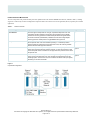
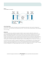
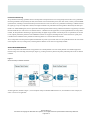
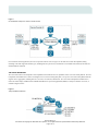
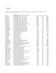
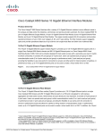
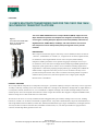
DATA SHEET
2.5-GBPS MULTIRATE TRANSPONDER CARD FOR THE CISCO ONS 15454
MULTISERVICE TRANSPORT PLATFORM
®
The Cisco ONS 15454 Multiservice Transport Platform (MSTP) support for a 2.5Gbps multirate transponder card simplifies the integration and transport of many
Figure 1
Cisco ONS 15454 SONET/SDH
MSTP 2.5-Gbps Multirate
Transponder Cards
service types, including Enterprise Systems Connection (ESCON), Fibre Channel,
Gigabit Ethernet, SONET/SDH (to 2.5 Gbps), and video interfaces and services
into enterprise as well as metropolitan (metro) and regional service provider
networks.
BACKGROUND
Metro transport networks must support a wide variety of service demands, from low-rate DS-1/E1, DS-3/E-3, 10/100BASE-T, OC-3/STM-1, etc., to higher-rate OC-12/STM-4, Gigabit Ethernet,
OC-48/STM-16, and 10 Gigabit Ethernet services. In the recent past, SONET add/drop
multiplexers (ADMs) provided the services platform to aggregate and transport services up to
OC-48/STM-16, where metro dense wavelength-division multiplexing (DWDM) platforms were
designed for optical signals from OC-3/STM-1 to OC-192/STM-64, including Gigabit and 10
Gigabit Ethernet. Unfortunately, deploying multiple platform types, including metro DWDM and
SONET ADMs, to support the wide variety of services is not cost effective for many service
provider and enterprise networks. Thus, a more cost-effective networking solution is required to
enable the delivery of all services, from lower-speed DS-1/E-1s to higher-speed 10 Gigabit
Ethernet and OC-192/STM-64s.
PRODUCT OVERVIEW
The 2.5-Gbps multirate transponder (2.5G transponder) card (Figure 1) provides the capability to transport a wide variety of service types from
155 Mbps to 2.48 Gbps, including services such as ESCON, SONET OC-3 through OC-48, SDH STM-1 through STM-16, Gigabit Ethernet, 1or 2-Gbps Fibre Channel, and other services, over a 100-GHz, ITU-compliant wavelength, with 50-GHz wavelength stability for future 64channel operation. The 2.5G transponder card architecture contains a single client interface that is mapped to a single-line DWDM interface,
without accessing the Cisco ONS 15454 shelf cross-connect fabric.
The interface to the client is via a variety of Small Form-Factor Pluggable (SFP) optics modules, enabling a wide service mix, including
ESCON, OC-3/STM-1, OC-12/STM-4, OC-48/STM-16, Gigabit Ethernet, 1-Gbps Fibre Channel/FICON, 2-Gbps Fibre Channel/FICON, as
well as high-definition television (HDTV), D1/SDI video, DV6000, and different fiber types (single- and multimode), wavelengths (850 and
1310 nm), and fiber reach (short reach/intra-office, intermediate reach/short haul, etc.). The SFP optics modules are equipped with LC
connectors to enable high-density placement on the card.
Cisco Systems, Inc.
All contents are Copyright © 1992–2004 Cisco Systems, Inc. All rights reserved. Important Notices and Privacy Statement.
Page 1 of 14
The DWDM line interface provides one long-reach/long-haul (LR/LH), ITU-compliant, 100-GHz spaced optical interface, with a 50-GHz
wavelength stability, using LC connectors; it operates at line rates of up to OC-48 plus G.709 overhead. The DWDM output line interface is
tunable across four adjacent 100GHz wavelengths, enabling support for 32-channel DWDM networks using eight discrete card types. Each 2.5G
transponder card wavelength is offered in protected or unprotected versions, with the protected version including a second DWDM line
output/input, enabling optical line protection over a DWDM network. Taking advantage of amplification and dispersion compensation, the 2.5G
transponder card is capable of optical reaches exceeding 500 km. When operated within the outlined specifications with forward error correction
enabled, the card delivers the client payload with a bite error rate (BER) up to 10E-15 (refer to Table 1).
The 2.5G transponder card incorporates both client and DWDM line interfaces on the same card. The 2.5G transponder cards are deployable in
the 12 multiservice interface card slots of the Cisco ONS 15454 platform, in systems with or without cross-connect cards. The only common
card type required for operation is the timing, communications, and control card in MSTP system deployments. The addition of a cross-connect
card to the Cisco ONS 15454 system, beginning with Release 4.6 software, enables support of hybrid applications, further enabling a mixture of
transparent 200-Mbps to 2.5-Gbps services as well as aggregated services via the cross-connect card to other transport cards.
The 2.5G transponder card supports many carrier-class features and advanced capabilities necessary to deliver the wide service mix, including
provisionable protocol transparency, wavelength tunability, flexible protection mechanisms, flow-through timing, management, and
performance-monitoring capabilities outlined in the following sections.
Provisionable Protocol Transparency
The 2.5G transponder card is designed to support both transparent wavelength and nontransparent services on the Cisco ONS 15454 platform
via three operating modes, 2R, 3R, and 3R+. In 2R mode, the 2.5G card passes data transparently between the client interface and the DWDM
line interfaces, and conversely. The data may vary at bit rates for 155 Mbps to 2.5 Gbps, and includes ESCON and video signals (HDTV, D1,
and C-Cor DV6000). The 2R mode regenerates and reamplifies the inbound signal, but does not provide retiming.
The 2.5G transponder card in 3R mode provides inbound signal regeneration, reamplification, and retiming. The data bit rates supported are
from 155 Mbps to 2.488 Gbps and include SONET/SDH OC-3/STM-1, OC-12/STM-4, and OC-48/STM-16 signals, 1- and 2-Gbps Fibre
Channel and FICON, and Gigabit Ethernet.
The 2.5 transponder card in 3R enhanced mode maps the client signal over G.709 with integrated forward error correction (FEC) for transparent
service support for the 3R signals outlined earlier. The G.709 technology provides an envelope the payload and provides a SONET/SDH-like
layering structure that provides in-service performance monitoring, protection, and optical management functions. This 3R+ mode improves
network performance and ultimately the reach of the system.
For SONET- or SDH-based client payloads, there are three operating modes, transparent (monitor only), line termination, and section
termination. When provisioned in transparent operating mode, the card passes all the SONET/SDH overhead bytes transparently. The card
monitors key SONET/SDH overhead bytes, such as B1 (section BIP-8) and J0 (section trace), to allow fault-isolation as well as performancemonitoring capabilities. Additionally, in transparent mode, in order to ensure network integrity, a client interface loss of signal or loss of frame
on one end of the network is transferred to the associated far-end client interface, shutting off the far-end laser. In line termination mode, the
client transport overhead (TOH) is terminated and the B1/B2 bytes are regenerated with appropriate remote indication signals inserted.
Wavelength Tunability
The 2.5G transponder cards operate on the 100-GHz ITU grid and are tunable across four adjacent 100-GHz channels per card, with 50-GHz
wavelength stability, allowing eight discrete cards to cover the entire 32-wavelength plan. The incorporation of tunability into the 2.5G
transponder cards greatly reduces the customer’s inventory to cover all the wavelengths for sparing needs.
Cisco Systems, Inc.
All contents are Copyright © 1992–2004 Cisco Systems, Inc. All rights reserved. Important Notices and Privacy Statement.
Page 2 of 14
Flexible Protection Mechanisms
The 2.5G transponder card provides flexible protection capabilities for both client and DWDM line interfaces, outlined in Table 1, enabling
support for a wide variety of network configurations required to deliver the various service-level agreements (SLAs) required by the customer
application.
Table 1.
Protection Formats
Protection Type
Capabilities
Figure
Unprotected client and DWDM
line interfaces
These interfaces provide no client terminal interface or transponder card protection.
The client signal is transported over a single, unprotected transponder card. This
configuration would be suitable for transporting client payloads over the DWDM
network that are being protected via unidirectional-path switched ring/Subnetwork
Connection Protection (UPSR/SNCP) or Bidirectional Line Switch Ring/multiplex
switching protection-shared protection ring(BLSR/MSP-SPR) protocols.
Figure 2
1+1 protected client interfaces
These interfaces provide protection for both the client terminal interfaces as well as
the transponder cards. Two client interfaces operating 1+1 automatic protection
switching (APS) are passed through two transponder cards, with switching handled
between client terminal equipment interfaces.
Figure 3
Y-cable client interface
This interface provides transponder equipment and DWDM transport protection
without client terminal equipment interface protection. A single client interface is split
to two transponder cards. This feature is not supported on the protected version of the
transponder card.
Figure 4
Protected DWDM line interface
This interface provides network protection for a single client signal using the protected
version of the 2.5G transponder card. This card splits the outbound signal into two
wavelength paths. At the receiver end, the card selects the better of two input signals,
forwarding it to the client transmitter.
Figure 5
Figure 2
Unprotected Configuration
Cisco Systems, Inc.
All contents are Copyright © 1992–2004 Cisco Systems, Inc. All rights reserved. Important Notices and Privacy Statement.
Page 3 of 14
Figure 3
1+1 Configurations
Figure 4
Y-Protection Configuration
Cisco Systems, Inc.
All contents are Copyright © 1992–2004 Cisco Systems, Inc. All rights reserved. Important Notices and Privacy Statement.
Page 4 of 14
Figure 5
Protected DWDM Line Configuration
Flow-Through Timing
The transponder card allows timing to “flow through” from client to DWDM line optical interfaces. Recovered receiver timing from one
interface (client or line) is used to time the other transmitter interface (line or client). This enables the transported signal to remain independent
from the node timing.
Management
The Cisco ONS 15454 provides comprehensive management capabilities to support the operations, administration, monitoring, and
provisioning (OAM&P) capabilities through the integrated Cisco Transport Controller craft interface with support from the Cisco Transport
Manager element management system (EMS). The 2.5G transponder card incorporates provisionable G.709 functions for all 3R service
interfaces. G.709 functionality enables a carrier transporting a service transparently to identify network impairments that may degrade the
transported signal and exceed SLA requirements. The general communication channel (GCC) of the G.709 provides a separate communications
channel on a per-wavelength basis for the transparently transported service channels, as compared with the section data communication
channel/regenerator section data communications channel (SDCC/RSDCC) in SONET/SDH signals. This GCC enables the Cisco ONS 15454
to extend its advanced network autodiscovery capabilities to DWDM-based services. For SONET/SDH services, when termination mode is
used, SDCC can be used to enable similar function on the Cisco ONS 15454 SONET/SDH network element, allowing the capabilities to
manage both SONET/SDH and DWDM networks at the same time. The integrated Cisco ONS 15454 Cisco Transport Controller craft manager
as well as the complementary Cisco Transport Manager EMS provide the user access for OAM&P for the system.
Cisco Systems, Inc.
All contents are Copyright © 1992–2004 Cisco Systems, Inc. All rights reserved. Important Notices and Privacy Statement.
Page 5 of 14
Performance Monitoring
The performance-monitoring capabilities of the 2.5G transponder card depend on the service being transported. For 2R services, performance
monitoring is limited to that provided by the SFP, which includes received and transmit powers, laser bias current, inventory, and the DWDM
optical interface, including received and transmit powers and laser bias current. For 3R services, performance monitoring is available based on
the signal type, except for 2-Gbps Fibre Channel, which again is limited to the performance-monitoring statistics delivered by the SFP optics
module. For SONET/SDH signals, extensive performance-monitoring and threshold-crossing conditions and alarms are supported per Telcordia
GR-474 and GR-2918, as well as ITU G.783 and ETS 300 417-1 standards. For data applications, such as Gigabit Ethernet and 1-Gbps Fibre
Channel, 8b/10b performance monitoring is supported. Finally, the digital wrapper channel is monitored per ITU-T requirements (G.709 and
G.798). Optical performance parameters on the DWDM line interface are supported, including laser bias current and receiver optical power.
Calculation and accumulation of the performance-monitoring data are in 15-minute and 24-hour intervals.
The 2.5 transponder cards incorporate faceplate-mounted LEDs to provide a quick visual check as to the operational status at the card. Printed
on the faceplate is an icon, an orange circle, indicating that the shelf slots on the card can be physically installed.
APPLICATION DESCRIPTION
The 2.5G transponder card adds numerous new applications to an already flexible Cisco ONS 15454 platform. One identified application
includes storage area networking (SAN) transport (Figure 6), providing connectivity between the primary and backup data centers for disaster
avoidance.
Figure 6
SAN Connectivity for Disaster Avoidance
Another application, detailed in Figure 7, is the transparent transport of SONET/SDH-based services, OC-48/STM-16 in this example, for a
carrier’s carrier service application.
Cisco Systems, Inc.
All contents are Copyright © 1992–2004 Cisco Systems, Inc. All rights reserved. Important Notices and Privacy Statement.
Page 6 of 14
Figure 7
OC-192/STM-64 Transport for Carrier’s Carrier Services
In each of these network applications, the user can provide a mixture of service types over the same Cisco ONS 15454 platform, taking
advantage of the other supported interface types, including DS-n/E-n private line, D1/SDI and C-Cor DV6000 video, Ethernet, ESCON, and
SONET/SDH OC-n/STM-m.
THE CISCO ADVANTAGE
The Cisco ONS 15454 2.5G Transponder Card complements and extends the services capabilities of the Cisco ONS 15454 platform. The 2.5G
transponder card enables users to deliver wavelength services over their existing fiber plant over a proven Cisco ONS 15454 platform that also
supports service aggregation, including DS-1/E-1, DS-3/E-3, OC-n/STM-n, and Ethernet. The Cisco ONS 15454 platform enables users to
reduce the need to deploy standalone metro DWDM and multiservice provisioning platforms (MSPPs) to transport a mixture of services, as
outlined in Figures 8 and 9.
Figure 8
Today’s DWDM Architectures
Cisco Systems, Inc.
All contents are Copyright © 1992–2004 Cisco Systems, Inc. All rights reserved. Important Notices and Privacy Statement.
Page 7 of 14
Figure 9
Cisco ONS 15454 Hybrid DWDM Architecture
The Cisco ONS 15454 Optical Transport solution offers significant advantages over traditional network elements that offer broad deployment
and capabilities, including:
• Unprecedented service interface selection—The Cisco ONS 15454 platform supports the broadest range of service interfaces available on a
single chassis type by using software personality loads, including asynchronous (DS-1/E-1, DS-3/E-3), SONET/SDH (EC-1, OC-3/STM-1 to
OC-192/STM-64), Ethernet (10, 100, 1000, and 10,000 Mbps), SAN (ESCON, FICON, 1- and 2-Gbps Fibre Channel), and video (D1 and CCor DV6000) interfaces.
•
Multiple restoration types—The Cisco ONS 15454 MSPP platform supports two- or four-fiber BLSR/MS-SPR, UPSR/SNCP, linear
APS/SNC, and path-protected mesh networking (PPMN). This allows the service provider to deploy the platform in all areas of the transport
networking applications, including the inter-office network, normally deployed using two- or four-fiber BLSR/MS-SPR restoration, as well
as the collector or fiber to the building networks, normally taking advantage of UPSR/SNCP restoration.
•
Common line cards and chassis—Optical line cards are not restoration-type dependent, reducing sparing costs and technician confusion.
Additionally, as networks change and customer interface demands evolve, the user has the ability to easily and simply redeploy optical
circuit packs as necessary.
•
Common chassis type—A common chassis supporting all optical interface speeds allows the technician to spend time deploying bandwidth
and services instead of learning about multiple equipment platforms. Many equipment vendors offer optical-line-speed-specific platforms
(OC-3/STM-1, OC-12/STM-4, and so on) and categorize platforms by restoration mechanisms (UPSR/SNCP, 2F-BLSR/MS-SPR, 4FBLSR/MS-SPR, etc.). This not only causes confusion when ordering, but also may bring into question whether the required platform will be
available to support the desired application. The line rate and restoration flexibility of the Cisco ONS 15454 makes ordering and deploying
simple, fast, and easy.
The Cisco ONS 15454, the industry’s leading metro optical transport platform, delivers supercharged SONET/SDH transport, integrated optical
networking, unprecedented multiservice interfaces, and competitive economic benefits.
Cisco Systems, Inc.
All contents are Copyright © 1992–2004 Cisco Systems, Inc. All rights reserved. Important Notices and Privacy Statement.
Page 8 of 14
CISCO ONS 15454 2.5-GBPS MULTIRATE TRANSPONDER CARD FEATURES AND SPECIFICATIONS
Compact Design
• High-density solution with single chassis slot design supporting bidirectional client to DWDM operation
• Up to 12 bidirectional 2.5G transponder cards per shelf assembly, 48 cards per bay
Flexible Protection Options
• Transparent support for UPSR/SNCP, BLSR/MSP, and 1+1 APS/SNC
• Y-cable client
• Protected DWDM line option
• Unprotected (0+1)
Regulatory Compliance
Table 2.
1
Regulatory Compliance
Countries Supported
SONET/ANSI System
SDH/ETSI System2
• Canada
• EU
• United States
• Australia
• Mexico
• New Zealand
• Korea
• Singapore
• Japan
• China
• EU
• Mexico
• Hong Kong
• Korea
EMC Emissions (radiated, conducted)
• ICES-003
• EN 300 386-TC
• GR-1089-CORE
• EN50081-1
• 47CFR15
• EN55022
• VCCI V-3/2000.04
• AS/NZS3548, Amendment 1 + 2 1995
• CISPR22
EMC Immunity
• GR-1089-CORE
• EN300-386-TC
• CISPR24
• EN55024
• EN50082-2
Cisco Systems, Inc.
All contents are Copyright © 1992–2004 Cisco Systems, Inc. All rights reserved. Important Notices and Privacy Statement.
Page 9 of 14
Safety
• CAN/CSA-C22.2 No. 60950-00 Third Ed., 12/1/2002
• UL 1950 Third Ed., 12/1/2000
• GR-1089-CORE
• EN60950 (to A4)
• GR-63-CORE
• IEC60950/EN60950, Third Ed.
• TS001
• AS/NZS3260 Supplements 1,2,3,4, 1997
Environmental
• GR-63-CORE
• ETS 300-019-2-1 (Class 1.1)
• AT&T Network Equipment Design Specification (NEDS)
• ETS 300-019-2-2 (Class 2.3)
• ETS 300-019-2-3 (Class 3.1E)
Structural Dynamics
• GR-63-CORE
• ETS 300-019 (Class 3.1E)
• AT&T NEDS
Power and Grounding
• SBC (TP76200MP)
• ETS 300-253 (grounding)
• ETS 300-132-1 (DC power)
Optical
• GR-253-CORE
• G.709
• G.691
• G.975
Quality
• TR-NWT-000332, Issue 4, Method 1 calculation for 20-year mean time between failure (MTBF)
1. All compliance testing and documentation may not be completed at release of the product. Check with your sales representative for countries outside of Canada, the
United States, and the European Union.
2. For other countries with SDH/ETSI requirements, confirm compliance with a Cisco account representative.
Table 3.
System Requirements
Component
Cisco ONS 15454 SONET/ANSI
Cisco ONS 15454 SDH/ETSI
Processor
TCC2 and TCC2P
TCC2 and TCC2P
Cross-connect
All (not required)
All (not required)
Shelf assembly
15454-SA-ANSI or 15454-SA-HD shelf assembly
with FTA3 version fan-tray assembly
15454-SA-ETSI shelf assembly with SDH 48V
fan-tray assembly
System software
Release 4.6.0 or greater
Release 4.6.0 or greater
Slot compatibility
1–6, 12–17
1–6, 12–17
Cisco Systems, Inc.
All contents are Copyright © 1992–2004 Cisco Systems, Inc. All rights reserved. Important Notices and Privacy Statement.
Page 10 of 14
Table 4.
Specifications
Specification
Client Interfaces
Input bit rate
155 Mbps to 2.5 Gbps
Supported interfaces (Small Form-Factor Pluggable [SFP] based)
SONET/SDH
OC-3/STM-1
1310 nm, single-mode fiber (SMF), 15 km IR-1/S-1.1
OC-12/STM-4
1310 nm, SMF, 15 km IR-1/S-4.1
OC-48/STM-16
1310 nm, SMF, 15 km IR-1/S-16.1
1310 nm, SMF, 2 km SR-1/I-16.1
Gigabit Ethernet
850 nm, multimode fiber (MMF), 0.5 km, 1000BASE-SX
1310 nm, SMF, 10 km, 1000BASE-LX
Fibre Channel/FICON, 1 Gbps and 2 Gbps
850 nm, MMF, 0.3 km
1310 nm, SMF, 10 km
ESCON
1310 nm, MMF, 2 km
Video
D1 video
1310 nm, SMF
C-Cor DV6000 2.5 Gbps
1310 nm, SMF
HDTV
1310 nm, SMF
Automatic laser shutdown (ALS) and restart
ITU-T G.664 (06/99)
Connector type (Tx/Rx)
LC, duplex
DWDM Line Interface
Output bit rate
155 Mbps to 2.66 Gbps
ALS and restart
ITU-T G.664 (06/99)
Wavelength, nominal, (λTnom)
Four-channel tunable (Table 5)
Spectral range (λTmin to λTmax)
1530 to 1565 nm
Spectral width @ 20 dB (∆λ20)
+/–0.025 nm
Connector type (Tx/Rx)
LC, duplex
Optical Transmitter
Type
Direct modulated
Output power (PTmin to PTmax)
Unprotected card
–1 to +1 dBm
Protected card
–4.5 to –2.5 dBm
Required optical return loss, minimum
20 dB
Extinction ratio, minimum (reminx)
8.2 dBm
Laser safety class
1
Cisco Systems, Inc.
All contents are Copyright © 1992–2004 Cisco Systems, Inc. All rights reserved. Important Notices and Privacy Statement.
Page 11 of 14
Specification
Optical Receiver
Type
APD
Sensitivity, 3R mode (PRmin to PRmax)
FEC off; BER = 10E-12; OSNR >14 dB
–28 to –9 dBm
FEC on; BER = 10E-15; OSNR >14 dB
–31 to –9 dBm
FEC off; BER = 10E-12; OSNR >11 dB
–23 to –9 dBm
FEC on; BER = 10E-15; OSNR >7 dB
–23 to –9 dBm
Sensitivity, 2R mode (PRmin to PRmax)
–24 to –9 dBm
BER = 10E-12; OSNR >15 dB
Note: Optical signal to noise ration (OSNR) defined at 0.5-nm bandwidth
Transmission penalties
3R mode—Dispersion power penalty (FEC on or off)
2 dB @ +/–5400 ps
3R mode—Dispersion OSNR penalty (FEC on or off)
2 dB @ +/–5400 ps
3
2R mode—Dispersion power penalty
3 dB @ +/–3300 ps
Chromatic dispersion tolerance (DLRmax)
Up to +/–5400 ps/nm (360 km in 3R mode)
Receiver reflectance (maximum)
–27 dB
Input wavelength bandwidth (λc_rx)
Third window, ITU G.692,
1530–1565 nm
Management
Card LEDs
Failure (FAIL)
Red
Active/standby (ACT/STBY)
Green/yellow (Y-protection)
Signal fail (SF)
Yellow
Client port LEDS (bicolor)
Active-no alarms/alarm
Green/red
DWDM port LEDs (tricolor)
Active/standby (protection card only)/alarm
Green/yellow/red
Power
Typical
25 watts
Maximum
35 watts
Operating environment
Temperature
–5 to 55°C
23 to 131°F
Humidity
5 to 95% noncondensing
Storage environment
Temperature
–40 to 185°F
40 to 85°C
Humidity
5 to 95% noncondensing
3. Reach in 2R mode is OSRN limited as compared with dispersion limited.
Cisco Systems, Inc.
All contents are Copyright © 1992–2004 Cisco Systems, Inc. All rights reserved. Important Notices and Privacy Statement.
Page 12 of 14
Table 5.
Supported Wavelengths on 2.5-Gbps Multirate Transponder Cards4
Card (xx.x)
λ (nm)
Card (xx.x)
λ (nm)
Card (xx.x)
λ (nm)
Card (xx.x)
λ (nm)
30.3
1530.33
38.1
1538.19
46.1
1546.12
54.1
1554.13
34.2
1531.12
1538.98
1546.92
1554.94
1531.90
1539.77
1547.72
1555.75
1532.68
1540.56
1548.51
1556.55
42.1
1534.25
1542.14
50.1
1550.12
58.1
1558.17
1535.04
1542.94
1550.92
1558.98
1535.82
1543.73
1551.72
1559.79
1536.61
1544.53
1552.52
1560.61
4. Lead times on wavelength-based optical modules vary substantially. For assistance with wavelength selection, refer to Cisco price list or lead-time tool, available on
Cisco ordering page at the following URL: http://www.cisco.com/en/US/ordering/index.shtml
Table 6.
Ordering Information5
Part Number
Description
15454-MR-L1-xx.x=
100-Mbps to 2.5-Gbps multirate transponder card, unprotected DWDM line, SFP client module slot, 100-GHz
ITU DWDM wavelength, LC connectors
15454E-MR-1-xx.x=
15454-MRP-L1-xx.x=
15454E-MRP-1-xx.x=
100-Mbps to 2.5-Gbps multirate transponder card, protected DWDM line, SFP client module slot, 100-GHz
ITU DWDM wavelength, LC connectors
SFP Optics Modules
15454-SFP3-1-IR=
OC-3/STM-1/D1-SDI SFP, intermediate reach, 1310 nm, single mode, LC connector
15454E-SFP3-1-IR=
15454-SFP12-4-IR=
OC-12/STM-4 SFP, intermediate reach, 1310 nm, single mode, LC connector
15454E-SFP12-4-IR=
15454-SFP-OC48-IR=
OC-48/STM-16 SFP, intermediate reach, 1550 nm, single mode, LC connector
15454E-SFP-OC48-IR=
ONS-SE-2G-S1=
OC-48/STM-16 SFP optics module, short-reach/intra-office, 1310-nm, single-mode, LC connectors
15454-SFP-200=
ESCON SFP, short reach, 1310 nm, multimode, LC connector
15454E-SFP-200=
15454-SFP-GE+-LX=
15454E-SFP-GE+-LX=
15454-SFP-GEFC-SX=
Gigabit Ethernet, Fibre Channel/FICON (1 and 2 Gbps) and HDTV SFP, long reach, 1310 nm, single mode, LC
connector
Gigabit Ethernet and Fibre Channel/FICON (1 and 2 Gbps) SFP, short reach, 850 nm, multimode, LC connector
15454E-SFP-GEFC-SX=
Y-Protection Devices
15216-CS-SM-Y=
Y-cable splitter/combiner module, single mode, single-width module, installs in Cisco FlexLayer shelf assembly
(15216-FL-SA)
15216-CS-MM-Y=
Y-cable splitter/combiner module, multimode, single-width module, installs in Cisco FlexLayer shelf assembly
(15216-FL-SA)
15216-FL-SA=
Shelf assembly, 4 module slots, 1 rack unit high, Cisco FlexLayer platform
5. The “E” (that is, 15454E) in the part numbers indicates SDH system compatibility.
Cisco Systems, Inc.
All contents are Copyright © 1992–2004 Cisco Systems, Inc. All rights reserved. Important Notices and Privacy Statement.
Page 13 of 14
Corporate Headquarters
Cisco Systems, Inc.
170 West Tasman Drive
San Jose, CA 95134-1706
USA
www.cisco.com
Tel: 408 526-4000
800 553-NETS (6387)
Fax: 408 526-4100
European Headquarters
Cisco Systems International BV
Haarlerbergpark
Haarlerbergweg 13-19
1101 CH Amsterdam
The Netherlands
www-europe.cisco.com
Tel: 31 0 20 357 1000
Fax: 31 0 20 357 1100
Americas Headquarters
Cisco Systems, Inc.
170 West Tasman Drive
San Jose, CA 95134-1706
USA
www.cisco.com
Tel: 408 526-7660
Fax: 408 527-0883
Asia Pacific Headquarters
Cisco Systems, Inc.
168 Robinson Road
#28-01 Capital Tower
Singapore 068912
www.cisco.com
Tel: +65 6317 7777
Fax: +65 6317 7799
Cisco Systems has more than 200 offices in the following countries and regions. Addresses, phone numbers, and fax numbers are listed on
the Cisco Website at www.cisco.com/go/offices.
Argentina • Australia • Austria • Belgium • Brazil • Bulgaria • Canada • Chile • China PRC • Colombia • Costa Rica
Croatia • Cyprus • Czech Republic • Denmark • Dubai, UAE • Finland • France • Germany • Greece • Hong Kong SAR
Hungary • India • Indonesia • Ireland • Israel • Italy • Japan • Korea • Luxembourg • Malaysia • Mexico
The Netherlands • New Zealand • Norway • Peru • Philippines • Poland • Portugal • Puerto Rico • Romania • Russia
Saudi Arabia • Scotland • Singapore • Slovakia • Slovenia • South Africa • Spain • Sweden • Switzerland • Taiwan
Thailand • Turkey • Ukraine • United Kingdom • United States • Venezuela • Vietnam • Zimbabwe
Copyright 2004 Cisco Systems, Inc. All rights reserved. Cisco, Cisco Systems, and the Cisco Systems logo are registered trademarks or trademarks of Cisco Systems, Inc.
and/or its affiliates in the United States and certain other countries.
Inc. The use of the word partner does not imply a partnership relationship
All other trademarks mentioned in this document or Website are the propertyCisco
of theirSystems,
respective owners.
Alland
contents
Copyright
© 1992–2004 Cisco Systems, Inc. All rights reserved. Important Notices and Privacy Statement.
between Cisco
any otherare
company.
(0406R)
Hu/LW6602 09/04
Page 14 of 14
Printed in USA