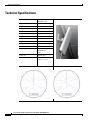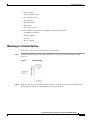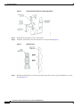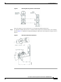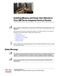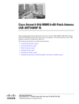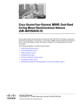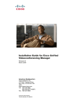
1
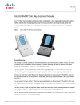
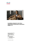
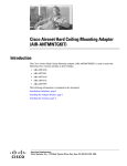
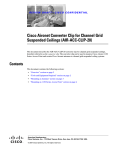
Cisco Aironet 5-dBi Diversity Omnidirectional
Antenna (AIR-ANT2452V-R)
This document outlines the specifications for the Cisco Aironet 5-dBi Diversity Omnidirectional
Antenna (AIR-ANT2452V-R) and provides instructions for mounting it. The antenna operates in the 2.4
GHz frequency range and is designed for indoor use.
The following information is provided in this document.
•
Technical Specifications, page 2
•
System Requirements, page 3
•
Safety Precautions, page 3
•
Installation Notes, page 4
•
Installing the Antenna, page 4
•
Obtaining Documentation, Obtaining Support, and Security Guidelines, page 9
Americas Headquarters:
Cisco Systems, Inc., 170 West Tasman Drive, San Jose, CA 95134-1706 USA
© 2009 Cisco Systems, Inc. All rights reserved.
Technical Specifications
Technical Specifications
Antenna type
Diversity
Omnidirectional
Operating frequency range
2400 MHz - 2500 MHz
VSWR
< 2:1
Gain
5 dBi
Polarization
Linear, Vertical
Elevation Plane Beamwidth 27 degrees
Azimuth Plane Beamwidth 360 degrees
Length
11 in. (27.24 cm)
Width
5 in. (12.7 cm)
Depth
1 in. (2.54 cm)
Environment
Indoor
Cable length and type
Conjoined
Plenum Rated
36 in.
Connector
RP-TNC plug
Operating temperature
-22 to 167 F
(-30 C to +75 C)
Azimuth and Elevation Radiation Patterns
Azimuth and Elevation Radiation Patterns
Cisco Aironet 5-dBi Diversity Omnidirectional Antenna (AIR-ANT2452V-R)
2
78-19009-01
System Requirements
System Requirements
This antenna is designed for indoor use with any 2.4-GHz Cisco Aironet radio device that uses a RP-TNC
connector.
Safety Precautions
Translated versions of the following safety warnings are provided in the Safety Warnings for Cisco
Aironet Antennas, which is available at http://cisco.com.
Warning
Installation of this antenna near power lines is dangerous. For your safety, follow the installation
directions.
Each year hundreds of people are killed or injured when attempting to install an antenna. In many of
these cases, the victim was aware of the danger of electrocution but did not take adequate steps to avoid
the hazard.
For your safety, and to help you achieve a good installation, please read and follow these safety
precautions. They may save your life!
1.
If you are installing an antenna for the first time, for your own safety as well as others, seek
professional assistance. Your Cisco sales representative can explain which mounting method to use
for the size and type antenna you are about to install.
2.
Select your installation site with safety as well as performance in mind. Remember: electric power
lines and phone lines look alike. For your safety, assume that any overhead line can kill you.
3.
Call your electric power company. Tell them your plans and ask them to come look at your proposed
installation. This is a small inconvenience considering your life is at stake.
4.
Plan your installation carefully and completely before you begin. Successful raising of a mast or
tower is largely a matter of coordination. Each person should be assigned a specific task, and should
know what to do and when to do it. One person should be in charge of the operation to issue
instructions and watch for signs of trouble.
5.
When installing your antenna, remember:
a. Do not use a metal ladder.
b. Do not work on a wet or windy day.
c. Do dress properly—shoes with rubber soles and heels, rubber gloves, long sleeved shirt or
jacket.
6.
If the assembly starts to drop, get away from it and let it fall. Remember, the antenna, mast, cable,
and metal guy wires are all excellent conductors of electrical current. Even the slightest touch of any
of these parts to a power line completes an electrical path through the antenna and the installer: You!
7.
If any part of the antenna system should come in contact with a power line, don’t touch it or try to
remove it yourself. Call your local power company. They will remove it safely.
8.
If an accident occurs with the power lines, call for qualified emergency help immediately.
Cisco Aironet 5-dBi Diversity Omnidirectional Antenna (AIR-ANT2452V-R)
78-19009-01
3
Installation Notes
Installation Notes
Antennas transmit and receive radio signals which are susceptible to RF obstructions and common
sources of interference that can reduce throughput and range of the device to which they are connected.
Follow these guidelines to ensure the best possible performance:
•
Install the antenna vertically and mount it as high as possible.
•
Keep the antenna away from metal obstructions such as heating and air-conditioning ducts, large
ceiling trusses, building superstructures, and major power cabling runs. If necessary, use a rigid
conduit to lower the antenna away from these obstructions.
•
The density of the materials used in a building’s construction determines the number of walls the
signal can pass through and still maintain adequate signal strength. Consider the following before
choosing the location for your antenna:
– Signals penetrate paper and vinyl walls with little change to signal strength.
– Signals penetrate only one or two solid and pre-cast concrete walls without degrading signal
strength.
– Signals penetrate three or four concrete and wood block walls without degrading signal
strength.
– Signals penetrate five or six walls constructed of drywall or wood without degrading signal
strength.
– Signals will likely reflect off a thick metal wall and may not penetrate it at all.
– Signals will likely reflect off a chain link fence or wire mesh spaced between 1 and 1 1/2 in.
(2.5 and 3.8 cm). The fence acts as a harmonic reflector that blocks the signal.
•
Install the antenna away from microwave ovens and 2-GHz cordless phones. These products can
cause signal interference because they operate in the same frequency range as the device to which
your antenna is connected.
Choosing a Mounting Location
The antenna should be mounted clear of any obstructions to the sides of the radiating elements.
Generally, the higher an antenna is above the floor, the better it performs. If possible, find a mounting
place directly above your wireless device to ensure the lead-in cable can be as short as possible.
Installing the Antenna
You can install the antenna on any flat vertical surface or on a pole. All hardware for mounting the
antenna on a wall is provided. If you intend to install your antenna on another surface, you must provide
the appropriate hardware.
Tools and Equipment Required
A mounting installation kit is included with the antenna and consists of the following hardware:
•
Antenna bracket
•
One 1/4 –20 cap screw
Cisco Aironet 5-dBi Diversity Omnidirectional Antenna (AIR-ANT2452V-R)
4
78-19009-01
Installing the Antenna
•
One flat washer
•
One screen mesh washer
•
One spherical washer
•
One wing bolt
•
Mounting bracket
•
Wall bracket
•
Four #8 x ¾ in. screws
You may need the following tools and equipment, which are not provided.
•
A #2 Phillips screwdriver
•
A drill and drill bit
•
A pencil
•
Two hose clamps
Mounting on a Vertical Surface
Follow these steps to mount your antenna on a vertical surface.
Step 1
Attach the antenna bracket to the antenna using the 1/4 – 20 cap screw and flat washer provided
(Figure 1).
Figure 1
Step 2
Antenna Bracket
With the screen mesh washer between the two brackets, attach the antenna bracket to the mounting
bracket using the spherical washer and wing bolt provided (Figure 2).
Cisco Aironet 5-dBi Diversity Omnidirectional Antenna (AIR-ANT2452V-R)
78-19009-01
5
Installing the Antenna
Figure 2
Antenna Bracket Attached to Mounting Bracket
Step 3
Determine the mounting location for the antenna.
Step 4
Attach the wall bracket to the wall using the two screws provided (Figure 3).
Figure 3
Step 5
Wall Mounting
Slide the mounting bracket onto the wall bracket and secure it in place (optional) with the two screws
provided (Figure 4).
Cisco Aironet 5-dBi Diversity Omnidirectional Antenna (AIR-ANT2452V-R)
6
78-19009-01
Installing the Antenna
Figure 4
Attaching Mounting Bracket to Wall Bracket
Once the antenna is secured on the wall, you can adjust the azimuth and elevation.
Step 6
To adjust the azimuth and elevation, loosen the bolt that attaches the antenna bracket to the mounting
bracket (Figure 5). Azimuth can be adjusted ±90 degrees. Elevation can be adjusted +15 degrees and -35
degrees.
Figure 5
Azimuth and Elevation Adjustment
Cisco Aironet 5-dBi Diversity Omnidirectional Antenna (AIR-ANT2452V-R)
78-19009-01
7
Installing the Antenna
Mounting on a Mast
The antenna can be mounted on a mast rather than on a wall using two 1/2 inch-wide hose clamps (not
provided).
To mount the antenna on a mast, follow these steps:
Step 1
Follow Step 1 and Step 2 from “Mounting on a Vertical Surface”.
Step 2
Position the antenna, mounting bracket, and hose clamps on the mast.
Step 3
Tighten the hose clamps until the antenna is secure on the mast.
Once the antenna is secured on the mast, you can adjust the azimuth and elevation.
Step 4
To adjust the azimuth and elevation, loosen the bolt that attaches the antenna bracket to the mounting
bracket (Figure 5). Azimuth can be adjusted ±90 degrees. Elevation can be adjusted +15 degrees and -35
degrees.
Suggested Cable
Cisco recommends a high-quality, low-loss cable for use with the antenna.
Note
Coaxial cable loses efficiency as the frequency increases, resulting in signal loss. The cable should be
kept as short as possible because cable length also determines the amount of signal loss (the longer the
run, the greater the loss).
Each antenna terminates with a RP-TNC plug after a short, 3-ft (0.91-m) cable. The mating connector
to the antenna is an appropriate RP-TNC jack. The connector on the opposite end will vary according to
the type of equipment used.
Cisco Aironet 5-dBi Diversity Omnidirectional Antenna (AIR-ANT2452V-R)
8
78-19009-01
Obtaining Documentation, Obtaining Support, and Security Guidelines
Obtaining Documentation, Obtaining Support, and Security
Guidelines
For information on obtaining documentation, obtaining support, providing documentation feedback,
security guidelines, and also recommended aliases and general Cisco documents, see the monthly
What’s New in Cisco Product Documentation, which also lists all new and revised Cisco technical
documentation, at:
http://www.cisco.com/en/US/docs/general/whatsnew/whatsnew.html
CCDE, CCENT, Cisco Eos, Cisco HealthPresence, the Cisco logo, Cisco Lumin, Cisco Nexus, Cisco StadiumVision, Cisco TelePresence,
Cisco WebEx, DCE, and Welcome to the Human Network are trademarks; Changing the Way We Work, Live, Play, and Learn and Cisco Store are
service marks; and Access Registrar, Aironet, AsyncOS, Bringing the Meeting To You, Catalyst, CCDA, CCDP, CCIE, CCIP, CCNA, CCNP, CCSP,
CCVP, Cisco, the Cisco Certified Internetwork Expert logo, Cisco IOS, Cisco Press, Cisco Systems, Cisco Systems Capital, the Cisco Systems logo,
Cisco Unity, Collaboration Without Limitation, EtherFast, EtherSwitch, Event Center, Fast Step, Follow Me Browsing, FormShare, GigaDrive,
HomeLink, Internet Quotient, IOS, iPhone, iQuick Study, IronPort, the IronPort logo, LightStream, Linksys, MediaTone, MeetingPlace,
MeetingPlace Chime Sound, MGX, Networkers, Networking Academy, Network Registrar, PCNow, PIX, PowerPanels, ProConnect, ScriptShare,
SenderBase, SMARTnet, Spectrum Expert, StackWise, The Fastest Way to Increase Your Internet Quotient, TransPath, WebEx, and the WebEx logo
are registered trademarks of Cisco Systems, Inc. and/or its affiliates in the United States and certain other countries.
All other trademarks mentioned in this document or website are the property of their respective owners. The use of the word partner does not imply
a partnership relationship between Cisco and any other company. (0812R)
Cisco Aironet 5-dBi Diversity Omnidirectional Antenna (AIR-ANT2452V-R)
78-19009-01
9