1
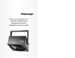
00-02408D_unit_7120_Cover_Oct_2005.qxd
10/26/2005
11:31 AM
Page 1
METROLOGIC INSTRUMENTS, INC.
MS7120 Orbit Presentation
Laser Scanner
Installation and User’s Guide
®
Copyright
© 2008 by Metrologic Instruments, Inc. All rights reserved. No part of this
work may be reproduced, transmitted, or stored in any form or by any means
without prior written consent, except by reviewer,
who may quote brief passages in a review, or provided for in the Copyright
Act of 1976.
Products and brand names mentioned in this document are trademarks of
their respective companies.
TABLE OF CONTENTS
Introduction................................................................................................1
Scanner and Accessories..........................................................................2
Operational Notes .....................................................................................3
Installation
For RS232, OCIA and IBM 46XX Interfaces.........................................4
For Keyboard Wedge Interface .............................................................5
For Stand Alone Keyboard Interface.....................................................6
Notes for USB Interface ........................................................................7
Notes for MS7120-00 'Laser Emulation' ...............................................7
Scanner Parts............................................................................................8
Audible Indicators......................................................................................9
Visual Indicators ......................................................................................10
Failure Modes..........................................................................................11
Labels......................................................................................................12
Maintenance............................................................................................12
Scan Volume Specifications
Optimal Low Density (Default) ............................................................13
Optimal High Density ..........................................................................13
Close ...................................................................................................14
Normal.................................................................................................14
Far.......................................................................................................15
Depth of Field by Minimum Bar Code Element Width
Optimal Low Density (Default) ............................................................16
Optimal High Density ..........................................................................17
Close ...................................................................................................18
Normal.................................................................................................19
Far.......................................................................................................20
ii
TABLE OF CONTENTS
Installing the Optional Wall/Counter Mount .............................................21
Troubleshooting Guide ............................................................................22
RS-232 Demonstration Program .............................................................27
Applications and Protocols ......................................................................28
Design Specifications ..............................................................................29
Default Settings .......................................................................................31
Scanner and Cable Terminations............................................................36
Limited Warranty .....................................................................................39
Notices ....................................................................................................40
Patents ....................................................................................................44
Index........................................................................................................45
iii
INTRODUCTION
Orbit® is an aggressive, omnidirectional laser bar code scanner.
Lightweight and rugged, Orbit is small in size, but BIG in performance.
Designed for applications where counter space is limited, Orbit is the
ideal presentation scanner for retail, convenience, liquor and specialty
stores. In addition, Orbit’s unique, contoured shape allows it to be
picked-up and used as a hand-held scanner when scanning large or
bulky items.
Engineered with a large, easy-to-find optimal scan area, Orbit increases
the first pass read rate for maximum productivity. The scanning head can
be tilted vertically a full 30° for added flexibility when scanning various
sized objects. These features increase the scanning throughput without
increasing the scanner size.
SCANNER
INTERFACE
7120-00
Laser Emulation, RS-232 Transmit/Receive
7120-9
OCIA and RS-232 Transmit/Receive (Full RS232 Configurable)
7120-11
IBM 46XX and Full RS-232C
7120-41
Full RS-232C/Light Pen Emulation
7120-47
Keyboard Wedge, Stand-Alone Keyboard and RS-232
Transmit/Receive
7120-62
Ruby with Verifone, RS232
7120-67
Full RS-232C (OCIA Configurable)
Orbit offers a great deal of features to the consumer:
•
•
•
•
•
•
Fully automatic scanning operation
PowerLink compatible
Data editing
7 beeper tones
Programmable depth of field
Easy programming
1
SCANNER AND ACCESSORIES
BASIC KIT
Part #
Description
®
MS7120
Orbit Presentation Laser Scanner
00-02407
MetroSelect Programming Guide
00-02408
MS7120 Installation and User’s Guide*
®
* Available on the Metrologic website - www.metrologic.com
OPTIONAL ACCESSORIES
Part #
Description
AC to DC Power Transformer- Regulated 5.2VDC @ 650 mA output.
45-45593
120V United States
45-45591
220V-240V Continental European
45-45592
220V-240V United Kingdom
46-46803
220V-240V Australia
46-46983
220V-240V China
54-54xxx
PowerLink Cable with built in power jack
Standard - 2.1m (7') straight cord, short strain relief
53-53xxx
PowerLink Cable with built in power jack
Optional - 2.7m (9') coiled cord, long strain relief
xxx specifies connection to the host.
54-54002
Keyboard Wedge PowerLink Cable with Adapter Cable
54-54020
Stand Alone Keyboard PowerLink Cable
Other items may be ordered for the specific protocol being used. To order additional items,
contact the dealer, distributor or call Metrologic’s Customer Service Department at
1-800-ID-METRO or 1-800-436-3876.
2
SCANNER AND ACCESSORIES
OPTIONAL ACCESSORIES
Part #
Description
MVC**
Metrologic Voltage Converter Cable
+12VDC to +5.2VDC or -12VDC to +5.2VDC
MX009-2**
MX009 USB Converter Cable
** Contact a Metrologic customer service representative for additional
information on the MVC and MX009 cable series and the host connections
available.
45-45619
Counter/Wall Mount Kit
Other items may be ordered for the specific protocol being used. To order
additional items, contact the dealer, distributor or call Metrologic’s Customer
Service Department at 1-800-ID-METRO or 1-800-436-3876.
OPERATIONAL NOTES
Metrologic recommends using the external power supply provided with the
scanner when operating the MS7120. When using power supplied by the host,
the host system should supply a minimum of 250 mA of current @ 5VDC.
Orbit is shipped from the factory programmed with default settings. To configure
the MS7120 scanner to meet the host system’s specific needs, refer to the
MetroSelect Programming Guide (MLPN 00-02407B) for instructions on how to
enter the program mode and select the appropriate bar codes.
3
INSTALLATION FOR RS232, OCIA AND IBM 46XX INTERFACES
1. Turn off the host system.
2. Plug the male 10-pin RJ45 end of
the PowerLink cable into the 10-pin
jack on the MS7120.
3. Connect the 9 pin female end of
the PowerLink cable to the host
device.
Note: Skip to #6 if receiving power
from the host system.
4. Plug the power supply’s L-shaped
plug into the power jack on the
PowerLink cable.
5. Check the AC input requirements
of the power supply to make sure
the voltage matches the AC outlet.
The outlet should be installed near
the equipment and be easily
accessible. Connect AC power to
the transformer.
6.
Turn on the host system.
Note:
a. When the scanner first receives power, the green LED will turn
on. Then the scanner will beep once and the red LED will flash
simultaneously.
b. Plugging the scanner into the serial port of the PC does not
guarantee that scanned information will appear at the PC. A
software driver and correct configuration setting are also required
for proper communication to occur.
Caution:
To maintain compliance with applicable standards, all circuits connected to the scanner must meet the
requirements for SELV (Safety Extra Low Voltage) according to EN 60950.
To maintain compliance with standard CSA C22.2 No. 950/UL 1950 and norm EN 60950, the power
source should meet applicable performance requirements for a limited power source.
4
INSTALLATION FOR KEYBOARD WEDGE INTERFACE
1. Turn off the PC/Host.
2. Connect the male 10-pin RJ45 end of
the PowerLink cable to the jack on
the MS7120.
3. Connect the L-shaped plug of the
power supply into the power jack on
the PowerLink cable.
4. Make sure the AC input requirements
of the power supply matches the AC
outlet. Plug the power supply into the
AC outlet. The outlet should be near
the equipment and easily accessible.
5. Disconnect the keyboard from the PC.
Note the type of connector on the
keyboard and keyboard port on the PC.
6. The “Y” end of the PowerLink cable
terminates to female 5-pin DIN and
a male 6-pin mini DIN connector. If
necessary attach the supplied
adapter cable to the appropriate
end of the “Y” cable.
7. Connect one end of the “Y” cable to the Keyboard and other end of
the “Y” to the Keyboard port on the PC.
8. Power up the PC.
Manufacturer’s Recommendation:
Powering Orbit directly from the computer can sometimes cause
interference with the operation of the scanner or the computer. Not all
computers supply the same current through the keyboard port, explaining
why a scanner will work on one computer and not another. Metrologic
recommends using an external power supply. For additional information
contact a Metrologic customer service representative.
Caution:
To maintain compliance with applicable standards, all circuits connected to the scanner must meet the
requirements for SELV (Safety Extra Low Voltage) according to EN 60950.
To maintain compliance with standard CSA C22.2 No. 950/UL 1950 and norm EN 60950, the power
source should meet applicable performance requirements for a limited power source.
5
INSTALLATION FOR STAND ALONE KEYBOARD INTERFACE
1. Turn off the host system.
2. Plug the male 10-pin RJ45 end of
the PowerLink cable into the
10-pin jack on the MS7120.
3. Connect the PowerLink cable to the
keyboard port on the host system.
4. Plug the power supply’s L-shaped
plug into the power jack on the
PowerLink cable.
5. Check the AC input requirements
of the power supply to make sure
the voltage matches the AC outlet.
The outlet should be installed near
the equipment and be easily
accessible. Connect AC power to
the transformer.
6. Turn on the host system.
Manufacturer’s Recommendation:
Powering Orbit directly from the computer can sometimes cause
interference with the operation of the scanner or the computer. Not all
computers supply the same current through the keyboard port, explaining
why a scanner will work on one computer and not another. Metrologic
recommends using an external power supply. For additional information
contact a Metrologic customer service representative.
Caution:
To maintain compliance with applicable standards, all circuits connected to the scanner must meet the
requirements for SELV (Safety Extra Low Voltage) according to EN 60950.
To maintain compliance with standard CSA C22.2 No. 950/UL 1950 and norm EN 60950, the power
source should meet applicable performance requirements for a limited power source.
6
INSTALLATION NOTES FOR USB INTERFACE
Metrologic’s MX009 USB cable is a device that converts serial RS232
formatted data to either USB Keyboard or USB Point-of Sale
communication protocol.
Please refer to the MX009 USB Converter Cable Programming Guide
(MLPN 00-02574A) supplied with your MX009 cable for detailed
installation and programming guidelines.
INSTALLATION NOTES FOR MS7120-00 LASER EMULATION
MS7120-00 Only
The MS7120-00 leaves the factory with the Laser Emulation Mode
enabled. If you recall defaults while re-configuring your scanner the Laser
Emulation Mode will no longer be enabled.
Scan the following barcode to re-enable the Laser Emulation interface.
The scanner you are using must be labeled as an MS7120-00 to support
this feature.
Enable Laser Emulation Mode
³
9
9
9
9
7
9
7
SCANNER PARTS
Red LED
On a successful read of a bar code, the red LED will turn ON.
After communication to the host is complete, the red LED will
turn OFF. Refer to Visual Indicators and Audible Indicators for
additional information.
Green LED
During normal operation, the green LED is ON. This indicates
that the laser is on and the unit is ready to scan. The LEDs are
also used as diagnostic indicators and mode indicators. Refer to
Visual Indicators and Audible Indicators for additional
information.
Output Window
Laser Light emits from this aperture.
®
Orbit Face
Tilts 30° vertically for variable positioning of the scan pattern.
Speaker
Cable Jack
10-pin modular
8
AUDIBLE INDICATORS
When the MS7120 scanner is in operation, it provides audible feedback.
These sounds indicate the status of the scanner. Eight settings are
available for the tone of the beep (normal, 6 alternate tones and no tone).
To change the tone, refer to the MetroSelect® Programming Guide (MLPN
00-02407B) or the MetroSet2 help files.
One Beep
When the scanner first receives power, the green LED will
turn on, then the red LED will flash and the scanner will beep
once. (The red LED will remain on for the duration of the
beep.) The scanner is now ready to scan.
When the scanner successfully reads a bar code, the red
LED will flash and the scanner beeps once (if programmed to
do so). If the scanner does not beep once and the red light
does not flash, then the bar code has not been successfully
read.
Razzberry Tone
This is a failure indicator. Refer to failure modes page 11.
Three Beeps - during operation
During operation of the scanner, the red LED will flash while
the scanner simultaneously beeps three times (while going
into programming mode).
The red LED will continue to flash until the unit exits program
mode. Upon exiting program mode, the scanner will beep
three times and the red LED will stop flashing. When
configured, 3 beeps can also indicate a communications
timeout during normal scanning mode. When using onecode-programming, the scanner will beep three times (the
current selected tone), followed by a short pause then by a
high tone and a low tone. This tells the user that the single
configuration bar code has successfully configured the
scanner.
Three Beeps - on power up
This is a failure indicator. Refer to failure modes page 11.
9
VISUAL INDICATORS
There is a red LED and a green LED on the head of the MS7120. When
the scanner is on, the flashing or constant illumination of the LEDs
indicates the status of the current scan and the scanner.
No Red or Green LED
The LEDs will not be illuminated if the scanner is not receiving
power from the host or transformer.
Steady Green
When the laser is active, the green LED is illuminated. The
green LED will remain illuminated until the laser is deactivated.
During the power save mode, the laser will turn on and off.
During this period, the green LED remains illuminated.
Steady Green and Single Red Flash
When the scanner successfully reads a bar code, the red LED
will flash and the scanner will beep once. If the red LED does
not flash or the scanner does not beep once, then the bar code
has not been successfully read.
Steady Green and Steady Red
After a successful scan, the scanner transmits the data to the
host device. Some communication modes require that the host
inform the scanner when data is ready to be received. If the
host is not ready to accept the information, the scanner’s red
LED will remain on until the data can be transmitted.
Steady Green and Flashing Red
This indicates the scanner is in program mode. A razzberry
tone indicates that an invalid bar code has been scanned in
this mode.
Steady Red, Green off
This indicates the scanner may be waiting for communication
from the host.
10
FAILURE MODES
Flashing Green and One Razzberry Tone
This indicates the scanner has experienced a laser
subsystem failure. Return the unit for repair at an
authorized service center.
Flashing Red and Green and Two Razzberry Tones
This indicates the scanner has experienced a motor
failure. Return the unit for repair at an authorized service
center.
Continuous Razzberry Tone with both LEDs off
If, upon power up, the scanner emits a continuous
razzberry tone, then the scanner has an electronic
failure. Return the unit for repair at an authorized service
center.
Three Beeps - on power up
If the scanner beeps 3 times on power up then, the
nonvolatile memory that holds the scanner configuration
has failed. Return the unit for repair at an authorized
service center.
11
LABELS
Each scanner has three labels on the bottom of the unit. These labels
contain information such as; the model number, date of manufacture,
serial number, laser class and caution statements. The following
illustrations show the location and content of the three labels.
MAINTENANCE
Smudges and dirt can interfere with the proper scanning of a bar code.
Therefore, the output window will need occasional cleaning.
1.
2.
12
Spray glass cleaner onto lint free, non-abrasive cleaning cloth.
Gently wipe the scanner window.
SCAN VOLUME SPECIFICATIONS
Specifications based on 100% UPC Bar Codes.
Optimal Low Density (Default)
190mm
60mm
100mm
Scan Area
Optimal High Density
215mm
60mm
105mm
Scan Area
13
SCAN VOLUME SPECIFICATIONS (CONT.)
Specifications based on 100% UPC Bar Codes.
Close
175mm
60mm
95mm
Scan Area
Normal
60mm
190mm
100mm
Scan Area
14
SCAN VOLUME SPECIFICATIONS (CONT.)
Specifications based on 100% UPC Bar Codes.
Far
215mm
75mm
105mm
75mm
Scan Area
15
DEPTH OF FIELD BY MINIMUM BAR CODE ELEMENT WIDTH
Optimal Low Density (Default)
0
B
&
Distance:
Scanner Face
To Bar Code
(mm)
&
00
0
0
0
Width of Scan Field (mm)
Minimum Bar Code Element Width
mm
mils
16
A
.13
5.2
B
.15
5.7
C
.16
6.3
D
.17
6.8
E
.19
7.5
F
.23
9
G
.25
10
H
.33
13
J
.53
21
K
.66
26
DEPTH OF FIELD BY MINIMUM BAR CODE ELEMENT WIDTH
Optimal High Density
B
D
&
Distance:
Scanner Face
To Bar Code
(mm)
&
0
0
0
Width of Scan Field (mm)
Minimum Bar Code Element Width
mm
mils
A
.13
5.2
B
.15
5.7
C
.16
6.3
D
.17
6.8
E
.19
7.5
F
.23
9
G
.25
10
H
.33
13
J
.53
21
K
.66
26
17
DEPTH OF FIELD BY MINIMUM BAR CODE ELEMENT WIDTH
Close
D
0
Distance:
Scanner Face
To Bar Code
(mm)
Width of Scan Field (mm)
Minimum Bar Code Element Width
mm
mils
18
B
.15
5.7
C
.16
6.3
D
.17
6.8
E
.19
7.5
F
.23
9
G
.25
10
H
.33
13
J
.53
21
K
.66
26
DEPTH OF FIELD BY MINIMUM BAR CODE ELEMENT WIDTH
Normal
0
0
D
Distance:
Scanner Face
To Bar Code
(mm)
&
&
00
Width of Scan Field (mm)
Minimum Bar Code Element Width
mm
mils
A
.13
5.2
B
.15
5.7
C
.16
6.3
D
.17
6.8
E
.19
7.5
F
.23
9
G
.25
10
H
.33
13
J
.53
21
K
.66
26
19
DEPTH OF FIELD BY MINIMUM BAR CODE ELEMENT WIDTH
Far
D
0
Distance:
Scanner Face
To Bar Code
(mm)
&
00
0
Width of Scan Field (mm)
Minimum Bar Code Element Width
mm
mils
20
A
.13
5.2
B
.15
5.7
C
.16
6.3
D
.17
6.8
E
.19
7.5
F
.23
9
G
.25
10
H
.33
13
J
.53
21
K
.66
26
INSTALLING THE OPTIONAL WALL/COUNTER MOUNT
Kit #45-45619 contains:
a.
b.
c.
d.
1.
Locking Plate
[MLPN 50-50302] ............................ Qty. 1
Base Cover
[MLPN 50-50301] ............................ Qty. 1
Wood Screw, #7 x 1.00”
[MLPN 18-18013] ............................ Qty. 3
Flathead Screw, M3 x 8 mm
[MLPN 18-18004] ............................ Qty. 4
a.
c.
d.
b.
Fig. 1
Drill mounting holes
Note the position Orbit will rest (fig. 2).
Use the dimensions provided in
figure 2 or the locking plate
[MLPN 50-50302] as a template to drill
three #39 pilot holes.
Position Indicators
2.
Mount locking plate to wall/counter
Secure the locking plate [MLPN 50-50302] to
the counter or wall with the three #7 x 1.00” wood
screws [MLPN 18-18013] provided.
3.
Attach the base plate to Orbit
Secure the base cover [MLPN 50-50301] to the bottom of Orbit (fig. 4)
using the four M3 x 8 mm screws [MLPN 18-18004] provided.
4.
Mount Orbit to locking plate
Hold Orbit 90° clockwise from the desired position then lower it over
the locking plate until it sits flush to the countertop. Twist Orbit counter
clockwise 90°, as shown in figure 5, to lock unit in place.
Fig. 4
Fig. 2
Fig. 3
Fig. 5
21
TROUBLESHOOTING GUIDE
The following guide is for reference purposes only. Contact a Metrologic
representative at 1-800-ID-METRO or 1-800-436-3876 to preserve the
limited warranty terms on page 39.
All Interfaces
MS7120 Series Troubleshooting Guide
SYMPTOMS
POSSIBLE CAUSE(S)
SOLUTION
No LEDs, beep
or motor spin
No power is being
supplied to the
scanner
Check transformer, outlet and
power strip. Make sure the
cable is plugged into the
scanner
No LEDs, beep
No power is being
supplied to the
scanner from host
Some host systems cannot
supply enough current to power
Orbit. Use the power supply
included with the scanner.
3 beeps on
power up
Non-volatile RAM
failure
Contact a Metrologic
Representative, if the unit will
not hold the programmed
configuration
Continuous
razz tone on
power up
RAM or ROM failure
Contact a Metrologic
Representative, if the unit will
not function
Razz tone and
green LED
flash at power
up
VLD failure
Contact a Metrologic
Representative
Razz tone and
both LEDs flash
at power up
Scanner motor failure
Contact a Metrologic
Representative
Unit scans,
Communicates
and beeps
twice
Same symbol timeout
set too short
Adjust same symbol timeout for
a longer time
22
TROUBLESHOOTING GUIDE (CONTINUED)
SYMPTOMS
POSSIBLE CAUSE(S)
SOLUTION
The unit powers
up, but does
not scan and/or
beep
Beeper disabled. No
tone selected
Enable beeper. Select tone
The unit powers
up, but does
not scan and/or
beep
Scanning a particular
symbology that is not
enabled
UPC/EAN, Code 39, interleaved
2 of 5, Code 93, Code 128 and
Codabar are enabled by default.
Verify that the type of bar code
being read has been selected
The unit powers
up, but does
not scan and/or
beep
The scanner has been
programmed for a
character length lock,
or a minimum length
and bar code being
scanned does not
satisfy the
programmed criteria
Verify that the bar code that is
being scanned falls into the
criteria. (Typical of NonUPC/EAN codes.) (The scanner
defaults to a minimum of 4
character bar code)
The unit scans
a bar code, but
locks up after
the first scan
(red LED stays
on)
The scanner is
configured to support
some form of host
handshaking but is not
receiving the signal
If the scanner is setup to support
ACK/NAK, RTS/CTS,
XON/XOFF or D/E, verify that
the host cable and host are
supporting the handshaking
properly
The unit scans,
but the data
transmitted to
the host is
incorrect
The scanner’s data
format does not match
the host system
requirements
Verify that the scanner’s data
format matches that required by
the host. Make sure that the
scanner is connected to the
proper host port
23
TROUBLESHOOTING GUIDE (CONTINUED)
SYMPTOMS
POSSIBLE CAUSE(S)
SOLUTION
Scanner beeps
at some bar
codes and NOT
for others of the
same bar code
symbology
The print quality of the
bar code is suspect
Check print mode. The type of
printer could be the problem.
Change print settings. For
example change to econo mode
or high speed
Scanner beeps
at some bar
codes and NOT
for others of the
same bar code
symbology
The aspect ratio of the
bar code is out of
tolerance
Check print mode. The type of
printer could be the problem.
Change print settings. ie change
to econo mode or high speed
Scanner beeps
at some bar
codes and NOT
for others of the
same bar code
symbology
The bar code may
have been printed
incorrectly
Check if it is a check
digit/character/or border problem
Scanner beeps
at some bar
codes and NOT
for others of the
same bar code
symbology
The scanner is not
configured correctly
for this type of bar
code
Check if check digits are set
properly
Scanner beeps
at some bar
codes and NOT
for others of the
same bar code
symbology
The minimum symbol
length setting does not
work with the bar code
Check if the correct minimum
symbol length is set
24
TROUBLESHOOTING GUIDE (CONTINUED)
Keyboard Wedge Only
SYMPTOMS
POSSIBLE CAUSE(S)
SOLUTION
The unit scans
the bar code
but there is no
data
Configuration is not
correct
Make sure the scanner is
configured for the appropriate
mode. Check internal jumper
The unit scans
but the data is
not correct
Configuration is not
correct
Make sure that the proper PC
type AT, PS2 or XT is selected.
Verify correct country code and
data formatting are selected.
Adjust intercharacter delay
SYMPTOM
The unit is
transmitting
each character
Configuration is not
correct
Increase the interscan code
delay setting. Adjust whether the
F0 break is transmitted. It may
be necessary to try this in both
settings.
Alpha
characters
show as lower
case
Computer is in Caps
Lock mode
Enable Caps Lock detect setting
of the scanner to detect whether
the PC is operating in Caps Lock
Everything
works except
for a couple of
characters
These characters may
not be supported by
that country’s key look
up table
Try operating the scanner in Alt
mode
25
TROUBLESHOOTING GUIDE (CONTINUED)
RS-232 Only
SYMPTOMS
POSSIBLE CAUSE(S)
SOLUTION
Power-up OK
and scans OK
but does not
communicate
properly to the
host
Com port at the host is
not working or
configured properly
Check to make sure that the
baud rate and parity of the
scanner and the communication
port match and the program is
looking for “RS-232" data
Power-up OK
and scans OK
but does not
communicate
properly to the
host
Cable not connected
to the proper com port
Check to make sure that the
baud rate and parity of the
scanner and the communication
port match and the program is
looking for “RS-232" data
Power-up OK
and scans OK
but does not
communicate
properly to the
host
Com port not
operating properly
Check to make sure that the
baud rate and parity of the
scanner and the communication
port match and the program is
looking for “RS-232" data
The host is
receiving data
but the data
does not look
correct
The scanner and host
may not be configured
for the same interface
font
Check that the scanner and the
host are configured for the same
interface font
Characters are
being dropped
Intercharacter delay
needs to be added to
the transmitted output
Add some intercharacter delay
to the transmitted output by
®
using the MetroSelect
Programming Guide MLPN 0002407 or the MetroSet2 program
26
RS-232 DEMONSTRATION PROGRAM
If an RS-232 scanner is not communicating with your IBM compatible PC, key
in the following BASIC program to test that the communication port and
scanner are working. This program is for demonstration purposes only. It is
only intended to prove that cabling is correct, the com port is working, and the
scanner is working. If the bar code data displays on the screen while using
this program, it only demonstrates that the hardware interface and scanner
are working. At this point, investigate whether the application software and
the scanner configuration match. If the application does not support RS-232
scanners, a software wedge program that will take RS-232 data and place it
into a keyboard buffer may be needed. This program tells the PC to ignore
RTS-CTS, Data Set Ready (DSR) and Data Carrier Detect (DCD) signals. If
the demonstration program works and yours still does not, jumper RTS to
CTS and Data Terminal Reading (DTR) to DCD and DSR on the back of your
PC.
10
20
30
35
40
50
60
70
100
110
32766
32767
CLS
ON ERROR GOTO 100
OPEN “COM1:9600,S,7,1,CS0,DS0,CD0,LF” AS #1
PRINT “SCAN A FEW BAR CODES”
LINE INPUT #1, BARCODE$
PRINT BARCODE$
K$ = INKEY$: IF K$ = CHR$(27) THEN GOTO 32766
GOTO 40
PRINT “ERROR NO.”; ERR; “ PRESS ANY KEY TO TERMINATE.”
K$ = INKEY$: IF K$ = “” THEN GOTO 110
CLOSE: SYSTEM
END
27
APPLICATIONS AND PROTOCOLS
The model number on each scanner includes the scanner number and
factory default communications protocol.
SCANNER
VERSION
IDENTIFIER
7120
00
Laser Emulation
RS-232 Transmit/Receive
7120
9
OCIA and RS-232 Transmit/Receive
(Full RS232 Configurable)
7120
11
IBM 46XX and Full RS-232C
7120
41
Full RS-232C/Light Pen Emulation
7120
47
Keyboard Wedge, Stand-Alone Keyboard and RS232 Transmit/Receive
7120
62
Ruby with Verifone, RS232
7120
67
Full RS-232C
(OCIA Configurable)
COMMUNICATION PROTOCOL(S)
The MS7120 Hand-Held Laser Scanner with Built-in PC Keyboard
Wedge Interface is designed to be used for keyboard emulation only.
Many RS-232 programmable functions available in other Metrologic
scanners are also available as keyboard wedge functions.
The following are the most important selectable options specific to the
keyboard wedge.
Keyboard Type
•
•
•
** AT (includes IBM® PS2 models 50, 55, 60, 80)
XT
IBM PS2 (includes models 30, 70, 8556)
Keyboard Country Type
•
•
•
**
28
** USA
Belgium
French
•
•
•
German
Italian
Japan
•
•
•
Spanish
Swiss
United Kingdom
Default setting. Refer to pages 31-35 for default settings. Refer to
the MetroSelect® Programming Guide (MLPN 00-02407B) or the
MetroSet2 help files for information on how to change the default
settings.
DESIGN SPECIFICATIONS
MS7120 SPECIFICATIONS
OPERATIONAL
Light Source:
Depth of Field:
Scan Speed:
Scan Pattern:
Scan Lines:
Min Bar Width:
VLD 640-660 nm
0 mm to 216 mm (0" to 8.5") for 0.33 mm (13 mil) bar codes
1067 scans/second
5 fields of 4 parallel lines (omnidirectional)
20
0.13 mm (5.2 mil)
Decode Capability:
Autodiscriminates all standard bar codes;
for other symbologies call Metrologic
System Interfaces:
PC Keyboard Wedge, RS-232, OCIA, Light Pen Emulation,
IBM 46xx, Stand Alone Keyboard, Laser Emulation, USB
(with an MX009 USB converter cable),
Print Contrast:
Number of
Characters Read:
Roll, Pitch, Yaw:
Beeper Operation:
Indicators (LED):
35% minimum reflectance difference
up to 80 data characters (Maximum number will vary based
on symbology and density)
360°, 60°, 60°
7 tones or no beep
Green* = laser on, ready to scan
Red* = good read, decoding
* Indicator colors
can be reversed
MECHANICAL
Height:
150 mm (5.9")
Depth:
105 mm (4.1")
Width-Orb:
Width-Base:
80 mm (3.1")
102 mm (4.0")
Weight:
410 grams (14.5 oz.)
Termination:
10-pin modular RJ45
Cable:
Tilt - Orb:
Standard 2.1 m (7') straight;
Optional 2.7 m (9') coiled cable
30° vertical
Continued next page
29
DESIGN SPECIFICATIONS
MS7120 SPECIFICATIONS
ELECTRICAL
Input Voltage:
Power:
Operating Current:
DC Transformers:
Laser Class:
EMC:
5.2VDC ± 0.25V
1.0 W typical
200 mA typical, 250 mA typical for IBM models
Class II; 5.2VDC@ 650 mA
CDRH: Class IIa; EN 60825-1:1994/A11:1996 Class 1
FCC, ICES-003 & EN 55022 Class B
ENVIRONMENTAL
Operating Temperature:
Storage Temperature:
Humidity:
Light Levels:
Shock:
Contaminants:
Ventilation:
0°C to 40°C
(32°F to 104°F)
-40°C to 60°C
(-40°F to 140°F)
5% to 95% relative humidity, non-condensing
4840 LUX (450 foot candles)
Designed to withstand 1.2 m (3.9') drops
Sealed to resist airborne particulate contaminants
None required
Specifications subject to change without notice.
30
DEFAULT SETTINGS
Many functions of the scanner can be "programmed" - that is, enabled or
disabled. The scanner is shipped from the factory programmed to a set
of default conditions. The default parameter of the scanner has an
asterisk ( * ) in the charts on the following pages. If an asterisk is not in
the default column then the default setting is Off or Disabled. Every
communication does not support every parameter. If the communication
supports a parameter listed in the charts on the following pages, a check
mark will appear.
PARAMETER
UPC/EAN
Code 128
Code 93
DEFAULT
*
*
*
Codabar
Interleaved 2 of 5 (ITF)
*
MOD 10 Check on ITF
Code 11
Code 39
*
Full ASCII Code 39
MOD 43 Check on Code 39
MSI-Plessey
MSI-Plessey 10/10 Check
Digit
MSI-Plessey MOD 10 Check
Digit
*
Paraf Support
ITF Symbol Lengths
Minimum Symbol Length
Variable
4
Symbol Length Lock
None
Bars High as Code 39
*
OCIA
RS-232*
ü
ü
ü
ü
ü
ü
ü
ü
ü
ü
ü
ü
ü
ü
ü
ü
ü
ü
ü
ü
ü
ü
ü
ü
ü
ü
ü
ü
ü
ü
ü
ü
ü
ü
Spaces High as Code 39
Bars High as Scanned
Spaces High as Scanned
DTS/SIEMENS
LIGHT
PEN
IBM
46XX
KBW
ü
ü
ü
ü
ü
ü
ü
ü
ü
ü
ü
ü
ü
ü
ü
ü
ü
ü
ü
ü
ü
ü
ü
ü
ü
ü
ü
ü
ü
ü
ü
ü
ü
ü
ü
ü
ü
ü
ü
ü
ü
ü
ü
ü
ü
ü
ü
ü
ü
ü
ü
ü
ü
ü
ü
LASER
EMULATION
ü
ü
ü
ü
ü
ü
ü
ü
ü
ü
ü
ü
ü
ü
ü
ü
ü
ü
ü
ü
ü
ü
31
DEFAULT SETTINGS
Parameter
DTS/NIXDORF
Default
*
NCR F
NCR S
OCIA
RS-232*
Light
Pen
IBM
46XX
KBW
Laser
Emulation
ü
ü
ü
ü
ü
ü
ü
ü
ü
ü
ü
ü
ü
ü
ü
ü
ü
ü
ü
ü
ü
ü
ü
ü
ü
ü
ü
ü
ü
ü
ü
ü
ü
ü
ü
ü
ü
ü
ü
ü
ü
ü
ü
ü
ü
ü
ü
ü
ü
ü
ü
ü
ü
ü
ü
ü
ü
ü
Same Symbol Rescan
Timeout: 1250 msecs
ü
ü
ü
ü
ü
ü
Same Symbol Rescan
Timeout: 2000 msecs
ü
ü
ü
ü
ü
ü
ü
ü
Poll Light Pen Source
Beeper Tone
Normal
Beep/Transmit Sequence
Before
Transmit
Communication Timeout
None
Razzberry Tone on Timeout
Three Beeps on Timeout
No Beeps on Timeout
Enter Power Save Mode
*
10 mins.
Same Symbol Rescan
Timeout: 200 msecs
Same Symbol Rescan
Timeout: 500 msecs
Programmable in 50 msec
steps (MAX 6.35 seconds)
*
Intercharacter Delay
Programmable in 1 msec
steps
(MAX 255 msecs)
1 msecs
10msecs in
KBW
ü
ü
Number of Scan Buffers
1
ü
ü
ü
ü
ü
ü
Transmit UPC-A Check
Digit
*
ü
ü
ü
ü
ü
ü
ü
ü
ü
ü
ü
Transmit UPC-E Check
Digit
ü
ü
ü
ü
ü
ü
ü
ü
ü
ü
Convert UPC-A to
EAN-13
Transmit Lead Zero on
UPC-E
ü
ü
ü
ü
ü
ü
Expand UPC-E
32
DEFAULT SETTINGS
Light
Pen
IBM
46XX
KBW
ü
ü
ü
ü
ü
ü
ü
ü
ü
ü
ü
ü
ü
ü
ü
ü
ü
ü
ü
ü
Transmit Mod 43 Check
Digit on Code 39
ü
ü
ü
ü
ü
ü
ü
ü
ü
ü
ü
ü
Transmit Code 39
Stop/Start Characters
ü
ü
ü
ü
Transmit Mod 10/ITF
ü
ü
ü
ü
Transmit MSI-Plessey
Check Characters
ü
ü
ü
ü
Parameter
Default
OCIA
RS-232*
Transmit UPC-A Number
System
*
ü
ü
Transmit UPC-A
Manufacturer ID#
*
Transmit UPC-A Item ID#
*
Convert EAN-8 to EAN-13
Transmit Codabar
Start/Stop Characters
CLSI Editing (Enable)
Parity
Baud Rate
Space
ü
9600
ü
ü
8 Data Bits
7 Data Bits
Laser
Emulation
*
ü
Transmit Sanyo ID
Characters
ü
ü
Nixdorf ID
ü
ü
LRC Enabled
ü
ü
UPC Prefix
ü
ü
UPC Suffix
ü
ü
Transmit AIM ID
Characters
ü
ü
STX Prefix
ü
ü
ETX Suffix
ü
ü
33
DEFAULT SETTINGS
Parameter
Default
OCIA
RS-232*
Light
Pen
IBM
46XX
KBW
Carriage Return
*
ü
ü
Line Feed - disabled by
default in KBW
*
ü
ü
Tab Prefix
ü
ü
Tab Suffix
ü
ü
"DE" Disable Command
ü
"FL" Laser Enable
Command
ü
DTR Handshaking Support
ü
RTS/CTS Handshaking
ü
Character RTS/CTS
Laser
Emulation
ü
*
Message RTS/CTS
ü
XON/XOFF Handshaking
ü
ACK/NAK
ü
ü
ü
as code
39
ü
ü
as code
39
ü
as
code
39
as
code
39
as
code
39
ü
ü
as code
39
ü
ü
ü
ü
ü
ü
Two Digit Supplements
ü
ü
Five Digit Supplements
ü
ü
Bookland
ü
977 (2 digit) Supplemental
Requirement
Supplements are not
Required
*
ü
ü
ü
ü
ü
ü
Two Digit Redundancy
*
ü
ü
ü
ü
ü
ü
ü
ü
ü
ü
ü
ü
ü
ü
ü
ü
ü
ü
Five Digit Redundancy
100 msec to Find
Supplement Programmable
in 100msec steps
(MAX 800 msec)
34
*
DEFAULT SETTINGS
Parameter
Default
Coupon Code 128
Programmable Code
Lengths
7 avail.
Programmable Prefix
Characters
10
avail.
OCIA
RS-232*
Light
Pen
IBM
46XX
KBW
Laser
Emulation
ü
ü
as
code
39
ü
ü
as code
39
ü
ü
ü
ü
ü
ü
ü
ü
ü
ü
ü
ü
Suffix Characters
Prefixes for individual Code
Types
ü
Editing
Inter Scan-Code Delay
Programmable
(100 msec steps)
ü
ü
800
msec
Function/Control Key
Support
Minimum Element Width
Programmable in 5.6 µsec
steps
ü
1 msec
ü
Depth of Field
Variable Depth of Field
*
ü
ü
ü
ü
ü
ü
Normal Depth of Field
*
ü
ü
ü
ü
ü
ü
Extended Depth of Field
ü
ü
ü
ü
ü
ü
Long Depth of Field
ü
ü
ü
ü
ü
ü
Ultra Close Depth of Field
ü
ü
ü
ü
ü
ü
35
SCANNER AND CABLE TERMINATIONS
Scanner Pinout Connections
The MS7120 scanner interfaces terminate
to a 10-pin modular jack. The serial # label
indicates the interface enabled when the
scanner is shipped from the factory. Some
units have internal jumpers that can be moved
to enable a different electrical interface.
Current combinations are listed below.
MS7120-9 OCIA
JP1 = Open and JP2 = Closed
Pin
1
2
3
4
5
6
7
8
9
10
Function
Ground
RS-232 Transmit Output
RS-232 Receive Input
RDATA
RDATA Return
Clock in
Clock out
Clock in Return/Clock out
Rtrn
+5VDC
Shield Ground
MS7120-47 Keyboard Wedge
JP1 = Open and JP2 = Closed
Pin
1
2
3
4
5
6
7
8
9
10
Function
Ground
RS-232 Transmit Output
RS-232 Receive Input
PC Data
PC Clock
KB Clock
PC +5V
KB Data
+5VDC
Shield Ground
MS7120-67 RS-232/LTPN
JP1 = Closed and JP2 = Open
Function
Ground
RS-232 Transmit Output
RS-232 Receive Input
RTS Output
CTS Input
DTR Input/LTPN Source
Reserved
LTPN Data
+5VDC
Shield Ground
MS7120-41 RS-232/LTPN
JP1 = Closed and JP2 = Open
Function
Ground
RS-232 Transmit Output
RS-232 Receive Input
RTS Output
CTS Input
DTR Input/LTPN Source
Reserved
LTPN Data
+5VDC
Shield Ground
Continued next page
Options listed are program/cable selections
36
1
10
SCANNER AND CABLE TERMINATIONS
MS7120-11 IBM 46XX/RS-232
Pin
1
2
3
4
5
6
7
8
9
10
Function
Ground
RS-232 Transmit Output
RS-232 Receive Input
RTS Output
CTS Input
DTR Input
IBM 46XX transmit
IBM 46XX Receive
+5VDC
Shield Ground
1
10
Options listed are program/cable selections
Cable Connector configurations
MLPN
Pin
1
2
3
4
5
6
7
8
9
PowerLink Cable
54-54xxx* or 53-53xxx*
Function
Shield Ground
RS-232 Transmit Output
RS-232 Receive Input
DTR Input
Power/Signal Ground
Reserved
CTS Input
RTS Output
+5VDC
9
5
6
1
9-Pin D-Type Connector
xxx* specifies connection to the host.
Stand Alone Keyboard Cable
MLPN 54-54020
Pin
1
2
3
4
5
6
Function
PC Data
NC
Power Ground
+5VDC PC Power to KB
PC Clock
NC
1
2
4
3
6 5
6-Pin Male Mini-DIN Conn.
37
SCANNER AND CABLE TERMINATIONS
Cable Connector Configuration
The PowerLink cable is terminated with a 5-pin DIN female connector on
one end, and a 6-pin mini DIN male on the other.
4
2
5
1
2
3
1
4
3
6 5
PowerLink Cable
5-Pin DIN, Female
6-Pin DIN, Male
Metrologic will supply an adapter cable with a 5-pin DIN male connector
on one end and a 6-pin mini DIN female connector on the other.
2
5
3
4
1
1
2
3
4
5 6
Adapter Cable
5-Pin Din, Male
6-pin Mini Din, Female
According to the termination required, connect the appropriate end of the
adapter cable to the PowerLink cable, leaving the necessary termination
exposed for connecting to the keyboard and the keyboard port on the PC.
The pin assignments are as follows:
PowerLink Cable
Pin
1
2
3
4
5
5-pin Female DIN
Function
Keyboard Clock
Keyboard Data
No Connect
Power Ground
+5 Volts DC
6-pin Male Mini-DIN
Pin
Function
1
Keyboard Data
2
No Connect
3
Power Ground
4
+5 Volts DC
5
PC Clock
6
No Connect
38
Adapter Cable
Pin
1
2
3
4
5
5-pin Male DIN
Function
PC Clock
PC Data
No Connect
Power Ground
+5 Volts DC
6-pin Female Mini-DIN
Pin
Function
1
Keyboard Data
2
No Connect
3
Power Ground
4
+5 Volts DC
5
Keyboard Clock
6
No Connect
LIMITED WARRANTY
The MS7120 Orbit© scanners are manufactured by Metrologic at its Suzhou, China facility. The MS7120
scanners have a three (3) year limited warranty from the date of manufacture. Metrologic warrants and
represents that all MS7120 scanners are free of all defects in material, workmanship and design, and
have been produced and labeled in compliance with all applicable U.S. Federal, state and local laws,
regulations and ordinances pertaining to their production and labeling.
This warranty is limited to repair, replacement of product or refund of product price at the sole discretion
of Metrologic. Faulty equipment must be returned to one of the following Metrologic repair facilities:
Blackwood, New Jersey, USA; Madrid, Spain; or Suzhou, China. To do this, contact the appropriate
Metrologic Customer Service/Repair Department to obtain a Returned Material Authorization (RMA)
number.
In the event that it is determined the equipment failure is covered under this warranty, Metrologic
shall, at its sole option, repair the Product or replace the Product with a functionally equivalent unit
and return such repaired or replaced Product without charge for service or return freight, whether
distributor, dealer/reseller, or retail consumer, or refund an amount equal to the original purchase
price.
This limited warranty does not extend to any Product which, in the sole judgment of Metrologic, has
been subjected to abuse, misuse, neglect, improper installation, or accident, nor any damage due
to use or misuse produced from integration of the Product into any mechanical, electrical or
computer system. The warranty is void if: (i) the case of the Product is opened by anyone other
than Metrologic's repair department or authorized repair centers; or (ii) any software is installed on
the Product other than a software program approved by Metrologic.
THIS LIMITED WARRANTY, EXCEPT AS TO TITLE, IS IN LIEU OF ALL OTHER WARRANTIES
OR GUARANTEES, EITHER EXPRESS OR IMPLIED, AND SPECIFICALLY EXCLUDES,
WITHOUT LIMITATION, WARRANTIES OF MERCHANTABILITY AND FITNESS FOR A
PARTICULAR PURPOSE UNDER THE UNIFORM COMMERCIAL CODE, OR ARISING OUT OF
CUSTOM OR CONDUCT. THE RIGHTS AND REMEDIES PROVIDED HEREIN ARE EXCLUSIVE
AND IN LIEU OF ANY OTHER RIGHTS OR REMEDIES. IN NO EVENT SHALL METROLOGIC
BE LIABLE FOR ANY INDIRECT OR CONSEQUENTIAL DAMAGES, INCIDENTAL DAMAGES,
DAMAGES TO PERSON OR PROPERTY, OR EFFECT ON BUSINESS OR PROPERTY, OR
OTHER DAMAGES OR EXPENSES DUE DIRECTLY OR INDIRECTLY TO THE PRODUCT,
EXCEPT AS STATED IN THIS WARRANTY. IN NO EVENT SHALL ANY LIABILITY OF
METROLOGIC EXCEED THE ACTUAL AMOUNT PAID TO METROLOGIC FOR THE PRODUCT.
METROLOGIC RESERVES THE RIGHT TO MAKE ANY CHANGES TO THE PRODUCT
DESCRIBED HEREIN.
CORPORATE HEADQUARTERS,
NORTH AMERICA
METROLOGIC EUROPEAN REPAIR CENTER
(MERC)
Metrologic Instruments, Inc.
90 Coles Rd.
Blackwood, NJ 08012-4683
Customer Service Department
Tel: 1-800-ID-METRO
Fax: 856-228-6673
Email: [email protected]
Metrologic Eria Ibérica, SL
C/Alfonso Gomez, 38-40, 1D
28037 Madrid
Tel: +34 913 751 249
Fax: +34 913 270 437
MTLG AUTO ID INSTRUMENTS (SHANGHAI) CO., LTD
Suzhou Sales Office
BLK A, Room# 03/03-04
No.5 Xinghan Street, Xinsu Industrial Square
China-Singapore Suahou Industrial Park, Suzhou, PRC
Tel: 86-512-67622550
Fax: 86-512-67622560
Email: [email protected]
39
NOTICES
Notices
This equipment has been tested and found to comply with the limits for a Class B digital
device, pursuant to part 15 of the FCC rules. These limits are designed to provide
reasonable protection against harmful interference in a residential installation. This
equipment generates, uses and can radiate radio frequency energy and, if not installed and
used in accordance with the instructions, may cause harmful interference to radio
communications. However, there is no guarantee that interference will not occur in a
particular installation. If this equipment does cause harmful interference to radio or
television reception, which can be determined by turning the equipment off and on, the user
is encouraged to try to correct the interference by one or more of the following measures:
• Reorient or relocate the receiving antenna.
• Increase the separation between the equipment and receiver.
• Connect the equipment into an outlet on a circuit different from that to which the receiver is
connected.
• Consult the dealer or an experienced radio/TV technician for help.
Changes or modifications not expressly approved by the party responsible for compliance
could void the user’s authority to operate the equipment.
This device complies with part 15 of the FCC Rules. Operation is subject to the following
two conditions: (1) This device may not cause harmful interference, and (2) this device must
accept any interference received, including interference that may cause undesired
operation.
Notice
This Class B digital apparatus complies with Canadian ICES-003.
Remarque
Cet appareil numérique de la classe B est conforme à la norme NMB-003 du Canada.
Caution
Use of controls or adjustments or performance of procedures other than those specified
herein may result in hazardous laser light exposure. Under no circumstances should the
customer attempt to service the laser scanner. Never attempt to look at the laser beam, even
if the scanner appears to be nonfunctional. Never open the scanner in an attempt to look into
the device. Doing so could result in hazardous laser light exposure. The use of optical
instruments with the laser equipment will increase eye hazard.
Atención
La modificación de los procedimientos, o la utilización de controles o ajustes distintos de los
especificados aquí, pueden provocar una luz de láser peligrosa. Bajo ninguna circunstancia
el usuario deberá realizar el mantenimiento del láser del escáner. Ni intentar mirar al haz
del láser incluso cuando este no esté operativo. Tampoco deberá abrir el escáner para
examinar el aparato. El hacerlo puede conllevar una exposición peligrosa a la luz de láser.
El uso de instrumentos ópticos con el equipo láser puede incrementar el riesgo para la
vista.
Attention
L'emploi de commandes, réglages ou procédés autres que ceux décrits ici peut entraîner de
graves irradiations. Le client ne doit en aucun cas essayer d'entretenir lui-même le scanner
ou le laser. Ne regardez jamais directement le rayon laser, même si vous croyez que le
scanner est inactif. N'ouvrez jamais le scanner pour regarder dans l'appareil. Ce faisant,
vous vous exposez à une rayonnement laser qú êst hazardous. L'emploi d'appareils
optiques avec cet équipement laser augmente le risque d'endommagement de la vision.
40
NOTICES
Achtung
Die Verwendung anderer als der hier beschriebenen Steuerungen, Einstellungen
oder Verfahren kann eine gefährliche Laserstrahlung hervorrufen. Der Kunde
sollte unter keinen Umständen versuchen, den Laser-Scanner selbst zu warten.
Sehen Sie niemals in den Laserstrahl, selbst wenn Sie glauben, daß der
Scanner nicht aktiv ist. Öffnen Sie niemals den Scanner, um in das Gerät
hineinzusehen. Wenn Sie dies tun, können Sie sich einer gefährlichen
Laserstrahlung aussetzen. Der Einsatz optischer Geräte mit dieser
Laserausrüstung erhöht das Risiko einer Sehschädigung.
Attenzione
L’utilizzo di sistemi di controllo, di regolazioni o di procedimenti diversi da quelli
descritti nel presente Manuale può provocare delle esposizioni a raggi laser
rischiose. Il cliente non deve assolutamente tentare di riparare egli stesso lo
scanner laser. Non guardate mai il raggio laser, anche se credete che lo
scanner non sia attivo. Non aprite mai lo scanner per guardare dentro
l’apparecchio. Facendolo potete esporVi ad una esposizione laser rischiosa.
L’uso di apparecchi ottici, equipaggiati con raggi laser, aumenta il rischio di
danni alla vista.
The following notice applies to Model number MS7120-11 only.
For Class B compliance with FCC Part 15, ICES-003, and EN55022, attach the
provided ferrite choke to the PowerLink cable shipped with your MS7120-11 bar
code scanner.
Ferrite Choke Installation:
1. Remove the provided ferrite choke
from the protective envelope.
2. To open the ferrite, insert a small
slotted screwdriver into the
rectangular opening and pry the
choke open.
3. Place the cable into the slot of one
of the choke's two halves. Position
the ferrite choke near the end of the
data/power cable (refer figure 1).
Figure 1
4. Fold the two halves of the choke
enclosure together until they snap
into the closed position.
41
NOTICES
Die nachfolgende Mitteilung gilt nur für Modell Nr. MS7120-11
Zur Klassifizierung gemäß Klasse B nach FCC Teil 15, ICES-003 und EN55022,
befestigen Sie den vorliegenden Ferritkern an dem mitgelieferte PowerLink
Kabel Ihres MS7120-11 Barcode Scanners.
Ferritkern Installation:
1.
Entfernen Sie den vorliegenden
Ferritkern aus der Schutzhülle.
2.
Um den Ferritkern zu öffnen, führen
Sie einen kleinen
Schlitzschraubendreher in die
rechteckige Öffnung und stemmen
Sie den Ferritkern auf.
3.
Stecken Sie das Kabel in eine der
beiden Hälften des Ferritkern.
Legen Sie den Ferritkern an das
Ende des Daten-/Stromkabels
(s. Bild 1).
4.
Bild 1
Klappen Sie die beiden Hälften des
Ferritkern Ver-schlusses
zusammen.
Le seguenti informazioni sono valide solo per il modello MS7120-11
Per essere conformi alla Classe B delle norme FCC Parte 15, ICES-003, e
EN55022, occorre attaccare, al cavo dati/alimentazione inviato con l’MS712011, il nucleo di Ferrite allegato.
Installazione del nucleo di ferrite:
1.
Rimuovere il nucleo dalla busta
protettiva.
2.
Per aprire il nucleo inserire un
piccolo cacciavite nella fessura
presente e fare leva.
3.
Posizionare il cavo nell’incavo di una
delle due parti del nucleo di ferrite.
Posizionare il nucleo vicino alla fine
del cavo dati/alimentazione (figura 1)
4.
42
Richiudere le due parti del nucleo di
ferrite e fare pressione fino a che
non aderiscono perfettamente.
Inserimento cavo
Inserimento del nucleo di ferrite
Figura 1
NOTICES
Nota (exclusivamente para los modelos de la serie MS7120-11)
De acuerdo con las normativas FCC apartado 15, ICES-003 y EN55022 para la
Clase B, el obturador de ferrita del PowerLink que se suministra con el modelo
de lector de códigos de barras MS7120-11.
Instalación del obturador de ferrita
1.
Quitar el envoltorio protector
del obturador de ferrita
2.
Para abrir el obturador, introduzca
un destornillador plano pequeño
dentro de la abertura rectangular y
deje el obturador abierto
3.
Ponga el cable dentro de una de
las dos mitades del obturador.
Sitúe el obturador de ferrita cerca
del fin del cable de alimentación
(tal y como aparece en el esquema)
4.
Junte de nuevo las dos mitades
del obturador y apriete hasta que
suene el clip para cerrarlo
43
PATENTS
This METROLOGIC product may be covered by one or more of the following
U.S. Patents:
U.S. Patent No.;
4,960,985; 5,081,342;
5,424,525; 5,468,951;
5,591,953; 5,616,908;
5,789,730; 5,789,731;
6,029,894; 6,098,885;
6,347,743; 6,412,696;
5,216,232;
5,484,992;
5,627,359;
5,811,780;
6,209,789;
6,460,767;
5,260,553;
5,525,789;
5,637,852;
5,828,048;
6,257,492;
D408,806
5,340,971;
5,528,024;
5,661,292;
5,844,227;
6,286,760;
5,340,973;
5,557,093;
5,777,315;
5,925,870;
6,299,067;
No license right or sublicense is granted, either expressly or by implication,
estoppel, or otherwise, under any METROLOGIC or third party intellectual
property rights (whether or not such third party rights are licensed to
METROLOGIC), including any third party patent listed above, except for an
implied license only for the normal intended use of the specific equipment,
circuits, and devices represented by or contained in the METROLOGIC products
that are physically transferred to the user, and only to the extent of
METROLOGIC’S license rights and subject to any conditions, covenants and
restrictions therein.
Other worldwide patents pending.
44
INDEX
A
F
accessories.......................... 2, 3
adapter....................... 2, 3, 5, 38
application.............................. 27
audible ..................................... 9
authorized service center....... 11
autodiscriminates................... 29
failure indicator ........................ 9
failure modes ..................... 9, 11
function .......... 22, 35, 36, 37, 38
B
G
green LED ............................. 10
ground ....................... 36, 37, 38
bar code..........1, 3, 8-10, 12-20,
23-25, 27, 29, 41
beep....... 4, 9, 10, 22, 23, 29, 32
host........... 2-6, 8, 10, 22, 23, 26
C
I
cable ............ 2-6, 22, 23, 26, 29,
36-38, 41, 43
caution ....................... 4, 5, 6, 40
CDRH .................................... 30
CE.......................................... 40
communication ............. 4, 8, 10,
26-28, 31, 32
compliance..... 4, 5, 6, 39, 40, 41
connector ............. 2, 3, 5, 37, 38
current........ 3, 5, 6, 9, 10, 22, 36
customer service ....ii, 3, 5, 6, 39
indicators ................. 8, 9, 10, 29
input voltage .......................... 30
interfaces ..................... 4, 22, 36
D
labels ..................................... 12
LED................ 4, 8, 9, 10, 22, 29
light levels .............................. 30
light pen .... 1, 2, 3, 28, 29, 31-35
light source ............................ 29
DC transformer ...................... 30
decode capability ................... 29
default settings........ 3, 28, 31-35
depth of field ............................ 1
design specifications........ 29, 30
dimensions............................. 21
E
H
K
keyboard type ........................ 28
keyboard wedge ....... 2, 3, 5, 25,
28, 29, 36
L
M
maintenance .......................... 12
mechanical ...................... 29, 39
min bar width ......................... 29
electrical..................... 30, 36, 39
extended depth of field .......... 35
external power supply...... 3, 5, 6
45
INDEX
N
S
normal depth of field .............. 35
notices ................. 40, 41, 42, 43
scan lines............................... 29
scan pattern....................... 8, 29
scan speed ............................ 29
scanner installation.......... 4, 5, 6
SELV ............................... 4, 5, 6
shock ..................................... 30
specifications ........ 13-15, 29, 30
stand.......................... 2, 3, 6, 29
storage................................... 30
system interfaces .................. 29
O
OCIA ..............1-4, 28, 29, 31-36
omnidirectional................... 1, 29
operating current.................... 30
operating temperature ........... 30
operation...... 1, 5, 6, 8, 9, 29, 40
operational ......................... 3, 29
output window........................ 12
P
parts................................. 2, 3, 8
patents ................................... 44
PC........... 4, 5, 25, 27-29, 36, 38
pin assignments..................... 38
port........... 4, 5, 6, 23, 26, 27, 38
power supply.............. 4, 5, 6, 22
programming guide......... 2, 3, 9,
26, 28
property.................................. 44
protocols ................................ 28
R
razzberry tone ........ 9, 10, 11, 32
RDATA................................... 36
recommendation.................. 5, 6
red LED................ 4, 8, 9, 10, 23
repair................................ 11, 39
RMA....................................... 39
RS-232.......1, 2, 3, 26-29, 31-37
46
T
termination....................... 29, 38
test......................................... 27
tones.............................. 1, 9, 29
troubleshooting ................. 22-26
V
ventilation .............................. 30
visual ..................................... 10
voltage ............................. 4, 5, 6
W
warranty........................... 22, 39
weight .................................... 29
window................................... 12
March 2008
Printed in USA
00 - 02408D