1
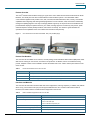
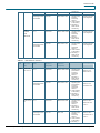
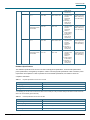
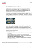
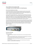
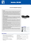
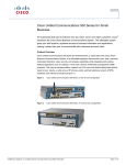
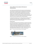
Cisco Unified Communications
500 Series Model 540 for
Small Business
Reference Guide
© 2009 Cisco Systems, Inc. All rights reserved. This document is Cisco Public Information.
Reference Guide
Contents
Product Overview
3
Product Part Numbers
3
Interfaces and Modules
3
Licensing
4
Basic Call Center Capabilities
5
Voice Resource Utilization
5
© 2009 Cisco Systems, Inc. All rights reserved. This document is Cisco Public Information.
Page 2 of 11
Reference Guide
Product Overview
®
The Cisco Unified Communications 540 (Figure 1) part of the Cisco Unified Communications 500 Series for Small
Business, is a critical part of the Cisco Smart Business Communications System. It is an affordable unified
communications appliance that provides voice, data, voicemail, automated attendant, video, security, and wireless
capabilities while integrating with existing desktop applications such as calendar, email, and customer relationship
management (CRM) programs. This easy-to-manage platform supports up to 32 phones and voice mailboxes and
provides flexible deployment options based on your needs, including support for a wide array of IP phones, public
switched telephone network (PSTN) interfaces, and Internet connectivity. This reference guide describes the
specifications and capabilities of the Cisco Unified Communications 540 (UC 540).
Figure 1.
Cisco Unified Communications 540 Models: FXO (Left) and BRI (Right)
Product Part Numbers
The Cisco UC 540 is available in two versions, an FXO (analog) model and a Basic Rate Interface (BRI) base model.
With ease of ordering as a focus area, each has its own product ID. In addition, there is one software licensing
product, multiples of which can be installed to achieve the desired user count. Table 1 lists the part numbers for the
Cisco UC 540.
Table 1.
Product Part Numbers for the Cisco UC 540
Part Number
Description
UC540W-FXO-K9
UC 540 system with 4 FXO, 4 FXS, and 1 voice interface card (VIC) expansion slot
UC540W-BRI-K9
UC 540 system with 2 BRI, 4 FXS, and 1 VIC expansion slot
L-UC-PRO-8U=
Software license upgrade, authorizing an additional 8 users (eDelivery)
Interfaces and Modules
The Cisco UC 540 has built-in interfaces that offer fixed configurations, reducing complexity. In addition, this platform
offers one (1) voice interface card (VIC) slot to support additional Cisco VIC modules. Table 2 lists the built-in
interfaces, and Table 3 lists the modular interfaces supported on the UC 540.
Table 2.
Built-In Interfaces Supported on the Cisco UC 540
Interface
Description
Music-on-hold port
Single 3.5-mm audio port
Onboard Ethernet ports
● Eight 10/100 Mbps LAN
● One 10/100 WAN uplink
● One 10/100 Ethernet expansion port
Integrated inline Power over Ethernet (PoE) ports
8 built-in PoE ports
FXS and direct inward dialing (DID) ports
4 built-in FXS ports (DID is available via the additional module listed in Table 3)
PSTN interfaces (FXO or BRI)
4 FXO or 2 BRI ports
© 2009 Cisco Systems, Inc. All rights reserved. This document is Cisco Public Information.
Page 3 of 11
Reference Guide
WLAN interface
Table 3.
An 802.11b/g access point is integrated into the UC 540, supporting up to 54-Mbps
connections. The access point can be used to provide integrated WLAN connectivity to mobile
clients—voice and data—resulting in mobility and enhanced productivity for users.
Modular VIC Cards for the Cisco UC 540
Part Number
Description
VIC-4FXS/DID, VIC3-4FXS/DID
4-port FXS/DID module
VIC2-2FXS
2-port FXS module
VIC2-2FXO
2-port FXO module
VIC3-2FXS/DID
2-port FXS/DID module
VIC2-4FXO
4-port FXO module
VIC2-2BRI-NT/TE
2-port BRI NT/TE module
VWIC2-1MFT-T1/E1
1-port T1/E1 for voice (ISDN Primary Rate Interface [PRI] and channel associated signaling [CAS]); data is not
supported
Licensing
The Cisco UC 540 includes eight user licenses. These licenses enable the use of Cisco Unified IP Phones and allow
users to access the IP PBX features, including voicemail. In addition, supplementary user licenses are bundled to
help with deployments that need a few extra licenses. For additional licensing needs, the L-UC-PRO-8U may be
ordered. This increases the existing license count by eight. Table 5 lists the number of users supported based on the
hardware/license configurations. The UC 540 also has built-in licenses for unified communications features. Table 4
lists the license count bundled within the system for each feature. Guidance for licenses associated with voice
messaging on the UC 540 is included in Table 6.
Table 4.
Licensing and User Capacity for the Cisco UC 540
License Configuration
Description
UC540W-FXO-K9 or UC540W-BRI-K9
8 user licenses, 2 supplemental user licenses
UC540W-FXO-K9 or UC540W-BRI-K9
and one L-UC-PRO-8U
16 user licenses, 2 supplemental user licenses
UC540W-FXO-K9 or UC540W-BRI-K9
and two L-UC-PRO-8U
24 user licenses, 4 supplemental user licenses
UC540W-FXO-K9 or UC540W-BRI-K9
and three L-UC-PRO-8U
32 user licenses, 4 supplemental user licenses
Table 5.
Feature Licensing for the Cisco UC 540
Feature
Number of Licenses Included
Virtual LANs (VLANs)
5
Service Set Identifiers (SSIDs)
3
Broadcast SSIDs (BSSIDs)
1
VPN tunnels*
10
Remote teleworker sites
10
Users per teleworker site
5
Multisite deployments
5
* Includes IP security (IPSec), Secure Sockets Layer (SSL), or generic routing encapsulation (GRE) tunnels.
© 2009 Cisco Systems, Inc. All rights reserved. This document is Cisco Public Information.
Page 4 of 11
Reference Guide
Table 6.
Voice Messaging Licensing for the Cisco UC 540
Configuration
Voice Messaging Licenses
8-user system
15 mailboxes,* 8 hours of voicemail storage
16-user system
23 mailboxes,* 16 hours of voicemail storage
24-user system
38 mailboxes,* 24 hours of voicemail storage
32-user system
46 mailboxes,* 32 hours of voicemail storage
Sessions to voicemail and automated attendant
6
Internet Message Access Protocol (IMAP) sessions
20
* Any combination of personal mailboxes and general delivery mailboxes can be used.
Basic Call Center Capabilities
The Cisco UC 540 supports basic automatic call distribution (BACD) that can help answer outside calls with
greetings and menus and allow callers to select the appropriate departments. BACD also provides managed call
queues for calls that are waiting to be answered. Table 7 lists the BACD capabilities of the UC 540.
Table 7.
Cisco UC 540 BACD Capabilities
Feature
Number
Hunt groups associated with a BACD
10
Calls allowed in each call queue
30
Agents (members) for each hunt group
20
Statistics accumulated for all BACD groups
168 hours
Hunt groups used with automated attendant
3
In addition to BACD, the Cisco UC 540 integrates with Cisco Unified Contact Center Express (UCCX). UCCX works
with up to a maximum of 12 users (agents and supervisor combined) on the UC 540.
Voice Resource Utilization
The Cisco UC 540 includes four digital signal processors (DSPs) that enable digitized voice processing on the
platform. The DSP resources available on the platform are used for various unified communications features, namely
support of analog and digital VICs, prescheduled or ad hoc voice conference calls, and translation of digitized voice
from a less complex codec (such as g711) to a more complex codec (such as g729)—typically used for deployments
that use IP trunking (SIP or H.323) for PSTN access or multisite interconnection.
Each DSP can support 16 g711 channels or 8 g729 channels. This enables a total of 64 g711 channels on the Cisco
UC 540. Table 8 indicates the DSP resource utilization based on the feature. Tables 9 and 10 show a few
deployment scenarios based on the combination of these features.
© 2009 Cisco Systems, Inc. All rights reserved. This document is Cisco Public Information.
Page 5 of 11
Reference Guide
Table 8.
DSP Resource Utilization on the Cisco UC 540
Feature
DSP Resource Utilization
Support for built-in FXS ports
4 channels
Support for built-in FXO ports
4 channels
Support for built-in music on hold (MoH) port
2 channels
Support for T1/E1 voice/WAN interface card (VWIC)
24 channels*
Transcoding (g711 to g729)
2 channels
Conferencing**
16 channels
* Total DSP resources will depend upon the number of channels provisioned in the T1.
** Conferencing always uses up an entire DSP. The rest of the features can share a DSP. The number of sessions available will
vary depending upon the codec used in a conference call.
Tables 9 and 10 list maximum sessions for either ad hoc conferencing or meet-me conferencing. DSP resources
allocated for conferencing can be shared by both features, and a mix of these can be configured. Below are a few
examples based on Table 9. The concept of sharing conferencing resources applies to Table 10 as well.
Ad hoc 24x8
Meet-me 0x0
Ad hoc 12x8
Meet-me 12x8
Ad hoc 24x4
Meet-me 6x16
The Transcoding column lists the maximum transcoding sessions that the system can be configured for, for a given
configuration of DSP. For example, the first row in Table 9 indicates that a maximum of three transcoding sessions
are available if three DSPs are allocated for conferencing.
If more transcoding sessions are required, DSP resources will need to be diverted from conferencing to transcoding.
For example, in the second row of Table 9, one of the DSPs is dedicated to transcoding, leaving two DSPs for
conferencing. Notice the increase in the number of transcoding sessions and the drop in the number of conferencing
sessions.
Table 9.
DSP Resources: Scenario 1
UC 500
Model
Additional
Voice Card
(VIC)
SIP Trunk Preferred
Codec
Ad-hoc Conference
(Sessions x
Participants)
Meet-me Conference
(Sessions x
Participants)
UC 540
None
No SIP Trunk or
G.711
Up to a maximum of
24x8 or 48x4
Up to a maximum of
24x8 or 12x16 or 6x32
● 1 DSP for
supporting voice
ports and
Transcoding
sessions
● Remaining 3
DSPs used for
Conferencing
A maximum of 3
Transcoding sessions
for this configuration
G.729
Up to a maximum of
4x8 or 8x4
Up to a maximum of
4x8 or 2x16 or 1x32
● 1 DSP for
supporting voice
ports and
Transcoding
sessions
● 1 DSP reserved
for transcoding
● Remaining 2
DSPs used for
Conferencing
A maximum of 11
Transcoding sessions
for this configuration
Up to a maximum of
24x8 or 48x4
Up to a maximum of
24x8 or 12x16 or 6x32
● 1 DSP for
supporting voice
ports and
Transcoding
sessions
● Remaining 3
DSPs used for
A maximum of 2
Transcoding sessions
for this configuration
Transcoding sessions
recommended
2FXS
2FXS/DID
No SIP Trunk or
G.711
2FXO
© 2009 Cisco Systems, Inc. All rights reserved. This document is Cisco Public Information.
Comments
Transcoding
Page 6 of 11
Reference Guide
Conferencing
Up to a maximum of
4x8 or 8x4
Up to a maximum of
4x8 or 2x16 or 1x32
● 1 DSP for
supporting voice
ports and
Transcoding
sessions
● 1 DSP reserved
for transcoding
● Remaining 2
DSPs used for
Conferencing
A maximum of 10
Transcoding sessions
for this configuration
No SIP Trunk or
G.711
Up to a maximum of
24x8 or 48x4
Up to a maximum of
24x8 or 12x16 or 6x32
● 1 DSP for
supporting voice
ports and
Transcoding
sessions
● Remaining 3
DSPs used for
Conferencing
A maximum of 1
Transcoding sessions
for this configuration
G.729
Up to a maximum of
4x8 or 8x4
Up to a maximum of
4x8 or 2x16 or 1x32
● 1 DSP for
supporting voice
ports and
Transcoding
sessions
● 1 DSP reserved
for transcoding
● Remaining 2
DSPs used for
Conferencing
A maximum of 9
Transcoding sessions
for this configuration
G.729
Transcoding sessions
recommended
4FXS
4FXS/DID
4FXO
2BRI NT/TE
Transcoding sessions
recommended
Table 10.
DSP Resources: Scenario 2
UC 500
Model
Additional
Voice Card
(VIC)
SIP Trunk Preferred
Codec
Ad-hoc Conference
(Sessions x
Participants)
Meet-me Conference
(Sessions x
Participants)
UC 540
1MFT T1/E1
No SIP Trunk of
G.711
Up to a maximum of
24x8 or 48x4
Up to a maximum of
24x8 or 12x16 or 6x32
No. of Ch ≤ 6
G.729
Transcoding sessions
recommended
1MFT T1/E1
6 ≤ No. of Ch ≤
22
No SIP Trunk or
G.711
G.729
Transcoding sessions
recommended
Up to a maximum of
4x8 or 8x4
Up to a maximum of
16x8 or 32x4
Up to a maximum of
2x8 or 4x4
© 2009 Cisco Systems, Inc. All rights reserved. This document is Cisco Public Information.
Up to a maximum of
4x8 or 2x16 or 1x32
Up to a maximum of
16x8 or 8x16 or 4x32
Up to a maximum of
2x8 or 1x16
Comments
Transcoding
● 1 DSP for
supporting voice
ports fractional
T1/E1 and
Transcoding
sessions
● Remaining 3
DSPs used for
Conferencing
0 session for 6 ch
● 1 DSP for
supporting voice
ports fractional
T1/E1 and
Transcoding
sessions
● 1 DSP reserved
for transcoding
● Remaining 2
DSPs used for
Conferencing
8 session for 6 ch
● 2 DSP for
supporting voice
ports and
Transcoding
sessions
● Remaining 2
DSPs used for
Conferencing
0 session for 22 ch
● 2 DSP for
supporting voice
ports and
Transcoding
sessions
● 1 DSP reserved
for transcoding
● Remaining 1
8 session for 22 ch
1 session for 4 ch
2 sessions for 2 ch
9 session for 4 ch
10 sessions for 2 ch
1 session for 20 ch
2 sessions for 18 ch
And so on…
9 session for 20 ch
10 sessions for 18 ch
And so on…
Page 7 of 11
Reference Guide
DSPs used for
Conferencing
1MFT Full T1
No SIP Trunk or
G.711
Up to a maximum of
8x8 or 16x4
Up to a maximum of
8x8 or 4x16 or 1x32
● 3 DSP for
supporting voice
ports and
Transcoding
sessions
● Remaining 1
DSPs used for
Conferencing
A maximum of 7
Transcoding sessions,
disable Conferencing
for more transcoding
G.729
Up to a maximum of
2x8 or 4x4
Up to a maximum of
2x8 or 1x16
● 3 DSP for
supporting voice
ports and
Transcoding
sessions
● 0 DSP reserved
for transcoding
● Remaining 1
DSPs used for
Conferencing
A maximum of 7
Transcoding sessions,
disable Conferencing
for more transcoding
No SIP Trunk or
G.711
Up to a maximum of
8x8 or 16x4
Up to a maximum of
8x8 or 4x16 or 1x32
● 3 DSP for
supporting voice
ports and
Transcoding
sessions
● Remaining 1
DSPs used for
Conferencing
A maximum of 4
Transcoding sessions,
disable Conferencing
for more transcoding
G.729
Up to a maximum of
2x8 or 4x4
Up to a maximum of
2x8 or 1x16
● 3 DSP for
supporting voice
ports and
Transcoding
sessions
● 0 DSP reserved
for transcoding
● Remaining 1
DSPs used for
Conferencing
A maximum of 4
Transcoding sessions,
disable Conferencing
for more transcoding
Transcoding sessions
recommended
1MFT Full T1
Transcoding sessions
recommended
Hardware Specifications
The hardware specifications for the Cisco UC 540 include physical specifications, environmental specifications,
power specifications, and regulatory compliance. Table 11 lists the physical specifications. Table 12 lists the power
requirements for the platform. Table 13 provides the environmental specifications, and Table 14 shows the
compliance information.
Table 11.
Physical Specifications for the Cisco UC 540
Feature
Description
Packaging type
Desktop form factor
Console port (up to 115.2 kbps)
1
Auxiliary port*
1
* The auxiliary port on the Cisco UC 540 is the same as the console port. The port has an ability to auto-detect modem tones and
switch over to the auxiliary port functionality.
Table 12.
Power Specifications for the Cisco UC 540
Feature
Description
AC input voltage
100 to 240V AC
AC input frequency
50 to 60 Hz
AC input current
4 to 2A (100 to 240V)
AC input surge current
50 to 100A (100 to 240V)
© 2009 Cisco Systems, Inc. All rights reserved. This document is Cisco Public Information.
Page 8 of 11
Reference Guide
Maximum inline power distribution
82W
Power dissipation (AC without IP phone)
80W
90W (including external adapter)
Power dissipation (AC with IP phone)
175W
180W (including external adapter)
Table 13.
Environmental Specifications for the Cisco UC 540
Feature
Description
Operating temperature
32o to 104oF
Operating humidity
10% to 85% noncondensing, operating
5% to 95% noncondensing, nonoperating
Nonoperating temperature
4 o to 149oF (–20o to 65oC)
Operation altitude
104oF (40oC) at sea level
87.8oF (31oC) at 6000 ft (1800 m)
77oF (25oC) at 10,000 ft (3000 m)
34.7oF (1.5oC) per 1000 ft
Dimension (H x W x D)
2.625 x 10.5 x 11.05 in.
(6.67 x 26.67 x 28.07 cm)
Power supply dimensions (H x W x D)
1.7 x 4 x 7.5 in.
(4.3 x 10.16 x 19.05 cm)
Rack height
1.5 rack unit (RU)
Weight (fully configured)
8 lb (3.63 kg)
Power supply weight
3 lb (1.36 kg)
Noise level (minimum and maximum)
Normal operating temperature:
< 78°F (25.6°C): 34 dBA
> 78°F (25.6°C) through < 104°F (40°C): 37 dBA
> 104°F (40°C): 42 dBA
Table 14.
Category
Safety
Regulatory Compliance for the Cisco UC 540
Compliance
● IEC 60950-1
● AS/NZS 60950.1
● CAN/CSA-C22.2 No. 60950-1
● EN 60950-1
● UL 60950-1
Immunity
● EN 55024
● EN 300-386
● EN 61000-6-2
● EN 50082-1
● EN 55024 (CISPR 24)
© 2009 Cisco Systems, Inc. All rights reserved. This document is Cisco Public Information.
Page 9 of 11
Reference Guide
Electromagnetic compatibility (EMC)
● FCC Part 15, ICES-003
● EN55022, CISPR 22
● AS/NZS
● CNS13438
● VCCI V-3
● EN 55024
● EN 300-386
● EN 61000-3-2
● EN 61000-3-3
● EN 50082-1
● EN 55024 (CISPR 24)
● EN 61000-4-2
● EN 61000-4-3
● EN 61000-4-4
● EN 61000-4-5
● EN 61000-4-6
● EN 61000-4-8
● EN 61000-4-11
● EN 61000-6-2
Telecommunications
● FXS/DID
● TIA-968-A3
● CS-03 Part I
● ACIF S002
● ACIF S003
● ANZ PTC200
● ISDN BRI S/T (voice and data BC)
● TIA-968-A3
● CS-03 Part VI
● TBR3
● ACIF S031
● ANZ PTC200
● MPMHAPT Japan Digital
● FXO
● TIA-968-A3
● CS-03 Part I
● TBR21
● MPMHAPT Japan Analog
● ACIF S002
● ACIF S003
● ACIF S004
● ANZ PTC200
● MOH interface
● ACIF S038
● ACIF S004
● TIA-464C
© 2009 Cisco Systems, Inc. All rights reserved. This document is Cisco Public Information.
Page 10 of 11
Reference Guide
Printed in USA
© 2009 Cisco Systems, Inc. All rights reserved. This document is Cisco Public Information.
C78-557768-00
09/09
Page 11 of 11