1
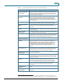
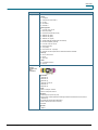
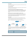
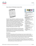
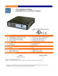
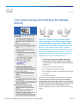
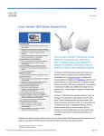
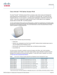
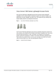
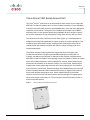
Data Sheet
Cisco Aironet 1250 Series Access Point
®
®
The Cisco Aironet 1250 Series is the first enterprise-class access point to support the
IEEE 802.11n draft 2.0 standard. 802.11n offers combined data rates of up to 600 Mbps
to provide users with mobile access to high-bandwidth data, voice, and video applications
regardless of their location. Through the use of multiple-input multiple-output (MIMO)
technology, 802.11n also provides reliable and predictable WLAN coverage to improve
the end-user experience for both existing 802.11a/b/g clients and new 802.11n clients.
®
The robust Cisco Aironet 1250 Series Access Point (Figure 1) is a modular platform
designed to be easily field-upgradeable to support a variety of wireless capabilities. This
modularity allows businesses to deploy existing wireless technologies today with the
confidence that their network investment will extend to support emerging and future
wireless technologies.
The platform was specifically engineered to support the power, throughput, and
mechanical requirements of higher-speed WLAN technologies, including 802.11n.
Currently, the platform provides both 2.4-GHz and 5-GHz modules compliant with the
IEEE 802.11n draft 2.0 standard. As technology evolves, the platform is flexible to support
future radio modules designed to deliver intelligent RF services, further enhancing the
performance and reliability of the wireless network. The Cisco Aironet 1250 Series is a
rugged indoor access point designed for both office and challenging RF environments
such as factories, warehouses, hospitals and large retail establishments that require the
antenna versatility associated with connectorized antennas, a rugged metal enclosure,
and a broad operating temperature range. With a Gigabit Ethernet (10/100/1000)
interface, the Cisco Aironet 1250 Series delivers line-rate throughput for higher-speed
WLAN technologies such as 802.11n. The access point offers the flexibility of inline as
well as local power options.
Figure 1.
The Cisco Aironet 1250 Series Access Point
All contents are Copyright © 1992–2007 Cisco Systems, Inc. All rights reserved. This document is Cisco Public Information.
Page 1 of 13
Data Sheet
The Cisco Aironet 1250 Series is part of the Cisco Unified Wireless Network. The Cisco Unified
Wireless Network is a comprehensive solution that unifies the wired and wireless network to
deliver a common set of services and applications, providing users a single experience for any
mode of network connectivity, and offering IT simplified operational management. The Cisco
Aironet 1250 Series integrates seamlessly with the Cisco Unified Wireless Network. It extends the
same industry-leading RF and network management capabilities as currently available across the
breadth of Cisco wireless solutions.
The Cisco Aironet 1250 Series has two deployment options: controller-based (unified) or
standalone (autonomous). Access points using the Lightweight Access Point Protocol (LWAPP)
work in conjunction with Cisco wireless LAN controllers and optionally with the Cisco Wireless
Control System (WCS). When configured with LWAPP, the Cisco Aironet 1250 Series simplifies
operations by automatically detecting the best-available Cisco Wireless LAN Controller and
downloading appropriate policies and configuration information with no manual intervention. When
deployed as a standalone access point, the Cisco Aironet 1250 Series delivers a baseline set of
features and can later be software-upgraded to take advantage of the full benefits of the Cisco
Unified Wireless Network.
Investment Protection
The Cisco Aironet 1250 Series is a modular platform that is compliant with the 802.11n draft 2.0
standard and is the first Wi-Fi CERTIFIED 802.11n draft 2.0 access point. Furthermore, the
platform has been tested extensively to ensure simple, secure interoperability with IEEE 802.11n
draft 2.0 standard devices. The Cisco Aironet 1250 Series provides additional investment
protection with its modular, field-upgradeable design and easy-to-install radio modules. Cisco is
committed to standards, and the Cisco Aironet 1250 Series provides a path for compliance to the
final IEEE 802.11n standard, once ratified. Businesses with an immediate need to enhance the
performance of their WLANs can deploy the IEEE 802.11n draft 2.0 standard radio modules now
with the confidence that their investments are protected. These modules can be easily fieldupgraded should this be required by a shift in standards evolution.
Award-Winning Security
The Cisco Aironet 1250 Series supports industry-standard wireless security protocols, including
802.11i, Wi-Fi Protected Access (WPA), WPA2, and 802.1X, along with numerous Extensible
Authentication Protocol (EAP) types. The access point delivers hardware-accelerated Advanced
Encryption Standard (AES) encryption designed to meet the most stringent enterprise and
government encryption requirements without compromising performance. As part of the Cisco
Secure Wireless Solution, Cisco Aironet 1250 Series Access Points operating with LWAPP enable
comprehensive wired and wireless intrusion prevention and detection. Each access point can scan
the RF environment and report on suspicious or unauthorized wireless activity, effectively allowing
businesses to create a comprehensive threat defense across 802.11a/b/g and now 802.11n.
Additionally, the Cisco Aironet 1250 Series Access Point supports management frame protection
for the encryption of 802.11 management frames by the wireless network infrastructure. This
allows the network to completely remove the threat from man-in-the-middle and spoofing attacks. If
an access point detects a malicious attack, an alarm will be generated and reported to the network
administrator.
All contents are Copyright © 1992–2007 Cisco Systems, Inc. All rights reserved. This document is Cisco Public Information.
Page 2 of 13
Data Sheet
RF Management
Cisco incorporates unique capabilities within its wireless solution that address the operational
challenges of deploying business wireless networks. At the heart of these capabilities are
intelligent Radio Resource Management (RRM) algorithms designed to consistently fine-tune
WLAN parameters to best meet ongoing performance requirements. RRM allows the Cisco Unified
Wireless Network to continuously analyze the existing RF environment and automatically adjust
access point power and channel settings to help mitigate such things as co-channel interference
and signal coverage problems. Unlike conventional 802.11a/b/g products, the Cisco Aironet 1250
Series uses multiple-input multiple-output (MIMO) technology to take advantage of the effects of
RF multipath propagation in order to improve the reliability and predictability of the wireless signal.
The Cisco Aironet 1250 Series supports the latest U.S. and European requirements for Dynamic
Frequency Selection (DFS), ensuring the access point accurately detects radar events and makes
full use of the available 5-GHz spectrum. In addition, the Cisco Aironet 1250 Series supports a
Software Defined Radio (SDR) enabling it to be upgraded in the field to support new frequencies
and power levels as they are approved for use. These RF management capabilities increase
system capacity, perform automated self-healing to compensate for RF dead zones and access
point failures, and provide a comprehensive way to manage one of your most precious assets,
your corporate spectrum.
Deployment Scenarios
The Cisco Aironet 1250 Series with support for the 802.11n draft 2.0 standard is ideal for a variety
of deployment scenarios across many industries. The improved throughput, reliability, and
predictability of an 802.11n network meet the requirements that many companies have for moving
towards a truly mobile enterprise. Cisco’s next-generation wireless technology is especially
beneficial for environments with the following characteristics:
●
Challenging RF environments (for example, manufacturing plants, warehouses, clinical
environments)
●
Bandwidth-intensive applications (for example, digital imaging, file transfers, network
backup)
●
Real-time, latency-sensitive applications including voice and video
●
Environments that need to support existing 802.11a/b/g and new 802.11n wireless clients
Designed for critical business environments and installations that require antenna versatility, the
Cisco Aironet 1250 Series features antenna connectors for improved coverage and aesthetically
pleasing installation options. The UL2043 rating of the Cisco Aironet 1250 Series allows the
access points to be placed above the ceiling tile in plenum areas regulated by municipal fire codes
or suspended from drop ceilings.
Features and Benefits
Table 1 lists the features and benefits of Cisco Aironet 1250 Series Access Points.
All contents are Copyright © 1992–2007 Cisco Systems, Inc. All rights reserved. This document is Cisco Public Information.
Page 3 of 13
Data Sheet
Table 1.
Features and Benefits of Cisco Aironet 1250 Series Access Points
Feature
Benefit
Data Rates of up to 300
Mbps per Radio, 600 Mbps
per Access Point
The 802.11n draft 2.0 standard provides capabilities such as 40-MHz channels, packet
aggregation, and block acknowledgement which significantly increase the amount of
bandwidth available for user applications. With support for physical layer (PHY) data
rates up to 300 Mbps per radio, this represents a greater than five-fold increase over
the performance of 802.11a/g networks.
Enhanced Reliability and
Predictability
MIMO technology, with its multiple antennas and advanced signal processing,
improves coverage, reduces dead spots, and augments overall client throughput.
MIMO also enables higher data rates by transmitting multiple spatial streams across
the unique paths formed between devices. Enhanced reliability and throughput
provides a better overall end-user experience for users relying on the wireless network
for business functions.
Powerful Platform
Engineered to support the power, thermal dissipation, memory, CPU, and Gigabit
Ethernet transmission requirements of 802.11n and future wireless technologies.
Modular Field-Upgradeable
Design with Easy-to-Install
Modules
Investment protection through field-upgradeable radios. As technology evolves, radio
modules can be replaced in the field with new radio modules, preserving the
investment in the access point chassis and avoiding the expense of installing a new
access point.
2.4-GHz and 5-GHz Radio
Modules
Dual radios allow simultaneous operation of 2.4-GHz and 5-GHz wireless networks,
offering the greatest number of available channels and therefore the greatest system
capacity and scalability.
Both Inline and Local
Powering Options
To realize optimal performance, the access point supports both inline power delivered
over a single Ethernet cable and local power options.
Extensive Interoperability
The Aironet 1250 Series Access Point has undergone extensive interoperability testing
to ensure simple, secure interoperability with other 802.11 devices. It is the first Wi-Fi
CERTIFIED 802.11n draft 2.0 access point, has earned the Intel Connect with Centrino
certification, and has undergone extensive testing in 802.11n plug fests.
Backward Compatibility with
Existing 802.11a/b/g Clients
Protects existing 802.11a/b/g investments and provides an easy migration to 802.11n.
Integrated RF Management
Capabilities
Integrated RF management capabilities address the operational challenges of
deploying business wireless networks. These capabilities include Radio Resource
Management, MIMO, superior DFS support, SDR certification, and spectrum
intelligence integration into WCS. Integrated RF management capabilities increase
system capacity, improve system performance, perform automated self-healing to
compensate for RF dead zones and access point failures, and provide a
comprehensive way to manage one of your most precious assets, your corporate
spectrum.
Supports up to 24 non1
Overlapping Channels
Provides lower potential interference with neighboring access points, which simplifies
deployment and reduces co-channel interference for fewer transmission errors and
greater throughput. More channels also means that more of the high- throughput, 40MHz channels introduced in the 802.11n draft 2.0 standard are supported.
External RP-TNC Antenna
Connectors for Both 2.4-GHz
and 5-GHz Radios
Antenna connectors support a variety of Cisco 2.4-GHz and 5-GHz antennas, providing
range and coverage versatility.
Cisco Unified IDS/IPS
An integral part of the Cisco Secure Wireless Solution, the industry’s first integrated
wired and wireless security solution, the access point can monitor the RF environment
to detect and locate unauthorized wireless activity, including rogue access points and
RF denial of service attacks.
Management Frame
Protection
Management frame protection encrypts the management header of the 802.11 packet
and enables the access point to detect spoofed frames from malicious users
impersonating infrastructure access points. If an access point detects a malicious
attack, an alert will be generated and reported back to the network administrator.
Rugged Metal Housing
The access point is built with a metal case and sturdy features for deployment in
rugged environments such as factories, warehouses, and other industrial
environments.
UL 2043 Plenum Rating and
Extended Operating
Temperature
Supports installation in environmental air spaces, such as areas above suspended
ceilings.
Multipurpose and Lockable
Mounting Bracket
Provides flexibility during site survey and traditional installation as well as helping to
deter theft.
1
Supports 3 2.4-GHz and 21 5-GHz channels in the FCC regulatory domain; channel support varies by
country. See Table 2 for frequency band and operating channel support in your particular regulatory domain.
All contents are Copyright © 1992–2007 Cisco Systems, Inc. All rights reserved. This document is Cisco Public Information.
Page 4 of 13
Data Sheet
Summary
The Cisco Aironet 1250 Series Access Point is the first enterprise-class access point to support
the IEEE 802.11n draft 2.0 standard. With its modular design, the Cisco Aironet 1250 Series
Access Point supports current and future wireless technologies, ensuring investment protection.
With both 2.4-GHz and 5-GHz 802.11n draft 2.0 standard radio modules, the access point delivers
total data rates of up to 600 Mbps, meeting the performance requirements of the most demanding
applications. Integrated MIMO technology provides more reliable coverage and greater throughput
for both existing 802.11a/b/g clients and new 802.11n clients in even the most challenging wireless
environments. Users can now rely on wireless networks to give them a similar experience to wired
networks, providing them with mobile access to high-bandwidth data, voice, and video applications
regardless of their location.
Product Specifications
Table 2 lists the product specifications for Cisco Aironet 1250 Series Access Points.
Table 2.
Product Specifications for Cisco Aironet 1250 Series Access Points
Item
Specification
Part Numbers
Access point platform with pre-installed radio modules:
● AIR-AP1252AG-x-K9 802.11a/g/n-draft 2.0 2.4/5-GHz Modular Autonomous AP; 6 RP-TNC
● AIR-AP1252G-x-K9 802.11g/n-draft 2.0 2.4-GHz Modular Autonomous AP; 3 RP-TNC
● AIR-LAP1252AG-x-K9 802.11a/g/n-draft 2.0 2.4/5-GHz Modular Unified AP; 6 RP-TNC
● AIR-LAP1252G-x-K9 802.11g/n-draft 2.0 2.4-GHz Modular Unified AP; 3 RP-TNC
Individual components:
● AIR-AP1250= Modular Auto AP Platform (no radio modules); Spare
● AIR-LAP1250= Modular Unified AP Platform (no radio modules); Spare
● AIR-RM1252A-x-K9= 802.11a/n-d2.0 5-GHz Radio Module; 3 RP-TNC
● AIR-RM1252G-x-K9= 802.11g/n-d2.0 2.4-GHz Radio Module; 3 RP-TNC
● AIR-AP1250MNTGKIT= 1250 Series Ceiling, Wall Mount Bracket kit- Spare
Regulatory domains: (x = regulatory domain)
● A = FCC
● C = China
● E = ETSI
● I = Israel
● K = Korea
● N =Non-FCC
● P = Japan2
● S = Singapore
● T = Taiwan
Customers are responsible for verifying approval for use in their individual countries. To verify approval
and to identify the regulatory domain that corresponds to a particular country, please visit:
http://www.cisco.com/go/aironet/compliance.
Not all regulatory domains have been approved. As they are approved, the part numbers will be available
on the Global Price List.
Software
● Cisco IOS Software Release 12.4(10b)JA or later (Autonomous Mode).
● Cisco IOS Software Release 12.4(10b)JX or later (Unified Mode).
● Cisco Unified Wireless Network Software Release 4.2 or later.
Draft 802.11n
Version 2.0 (and
Related)
Capabilities
● 2x3 MIMO with two spatial streams
● Maximal Ratio Combining (MRC)
● Legacy beamforming (hardware supports this capability; not yet enabled in software)
● 20-and 40-MHz channels
● PHY data rates up to 300 Mbps
● Packet aggregation: A-MPDU (Tx/Rx), A-MSDU (Tx/Rx)
● 802.11 DFS (Bin 5)
● Cyclic Shift Diversity (CSD) support
All contents are Copyright © 1992–2007 Cisco Systems, Inc. All rights reserved. This document is Cisco Public Information.
Page 5 of 13
Data Sheet
Item
Specification
Data Rates
Supported
802.11a: 6, 9, 12, 18, 24, 36, 48, and 54 Mbps
802.11g: 1, 2, 5.5, 6, 9, 11, 12, 18, 24, 36, 48, and 54 Mbps
802.11n data rates (2.4 GHz and 5 GHz):
2
MCS Index
3
GI = 800ns
20-MHz Rate
(Mbps)
Frequency Band
and 20-MHz
Operating
Channels
GI = 400ns
40-MHz Rate
(Mbps)
20-MHz Rate
(Mbps)
40-MHz Rate
(Mbps)
0
6.5
13.5
7.2
15
1
13
27
14.4
30
2
19.5
40.5
21.7
45
3
26
54
28.9
60
4
39
81
43.3
90
5
52
108
57.8
120
6
58.5
121.5
65
135
7
65
135
72.2
157.5
8
13
27
14.4
30
9
26
54
28.9
60
10
39
81
43.3
90
11
52
108
57.8
120
12
78
162
86.7
180
13
104
216
115.6
240
14
117
243
130
270
15
130
270
144.4
300
-A (Americas (FCC)):
● 2.412 to 2.462 GHz; 11 channels
● 5.180 to 5.320 GHz; 8 channels
● 5.500 to 5.700 GHz, 8 channels (excludes
5.600 to 5.640 GHz)
● 5.745 to 5.825 GHz; 5 channels
-C (China):
● 2.412 to 2.472 GHz; 13 channels
-N (Non-FCC):
● 2.412 to 2.462 GHz; 11 channels
● 5.180 to 5.320 GHz; 8 channels
● 5.745 to 5.825 GHz; 5 channels
-P (Japan2):
● 2.412 to 2.472 GHz; 13 channels
● 5.180 to 5.320 GHz; 8 channels
● 5.745 to 5.825 GHz; 5 channels
-S (Singapore):
● 2.412 to 2.472 GHz; 13 channels
-E (ETSI):
● 2.412 to 2.472 GHz; 13 channels
● 5.180 to 5.320 GHz; 8 channels
● 5.745 to 5.825 GHz; 5 channels
● 5.180 to 5.320 GHz; 8 channels
● 5.500 to 5.700 GHz, 11 channels
-T (Taiwan):
● 2.412 to 2.462 GHz; 11 channels
-I (Israel):
● 2.412 to 2.472 GHz, 13 channels
● 5.280 to 5.320 GHz; 3 channels
● 5.500 to 5.700 GHz, 11 channels
● 5.180 to 5.320 GHz; 8 channels
● 5.745 to 5.825 GHz; 5 channels
-K (Korea):
● 2.412 to 2.472 GHz; 13 channels
● 5.180 to 5.320 GHz; 8 channels
● 5.500 to 5.620 GHz, 7 channels
● 5.745 to 5.805 GHz, 4 channels
Note: This varies by regulatory domain. Refer to the product documentation for specific details for each regulatory domain.
2
MCS Index: The Modulation and Coding Scheme (MCS) index determines the number of spatial streams, the
modulation, the coding rate, and data rate values.
GI: A Guard Interval (GI) between symbols helps receivers overcome the effects of multipath delays.
3
All contents are Copyright © 1992–2007 Cisco Systems, Inc. All rights reserved. This document is Cisco Public Information.
Page 6 of 13
Data Sheet
Item
Specification
Maximum
Number of NonOverlapping
Channels
2.4 GHz
● 802.11b/g:
5 GHz
● 802.11a:
◦ 20 MHz: 21
● 802.11n:
◦ 20 MHz: 3
● 802.11n:
◦
20 MHz: 3
◦
20 MHz: 21
◦
40 MHz: 1
◦
40 MHz: 9
Note: This varies by regulatory domain—refer to the product documentation for specific details for each regulatory domain.
Receive
Sensitivity
802.11a
802.11b
802.11g
–86 dBm @ 6 Mb/s
–90 dBm @ 1 Mb/s
–87 dBm @ 6 Mb/s
–85 dBm @ 9 Mb/s
–89 dBm @ 2 Mb/s
–86 dBm @ 9 Mb/s
–82 dBm @ 12 Mb/s
–87 dBm @ 5.5 Mb/s
–83 dBm @ 12 Mb/s
–81 dBm @ 18 Mb/s
–85 dBm @ 11 Mb/s
–82 dBm @ 18 Mb/s
–80 dBm @ 24 Mb/s
–81 dBm @ 24 Mb/s
–79 dBm @ 36 Mb/s
–80 dBm @ 36 Mb/s
–74 dBm @ 48 Mb/s
–75 dBm @ 48 Mb/s
–74 dBm @ 54 Mb/s
–73 dBm @ 54 Mb/s
Maximum
Transmit Power
2.4-GHz
5-GHz
5-GHz
2.4-GHz
802.11n (HT20)
802.11n (HT40)
802.11n (HT20)
802.11n (HT40)
–85 dBm @ MC0
–85 dBm @ MC0
–86 dBm @ MC0
–86 dBm @ MC0
–84 dBm @ MC1
–84 dBm @ MC1
–85 dBm @ MC1
–85 dBm @ MC1
–83 dBm @ MC2
–83 dBm @ MC2
–84 dBm @ MC2
–84 dBm @ MC2
–82 dBm @ MC3
–79 dBm @ MC3
–83 dBm @ MC3
–80 dBm @ MC3
–79 dBm @ MC4
–76 dBm @ MC4
–80 dBm @ MC4
–77 dBm @ MC4
–74 dBm @ MC5
–71 dBm @ MC5
–75 dBm @ MC5
–72 dBm @ MC5
–73 dBm @ MC6
–70 dBm @ MC6
–74 dBm @ MC6
–71 dBm @ MC6
–72 dBm @ MC7
–69 dBm @ MC7
–73 dBm @ MC7
–70 dBm @ MC7
–85 dBm @ MC8
–85 dBm @ MC8
–86 dBm @ MC8
–86 dBm @ MC8
–84 dBm @ MC9
–84 dBm @ MC9
–85 dBm @ MC9
–85 dBm @ MC9
–83 dBm @ MC10
–83 dBm @ MC10
–84 dBm @ MC10
–84 dBm @ MC10
–82 dBm @ MC11
–79 dBm @ MC11
–83 dBm @ MC11
–80 dBm @ MC11
–79 dBm @ MC12
–76 dBm @ MC12
–80 dBm @ MC12
–77 dBm @ MC12
–74 dBm @ MC13
–71 dBm @ MC13
–75 dBm @ MC13
–72 dBm @ MC13
–73 dBm @ MC14
–70 dBm @ MC14
–74 dBm @ MC14
–71 dBm @ MC14
–72 dBm @ MC15
–69 dBm @ MC15
–73 dBm @ MC15
–70 dBm @ MC15
2.4GHz
● 802.11b
5GHz
● 802.11a
◦ 23 dBm with 1 antenna
● 802.11g
◦ 17 dBm with 1 antenna
● 802.11n non-HT duplicate (802.11a duplicate) mode
◦ 20 dBm with 1 antenna
● 802.11n (HT20)
◦ 17 dBm with 1 antenna
● 802.11n (HT20)
◦
17 dBm with 1 antenna
◦
◦
20 dBm with 2 antennas
◦
● 802.11n (HT40)
17 dBm with 1 antenna
20 dBm with 2 antennas
● 802.11n (HT40)
◦
17 dBm with 1 antenna
◦
17 dBm with 1 antenna
◦
20 dBm with 2 antennas
◦
20 dBm with 2 antennas
Note: The maximum power setting will vary by channel and according to individual country regulations. Refer to the product
documentation for specific details.
All contents are Copyright © 1992–2007 Cisco Systems, Inc. All rights reserved. This document is Cisco Public Information.
Page 7 of 13
Data Sheet
Item
Specification
Available
Transmit Power
Settings
2.4GHz
5GHz
23 dBm (200 mW)
20 dBm (100 mW)
20 dBm (100 mW)
17 dBm (50 mW)
17 dBm (50 mW)
14 dBm (25 mW)
14 dBm (25 mW)
11 dBm (12.5 mW)
11 dBm (12.5 mW)
8 dBm (6.25 mW)
8 dBm (6.25 mW)
5 dBm (3.13 mW)
5 dBm (3.13 mW)
2 dBm (1.56 mW)
2 dBm (1.56 mW)
–1 dBm (0.78 mW)
–1 dBm (0.78 mW)
Note: The maximum power setting will vary by channel and according to individual country regulations. Refer to the product
documentation for specific details.
Antenna
Connectors
● 2.4-GHz: 3 RP-TNC connectors
● 5-GHz: 3 RP-TNC connectors
Interfaces
● 10/100/1000BASE-T autosensing (RJ-45)
● Management console port (RJ45)
Indicators
● Status LED indicates operating state, association status, error/warning condition, boot sequence, and
maintenance status.
● Ethernet LED indicates activity over the Ethernet, status.
Modularity
● Number of radio module slots: 2
● Available radio modules
● Radio LED indicates activity over the radio, status.
Part Number
Description
Maximum per
AP1250 platform
AIR-RM1252A-x-K9
2.4 802.11a/n-d2.0 5-GHz Radio Module; 3 RP-TNC
1
AIR-RM1252G-x-K9
802.11g/n-d2.0 2.4-GHz Radio Module; 3 RP-TNC
1
Dimensions
(W x L x H)
● AP (without mounting bracket): 8.12 x 9.52 x 2.35 in. (20.62 x 24.18 x 5.97 cm)
● AP (with mounting bracket): 8.12 x 9.52 x 2.75 in. (20.62 x 24.18 x 6.99 cm)
Weight
● AP with 2 radios installed: 5.1 lbs (2.31 kg)
● AP chassis: 2.1 lbs (0.95 kg)
● 2.4 GHz radio: 1.5 lbs (0.68 kg)
● 5 GHz radio: 1.5 lbs (0.68 kg)
Environmental
Non-operating (storage) temperature: –40 to 185°F (–40 to 85°C)
Operating temperature: –4 to +131°F (–20 to +55°C)
Operating humidity: 10 to 90 percent (non-condensing)
System Memory
● 64 MB DRAM
● 32 MB flash
Input Power
Requirements
● AP1250: 36 to 57 VDC
● Power Supply and Power Injector: 100 to 240 VAC; 50 to 60 Hz
Powering
Options
● Cisco Catalyst switch port capable of sourcing 18.5W or greater
● Cisco AP1250 Power Injector (AIR-PWRINJ4)
● Cisco AP1250 Local Power Supply (AIR-PWR-SPLY1)
● 802.3af switch (AP1250 with single radio only)
Power Draw
● AP1250 with two RM1252 radio modules installed: 16.9 W
● AP1250 with one RM1252 radio module installed: 12.95 W
Note: For an AP1250 with two radios, 16.9 W is the maximum power required at the access point
(powered device). When deployed using PoE, the power drawn from the power sourcing equipment will be
higher by some amount dependent on the length of the interconnecting cable. This additional power may
be as high as 1.6W, bringing the total system power draw (access point + cabling) to 18.5 W. A similar
consideration applies for an AP1250 with one radio.
Warranty
90 days
All contents are Copyright © 1992–2007 Cisco Systems, Inc. All rights reserved. This document is Cisco Public Information.
Page 8 of 13
Data Sheet
Item
Specification
Compliance
Standards
● Safety:
◦
UL 60950-1
◦
CAN/CSA-C22.2 No. 60950-1
◦
UL 2043
◦
IEC 60950-1
◦
EN 60950-1
● Radio approvals:
◦
FCC Part 15.247, 15.407
◦
RSS-210 (Canada)
◦
EN 300.328, EN 301.893 (Europe)
◦
ARIB-STD 33 (Japan)
◦
ARIB-STD 66 (Japan)
◦
ARIB-STD T71 (Japan)
◦
AS/NZS 4268.2003 (Australia and New Zealand)
◦
EMI and susceptibility (Class B)
◦
FCC Part 15.107 and 15.109
◦
ICES-003 (Canada)
◦
VCCI (Japan)
◦
EN 301.489-1 and -17 (Europe)
◦
EN 60601-1-2 EMC requirements for the Medical Directive 93/42/EEC
● Security:
◦
802.11i, WPA2, WPA
◦
802.1X
◦
AES, TKIP
● Other:
◦
FCC Bulletin OET-65C
◦
RSS-102
Wireless
Network
Standards and
Wi-Fi
Certification
IEEE Standard
● IEEE 802.11a
● IEEE 802.11b
● IEEE 802.11g
● IEEE 802.11n draft 2.0
● IEEE 802.11h
● IEEE 802.11d
Security:
● WPA™: Enterprise, Personal
● WPA2™: Enterprise, Personal
EAP Type(s):
● EAP-Transport Layer Security (TLS)
● EAP-Tunneled TLS(TTLS)/Microsoft Challenge Handshake Authentication Protocol Version 2
(MSCHAPv2)
● Protected EAP (PEAP)v0/EAP-MSCHAPv2
● PEAPv1/EAP-Generic Token Card (GTC)
● EAP-SIM
Multimedia:
● WMM™
All contents are Copyright © 1992–2007 Cisco Systems, Inc. All rights reserved. This document is Cisco Public Information.
Page 9 of 13
Data Sheet
Power Options
The Cisco Aironet 1250 Series Access Point may be powered by a Cisco Ethernet switch, a power
injector, or a local power supply.
Cisco Ethernet Switch
The number of radio modules determines which Cisco Ethernet switch can power the Aironet 1250
Series access point. There are two scenarios:
Aironet 1250 Series Access Point with one RM1252 radio module installed
The Aironet 1250 Series Access Point with one RM1252 radio module installed requires 12.95W,
which is within the 802.3af Power over Ethernet standard. Any Cisco switch supporting 802.3af
may be used to power the Aironet 1250 Series Access Point with one RM1252 radio module
installed.
Aironet 1250 Series Access Point with two RM1252 radio modules installed
Beginning late 2007, Cisco will enable auto-negotiating, single-port power for the Aironet 1250
Access Point on leading switches across the Catalyst portfolio. This unique, integrated solution
provides the full power requirements for dual radio modules and eliminates the need to run an
additional cabling drop or insert a separate power injector.
Power Injector
The power injector for Cisco Aironet 1250 Series Access Points (AIR-PWRINJ4) contains an
integrated power supply that converts 100 to 240 volts AC into 56 volts DC and then injects this
power onto the Category 5 Ethernet cable to power the access point (Figure 2).
Figure 2.
Cisco Aironet Power Injector: Providing Inline Power to Cisco Aironet Access Points
As shown in Table 3, a Cisco Aironet Power Injector can be configured to order or can be ordered
as a separate item. If the power injector is configured with the access point order, it will ship inside
the packaging box of the access point. If the power injector is ordered as a spare, it will ship in a
separate box.
Table 3.
Cisco Aironet 1250 Series Power Injector Product Numbers
Product Number
Product Description
AIR-PWRINJ4
Cisco Aironet Power Injector for the 1250 Series
AIR-PWRINJ4=
Cisco Aironet Power Injector for the 1250 Series (Spare)
All contents are Copyright © 1992–2007 Cisco Systems, Inc. All rights reserved. This document is Cisco Public Information.
Page 10 of 13
Data Sheet
Power Injector Product Specifications
Table 4 shows the product specifications for the Cisco Aironet Power Injector for the Aironet 1250
Series Access Point.
Table 4.
Specifications of Cisco Aironet Power Injector for the Cisco Aironet 1250 Series
Description
Cisco Aironet Power Injector for Cisco Aironet 1250 Series
Part Number
AIR-PWRINJ4
LAN Connection
● Max Category 5 cable length: 100m from switch to device
● Type: RJ-45
● Label: 10/100/1000 BASE-TX To SWITCH
Device Connection
● Max Cat 5 cable length: 100m from switch to device
● Type: RJ-45
● Label: 10/100/1000BASE-TX To AP
LEDs
AC Power Status, Access Point Power Status and Fault
● Integrated power supply
● Input voltage: 100–240 VAC, 50/60 Hz
Electrical
● Input current: 0.95A
● Output voltage: 56 VDC
● Output current: 0.550A
Dimensions
6.54 x 3.15 x 1.73 in. (16.6 x 8 x 4.4 cm)
Weight
13.8 oz (390 grams)
Environmental
Compliance
● Non-operating temperature: –40 to +176°F (–40 to +8 5°C)
● Operating temperature: –4 to +131°F (–20 to +55°C)
Standards
● Safety:
◦
UL 60950-1
◦
CAN/CSA-C22.2 No. 60950-1
◦
IEC 60950-1
◦
EN 60950-1
Power Supply
The Cisco Aironet 1250 Power Supply is a 100- to 240-VAC power supply that provides 56 VDC to
locally power the access point.
As shown in Table 5, a Cisco Aironet power supply can be configured to order or can be ordered
as a separate item. If the power supply is configured with the access point order, it will ship inside
the packaging box of the access point. If the power injector is ordered as a spare, it will ship in a
separate box.
Table 5.
Cisco Aironet 1250 Power Supply Product Numbers
Product Number
Product Description
AIR-PWR-SPLY1
Power Supply for 1250 Series
AIR-PWR-SPLY=
Power Supply for 1250 Series (Spare)
Ordering Information
To place an order, visit the Cisco Ordering Website at
http://www.cisco.com/en/US/ordering/index.shtml.
Table 6 lists the product part numbers for Cisco Aironet 1250 Access Points.
Table 6.
Product Part Numbers for Cisco Aironet 1250 Access Points
All contents are Copyright © 1992–2007 Cisco Systems, Inc. All rights reserved. This document is Cisco Public Information.
Page 11 of 13
Data Sheet
Part Number
Description
AIR-AP1252AG-A-K9
802.11a/g/n-draft 2.0 2.4/5-GHz Modular Autonomous AP; 6 RP-TNC; FCC configuration
AIR-AP1252AG-C-K9
802.11a/g/n-draft 2.0 2.4/5-GHz Modular Autonomous AP; 6 RP-TNC; China configuration
AIR-AP1252AG-E-K9
802.11a/g/n-draft 2.0 2.4/5-GHz Modular Autonomous AP; 6 RP-TNC; ETSI configuration
AIR-AP1252AG-I-K9
802.11a/g/n-draft 2.0 2.4/5-GHz Modular Autonomous AP; 6 RP-TNC; Israel configuration
AIR-AP1252AG-K-K9
802.11a/g/n-draft 2.0 2.4/5-GHz Modular Autonomous AP; 6 RP-TNC; Korea configuration
AIR-AP1252AG-N-K9
802.11a/g/n-draft 2.0 2.4/5-GHz Modular Autonomous AP; 6 RP-TNC; Non-FCC configuration
AIR-AP1252AG-P-K9
802.11a/g/n-draft 2.0 2.4/5-GHz Modular Autonomous AP; 6 RP-TNC; Japan2 configuration
AIR-AP1252AG-S-K9
802.11a/g/n-draft 2.0 2.4/5-GHz Modular Autonomous AP; 6 RP-TNC; Singapore config
AIR-AP1252AG-T-K9
802.11a/g/n-draft 2.0 2.4/5-GHz Modular Autonomous AP; 6 RP-TNC; Taiwan configuration
AIR-AP1252G-A-K9
802.11g/n-draft 2.0 2.4-GHz Modular Autonomous AP; 3 RP-TNC; FCC configuration
AIR-AP1252G-E-K9
802.11g/n-draft 2.0 2.4-GHz Modular Autonomous AP; 3 RP-TNC; ETSI configuration
AIR-AP1252G-P-K9
802.11g/n-draft 2.0 2.4-GHz Modular Autonomous AP; 3 RP-TNC; Japan2 configuration
AIR-LAP1252AG-A-K9
802.11a/g/n-draft 2.0 2.4/5-GHz Modular Unified AP; 6 RP-TNC FCC configuration
AIR-LAP1252AG-C-K9
802.11a/g/n-draft 2.0 2.4/5-GHz Modular Unified AP; 6 RP-TNC China configuration
AIR-LAP1252AG-E-K9
802.11a/g/n-draft 2.0 2.4/5-GHz Modular Unified AP; 6 RP-TNC ETSI configuration
AIR-LAP1252AG-I-K9
802.11a/g/n-draft 2.0 2.4/5-GHz Modular Unified AP; 6 RP-TNC Israel configuration
AIR-LAP1252AG-K-K9
802.11a/g/n-draft 2.0 2.4/5-GHz Modular Unified AP; 6 RP-TNC Korea configuration
AIR-LAP1252AG-N-K9
802.11a/g/n-draft 2.0 2.4/5-GHz Modular Unified AP; 6 RP-TNC Non-FCC configuration
AIR-LAP1252AG-P-K9
802.11a/g/n-draft 2.0 2.4/5-GHz Modular Unified AP; 6 RP-TNC Japan2 configuration
AIR-LAP1252AG-S-K9
802.11a/g/n-draft 2.0 2.4/5-GHz Modular Unified AP; 6 RP-TNC Singapore configuration
AIR-LAP1252AG-T-K9
802.11a/g/n-draft 2.0 2.4/5-GHz Modular Unified AP; 6 RP-TNC Taiwan configuration
AIR-LAP1252G-A-K9
802.11g/n-draft 2.0 2.4-GHz Modular Unified AP; 3 RP-TNC; FCC configuration
AIR-LAP1252GN-E-K9
802.11g/n-draft 2.0 2.4-GHz Modular Unified AP; 3 RP-TNC; ETSI configuration
AIR-LAP1252GN-P-K9
802.11g/n-draft 2.0 2.4-GHz Modular Unified AP; 3 RP-TNC; Japan2 configuration
AIR-RM1252A-A-K9=
802.11a/n-draft 2.0 5-GHz Radio Module; 3 RP-TNC; FCC configuration; spare
AIR-RM1252A-C-K9=
802.11a/n-draft 2.0 5-GHz Radio Module; 3 RP-TNC; China configuration; spare
AIR-RM1252A-E-K9=
802.11a/n-draft 2.0 5-GHz Radio Module; 3 RP-TNC; ETSI configuration; spare
AIR-RM1252A-I-K9=
802.11a/n-draft 2.0 5-GHz Radio Module; 3 RP-TNC; Israel configuration; spare
AIR-RM1252A-K-K9=
802.11a/n-draft 2.0 5-GHz Radio Module; 3 RP-TNC; Korea configuration; spare
AIR-RM1252A-N-K9=
802.11a/n-draft 2.0 5-GHz Radio Module; 3 RP-TNC; Non-FCC configuration; spare
AIR-RM1252A-P-K9=
802.11a/n-draft 2.0 5-GHz Radio Module; 3 RP-TNC; Japan2 configuration; spare
AIR-RM1252A-S-K9=
802.11a/n-draft 2.0 5-GHz Radio Module; 3 RP-TNC; Singapore configuration; spare
AIR-RM1252A-T-K9=
802.11a/n-draft 2.0 5-GHz Radio Module; 3 RP-TNC; Taiwan configuration; spare
AIR-RM1252G-A-K9=
802.11g/n-draft 2.0 2.4-GHz Radio Module; 3 RP-TNC; FCC configuration; spare
AIR-RM1252G-E-K9=
802.11g/n-draft 2.0 2.4-GHz Radio Module; 3 RP-TNC; ETSI configuration; spare
AIR-RM1252G-P-K9=
802.11g/n-draft 2.0 2.4-GHz Radio Module; 3 RP-TNC; Japan2 configuration; spare
AIR-AP1250=
Modular Autonomous AP Platform (no radio modules); Spare
AIR-LAP1250=
Modular Unified AP Platform (no radio modules); Spare
AIR-AP1250MNTGKIT=
1250 Series Ceiling, Wall Mount Bracket kit; Spare
All contents are Copyright © 1992–2007 Cisco Systems, Inc. All rights reserved. This document is Cisco Public Information.
Page 12 of 13
Data Sheet
Service and Support
Cisco and our Wireless LAN Specialized Partners offer a broad portfolio of end-to-end services
based on proven methodologies for planning, designing, implementing, operating, and optimizing
the performance of a variety of secure voice and data wireless network solutions, technologies,
and strategies. Cisco Wireless LAN Specialized Partners bring application expertise to help deliver
a secure enterprise mobility solution with a low total cost of ownership. For more information about
Cisco Services for wireless LAN, visit http://www.cisco.com/go/wirelesslanservices.
For More Information
For more information about the Cisco Aironet 1250 Series, visit http://www.cisco.com/go/wireless
or contact your local account representative.
Printed in USA
All contents are Copyright © 1992–2007 Cisco Systems, Inc. All rights reserved. This document is Cisco Public Information.
C78-423375-01 11/07
Page 13 of 13