1
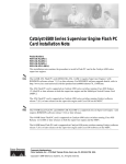
C H A P T E R
1
CompactFlash Disk, Flash Disk, and Flash
Memory Card Information
Product Numbers: MEM-I/O-FLC16M=, MEM-I/O-FLC20M=, MEM-I/O-FLD48M=, MEM-I/O-FLD64M=,
MEM-I/O-FLD128M=, MEM-7100-FLD48M=, MEM-7100-FLD128M=, MEM-NPE-G1-FLD64=, MEM-NPE-G1-FLD128=,
MEM-NPE-G1-FLD256=, MEM-NPE-G2-FLD256=
This chapter describes the CompactFlash Disk, Flash Disk, and Flash Memory card options and
specifications, as well as information regarding installation, reformatting, and copying bootable images.
The following topics are covered in this chapter:
•
Product Description, page 1-1
•
Boot Environment Variables, page 1-3
•
Installing and Removing a CompactFlash Disk, Flash Disk, or Flash Memory Card, page 1-4
•
Reformatting a CompactFlash Disk, Flash Disk, or Flash Memory Card, page 1-7
•
Copying a Bootable Image onto a CompactFlash Disk, Flash Disk, or Flash Memory Card, page 1-9
•
Copying Bootable Images Between Flash Disks or Flash Memory Cards, page 1-10
•
Working with a CompactFlash Disk, Flash Disk, or Flash Memory Card, page 1-11
Product Description
The CompactFlash Disk slots on the NPE-G1 and NPE-G2 network processing engines for the Cisco
7200 VXR routers, and the PC card slots on the I/O controllers and used with Cisco 7200 series routers,
use three types of Flash memory options. The PC card slots on the I/O controllers and CompactFlash
Disk slots on the NPE-G1 and Cisco uBR7200 series universal broadband routers also use three types of
Flash Memory options. These options as follows:
•
CompactFlash Disks. CompactFlash Disks are smaller in size than Flash Disks but provide the same
ATA interface and equivalent functionality.
Note
Use the CompactFlash Disk only with the NPE-G1 or NPE-G2 or UBR7200-NPE-G1. Do
not attempt to use a CompactFlash Disk in the Type 2 Flash Disk slots in an I/O controller.
Memory Replacement Instructions for the Network Processing Engine or Network Services Engine and Input/Output Controller
OL-8358-03
1-1
Chapter 1
CompactFlash Disk, Flash Disk, and Flash Memory Card Information
Product Description
•
Flash Disks, also known as Flash Memory Disks. Flash Disks are Flash memory-based devices that
conform to the PC card standard (formerly called Personal Computer Memory Card International
Association or PCMCIA) and present an ATA (AT Attachment) interface to the system. This
interface complies with the ANSI ATA Interface Document X3T13.1153 D Rev. 9 specification.
These cards provide from 48 MB to 256 MB of storage space.
The Flash Disk is more flexible than linear Flash memory because the Flash Disk has controller
circuitry that allows it to emulate a hard disk and automatically maps out bad blocks and performs
automatic block erasure. The Flash Disk also provides the capability to allocate noncontiguous
sectors, which eliminates the need for the squeeze command (which is required with linear Flash
memory cards to recover the space used by deleted files).
The Flash Disk also supports the Cisco IOS File System feature, which provides a single interface
to all of the router’s file systems, including the Flash Disks and onboard Flash memory, as well as
network file systems such as File Transfer Protocol (FTP) and Trivial FTP (TFTP) servers.
Note
•
The Flash Disk is only supported on systems with the Cisco IOS File System feature, and
the Cisco IOS File System feature is supported in Cisco IOS Release 12.0(1) or later releases
of 12.0. In general, Flash Disk functionality requires Cisco IOS Release 12.0(2) or a later
release of 12.0.
Linear Flash Disks, also known as PC cards, were the initial PC card used for the routers and are
available in 16 MB and 20 MB sizes.
Table 1-1 lists the CompactFlash Disk options and supported processors. Table 1-2 lists the Flash Disk
options and supported I/O controllers. Table 1-3 lists the PC card options and supported I/O controllers.
Table 1-1
Memory Size
64 MB
CompactFlash Disk Options
Product Number
Supported Processors
MEM-NPE-G1-FLD64
1
NPE-G1, UBR7200-NPE-G1
MEM-NPE-G1-FLD128
1
NPE-G1, UBR7200-NPE-G1
256 MB
MEM-NPE-G1-FLD256
1
NPE-G1, UBR7200-NPE-G1
256 MB
MEM-NPE-G2-FLD256
128 MB
NPE-G2
1. These products are also available as CompactFlash Disk upgrades. To order an upgrade, add an equal sign (=) after the
Product Number, for example, MEM-NPE-G1-FLD64=.
Table 1-2
Memory Size
Flash Disk Options
Product Number
Supported I/O Controllers
1
64 MB
MEM-I/O-FLD64M
128 MB
MEM-I/O-FLD128M,
C7200-I/O, C7200-I/O-FE, C7200-I/O-FE-MII,
MEM-7100-FLD128M1 C7200-I/O-2FE/E, C7200-I/O-GE-E+,
UBR7200-I/O, UBR7200-I/O/FE,
UBR7200-I/O-2FE/E
C7200-I/O, C7200-I/O-FE, C7200-I/O-FE-MII,
C7200-I/O-2FE/E, C7200-I/O-GE-E+,
UBR7200-I/O, UBR7200-I/O/FE,
UBR7200-I/O-2FE/E
1. These products are also available as Flash Disk upgrades. To order an upgrade, add an equal sign (=) after the Product
Number, for example, MEM-I/O-FLD64M=.
Memory Replacement Instructions for the Network Processing Engine or Network Services Engine and Input/Output Controller
1-2
OL-8358-03
Chapter 1
CompactFlash Disk, Flash Disk, and Flash Memory Card Information
Boot Environment Variables
Table 1-3
PC Card Options1
Memory Size
Product Number
Supported I/O Controllers
16 MB
MEM-I/O-FLC16M
C7200-I/O, C7200-I/O-FE, C7200-I/O-FE-MII,
UBR7200-I/O, UBR7200-I/O/FE
20 MB
MEM-I/O-FLC20M
C7200-I/O, C7200-I/O-FE, C7200-I/O-FE-MII,
UBR7200-I/O, UBR7200-I/O/FE
1. All linear PC card memory options have reached End-of-Life and are no longer orderable, but they can continue to be used
in existing legacy installations.
Note
A complete discussion of the Cisco IOS File System feature is beyond the scope of this publication. For
information about this feature, refer to the Configuration Fundamentals Configuration Guide and
Configuration Fundamentals Command Reference publications for Cisco IOS Release 12.x. These
publications are available on the Documentation DVD and on Cisco.com.
Boot Environment Variables
By default, and as a result of a reset or power on, the ROM monitor loads the boot image from boot flash
memory. If the ROM monitor cannot find a bootable image in boot flash memory, it searches the
CompactFlash Disk or PC card-based devices (such as linear Flash memory cards or Flash Disks) for the
first bootable image.
The boot image, when loaded, looks in the boot environment variables—stored in nonvolatile
random-access memory (NVRAM)—to determine the location of the Cisco IOS software image and the
configuration to use. If boot environment variables are not defined, the system will boot the first image
found on a Flash Disk, or if no such image is found, the system will boot the first image found on a linear
Flash memory card.
The contents of the boot environment variables, which are stored in the configuration file in NVRAM,
determine the actions your system takes on bootup. To see the current settings of these variables, use the
show bootvar command as follows:
Router> show bootvar
BOOT variable =
CONFIG_FILE variable =
Current CONFIG_FILE variable =
BOOTLDR variable does not exist
Configuration register is 0x100
Following are explanations for each of these boot environment variables:
•
BOOT variable—Points to the Cisco IOS software image that you want to boot; you set it in
configuration mode. The default software image is the CISCOxxx image (where xxx is a filename
assigned by the system, if you do not enter a specific filename). The system then looks for the first
image on the Flash Disk in slot 0.
Memory Replacement Instructions for the Network Processing Engine or Network Services Engine and Input/Output Controller
OL-8358-03
1-3
Chapter 1
Installing and Removing a CompactFlash Disk, Flash Disk, or Flash Memory Card
CompactFlash Disk, Flash Disk, and Flash Memory Card Information
Enter configuration mode and specify a filename and PC card slot from which to boot using the
configure terminal and boot system commands as follows:
Router# configure terminal
Enter configuration commands, one per line. End with CTRL-Z.
System(config)# boot system flash disk0:c7200-p-mz.12-0
The result of this configuration file entry is that the BOOT variable is disk0:c7200-p-mz.12-0.
•
CONFIG_FILE (configuration file) variable—Determines where the configuration is read from on
bootup; you set it in configuration mode as follows:
Router# configure terminal
Enter configuration commands, one per line. End with CTRL-Z.
System(config)# boot config disk0:configfile
The result of this configuration file entry is that the CONFIG_FILE variable is disk0:configfile.
•
BOOTLDR (boot loader) variable—Determines which image is used as the boot helper (boot
image); you set it in configuration mode as follows:
Router# configure terminal
Enter configuration commands, one per line. End with CTRL-Z.
System(config)# boot bootldr bootflash:c7200-boot-mz
The result of this configuration file entry is that the BOOTLDR variable is
bootflash:c7200-boot-mz.
•
Configuration register variable—Instructs the system where to look for a bootable Cisco IOS
software image; you set it as a hexadecimal value in configuration mode as follows:
Router# configure terminal
Enter configuration commands, one per line. End with CTRL-Z.
System(config)# config-register 0x102
The result of this configuration file entry is that the configuration register is set to hexadecimal
0x102. For more information about the configuration register, see Chapter 4, “Observing System
Startup and Performing a Basic Configuration,” in the Cisco 7200 VXR Installation and
Configuration Guide at the following URL:
http://www.cisco.com/en/US/products/hw/routers/ps341/products_installation_guide_book09186a
008007daa6.html.
Installing and Removing a CompactFlash Disk, Flash Disk, or
Flash Memory Card
This section describes the proper method for installing and removing a CompactFlash Disk, Flash Disk,
or Flash memory card into the CompactFlash Disk slots on an NPE-G1 or NPE-G2, or the Flask Disk or
PC card slots on an I/O controller.
Tip
All CompactFlash Disks, Flash Disks, and Flash memory cards must be formatted before their initial
use. CompactFlash Disks, Flash Disks, or Flash memory cards shipped with an I/O controller, NPE-G1,
or NPE-G2, are formatted at the factory, but spare memory cards are not formatted. To avoid potential
problems when using spare memory cards, we recommend that you reformat all of your memory cards
using the recommended minimum Cisco IOS software release for your platform during your regularly
scheduled service times. (See the “Software and Hardware Requirements” section on page 3-2.)
Memory Replacement Instructions for the Network Processing Engine or Network Services Engine and Input/Output Controller
1-4
OL-8358-03
Chapter 1
CompactFlash Disk, Flash Disk, and Flash Memory Card Information
Installing and Removing a CompactFlash Disk, Flash Disk, or Flash Memory Card
See the “Reformatting a CompactFlash Disk, Flash Disk, or Flash Memory Card” section on page 1-7
for instructions on how to reformat a memory card.
Note
For safety warnings for the memory cards, see the “Safety Guidelines” section on page 3-8.
An I/O controller has two physical PC card slots: slot 0 (lower) and slot 1 (upper). (See Figure 1-1.) The
NPE-G1 and NPE-G2 hve one CompactFlash Disk slot. (See Figure 1-2.)
Note
Do not confuse the physical card slot name with the proper device name to use when addressing the card.
Linear memory cards are addressed as the slot0: and slot1: devices. Flash Disk cards are inserted into
the slot0 and slot1 physical slots but are addressed as the disk0: and disk1: devices. The CompactFlash
Disk is inserted into the one slot on the NPE-G1 or NPE-G2 and is addressed as the disk2: device.
To install a Flash Disk or PC card in a PC card slot, complete the following steps.
Figure 1-1
Installing and Removing a PC Card or Flash Disk
a
SL
EN
AB
LE
D
EJ
EC
T
SL
OT
OT
1
0
b
SL
EN
AB
LE
D
EJ
EC
T
SL
OT
OT
1
0
c
SL
AB
LE
D
EC
EJ
T
SL
OT
1
0
H6437
EN
OT
Memory Replacement Instructions for the Network Processing Engine or Network Services Engine and Input/Output Controller
OL-8358-03
1-5
Chapter 1
Installing and Removing a CompactFlash Disk, Flash Disk, or Flash Memory Card
CompactFlash Disk, Flash Disk, and Flash Memory Card Information
Step 1
Attach an ESD wrist or ankle strap, connecting the equipment end of the strap to an unfinished chassis
surface.
Step 2
Orient the Flash Disk or PC card so that its connector end faces the appropriate slot. (See a in Figure 1-1
or 1 in Figure 1-2.)
Step 3
Carefully insert the card into the slot until it completely seats in the connector, and the ejector button for
the slot pops out toward you. (See b in Figure 1-1 or 2 in Figure 1-2.)
Tip
The Flash Disk is keyed and cannot be seated the wrong way. The ejector button does not pop out if the
Flash Disk is not completely inserted.
Note
PC cards do not insert all the way into the PC card slots on the I/O controller; the end of the card
protrudes from the I/O controller faceplate. Do not attempt to force the card past this point.
Some older PC cards might have foil tape attached to the outside edge of the card. If you insert
one of these PC cards into the upper PC card slot (slot 1) of an I/O controller installed in a
Cisco uBR7200 series router, it might be difficult to remove the card. You should use a new PC
card that does not have the foil tape, remove the foil tape from the older PC card, or if necessary,
use small pliers to remove the PC card.
This completes the procedure for installing a PC card in a PC card slot.
Figure 1-2
Installing and Removing a CompactFlash Disk
1
2
ORK PR
OCESSING
ENGINE
- G1
CT FLA
SH
ORK PR
OCESSING
ENGINE
- G1
C O M PA
CT FLA
SH
ORK PR
OCESSING
ENGINE
- G1
C O M PA
CT FLA
SH
66776
C O M PA
3
To remove and install a CompactFlash Disk from a CompactFlash Disk slot, complete the following
steps:
Step 1
Press the ejector button on the slot.
Step 2
Grasp the card and pull it from the slot.
Step 3
Place the card in an antistatic bag.
Step 4
Insert the CompactFlash Disk into the CompactFlash Disk slot until it engages. It protrudes slightly.
Memory Replacement Instructions for the Network Processing Engine or Network Services Engine and Input/Output Controller
1-6
OL-8358-03
Chapter 1
CompactFlash Disk, Flash Disk, and Flash Memory Card Information
Reformatting a CompactFlash Disk, Flash Disk, or Flash Memory Card
Reformatting a CompactFlash Disk, Flash Disk, or Flash Memory
Card
Depending on the circumstances, you might need to use a Compact Flash Disk, Flash Disk, or PC card
from another system to copy images or to back up configuration files; however, you cannot boot from a
CompactFlash Disk, Flash Disk, or PC card that was formatted on another type of system. You must
reformat the card before you can use it as a boot source.
The procedure for reformatting a CompactFlash Disk, Flash Disk, or PC card is similar. The major
difference between them is selecting the correct device name for formatting.
Note
To avoid potential problems when you insert CompactFlash Disks, Flash Disks, or PC cards in your
router, we recommend that you reformat all of your CompactFlash Disks, Flash Disks, or PC cards using
the recommended minimum Cisco IOS software release for your platform during your regularly
scheduled service times. (See the “Software and Hardware Requirements” section on page 3-2.)
Caution
The following formatting procedure erases all information on the CompactFlash Disk, Flash Disk, or PC
card. To prevent the loss of important data that might be stored on a CompactFlash Disk, Flash Disk, or
PC card, proceed carefully. If you want to save the data on a CompactFlash Disk, Flash Disk, or PC card,
copy the data to a server before you format the card.
The formatting procedure assumes the following:
•
You have already booted your Cisco 7200 series router or Cisco uBR7200 series router.
•
To be able to save the existing information on the CompactFlash Disk, Flash Disk, or PC card, you
should have access to a TFTP server (meaning you know its name and have connectivity to it), and
at least one interface is available over which you can access this server or a secondary CompactFlash
Disk, Flash Disk, or PC card.
Note
To ensure access to a TFTP server, you need to configure at least one network interface using
the setup facility. Refer to the Configuration Fundamentals Configuration Guide publication
for instructions on how to configure a network interface using the setup facility.
•
If you do not have access to a TFTP server and want to save the existing information on the
CompactFlash Disk, Flash Disk, or PC card, you have a second CompactFlash Disk, Flash Disk, or
PC card that is already formatted with sufficient space on which to copy the files.
•
You know the filename of the files you want to copy to the TFTP server or onto the secondary
CompactFlash Disk, Flash Disk, or PC card.
Use the following procedure to reformat a CompactFlash Disk, Flash Disk, or PC (Flash memory) card:
Step 1
Insert the disk or card into slot 0. (If slot 0 is not available, use slot 1.) See the “Installing and Removing
a CompactFlash Disk, Flash Disk, or Flash Memory Card” section on page 1-4.
Step 2
(Optional) Copy all the files on the CompactFlash Disk, Flash Disk, or PC card to a TFTP server or a
secondary Flash Disk or PC card using the copy command. The appropriate device name depends on the
type of memory card and the slot you are using. The CompactFlash Disk is inserted into the one slot on
Memory Replacement Instructions for the Network Processing Engine or Network Services Engine and Input/Output Controller
OL-8358-03
1-7
Chapter 1
CompactFlash Disk, Flash Disk, and Flash Memory Card Information
Reformatting a CompactFlash Disk, Flash Disk, or Flash Memory Card
the NPE-G1 or NPE-G2 and is addressed as the disk2: device. Flash Disks or PC cards are inserted into
the slot0 and slot1 physical slots but are addressed as the disk0: and disk1: devices. PC cards are
addressed as the slot0: and slot1: devices.
The following example is for copying files from a Flash Disk in physical slot0 (device name disk0:) to
a TFTP server:
Router> enable
Password: <password>
Router# copy disk0:image.name tftp
Enter destination file name [image.name]: image.name
CCCCCCCCCCCCCCCCCCCCCCCCCCCCCCCCCCCCCCCCCCCCCCCCCCCCCCCCCCCCCCCCCCCCCCCCCCCCCCCCCCCCCCCCCC
CCCCCCCCCCCC
Address or name of remote host [tftp.server.name]? tftp.server.name
!!!!!!!!!!!!!!!!!!!!!!!!!!!!!!!!!!!!!!!!!!!!!!!!!!!!!!!!!!!!!!!!!!!!!!!!!!!!!!!!!!!!!!!!!!
!!!!!!!!!!
Step 3
To reformat the CompactFlash Disk, Flash Disk, or PC card, use the format command along with the
appropriate device name. The following example shows a Flash Disk in slot0 being formatted:
Router# format disk0:
All sectors will be erased, proceed? [confirm]
Enter volume id (up to 30 characters): MyNewCard
Formatting sector 1
Format device slot1 completed
Router#
Step 4
(Optional) Copy the files you saved to the TFTP server or second card or Flash disk back to the
CompactFlash Disk, Flash Disk, or PC card as follows:
Router# copy tftp disk0:
Enter source filename: image.name
20575008 bytes available on device disk0, proceed? [confirm]
address or name of remote host [tftp.server.name]? tftp.server.name
loading new.image from tftp.server.name (via Ethernet1/0):!!!!!!!
!!!!!!!!!!!!!!!!!!!!!!!!!!!!!!!!!!!!!!!!!!!!!!!!!!!!!!!!!!!!!!!!!!!!!!!!!!!!!!!!!!!!!!!!!!
!!!!!!!!!!!!!!!!!!!!!!!!!!!!!!!!!!!!!!!!!!!!!!!!!!!!!!!!!!!!!!!!!!!!!!!!!!!!!!!!!!!!!!!!!!
!!!!!!!!!!!!!!!!!!!!!!!!!!!!!!!!!!!!!!!!!!!!!!!!!!!!!!!!!!!!!!!!!!!!!!!!!!!!!!!!!!!!!!!!!!
!!!!!!!!!!!!!!!!!!!!!!!!!!!!!!!!!!!!!!!!!!!!!!!!!!!!!!!!!!!!!!!!!!!!!!!!!!!!!!!!!!!!!!!!!!
!!!!!!!!!!!!!!!!!!!!!!!!!!!!!!!!!!!!!!!!!!!!!!!!!!!!!!!!!!!!!!!!!!!!!!!!!!!!!!!!!!!!!!!!!!
!!!!!!!!!!!!!!!!!!!!!!!!!!!!!!!!!!!!!!!!!!!!!!!!!!!!!!!!!!!!!!!!!!!!!!!!!!!!!!!!!!!!!!!!!!
!!!!!!!!!!!!!!!!!!!!!!!!!!!!!!!!!!!!!!!!!!!!!!!!!!!!!!!!!!!!!!!!!!!!!!!!!!!!!!!!!!!!!!!!!!
!!!!!!!!!!
[OK - 7799951/15599616 bytes]
CCCCCCCCCCCCCCCCCCCCCCCCCCCCCCCCCCCCCCCCCCCCCCCCCCCCCCCCCCCCCCCCCCCCCCCCCCCCCCCCCCCCCCCCCC
CCCCCCCCCCCCCCCCCCCCCCCCCCCCCCCCCCCCCCCCCCCCCCCCCCCCCCCCCCCCCCCCCCCCCCCCCCCCCCCCCCCCCCCCCC
CCCC
Router#
The CompactFlash Disk, Flash Disk, or PC card is now reformatted and ready to use.
Memory Replacement Instructions for the Network Processing Engine or Network Services Engine and Input/Output Controller
1-8
OL-8358-03
Chapter 1
CompactFlash Disk, Flash Disk, and Flash Memory Card Information
Copying a Bootable Image onto a CompactFlash Disk, Flash Disk, or Flash Memory Card
Copying a Bootable Image onto a CompactFlash Disk, Flash
Disk, or Flash Memory Card
After you have reformatted your CompactFlash Disk, Flash Disk, or PC (Flash memory) card, you can
copy a bootable image onto it. The procedure for copying an image onto a CompactFlash Disk, Flash
Disk, or PC card is based on the following assumptions:
•
You have an I/O controller or NPE-G1 or NPE-G2 with a good image in the onboard Flash memory
so you can start the router.
•
The bootable image you want to copy to the Compact Flash Disk, Flash Disk, or PC card exists on
a TFTP server to which you have access (meaning you know its name and have connectivity to it),
and at least one interface is available over which you can access this server.
Note
•
To ensure access to a TFTP sever, you will need to configure at least one network interface
using the setup facility. Refer to the Configuration Fundamentals Configuration Guide
publication for instructions on how to configure a network interface using the setup facility.
You know the filename of the image you want to copy onto the CompactFlash Disk, Flash Disk, or
PC card.
Use the following procedure to copy a bootable file (called new.image in the examples) to the memory
card:
Step 1
Boot the router and allow it to initialize.
Step 2
Insert a CompactFlash Disk, Flash Disk, or PC card into an available slot and reformat the disk or card
using the procedure in the “Reformatting a CompactFlash Disk, Flash Disk, or Flash Memory Card”
section on page 1-7. Then proceed to Step 3.
Note
Step 3
You cannot boot from a CompactFlash Disk, Flash Disk, or PC card that was formatted on
another type of system. You must reformat the disk or card to use it as a boot source. To avoid
potential problems when you insert a CompactFlash Disk, Flash Disk, or PC card in your router,
we recommend that you reformat all of your CompactFlash Disks, Flash Disks, or PC cards
using the recommended minimum Cisco IOS software release for your platform during your
regularly scheduled service times. (See the “Software and Hardware Requirements” section on
page 3-2, and Table 1-1, Table 1-2, and Table 1-3 in this chapter.)
Use the following series of commands to copy the new image (new.image in the following example) to
a PC card in slot0:
Router> enable
Password:
Router# copy tftp:new.image slot0:new.image
20575008 bytes available on device slot0, proceed? [confirm]
address or name of remote host [1.1.1.1]?
loading new.image from 1.1.1.1 (via Ethernet1/0):!!!!!!!!!!!!!!!!!!
!!!!!!!!!!!!!!!!!!!!!!!!!!!!!!!!!!!!!!!!!!!!!!!!!!!!!!!!!!!!!!!!!!!!!!!!!!!!!!!!!!!!!!!!!!
!!!!!!!!!!!!!!!!!!!!!!!!!!!!!!!!!!!!!!!!!!!!!!!!!!!!!!!!!!!!!!!!!!!!!!!!!!!!!!!!!!!!!!!!!!
!!!!!!!!!!!!!!!!!!!!!!!!!!!!!!!!!!!!!!!!!!!!!!!!!!!!!!!!!!!!!!!!!!!!!!!!!!!!!!!!!!!!!!!!!!
!!!!!!!!!!!!!!!!!!!!!!!!!!!!!!!!!!!!!!!!!!!!!!!!!!!!!!!!!!!!!!!!!!!!!!!!!!!!!!!!!!!!!!!!!!
!!!!!!!!!!!!!!!!!!!!!!!!!!!!!!!!!!!!!!!!!!!!!!!!!!!!!!!!!!!!!!!!!!!!!!!!!!!!!!!!!!!!!!!!!!
!!!!!!!!!!!!!!!!!!!!!!!!!!!!!!!!!!!!!!!!!!!!!!!!!!!!!!!!!!!!!!!!!!!!!!!!!!!!!!!!!!!!!!!!!!
!!!!!!!!!!!!!!!!!!!!!!!!!!!!!!!!!!!!!!!!!!!!!!!!!!!!!!!!!!!!!!!!!!!!!!!!!!!!!!!!!!
Memory Replacement Instructions for the Network Processing Engine or Network Services Engine and Input/Output Controller
OL-8358-03
1-9
Chapter 1
CompactFlash Disk, Flash Disk, and Flash Memory Card Information
Copying Bootable Images Between Flash Disks or Flash Memory Cards
[OK - 7799951/15599616 bytes]
CCCCCCCCCCCCCCCCCCCCCCCCCCCCCCCCCCCCCCCCCCCCCCCCCCCCCCCCCCCCCCCCCCCCCCCCCCCCCCCCCCCCCCCCCC
CCCCCCCCCCCCCCCCCCCCCCCCCCCCCCCCCCCCCCCCCCCCCCCCCCCCCCCCCCCCCCCCCCCCCCCCCCCCCCCCCCCCCCCCCC
CCCC
Router#
Note
Step 4
In the preceding example, the exclamation points (!!!) appear as the file is downloaded, and the
“C” characters signify calculation of the checksum, which is a verification that the file has been
correctly downloaded to the PC card.
Use the following series of commands to designate the new.image file (in slot 0) as the default boot
helper image and reboot the router:
Router# configure terminal
Router(config)# no boot system
Router(config)# boot system flash slot0:new.image
Router(config)# Ctrl-Z
Router# copy running-config startup-config
Router# reload
Insert the Compact Flash Disk, Flash Disk, or PC card into the default boot device for your router
(typically, this is slot0 for an I/O controller or the CompactFlash Disk slot for the NPE-G1 or NPE-G2).
When the system reloads, it will boot the new.image file from the memory card or disk.
Copying Bootable Images Between Flash Disks or Flash
Memory Cards
As future releases of Cisco IOS images become available, you will receive these images either as a file
booted from a network server, a file on floppy disk, or a file on a Flash Disk or PC Card. Use the
following procedure for copying bootable images between disks or cards so that you can use the new
software image in your router.
The following scenario describes how to use a newly released image on a Flash Disk or PC card in a
system that has an older image on a Flash Disk, or PC card in the slot 0, and a default boot helper image
in the onboard Flash memory.
For this scenario, the filenames are as follows:
•
The new image on the new Flash Disk or PC card is new.image.
•
The old image on the Flash Disk or PC card in slot 0 is old.image.
•
The bootable image in onboard Flash memory is boot.image.
You will copy the new image from the new Flash Disk or PC card onto the Flash Disk or PC card that
contains the old image.
Note
The scenario assumes that the new image will fit on the Flash Disk or PC card in slot 0, alongside the
old image. If there is not enough available space, use the delete command to delete files from the card
to make sufficient room for the new image; however, do not delete the old.image file. If you are using a
Flash Disk or PC card, you must then use the squeeze command to make the deleted space available for
new files. If, after you have deleted files and used the squeeze command, the two files cannot coexist on
Memory Replacement Instructions for the Network Processing Engine or Network Services Engine and Input/Output Controller
1-10
OL-8358-03
Chapter 1
CompactFlash Disk, Flash Disk, and Flash Memory Card Information
Working with a CompactFlash Disk, Flash Disk, or Flash Memory Card
the PC card in slot 0, remove this card (place it in an antistatic bag and store it in a safe place), and insert
the new PC card (with the new.image file) in slot 0. Proceed to Step 5 and use the boot system flash
slot0:new.image command to designate the new.image file as the default boot helper image.
Step 1
Boot the router. By default, the boot.image file is used.
Step 2
Enable the router as follows:
Router> enable
Password:
Router#
Step 3
Insert the new Flash Disk or PC card in slot 1.
Step 4
Use the following command to copy the new.image file in slot 1 to the Flash Disk or PC card in slot 0,
only if there is enough memory space for the two images to coexist. If there is not enough memory space,
proceed to Step 5.
Router# copy slot1:new.image slot0:new.image
Note
Step 5
Use the disk0: and disk1: device names when using Flash Disks.
Use the following series of commands to designate the new.image file (which is on the card in slot 0) as
the default boot helper image and reboot the router:
Router# configure terminal
Router(config)# no boot system
Router(config)# boot system flash slot0:new.image
Router(config)# Ctrl-Z
Router# copy running-config startup-config
Router# reload
When the system reloads, it will boot the new.image file from the card in slot 0.
Working with a CompactFlash Disk, Flash Disk, or Flash
Memory Card
This section provides basic instructions for working with a CompactFlash Disk, Flash Disk, or Flash
memory card in your system. Detailed descriptions of more complex CompactFlash Disk, Flash Disk, or
Flash memory card options and the Cisco IOS File System feature are beyond the scope of this
publication and can be found in the following Cisco IOS Release 12.x publications:
•
Configuration Fundamentals Configuration Guide, in the chapter “File Management”
•
Configuration Fundamentals Command Reference, in the chapter “File Management Commands”
Software Command Overview
This section lists some of the basic software commands you can use with a CompactFlash Disk, Flash
Disk, or PC card. Examples of these commands are included in the sections that follow.
Memory Replacement Instructions for the Network Processing Engine or Network Services Engine and Input/Output Controller
OL-8358-03
1-11
Chapter 1
CompactFlash Disk, Flash Disk, and Flash Memory Card Information
Working with a CompactFlash Disk, Flash Disk, or Flash Memory Card
The CompactFlash Disk, Flash Disk, or Flash memory cards, along with other locations in your system,
are defined as file systems, which are locations where you can store, use, or retrieve files and software
images. You can use a Flash Disk or Flash memory card in either one or both of the PC card slots in your
I/O controller, and you can use a CompactFlash Disk in the one CompactFlash Disk slot on the NPE-G1
or NPE-G2.
The CompactFlash Disk inserted into the CompactFlash Disk slot in the NPE-G1 or NPE-G2 is referred
to as the disk2: device. Flash Disks or PC cards inserted into slot0 and slot1 are referred to as the slot0:
and slot1: devices, respectively.
The following partial output of the show file systems command shows a sample system with a
Flash Disk—called disk0:—installed in PC card slot 0 and a linear Flash memory card—called
slot1:—installed in PC card slot 1:
Router# show file systems
File Systems:
Size(b)
32768000
7995392
48755200
522232
-
Note
Free(b)
29093816
4717276
48747008
505412
-
Type
flash
flash
flash
flash
disk
opaque
opaque
network
nvram
network
network
Flags
rw
rw
rw
rw
rw
rw
rw
rw
rw
rw
rw
Prefixes
bootflash:
slot0: flash:
slot1:
disk0:
disk1:
system:
null:
tftp:
nvram:
rcp:
ftp:
The show file systems command displays all recognized file systems, even if they are not currently in
use. This is why the above display shows entries for both slot0: and disk1:, even though those devices
are not currently inserted into the PC card slots.
Table 1-4 lists the software commands, along with their most common command options, that you can
use with the Flash memory cards.
The following device names can be used with most of these commands:
•
disk2: (CompactFlash Disk)
•
disk0: and disk1: (Flash Disks)
•
slot0: and slot1: (linear PC cards)
•
bootflash: (onboard Flash memory)
•
nvram: (onboard nonvolatile random-access memory)
•
running-config (the running system configuration file)
•
startup-config (the startup system configuration file)
•
tftp: (a TFTP server to which you have access)
Memory Replacement Instructions for the Network Processing Engine or Network Services Engine and Input/Output Controller
1-12
OL-8358-03
Chapter 1
CompactFlash Disk, Flash Disk, and Flash Memory Card Information
Working with a CompactFlash Disk, Flash Disk, or Flash Memory Card
Table 1-4
Flash Disk-Related Software Commands
Command and Arguments
cd [dev:]directory-name
Purpose
1
Changes current directory.
Allows you to move between directories on a file system, where
directory-name is the directory to which you want to move.
copy [dev:]source-filename
[dev:]destination-filename
Copies from one file to another.
Allows you to make a copy of a file (source-filename) located on a
source file system (dev:) and place it with either the same filename
or a different filename (destination-filename) on a destination file
system.
delete [dev:]filename
Deletes a file.
Allows you to delete any file you designate, where filename
designates the name of the file.
dir [/all | dev:]
Lists files on a file system.
Allows you to list the contents of the Flash Disks in PC Card slots
0 and 1. The /all argument lists all files on all file systems in your
system.
format [flash: | bootflash: | dev:]
Formats a file system.
Allows you to format a linear Flash memory card (flash:), onboard
Flash memory (bootflash:), Flash Disk (disk0: or disk1:), or
Compact Flash Disk (disk2:). This command also allows you to
reformat a linear Flash memory card or Flash Disk that was
formatted on another type of system.
Note
This command destroys all data currently in Flash memory;
therefore, we strongly recommend that you use the format
command with caution to prevent irretrievable loss of data.
mkdir [dev:]directory-name1
Creates a new directory.
Allows you to create directories on a Flash Disk, where
directory-name is the name you assign to this directory.
pwd1
Displays current working directory.
Allows you to display the name of the Flash Disk directory in which
you are currently working.
rename [dev:]filename
[dev:]filename
Renames a file.
Allows you to rename a file that is located on one Flash Disk and
assign to that file another (or the same) file system path and
filename. The first group of arguments defines the source (current)
file system path and filename, and the second set of arguments
defines the destination file system path and filename.
rmdir [dev:]directory-name1
Removes an existing directory.
Allows you to remove a directory that currently exists on a Flash
Disk, where directory-name is the name of the directory you want
to remove.
show [dev:]
Lists information about Flash Disk format and geometry.
show file systems
Displays a list of all defined file systems.
1. This command does not work with a PC Card.
Memory Replacement Instructions for the Network Processing Engine or Network Services Engine and Input/Output Controller
OL-8358-03
1-13
Chapter 1
CompactFlash Disk, Flash Disk, and Flash Memory Card Information
Working with a CompactFlash Disk, Flash Disk, or Flash Memory Card
Tip
For complete command information, see the “File Management Commands” chapter in the
Configuration Fundamentals Command Reference document.
Using Software Commands
This section provides examples of some of the basic software commands you can use with the
CompactFlash Disk, Flash Disk, or Flash memory cards.
•
Using the show Command, page 1-14
•
Using the pwd Command, page 1-15
•
Using the cd Command, page 1-15
•
Using the dir Command, page 1-15
•
Using the format Command, page 1-16
•
Using the copy Command, page 1-17
•
Using the mkdir Command, page 1-18
•
Using the rmdir Command, page 1-18
•
Using the delete Command, page 1-18
Using the show Command
To display information about the CompactFlash Disk, Flash Disk, or Flash memory card format and
geometry, use the show [dev:] command:
System# show disk0:
******** ATA Flash Card Geometry/Format Info ********
ATA CARD GEOMETRY
Number of Heads:
Number of Cylinders
Sectors per Cylinder
Sector Size
Total Sectors
16
840
32
512
430080
ATA CARD FORMAT
Number of FAT Sectors
Sectors Per Cluster
Number of Clusters
Number of Data Sectors
Base Root Sector
Base FAT Sector
Base Data Sector
105
16
26822
429536
338
128
370
Router#
In this example:
•
Number of Heads is the number of heads on the Flash Disk.
•
Number of Cylinders is the number of cylinders on the Flash Disk.
•
Sectors per Cylinder is the number of sectors in each cylinder.
•
Sector Size is the number of bytes in each sector.
Memory Replacement Instructions for the Network Processing Engine or Network Services Engine and Input/Output Controller
1-14
OL-8358-03
Chapter 1
CompactFlash Disk, Flash Disk, and Flash Memory Card Information
Working with a CompactFlash Disk, Flash Disk, or Flash Memory Card
•
Total Sectors is the total number of sectors on the Flash Disk.
•
Number of FAT Sectors is the number of sectors used to track allocation of clusters to files.
•
Sectors Per Cluster is the number of sectors contained in each cluster. (Files grow by a minimum of
one cluster.)
•
Number of Clusters is the total number of clusters available for use by files.
•
Number of Data Sectors is the number of sectors available for files.
•
Base Root Sector is the logical address of the first sector of the root directory.
•
Base FAT Sector is the first sector in the File Allocation Table (FAT).
•
Base Data Sector is the first sector available for use by files.
Using the pwd Command
To determine which CompactFlash Disk or Flash Disk slot you are accessing, use the pwd command:
System# pwd
disk0:/
System#
The preceding example indicates that you are currently in the working directory called disk0:, which is
the Flash Disk in PC Card slot 0.
Using the cd Command
To move back and forth between installed Flash Disks, use the cd command by defining a specific path
name. Then to verify your working directory, use the pwd command:
System#
System#
disk1:/
System#
System#
disk0:/
cd disk1:
pwd
cd disk0:
pwd
You can also move up (or back) one level in the directory hierarchy using the cd .. command, and then
verify your working directory with the pwd command:
System# pwd
disk1:daily_dir/
System# cd ..
System# pwd
disk1:/
System#
Using the dir Command
To list the directory structure and contents of the CompactFlash Disk, Flash Disk, or PC card from which
you are currently working, use the dir command with no arguments:
System# dir
Directory of disk1:/
1 drw2 drw-
0
0
Jul 25 1998 10:23:11
Jul 25 1998 10:28:37
daily_dir
access_lists
48755200 bytes total (48742912 bytes free)
Memory Replacement Instructions for the Network Processing Engine or Network Services Engine and Input/Output Controller
OL-8358-03
1-15
Chapter 1
CompactFlash Disk, Flash Disk, and Flash Memory Card Information
Working with a CompactFlash Disk, Flash Disk, or Flash Memory Card
System#
Note that the size of the CompactFlash Disk, Flash Disk, or PC card is shown in the output of the dir
command. (A 48-MB Flash Disk is shown in this example.) You can also view the contents of other
directories and file systems using specific optional arguments with the dir command. (See Table 1-4.)
Using the format Command
To format a new CompactFlash Disk, Flash Disk, or PC card, use the format [dev:] command.
Note
You must format a new CompactFlash Disk, Flash Disk, or PC card before you can use it. Flash memory
cards or Flash Disks shipped with I/O controllers or CompactFlash Disks shipped with the the NPE-G1
or NPE-G2 are formatted at the factory. Spare Flash memory cards are blank and must be formatted
before you can use them.
Caution
The formatting procedure erases all information on the Flash Disk. To prevent the loss of important data
that might be stored on a Flash Disk, proceed carefully. If you want to save data that is currently on your
Flash Disk, copy the data to a TFTP server or to another Flash Disk before you format the new Flash
Disk. A Flash Disk that was shipped as part of a configured system contains a Flash Disk-compatible
Cisco IOS software image; therefore, you do not need to format it to use it in the system in which it was
shipped.
Use the following procedure to format a new CompactFlash Disk, Flash Disk, or PC card using the
format command. (The procedure assumes you have already booted your system.)
Step 1
Insert the Flash memory card into the appropriate PC card slot.
Step 2
Use the format dev: command to format the CompactFlash Disk, Flash Disk, or PC card. Use the
disk2:device name for a CompactFlash Disk, disk0: and disk1: device names for Flash Disks, and slot0:
and slot1: device names for linear PC cards. The following example shows a 48–MB Flash Disk in slot0
being formatted:
System# format disk0:
Format operation may take a while. Continue? [confirm]
Format operation will destroy all data in ‘disk0:’. Continue? [confirm]
Format:Drive communication & 1st Sector Write OK...
Writing Monlib
sectors.....................................................................
.......................
Monlib write complete
Format:All system sectors written. OK...
Format:Total sectors in formatted partition:81760
Format:Total bytes in formatted partition:49861120
Format:Operation completed successfully.
Format of disk0:complete
The new CompactFlash Disk, Flash Disk, or PC card is now formatted and ready to use in the system on
which you formatted it.
Memory Replacement Instructions for the Network Processing Engine or Network Services Engine and Input/Output Controller
1-16
OL-8358-03
Chapter 1
CompactFlash Disk, Flash Disk, and Flash Memory Card Information
Working with a CompactFlash Disk, Flash Disk, or Flash Memory Card
Using the copy Command
To copy an image from a CompactFlash Disk, Flash Disk, or PC card to another file system or from
another file system to the Flash Disk, use the copy command:
copy [dev:]source-filename [dev:]destination-filename
In this example:
•
The file you want to copy is located in a file system (tftp:, bootflash:, slot0:, disk1:, and so forth).
•
The variable source-filename is the name of the file you want to copy to another file system (tftp:,
bootflash:, slot0:, disk1:, and so forth).
•
The variable destination-filename is the name you want to apply to this file after it is copied. This
can be the same name as the original filename or a different filename.
The following assumptions are made for this command:
•
You have a system processor with a Flash Disk-compatible Cisco IOS software image in the onboard
Flash memory—called boot flash memory—so you can start the system.
•
Your system is running Cisco IOS Release 12.0(2) or later.
•
The bootable image you want to copy to the CompactFlash Disk, Flash Disk, or PC card exists in
another file system or on a TFTP server to which you have access (meaning you know its name and
have connectivity to it), and at least one interface is available over which you can access this server
through Telnet. To ensure access to a TFTP server, you need to configure at least one interface. To
configure an interface, you can use the setup command or use the configuration editor.
An Ethernet interface is used in the examples that follow.
•
Note
You know the filename of the image you want to copy to the CompactFlash Disk, Flash Disk, or PC
card.
You might need to copy a new image to a CompactFlash Disk, Flash Disk, or PC Card whenever a new
Cisco IOS software release or a new Cisco IOS software maintenance release becomes available. You
can use the copy command for this purpose.
Use the following procedure to copy a file (called new.image in this example) located on a
Flash Disk—called disk1:—in PC card slot 1 to the Flash Disk—called disk0:—in PC card slot 0:
Step 1
If the CompactFlash Disk, Flash Disk, or PC card is unformatted or has been formatted on another,
possibly incompatible system, format it now using the procedure in the “Using the format Command”
section on page 1-16, as appropriate.
Step 2
To copy the image new.image to Flash Disk disk0:, use the following series of commands:
System> enable
Password:
System# copy disk1:new.image disk0:new.image
3393 bytes copied in 0.548 secs#
System#
In the preceding example, the 3393-byte file new.image was copied to the Flash Disk in PC card slot 0
in approximately one-half second.
Memory Replacement Instructions for the Network Processing Engine or Network Services Engine and Input/Output Controller
OL-8358-03
1-17
Chapter 1
CompactFlash Disk, Flash Disk, and Flash Memory Card Information
Working with a CompactFlash Disk, Flash Disk, or Flash Memory Card
Step 3
Verify that the file new.image is now on the Flash Disk in PC card slot 0:
System# pwd
disk0:/
System# dir
Directory of disk0:/
1
-rw-
3393
Jul 26 1998 17:44:47 new.image
48755200 bytes total (48747008 bytes free)
Using the mkdir Command
To create a directory on a CompactFlash Disk or Flash Disk, use the mkdir command. The following
example shows how to create a directory called daily_dir on the Flash Disk in PC card slot 1, and then
verify that it was created:
System# mkdir disk1:daily_dir
Created dir disk1:daily_dir
System# dir
Directory of disk1:/
1
drw-
0
Jul 25 1998 10:15:43
daily_dir
48755200 bytes total (48751104 bytes free)
Note
If you create a directory and place a file in it that you plan to access or use later on, be sure to define the
entire directory path to the file as you enter the appropriate software commands.
For example, if you placed the file itsa.file into the directory daily_dir on a Flash Disk in slot 1, you
must designate the entire directory path as follows: disk1:daily_dir/itsa.file. Otherwise, the system
might not be able to locate this file.
Using the rmdir Command
To remove a directory from a CompactFlash Disk or Flash Disk, use the rmdir command. The following
example shows how to remove the directory daily_dir from the Flash Disk in PC Card slot 1, and then
verify that it was removed:
System# rmdir disk1:daily_dir
Delete disk1:daily_dir? [confirm] y
Removed dir disk1:daily_dir
System# dir
Directory of disk1:/
No files in directory.
48755200 bytes total (48751104 bytes free)
Using the delete Command
To delete a file from a CompactFlash Disk, Flash Disk, or PC card, use the delete command. Use the dir
command to find the file you want to delete, and then use the delete command to delete it.
Memory Replacement Instructions for the Network Processing Engine or Network Services Engine and Input/Output Controller
1-18
OL-8358-03
Chapter 1
CompactFlash Disk, Flash Disk, and Flash Memory Card Information
Working with a CompactFlash Disk, Flash Disk, or Flash Memory Card
The following example shows how to find a file (called fun1) on the Flash Disk in PC card slot 0, delete
the file, and then verify that it is deleted:
Step 1
Find the file you want to delete:
System# dir
Directory of disk0:/
1
drw-
0
May 10 1998 09:54:53 fun1
48755200 bytes total (48742912 bytes free)
Step 2
Delete the file fun1:
System# delete disk0:fun1
Step 3
Verify that the file fun1 is deleted:
System# dir
Directory of disk0:/
No files in directory.
48755200 bytes total (48742912 bytes free)
System#
Enabling Booting from a CompactFlash Disk, Flash Disk, or PC Card
To enable booting from a Flash memory card, set configuration register bits 3, 2, 1, and 0 to a value
between 2 and 15 in conjunction with the boot system [dev:]filename configuration command. The
following are definitions of the various Flash Disk-related boot commands:
Note
•
boot system flash disk0: or boot system slot0:—Boots the first file on the card in slot 0.
•
boot system flash disk1: or boot system slot1:—Boots the first file on the card in slot 1.
•
boot system flash disk0:herfile or boot system slot0:herfile—Boots the file named herfile on the
card in slot 0.
•
boot system flash disk1:hisfile or boot system slot1:hisfile—Boots the file named hisfile on the
card in slot 1.
As you enter boot commands, pay attention to how you use the Spacebar, which influences the way your
system interprets the commands. Also, ensure that you define the entire path to a file as you enter the
boot commands; otherwise, the system might not be able to find the file.
For example, notice the difference in the following correct and incorrect commands:
System(config)# boot flash system disk0:myfile
Based on the preceding correct command, the system boots the file specified (myfile).
System(config)# boot flash system disk0: myfile
Based on the preceding incorrect command, the system finds the filename field blank because there is a
space after the disk0: name. In this case, the system ignores the filename argument and boots the first
file on the Flash Disk, which might not be the file called myfile.
Memory Replacement Instructions for the Network Processing Engine or Network Services Engine and Input/Output Controller
OL-8358-03
1-19
Chapter 1
CompactFlash Disk, Flash Disk, and Flash Memory Card Information
Working with a CompactFlash Disk, Flash Disk, or Flash Memory Card
Use the following procedure to enable booting the file myfile from a Flash memory card:
Step 1
Enter configuration mode and specify an image filename in the PC card slot from which to boot by using
the configure terminal command, as follows:
System# configure terminal
Enter configuration commands, one per line. End with CTRL-Z.
System(config)# boot system flash disk0:myfile
Note
Step 2
Specify disk2: for a CompactFlash Disk on the NPE-G1 or NPE-G2.
Enable the boot system flash disk0:myfile command using the config-register command with the
hexadecimal value shown in the following example:
System(config)# config-reg 0x2102
This command, with the hexadecimal value 0x2102, results in the following:
Step 3
•
Enables the system to boot the default boot ROM software if the Flash Disk-based image fails to
boot—hexadecimal value 0x2000
•
Disables Break—hexadecimal value 0x0100
•
Enables the image myfile as the default boot image—hexadecimal value 0x0002
Press Ctrl-Z to exit configuration mode:
System(config)#
Crtl-Z
System#
Step 4
Save the new configuration to NVRAM by using the copy system:running-config
nvram:startup-config command as follows:
System# copy system:running-config nvram:startup-config
Making a CompactFlash Disk or Flash Disk-Based Software Image the
Bootable Software Image
After you copy a software image to the Flash Disk, use the following series of commands to make the
image bootable (the file named new.image in this example). The software image in this example is
located on the Flash Disk in PC card slot 0. Note that the config-register command is also a part of this
command sequence because you must set the configuration register to 0x2102 to enable loading an image
from the Flash Disk.
System# config terminal
System(config)# no boot system
System(config)# boot system flash disk0:new.image
System(config)# config-register 0x2102
Ctrl-Z
System# copy system:running-config nvram:startup-config
System# reload
When the system reloads, it boots the image new.image from the Flash Disk in slot 0.
Memory Replacement Instructions for the Network Processing Engine or Network Services Engine and Input/Output Controller
1-20
OL-8358-03