1
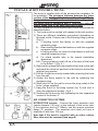
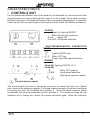
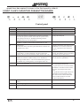
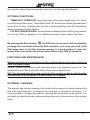
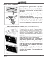
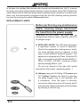
Instruction booklet
Libretto di lstruzioni (IT)
Instruction booklet (EN)
(AR)
Mode d’emploi (FR)
Bedienungsanleitung (DE)
Instruktionsvejledning (DA)
Manual de instrucciones (ES)
Instrukcja (PL)
Manual de lnstruções (PT)
Instructiehandleiding (NL)
Bruksanvisning (NO)
Руководство по эксплуатации (RU)
Instruktionshandbo (SV)
WARNINGS!
INSTALLATION
• Read the instructions closely before installing and/or using the
hood.
• The manufacturer will not be held liable for damage caused by installation
that is incorrect or not up to standard.
• We recommend that all installation and adjustment procedures are
carried out by trained personnel.
• When the hood is taken out of its packaging inspect it to ensure that it
is intact. If the product is damaged, do not use it and contact the Smeg
assistance service.
• Before making any connections, make sure that the mains voltage
corresponds to the voltage shown on the label located inside the
appliance.
• For Class I appliances, check that the domestic power supply guarantees
adequate earthing.
• The minimum distance between the hob and the lower part of the hood
must be at least 750mm for gas hobs and 650mm for electric hobs.
• The extracted air must not be conveyed in a duct used to conduct fumes
from appliances powered by gas.
• Connect the outlet for the air extracted by the hood to fumes discharge
ducts with a suitable internal diameter, and no less than 120 mm.
• The room must be adequately ventilated when the hood or gas appliances
are used simultaneously.
• If the power cable is damaged it must be replaced by the manufacturer
or its technical assistance service, or nonetheless by an individual with
a similar qualification, so as to prevent any risk.
• Comply with any legal regulations relative to the extraction of air when
operating the extraction hood.
OPERATION
• Do not cook or fry in a way that creates strong flames. These could be
drawn into the hood during operation and cause a fire.
• Do not flambé food under the kitchen hood; Fire hazard
• The hood can be used by individuals under the age of 8 and by individuals
with physical, sensorial or mental impairments, or without experience or
the required knowledge, as long as they are under supervision or have
EN
1
been given instructions on safe use of the appliance and are familiar
with the dangers it entails.
• Children must be supervised to ensure that they do not play with the
appliance
• “ATTENTION: The accessible parts can become very hot if they are
used with cooking equipment."
MAINTENANCE
• Before carrying out any maintenance procedure or cleaning, disconnect
the appliance from the electricity supply.
• Carry out thorough and timely maintenance of the filters in accordance
with the intervals recommended by the manufacturer.
• To clean the hood surfaces, use a damp cloth and a mild liquid
detergent.
• Cleaning and maintenance carried out by the user must not be performed
by children without supervision;
• THE MANUFACTURER DECLINES ALL RESPONSIBILITY IF THE
ABOVE INDICATIONS ARE NOT FOLLOWED
USE:
• This appliance was designed to be used as an EXTRACTION (extraction
of air to the outside) or FILTER hood (recirculation of air indoors).
• EXTRACTION VERSION: To turn the hood into the extraction version
connect the motor inlet, by means of a rigid or flexible pipe with a suitable
internal diameter and no less than 120 mm, directly to the external vapour
and odour extraction duct.
NB. Remove any active carbon odour-control filters.
• FILTER VERSION: If it is not possible to direct the air outdoors, the
hood can be transformed into the filter version. In this version, the air
and vapours are purified by active carbon filters and recirculated into the
room through the lateral ventilation grilles of the flue.
EN
2
INSTALLATION INSTRUCTIONS:
The hood is supplied with all the accessories necessary for
its installation. The minimum distance between the lower
surface of the hood and the hob must be at least 750 mm
for gas hobs and 650mm for electric hobs (Fig. 1 ). If
the motor inlet is equipped with a non-return valve for
fumes, make sure it can open and close freely.
For easy installation it is recommended to follow the procedures
described below:
1) The hood must be centred with respect to the hob surface.
2) There are different installation procedures depending on
the hood model. Choose one of the following fixing systems
(Fig.2):
a) 2 levelling hooks that fasten on with the supplied
expansion plugs
b) Rear levelling bracket that fastens on with the supplied
expansion plugs
c) Levelling anchors on motor box that fasten on with the
supplied expansion plugs
d) For island models refer to the special installation
attachment.
N.B.: Fixing systems a) and b) fit on to the back of the hood
in the holes L1 (Fig. 4 ).
3) Remove the grease filters and position the hood on the wall
and mark the reference position for the holes to anchor the
relative fixing system.
4) Drill the 2 holes previously marked after removing the hood
from the wall
5) Anchor the fixing system to the wall by tightening the
expansion plug
6) Mark holes L2 on the wall to secure the plugs safely in the
holes. (plugs supplied)
7) Hang the hood on the fixing system (fig. 2) and level it
using the adjustment screws ( fig.2 ).
8) Securely fix the hood by fully tightening the two expansion
screws of the holes L2
AIR CONNECTION SYSTEMS:
EXTRACTION version: Connect the fume expulsion duct
(inside diameter 150 mm.) to the exhaust of the motor inlet.
If the expulsion duct is D.120mm, use the special reduction
flange (F) supplied. The expulsion duct must not have a
diameter of less than 120 mm.
Note that if the hood is supplied with an active carbon
filter, this must be removed (see page 8)
EN
3
FILTER version:
Leave the motor inlet free. Install the active carbon
filters as shown on page 8.
If the hood is not supplied with an active carbon filter
you must buy it separately at your nearest authorised
Smeg dealer.
For some models there is a standard set of fittings
(fig.5) to be fixed to the wall by expansion plugs at
a suitable height in order to channel the airflow in
correspondence with the flue slits. Insert laterally the
extensions R2 on the fitting R1. Connect the fitting R1
at the outlet of the hood body by means of a tube of
diameter D.150mm.
• FLUE ASSEMBLY (fig. 6):
Position the flue bracket (K) to the required top limit.
Mark the two holes on the wall to fix the bracket. Drill
and fix the bracket with the supplied expansion plugs.
Carefully position the flue unit on the hood. Fix the
lower flue to the hood by means of the screws Z.
Carefully extend the top flue to the upper limit.
Secure the top flue to the flue bracket K using the
screws L.
•
ELECTRIC CONNECTION
We recommend that electric connections are carried
out by a professional installer.
In the case of a direct electric connection to the mains,
between the appliance and the mains, place a bipolar
switch with a minimum opening of 3mm between
contacts, sized to the load and compliant with the
current regulations.
EN
4
USER INSTRUCTIONS:
• CONTROLS UNIT
For an optimal and efficient use of the product it is advisable to start the hood a few
minutes before you start cooking and to keep it on for at least 15min after you have
finished cooking or until steam and odours have completely disappeared. To start the
hood, identify the command type of the hood and then follow the relative indications:
SLIDER:
- Slider (A) lighting ON/OFF
- Slider (B) with four positions:
Pos.0: Motor OFF
Pos1/2/3: ON/Speed selection
ELECTRO-MECHANICAL PUSHBUTTON
PANEL:
Lights ON/OFF key
Motor OFF key
Power key/hood speed selection
KNOBS:
- Knob (A): lighting ON/OFF (0-1)
- Knob (B):
0
Motor OFF position
1-2-3
Hood speed selection
Start timed intensive speed
Timed intensive speed:
The timed intensive function is that mode of service for which the hood, for a limited
time, works at its maximum capacity. The timed intensive speed of the hood is activated
by turning the knob (B) clockwise from position 3. Once the timed intensive speed
is activated, the knob automatically turns to position 3. The intensive speed can be
switched off by turning the control (B) counter-clockwise again. When the intensive
EN
5
speed timer has expired it returns to the third speed by default.
2-DIGIT 10-KEY CAPACITIVE PUSHBUTTON BOARD:
Control panel
Key
A
B
C
D
E
F
G
H
1
L
EN
Function
Turns the suction motor on / off.
Decreases the operation speed.
Increases the operation speed.
Activates the Intensive speed from any speed even with the
motor off, this speed is timed. At the end, the system returns
to the speed previously set. Suitable for dealing with the
maximum emissions of cooking fumes.
Hold the button down for about 5 seconds, when all loads are
off (Motor + Light), to switch the keyboard lock On / Off.
24 H function
Activates the motor at the first speed and allows extraction for
10 minutes every hour.
Holding the button down for about 5 seconds when all loads
are off (Motor + Light), holding key "B" down during the
animation, the Active Carbon Filters Alarm switches On / Off.
Delay function
Enables the automatic shutdown delay of 30'. Suitable for
removing residual odours. Can be activated from any position.
You disable it by pressing the key or turning the motor off.
With the filter alarm in progress, pressing the key for about 3
seconds resets the alarm.
Display
Displays the set speed
Displays the set speed
Displays the set speed
Displays alternately HI
"- -" Keyboard lock On.
It displays 24 and the point at the bottom
right flashes once a second, while the
motor is in operation. Press the key to
disable it.
Displays a rotary animation for 5
seconds. "EF" flashes twice in activation.
"EF" flashes once in deactivation.
Displays the operating speed and the
point on the lower right flashes.
After the procedure, the signal
previously displayed turns off:
FF signals the need to wash the metallic
grease filters. The alarm comes on after
100 hours of actual operation of the
Hood.
EF signals the need to replace the active
carbon filters and the metallic grease
filters must also be washed. The alarm
comes on after 200 hours of actual
operation of the Hood.
Decreases the light intensity at each press of the Key in a cyclic
manner.
Turns the lighting system on and off at maximum intensity.
Increases the light intensity at each press of the Key in a cyclic
manner.
6
Keyboard lock command: you can lock the keyboard, for example, to clean the glass
surface, when the Hood has the motor and lights switched off. By pressing key D
for about 5 seconds, you can enable or disable the keyboard lock which is always
confirmed with:
“- -” Keyboard lock On.
1-DIGIT CAPACITIVE PUSHBUTTON BOARD:
CONTROL PANEL
KEY
FUNCTION
DISPLAY
A
SWITCH THE SUCTION MOTOR ON / OFF.
DISPLAYS THE SET SPEED
B
DECREASE THE OPERATING SPEED
DISPLAYS THE SET SPEED
C
INCREASE THE OPERATING SPEED
START TIMED INTENSIVE SPEED
DISPLAYS THE SET SPEED
FLASHING TIMED INTENSIVE SPEED
D
TURN THE LIGHTING SYSTEM ON AND OFF
F
ENABLES THE AUTOMATIC SHUTDOWN
DELAY OF 15'
FLASHES
SOFT TOUCH ELECTRONIC PUSHBUTTON BOARD:
Lights ON/OFF key
Motor speed OFF/1 key
Adjustment key hood speed
Timed intensive speed key
Filters reset key
The timed intensive function is that mode of service for which the hood, for a limited
time, works at its maximum capacity.
Activating the function is displayed by the LED located under the key flashing. When
EN
7
the intensive speed timer has expired it returns to the third speed by default.
OPTIONAL FUNCTIONS:
- TIMED AUTO POWER OFF: By pressing one of the motor speed keys (2-3), twice,
you will activate the function "Timed Auto Power Off" which turns off both lights and hood
motor after 10 mins. Activating this function is demonstrated by the LED immediately
above the pressed button flashing.
- FILTER CLEANING SIGNAL: the simultaneous flashing of the 4 LEDs, (programmed
to run every 200h of operation), is to indicate the need to clean /replace the filters.
By pressing the Reset button
, the 200h time can be reset. N.B. Accidentally
pressing the reset button before the 200h operation cycle does not result in the
filter being reset in the filter cleaning memory. It is good practice to clean the
grease filters and replace the active carbon filters every 200h of operation.
FUNCTIONS AND MAINTENANCE:
Before performing any maintenance and/or cleaning always disconnect the hood
from the power supply
Regular cleaning guarantees good operation and a long appliance service life. The
grease filters and filter hoods with carbon filters require special care.
N.B. The accumulation of grease inside the filter panels as well as affecting the
performance of the extractor, can also create a fire hazard.
EXTERNAL CLEANING:
The external and internal cleaning of the hood must be carried out using a damp cloth
and mild liquid detergent. Completely avoid the use of solvents or abrasives. It is
recommended to use specific products, following the instructions on the product. It is
advisable to clean the hood by always rubbing the steel in the direction of the surface
finish.
EN
8
METAL FILTER CLEANING:
Particular attention should be paid to the metal
grease filter panels. The accumulation of grease
inside the filter panels as well as affecting the
performance of the extractor, can also create a
fire hazard.
In order to minimise the risk of fire, the filters must
be cleaned regularly, at least once a month or
with greater frequency in the case of a particularly
intensive use of the appliance.
After identifying your hood model, remove one filter
at a time as shown in the next figure. Thoroughly
wash filters with a mild detergent either by hand
or in the dishwasher. Replace the filters, making
sure that the handle is on the outside of the hood
REPLACING CARBON FILTERS: (Only for the filter version)
The carbon filters are capable of retaining odours
until the carbon reaches saturation level. They
cannot be washed and they are not renewable,
therefore, it is recommended to replace them at
least every six months or more often if the hood is
used often.
Before starting operations make sure the electrical
power supply to the hood is disconnected.
Access the active carbon filters by removing the
metal filters as described above. With the help of
the figures, identify the carbon filters kit supplied
with the hood.
In the case of the disc filter, simply tilt the two filters
by 90° as shown in (fig.A) and then extract them
from their housing.
In the case of a cartridge filter attached with
springs, (fig.B) exert the pressure required to
counteract the resistance of the spring and then
remove the filter
EN
9
In the case of a cartridge filter blocked with a bracket and threaded knob, (fig. C), unscrew
the knob, remove the locking bracket and then remove the active carbon filter. Replace the
carbon filters and the metal non-grease filters by performing the operations in inverse order
Note: only the electronically-controlled hood can the filter cleaning warning function
be reset by pressing the specific filter reset button
REPLACEMENT LAMPS:
Before performing any maintenance
and/or cleaning always disconnect
the hood from the power supply
Depending on the model, the hood can be
equipped with different types of lighting, with LED
or halogen lamps:
a) WITH LED LIGHTS: The LED lights guarantee
a significant number of hours of operation.
Should it be replace due to being worn or faulty,
the entire spotlight must be replaced. In this
case, contact qualified Technical Support. This
appliance is equipped with Class 1M white LED
light, in accordance with EN standard 60825-1:
1994 + A1:2002 + A2:2001; maximum emitted
optical power@439nm: 7μW. Do not look directly at the light with optical
instruments (binoculars, magnifying glass...).
b)Halogen: lamp with G4 fitting, 20W power and
12V voltage. Replace the lamp by removing
the glass support ring of the spotlight with
a screwdriver. Once the glass is removed,
remove the faulty lamp from its housing and fit
the new lamp. Replace the glass of the spotlight
by blocking it with the ring.
EN
10
WEEE DISPOSAL:
Pursuant to art. 26 of the Italian Legislative Decree dated 14 March
2014, no. 49 "Implementation of directive 2012/19/EU on Waste
Electrical and Electronic Equipment (WEEE)"
The crossed out wheeled bin symbol on the equipment or its packaging
indicates that the product at the end of its useful life must be collected
separately from other waste.
Therefore, any products that have reached the end of their useful
life must be given to waste disposal centres specializing in separate
collection of waste electrical and electronic equipment.
As an alternative to autonomous disposal, the device you want to
dispose of can be given back to the retailer at the time of purchasing
new similar equipment.
At electronic product retailers with a sales area of at least 400 m2, it is
possible to return, without any obligation to buy, electronic products to
dispose of with dimensions below 25 cm free of charge.
The separate collection for the deliver of the equipment to recycling, to
treatment and environmentally compatible disposal helps avoid possible
negative effects on the environment and health and promotes the reuse
and/or recycling of materials that make up the equipment.
EN
11
WARRANTY AND TECHNICAL ASSISTANCE SERVICE:
The Smeg Warranty Booklet is provided in the hood packaging as
well as in the Instructions for Use and Maintneance. We invite you to
read the Smeg Warranty Booklet for complete and comprehensive
information on the warranty.
In case of failure, call the dedicated Customer
Service number
199.135.135.*
or look under Smeg in the phone book
for the capital of your province, and
always provide:
•
•
•
•
the model, provided inside the hood
(fig.7)
your full address
your phone number
A description of the type of failure
* the cost for the call is 14 cent/min from landlines and an average 18 cent
connection fee plus 35 cent per min from mobile phones.
e-mail ; [email protected]
web site: www.smeg.it
EN
12