1
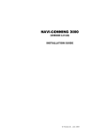
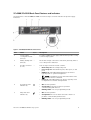
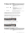
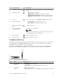
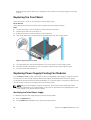
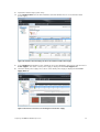
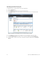
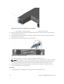
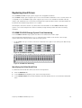
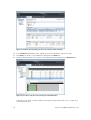
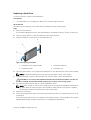
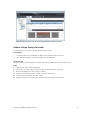
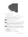
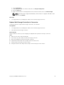
Dell Storage Center
SCv2000 and SCv2020 Storage System
Owner’s Manual
Regulatory Model: E09J, E10J
Regulatory Type: E09J001, E10J001
Notes, Cautions, and Warnings
NOTE: A NOTE indicates important information that helps you make better use of your computer.
CAUTION: A CAUTION indicates either potential damage to hardware or loss of data and tells you
how to avoid the problem.
WARNING: A WARNING indicates a potential for property damage, personal injury, or death.
Copyright © 2015 Dell Inc. All rights reserved. This product is protected by U.S. and international copyright and
intellectual property laws. Dell™ and the Dell logo are trademarks of Dell Inc. in the United States and/or other
jurisdictions. All other marks and names mentioned herein may be trademarks of their respective companies.
2015 - 04
Rev. A00
Contents
About this Guide.......................................................................................................5
Revision History..................................................................................................................................... 5
Audience................................................................................................................................................ 5
Contacting Dell......................................................................................................................................5
Related Publications.............................................................................................................................. 5
1 About the SCv2000/SCv2020 Storage System................................................7
SCv2000/SCv2020 Monitoring and Diagnostics................................................................................. 7
SCv2000/SCv2020 Storage System Hardware.................................................................................... 7
SCv2000/SCv2020 Storage System Front Panel Features and Indicators.................................... 7
SCv2000/SCv2020 Back-Panel Features and Indicators.............................................................. 9
SCv2000/SCv2020 Storage Controller Features and Indicators ................................................10
SCv2000/SCv2020 Drives............................................................................................................. 15
2 Replacing SCv2000/SCv2020 Components..................................................17
Safety Precautions............................................................................................................................... 17
Installation Safety Precautions...................................................................................................... 17
Electrical Safety Precautions......................................................................................................... 18
Electrostatic Discharge Precautions............................................................................................. 18
General Safety Precautions........................................................................................................... 18
Pre-Replacement Procedures............................................................................................................ 19
Sending Diagnostic Data Using Dell SupportAssist...................................................................... 19
Shutting Down a Storage Controller............................................................................................ 19
Shutting Down the Storage System.............................................................................................. 19
Replacing the Front Bezel...................................................................................................................20
Replacing Power Supply/Cooling Fan Modules................................................................................ 20
Identifying the Failed Power Supply............................................................................................. 20
Identifying the Failed Cooling Fan................................................................................................ 22
Replacing a Power Supply/Cooling Fan Module......................................................................... 23
Replacing Hard Drives.........................................................................................................................25
SCv2000/SCv2020 Storage System Drive Numbering................................................................25
Identifying the Failed Hard Drive.................................................................................................. 25
Replacing a Hard Drive..................................................................................................................27
Replacing the Storage Controller Battery.......................................................................................... 29
Replacing a Storage Controller.......................................................................................................... 29
Identify the Failed Storage Controller.......................................................................................... 30
Replace a Single Storage Controller............................................................................................. 31
3
Replace Both Storage Controllers in Succession........................................................................ 33
Replace Both Storage Controllers Simultaneously......................................................................35
Replacing Rack Rails............................................................................................................................35
Post-Replacement Procedures.......................................................................................................... 36
Start up the Storage System..........................................................................................................36
Sending Diagnostic Data Using Dell SupportAssist......................................................................36
3 Troubleshooting SCv2000/SCv2020 Components..................................... 37
Troubleshooting Power Supply/Cooling Fan Modules......................................................................37
Troubleshooting Hard Drives..............................................................................................................37
Troubleshooting Storage Controllers................................................................................................ 38
4 SCv2000/SCv2020 Technical Specifications................................................39
Technical Specifications..................................................................................................................... 39
4
Preface
About this Guide
This guide describes how to perform service and maintenance on an SCv2000/SCv2020 storage system.
Revision History
Document Number: 3CC1P
Revision
Date
Description
A00
April 2015
Initial release
Audience
The information provided in this Owner’s Manual is intended for use by Dell end users.
Contacting Dell
Dell provides several online and telephone-based support and service options. Availability varies by
country and product, and some services may not be available in your area.
To contact Dell for sales, technical support, or customer service issues go to www.dell.com/support.
•
For customized support, enter your system Service Tag on the support page and click Submit.
•
For general support, browse the product list on the support page and select your product.
Related Publications
The following documentation is available for the SCv2000/SCv2020 storage system.
•
Dell Storage Center SCv2000 and SCv2020 Storage System Getting Started Guide
Provides information about an SCv2000/SCv2020 storage system, such as installation instructions
and technical specifications.
•
Dell Storage Center SCv2000 and SCv2020 Storage System Deployment Guide
Provides information about an SCv2000/SCv2020 storage system, such as hardware features and
deployment instructions.
•
Dell Storage Center Release Notes
Contains information about new features and known and resolved issues for the Storage Center
software.
•
Dell Storage Center SCv2000 Series Virtual Media Update Instructions
Describes how to install Storage Center software on an SCv2000/SCv2020 storage system using
virtual media. Installing Storage Center software using the Storage Center Virtual Media option is
intended for use only by sites that cannot update Storage Center using standard methods.
•
Dell Storage Center Software Update Guide
5
Describes how to upgrade Storage Center software from an earlier version to the current version.
•
Dell Storage Center Command Utility Reference Guide
Provides instructions for using the Storage Center Command Utility. The Command Utility provides a
command-line interface (CLI) to enable management of Storage Center functionality on Windows,
Linux, Solaris, and AIX platforms.
•
Dell Storage Center Command Set for Windows PowerShell
Provides instructions for getting started with Windows PowerShell cmdlets and scripting objects that
interact with the Storage Center via the PowerShell interactive shell, scripts, and PowerShell hosting
applications. Help for individual cmdlets is available online.
•
Dell Storage Client Administrator’s Guide
Provides information about the Dell Storage Client and how it can be used to manage a Storage
Center.
•
Dell Enterprise Manager Administrator’s Guide
Contains in-depth feature configuration and usage information
•
Dell TechCenter
Provides technical white papers, best practice guides, and frequently asked questions about Dell
Storage products. Go to: http://en.community.dell.com/techcenter/storage/.
6
About the SCv2000/SCv2020 Storage
System
1
The SCv2000/SCv2020 storage system provides the central processing capabilities for the Storage
Center Operating System (OS) and management of RAID storage.
The SCv2000/SCv2020 storage system holds the physical disks that provide storage for the Storage
Center. If additional storage is needed, the SCv2000/SCv2020 also supports SC100/SC120 expansion
enclosures.
SCv2000/SCv2020 Monitoring and Diagnostics
The Storage Center Operating System (OS) generates alert messages for temperature, fan, disk, power,
and storage controller conditions. Use the Dell Storage Client to view these alerts.
The SCv2000/SCv2020 also has LED indicators that identify possible problems with the storage system.
NOTE: Dell OpenManage Server Administrator does not support the SCv2000/SCv2020.
SCv2000/SCv2020 Storage System Hardware
The SCv2000/SCv2020 is a 2U storage system that supports up to 24 2.5–inch hot-swappable SAS hard
drives installed vertically side-by-side.
The SCv2000/SCv2020 ships with two power/supply cooling fan modules and up to two redundant
storage controllers. The storage controller contains multiple I/O ports that provide communication with
front-end servers and back-end storage.
SCv2000/SCv2020 Storage System Front Panel Features and Indicators
The front panel of the SCv2000/SCv2020 contains power and status indicators, a system identification
button, and a seven-segment display.
In addition, the hard drives are installed and removed through the front of the storage system chassis.
About the SCv2000/SCv2020 Storage System
7
Figure 1. SCv2000 Front Panel View
Item
Name
1
Power indicator
Icon
Description
Lights when the storage system power is on.
•
•
2
Status indicator
Lights when at least one power supply is supplying power to
the storage system.
•
•
•
•
•
3
Off: No power
On steady green: At least one power supply is providing
power to the storage system
Identification
button
Off: No power
On steady blue: Power is on and firmware is running
Blinking blue:Storage system is busy booting or updating
On steady amber: Hardware detected fault
Blinking amber: Software detected fault
Lights when the storage system identification is enabled.
•
•
Off: Normal status
Blinking blue: Storage system identification enabled
4
Unit ID display
—
Displays the storage system identification number (01).
5
Hard drives
—
Up to 12 3.5–inch or 24 2.5–inch SAS hard drives
8
About the SCv2000/SCv2020 Storage System
SCv2000/SCv2020 Back-Panel Features and Indicators
The back panel of the SCv2000/SCv2020 shows the storage controller indicators and power supply
indicators.
Figure 2. SCv2000/SCv2020 Back Panel View
Item
Name
Icon
1
Power supply/
—
cooling fan module
(PSU) (2)
Contains a 580 W power supply and fans that provide cooling
for the storage system.
2
Battery backup unit —
(BBU) (2)
Allows the storage controller to shut down gracefully when a
loss of AC power is detected.
3
Storage controller
(1 or 2)
Each storage controller module contains:
—
Description
•
•
•
•
4
Cooling fan fault
indicator (2)
•
•
•
5
AC power fault
indicator (2)
•
•
•
About the SCv2000/SCv2020 Storage System
Back-end ports: Two 6 Gbps SAS ports
Front-end ports: Fibre Channel ports, iSCSI ports, or SAS
ports
MGMT port: Embedded Ethernet/iSCSI port, which is
typically used for system management
NOTE: The MGMT port can share iSCSI traffic if the
Flex Port license is installed.
REPL port: Embedded iSCSI port, which is typically used
for replication to another Storage Center
Off: Normal operation
Steady amber: Fan fault or there is a problem
communicating with the PSU
Blinking amber: PSU is in programming mode
Off: Normal operation
Steady Amber: A PSU has been removed or there is a
problem communicating with the PSU
Blinking amber: PSU is in programming mode
9
Item
Name
6
AC power status
indicator (2)
Icon
Description
•
•
•
7
DC power fault
indicator (2)
•
•
•
Off: AC power is off, or the power is on but the module is
not in a controller, or it may indicate a hardware fault
Steady green: AC power is on
Blinking green: AC power is on and the PSU is in standby
mode
Off: Normal operation
Steady amber: A PSU has been removed, or there is a DC
or other hardware fault, or there is a problem
communicating with the PSU
Blinking amber: PSU is in programming mode
8
Power socket (2)
—
Accepts a standard computer power cord.
9
Power switch (2)
—
Controls power for the storage system. There is one switch for
each power supply/cooling fan module.
SCv2000/SCv2020 Storage Controller Features and Indicators
The SCv2000/SCv2020 includes up to two storage controllers in two interface slots.
The storage controllers support Fibre Channel, iSCSI, or SAS front-end ports.
SCv2000/SCv2020 Storage Controller with Fibre Channel Front-End Ports
Features and indictors on a storage controller with Fibre Channel front-end ports.
Figure 3. Storage Controller with Four 8 Gb Fibre Channel Front-End Ports
Figure 4. Storage Controller with Two 16 Gb Fibre Channel Front-End Ports
Item Control/Feature
1
10
Battery status indicator
Icon Description
•
•
Blinking green (on 0.5 sec. / off 1.5 sec.): Battery heartbeat
Fast blinking green (on 0.5 sec. / off 0.5 sec.): Battery is
charging
About the SCv2000/SCv2020 Storage System
Item Control/Feature
2
Battery fault indicator
3
MGMT port
Icon Description
—
•
Steady green: Battery is ready
•
•
•
Off: No faults
Blinking amber: Correctable fault detected
Steady amber: Uncorrectable fault detected; replace battery
10 Mbps, 100 Mbps, or 1 Gbps Ethernet/iSCSI port used for
storage system management and access to the BMC
NOTE: To use the MGMT port as an iSCSI port for
replication to another Storage Center, a Flex Port license
and replication license are required. To use the MGMT port
as a front-end connection to host servers, a Flex Port
license is required.
4
REPL port
—
10 Mbps, 100 Mbps, or 1 Gbps Ethernet/iSCSI port used for
replication to another Storage Center (requires a replication
license)
NOTE: To use the RELP port as a front-end connection to
host servers, a Flex Port license is required.
5
SAS activity indicators
—
6
Storage controller
module status
On: Storage controller completed POST
7
Recessed power off
button
Powers down the storage controller if held for more than five
seconds
8
Storage controller
module fault
•
•
•
9
Recessed reset button
Reboots the storage controller forcing it to restart at the POST
process
10
Identification LED
•
•
•
11
USB port
Not for customer use on SCv2000/SCv2020 Storage Systems.
12
Diagnostic LEDs (8)
13
Serial port (3.5 mm mini
jack)
—
•
•
•
•
•
Off: Port is off
Steady green: Port is on, but without activity
Blinking green: Port is on and there is activity
Off: No faults
Steady amber: Firmware has detected an error
Blinking amber:Storage controller is performing POST
Off: Identification disabled
Blinking blue (for 15 sec.): Identification is enabled
Blinking blue (continuously): Storage controller shut down
to the Advanced Configuration and Power Interface (ACPI)
S5 state
Green LEDs 0–3: Low byte hex POST code
Green LEDs 4–7: High byte hex POST code
Not for customer use.
About the SCv2000/SCv2020 Storage System
11
Item Control/Feature
Icon Description
14
Four or two Fibre
—
Channel ports with three
LEDs per port
•
•
•
•
•
•
•
•
15
Mini-SAS port B
Back-end expansion port B
16
Mini-SAS port A
Back-end expansion port A
All off: No power
All on: Booting up
Blinking amber: 2 Gbps activity
Blinking green: 4 Gbps activity
Blinking yellow: 8 Gbps activity
Blinking amber and yellow: Beacon
All blinking (simultaneous): Firmware initialized
All blinking (alternating): Firmware fault
SCv2000/SCv2020 Storage Controller with iSCSI Front-End Ports
Features and indictors on a storage controller with iSCSI front-end ports.
Figure 5. SCv2000/SCv2020 Storage Controller with Four 1 GbE iSCSI Front-End Ports
Figure 6. SCv2000/SCv2020 Storage Controller with Two 10 GbE iSCSI Front-End Ports
Item Control/Feature
1
2
12
Battery status indicator
Battery fault indicator
Icon Description
•
•
•
Blinking green (on 0.5 sec. / off 1.5 sec.): Battery heartbeat
Fast blinking green (on 0.5 sec. / off 0.5 sec.): Battery is
charging
Steady green: Battery is ready
•
•
•
Off: No faults
Blinking amber: Correctable fault detected
Steady amber: Uncorrectable fault detected; replace battery
About the SCv2000/SCv2020 Storage System
Item Control/Feature
Icon Description
3
—
MGMT port
10 Mbps, 100 Mbps, or 1 Gbps Ethernet port used for storage
system management and access to the BMC
NOTE: To use the MGMT port as an iSCSI port for
replication to another Storage Center, a Flex Port license
and replication license are required. To use the MGMT port
as a front-end connection to host servers, a Flex Port
license is required.
4
REPL port
—
10 Mbps, 100 Mbps, or 1 Gbps Ethernet/iSCSI port used for
replication to another Storage Center
NOTE: To use the RELP port as a front-end connection to
host servers, a Flex Port license is required.
5
SAS activity indicators
—
6
Storage controller
module status
On: Storage controller completed POST
7
Recessed power off
button
Powers down the storage controller if held for more than five
seconds
8
Storage controller
module fault
•
•
•
9
Recessed reset button
Reboots the storage controller forcing it to restart at the POST
process
10
Identification LED
•
•
•
11
USB port
Not for customer use on SCv2000/SCv2020 Storage Systems.
12
Diagnostic LEDs (8)
13
Serial port (3.5 mm mini
jack)
14
Four or two iSCSI ports
with two LEDs per port
—
•
•
•
•
•
Off: Port is off
Steady green: Port is on, but without activity
Blinking green: Port is on and there is activity
Off: No faults
Steady amber: Firmware has detected an error
Blinking amber:Storage controller is performing POST
Off: Identification disabled
Blinking blue (for 15 sec.): Identification is enabled
Blinking blue (continuously): Storage controller shut down
to the Advanced Configuration and Power Interface (ACPI)
S5 state
Green LEDs 0–3: Low byte hex POST code
Green LEDs 4–7: High byte hex POST code
Not for customer use.
—
•
Off: No power
•
Steady Amber: Link
•
Blinking Green: Activity
15
Mini-SAS port B
Back-end expansion port B
16
Mini-SAS port A
Back-end expansion port A
About the SCv2000/SCv2020 Storage System
13
SCv2000/SCv2020 Storage Controller with SAS Front-End Ports
Features and indictors on a storage controller with SAS front-end ports.
Figure 7. SCv2000/SCv2020 Storage Controller with Four 12 Gb SAS Front-End Ports
Item Control/Feature
1
Icon Description
Battery status indicator
2
Battery fault indicator
3
MGMT port
•
•
—
•
Blinking green (on 0.5 sec. / off 1.5 sec.): Battery heartbeat
Fast blinking green (on 0.5 sec. / off 0.5 sec.): Battery is
charging
Steady green: Battery is ready
•
•
•
Off: No faults
Blinking amber: Correctable fault detected
Steady amber: Uncorrectable fault detected; replace battery
10 Mbps, 100 Mbps, or 1 Gbps Ethernet port used for storage
system management and access to the BMC
NOTE: To use the MGMT port as an iSCSI port for
replication to another Storage Center, a Flex Port license
and replication license are required. To use the MGMT port
as a front-end connection to host servers, a Flex Port
license is required.
4
REPL port
—
10 Mbps, 100 Mbps, or 1 Gbps Ethernet/iSCSI port used for
replication to another Storage Center
NOTE: To use the RELP port as a front-end connection to
host servers, a Flex Port license is required.
5
SAS activity indicators
6
Storage controller
module status
On: Storage controller completed POST
7
Recessed power off
button
Powers down the storage controller if held for more than five
seconds
8
Storage controller
module fault
•
•
•
14
—
•
•
•
Off: Port is off
Steady green: Port is on, but without activity
Blinking green: Port is on and there is activity
Off: No faults
Steady amber: Firmware has detected an error
Blinking amber:Storage controller is performing POST
About the SCv2000/SCv2020 Storage System
Item Control/Feature
Icon Description
9
Recessed reset button
Reboots the storage controller forcing it to restart at the POST
process
10
Identification LED
•
•
•
11
USB port
Not for customer use on SCv2000/SCv2020 Storage Systems.
12
Diagnostic LEDs (8)
13
Serial port (3.5 mm mini
jack)
14
Four Mini-SAS High
Density (HD) ports
—
•
•
Off: Identification disabled
Blinking blue (for 15 sec.): Identification is enabled
Blinking blue (continuously): Storage controller shut down
to the Advanced Configuration and Power Interface (ACPI)
S5 state
Green LEDs 0–3: Low byte hex POST code
Green LEDs 4–7: High byte hex POST code
Not for customer use.
—
Front-end connectivity ports
NOTE:
The mini-SAS HD ports are for front-end connectivity only and
cannot be used for back-end expansion.
15
Mini-SAS port B
Back-end expansion port B
16
Mini-SAS port A
Back-end expansion port A
SCv2000/SCv2020 Drives
Dell Enterprise hard disk drives (HDDs) and Enterprise Solid-State Drives (eSSDs) are the only drives that
can be installed in an SCv2000/SCv2020 storage system. If a non-Dell Enterprise drive is installed,
Storage Center prevents the drive from being managed.
The drives in an SCv2000 storage system are installed horizontally. The drives in an SCv2020 storage
system are installed vertically. The indicators on the drives provide status and activity information.
Figure 8. SCv2000/SCv2020 Drive Indicators
Item
Name
Indicator Code
1
Drive activity
indicator
•
•
Blinking green: Drive activity
Steady green: Drive is detected and there are no faults
2
Drive status
indicator
•
•
Off: Normal operation
Blinking amber (on 1 sec. / off 1 sec.): Drive identification is enabled
About the SCv2000/SCv2020 Storage System
15
Item
Name
Indicator Code
•
•
16
Blinking amber (on 2 sec. / off 1 sec.): Drive failed
Steady amber: Drive is safe to remove
About the SCv2000/SCv2020 Storage System
Replacing SCv2000/SCv2020
Components
2
This section describes how to remove and install components of an SCv2000/SCv2020 storage system.
This document assumes that the customer has received the replacement component and is ready to
install it.
Safety Precautions
Always follow these safety precautions to avoid injury and damage to Storage Center equipment.
If equipment described in the document is used in a manner not specified by Dell, the protection
provided by the equipment may be impaired. For your safety and protection, observe the rules described
in the following sections.
NOTE: See the safety and regulatory information that shipped with each Storage Center
component. Warranty information may be included within this document or as a separate
document.
Installation Safety Precautions
Follow these safety precautions:
•
Dell recommends that only individuals with rack-mounting experience install an SCv2000/SCv2020
storage system in a rack.
•
Make sure the storage system is fully grounded at all times to prevent damage from electrostatic
discharge.
•
When handling the storage system hardware, you should use an electrostatic wrist guard (not
included) or a similar form of protection.
The storage system chassis MUST be mounted in a rack; the following safety requirements must be
considered when doing so:
•
The rack construction must be capable of supporting the total weight of the installed chassis and the
design should incorporate stabilizing features suitable to prevent the rack tipping or being pushed
over during installation or in normal use.
•
To avoid danger of the rack toppling over, do not slide more than one chassis out of the rack at a
time.
•
The rack design should take into consideration the maximum operating ambient temperature for the
unit, which is 57°C.
Replacing SCv2000/SCv2020 Components
17
Electrical Safety Precautions
Always follow electrical safety precautions to avoid injury and damage to Storage Center equipment.
WARNING: Disconnect power from the storage system when removing or installing components
that are not hot-swappable. When disconnecting power, first power down the storage system
using the Dell Storage Client and then unplug the power cords from all the power supplies in the
storage system.
•
Provide a suitable power source with electrical overload protection. All Storage Center components
must be grounded before applying power. Make sure that there is a safe electrical earth connection to
power supply cords. Check the grounding before applying power.
•
The plugs on the power supply cords are used as the main disconnect device. Make sure that the
socket outlets are located near the equipment and are easily accessible.
•
Know the locations of the equipment power switches and the room's emergency power-off switch,
disconnection switch, or electrical outlet.
•
Do not work alone when working with high-voltage components.
•
Use rubber mats specifically designed as electrical insulators.
•
Do not remove covers from the power supply unit. Disconnect the power connection before
removing a power supply from the storage system.
•
Do not remove a faulty power supply unless you have a replacement model of the correct type ready
for insertion. A faulty power supply must be replaced with a fully operational module power supply
within 24 hours.
•
Unplug the storage system chassis before you move it or if you think it has become damaged in any
way. When powered by multiple AC sources, disconnect all supply power for complete isolation.
Electrostatic Discharge Precautions
Always follow electrostatic discharge (ESD) precautions to avoid injury and damage to Storage Center
equipment.
Electrostatic discharge (ESD) is generated by two objects with different electrical charges coming into
contact with each other. The resulting electrical discharge can damage electronic components and
printed circuit boards. Follow these guidelines to protect your equipment from ESD:
•
Dell recommends that you always use a static mat and static strap while working on components in
the interior of the storage system chassis.
•
Observe all conventional ESD precautions when handling plug-in modules and components.
•
Use a suitable ESD wrist or ankle strap.
•
Avoid contact with backplane components and module connectors.
•
Keep all components and printed circuit boards (PCBs) in their antistatic bags until ready for use.
General Safety Precautions
Always follow general safety precautions to avoid injury and damage to Storage Center equipment.
•
Keep the area around the storage system chassis clean and free of clutter.
•
Place any system components that have been removed away from the storage system chassis or on a
table so that they are not in the way of foot traffic.
•
While working on the storage system chassis, do not wear loose clothing such as neckties and
unbuttoned shirt sleeves, which can come into contact with electrical circuits or be pulled into a
cooling fan.
18
Replacing SCv2000/SCv2020 Components
•
Remove any jewelry or metal objects from your body because they are excellent metal conductors
that can create short circuits and harm you if they come into contact with printed circuit boards or
areas where power is present.
•
Do not lift a storage system chassis by the handles of the power supply units (PSUs). They are not
designed to hold the weight of the entire chassis, and the chassis cover may become bent.
•
Before moving a storage system chassis, remove the PSUs to minimize weight.
•
Do not remove drives until you are ready to replace them.
NOTE: To ensure proper storage system cooling, hard drive blanks must be installed in any hard
drive slot that is not occupied.
Pre-Replacement Procedures
Perform the procedures described in this section before replacing a component of an SCv2000/SCv2020
storage system.
Sending Diagnostic Data Using Dell SupportAssist
Use Dell SupportAssist to send diagnostic data to Dell Technical Support Services.
1.
Click Send SupportAssist Data Now. The Send Support Assist Data Now dialog box appears.
2.
Select Storage Center Configuration and Detailed Logs.
3.
Click OK.
Shutting Down a Storage Controller
If you are replacing a storage controller, use the Dell Storage Client to shut down the storage controller.
About this task
If the storage system has two storage controllers, shutting down one storage controller causes the
Storage Center to fail over to the other storage controller. which continues to process I/O. If the storage
system has only one storage controller, shutting it down results in a system outage.
Steps
1.
Click the Hardware tab.
2.
In the Hardware tab navigation pane, select the storage controller to shut down.
3.
In the right pane, click Shutdown/Restart Controller. The Shutdown/Restart Controller dialog box
appears.
4.
Select Shutdown from the drop-down menu.
5.
Click OK. The selected storage controller is shut down.
Shutting Down the Storage System
If you are replacing the storage system chassis or rack rails, use the Dell Storage Client to shut down the
storage system.
About this task
CAUTION: Shutting down the storage system results in a system outage.
Steps
1.
Select Actions → System → Shutdown/Restart. The Shutdown/Restart dialog box appears.
2.
Select Shutdown from the first drop-down menu.
3.
Click OK.
Replacing SCv2000/SCv2020 Components
19
After the storage system shuts down, unplug the power cables from the power supply/cooling fan
modules.
Replacing the Front Bezel
The front bezel is a cover for the front panel of the storage system.
About this task
The front bezel must be removed from the front panel when replacing hard drives.
Steps
1. Use the system key to unlock the keylock at the left end of the bezel.
2.
Lift the release latch next to the keylock.
3.
Rotate the left end of the bezel away from the front panel.
4.
Unhook the right end of the bezel and pull the bezel away from the storage system.
Figure 9. Replacing the Front Bezel
5.
Hook the right end of the replacement bezel onto the front panel of the storage system.
6.
Insert the left end of the bezel into the securing slot until the release latch snaps into place.
7.
Secure the bezel with the keylock.
Replacing Power Supply/Cooling Fan Modules
The SCv2000/SCv2020 storage system supports two hot-swappable power supply/cooling fan modules.
The fans that cool the storage system and the power supplies are integrated into the power supply/
cooling fan module and cannot be replaced separately. If one power supply/cooling fan module fails, the
second module continues to provide power to the storage system.
NOTE: When a power supply/cooling fan module fails, the fan speed in the remaining module
increases significantly to provide adequate cooling. The fan speed decreases gradually when a new
power supply/cooling fan module is installed.
Identifying the Failed Power Supply
To determine which power supply failed, use the Dell Storage Client.
1.
Click the Hardware tab.
2.
In the Hardware tab navigation pane, select the Storage Center.
20
Replacing SCv2000/SCv2020 Components
3.
Expand the failed storage system entry.
4.
In the Hardware Alerts area, find the hardware alert that identifies the enclosure with the failed
power supply.
Figure 10. Hardware Alert Identifying the Enclosure with the Failed Power Supply
5.
In the Hardware tab navigation pane, expand the enclosure identified in the previous step and select
Power Supplies. The status of each power supply is displayed in the Power Supplies tab.
6.
Select the failed power supply. The location of the failed power supply is displayed in the Power
Supply View tab.
Figure 11. Rear View of the Enclosure Showing the Failed Power Supply
Replacing SCv2000/SCv2020 Components
21
Identifying the Failed Cooling Fan
To determine which cooling fan failed, use the Dell Storage Client.
1.
Click the Hardware tab.
2.
In the Hardware tab navigation pane, select the Storage Center.
3.
In the Hardware Alerts area, find the hardware alert that identifies the enclosure with the failed
cooling fan.
Figure 12. Hardware Alert Identifying the Enclosure with the Failed Cooling Fan
4.
In the Hardware tab navigation pane, expand the enclosure identified in the previous step.
5.
Select Cooling Fan Sensors. The status of each cooling fan is displayed in the Cooling Fans tab.
6.
Select the failed cooling fan. The location of the failed cooling fan is displayed in the Cooling Fan
View tab.
22
Replacing SCv2000/SCv2020 Components
Figure 13. Rear View of the Enclosure Showing the Failed Cooling Fan
Replacing a Power Supply/Cooling Fan Module
Use this procedure to replace a failed power supply/cooling fan module.
Prerequisites
1.
Use SupportAssist to send diagnostic data to Dell Technical Support Services.
About this task
You can replace power supply/cooling fan modules one at a time without shutting down the storage
system.
Steps
1. Press the power switch on the power supply/cooling fan module to turn it off.
2.
Remove the hook-and-loop strap that secures the power cable and disconnect the power cable
from the power supply/cooling fan module.
3.
Push the release tab on the power supply/cooling fan module and slide it out of the chassis using the
handle.
CAUTION: The power supply/cooling fan modules are heavy. To avoid injury, use both hands
while removing the module.
Replacing SCv2000/SCv2020 Components
23
Figure 14. Removing a Power Supply/Cooling Fan Module
1.
Power supply/cooling fan module
2.
Storage system chassis
4.
Slide the replacement power supply/cooling fan module into the chassis until it is fully seated and
the release tab clicks into place.
5.
Connect the power cable to the power supply/cooling fan module and make sure that the cable is
plugged into a power outlet.
6.
Secure the power cable using the hook-and-loop strap.
Figure 15. Securing the Power Cable
7.
Press the power switch on the power supply/cooling fan module to turn it on.
NOTE: Allow several seconds for the storage system to recognize the power supply/cooling fan
module and determine its status. When the power supply/cooling fan module is functioning
properly, the AC power status indicator turns green and the three fault indicators are off.
8.
In the Dell Storage Client, make sure that the replacement power supply/cooling fan module is
recognized and shown as up and running.
Next steps
1.
24
Use SupportAssist to send diagnostic data to Dell Technical Support Services.
Replacing SCv2000/SCv2020 Components
Replacing Hard Drives
The SCv2000/SCv2020 storage systems support hot-swappable hard drives.
The SCv2000 storage system supports up to 12 3.5-inch hard drives installed in a four-column, three-row
configuration. The SCv2020 storage system supports up to 24 2.5-inch hard drives installed vertically
side-by-side. Hard drives are connected to a backplane through hard drive carriers. Hard drive blanks are
installed in the hard drive bays that are not occupied.
Dell Enterprise Plus Drives are the only drives that can be installed in an SCv2000/SCv2020 storage
system. If a non Dell Enterprise Plus Drive is installed, Storage Center prevents the drive from being
managed.
SCv2000/SCv2020 Storage System Drive Numbering
In an SCv2000/SCv2020 storage system, the drives are numbered from left to right.
Dell Storage Client identifies drives as XX-YY, where XX is the number of the unit ID of the storage
system, and YY is the drive position inside the storage system.
•
An SCv2000 holds up to 12 drives, which are numbered left to right in rows starting from 0 at the topleft drive.
Figure 16. SCv2000 Drive Numbering
•
An SCv2020 holds up to 24 drives, which are numbered left to right starting from 0.
Figure 17. SCv2020 Drive Numbering
Identifying the Failed Hard Drive
To determine which hard drive failed, use the Dell Storage Client.
1.
Click the Hardware tab.
2.
In the Hardware tab navigation pane, select the Storage Center.
3.
In the Hardware Alerts area, find the hardware alert that identifies the enclosure with the failed hard
drive.
Replacing SCv2000/SCv2020 Components
25
Figure 18. Hardware Alert Identifying the Enclosure with the Failed Hard Drive
4.
In the Hardware tab navigation pane, expand the enclosure identified in the previous step.
5.
Select Disks. The status of each hard drive is displayed in the Disks tab.
6.
Select the failed hard drive. The location of the failed hard drive is displayed in the Disk View tab.
Figure 19. Front View of the Enclosure Showing the Failed Hard Drive
If desired, you can open a wizard to guide you through the replacement steps. To do so, right-click
on the failed hard drive.
26
Replacing SCv2000/SCv2020 Components
Replacing a Hard Drive
Use this procedure to replace a failed hard drive.
Prerequisites
1.
Use SupportAssist to send diagnostic data to Dell Technical Support Services.
About this task
Hard drives can be replaced one at a time without shutting down the storage system.
Steps
1. Remove the front bezel.
A solid amber light appears next to the failed hard drive, indicating the drive is ready to be removed.
2.
Press the release button to open the hard drive carrier release handle.
3.
Slide the hard drive out until it is free of the hard drive slot.
Figure 20. Replacing a Hard Drive
4.
1.
Hard drive carrier release handle
2.
Hard drive indicators
3.
Hard drive carrier
4.
Hard drive slot
Press the release button on the replacement hard drive to open the hard drive carrier release handle.
NOTE: Hold the hard drive by the plastic part of the hard drive carrier or the handle.
5.
Insert the hard drive carrier into the hard drive slot until the carrier contacts the backplane.
CAUTION: Do not remove the hard drive blanks that are installed in hard drive slots that are
not occupied. The hard drive blanks ensure proper cooling of the storage system.
6.
Close the hard drive carrier handle to lock the hard drive in place.
NOTE: Allow several seconds for the storage system to recognize the hard drive and determine
its status. When functioning properly, the hard drive’s status indicator turns green. In addition,
the hard drive indicator turns green in the Dell Storage Client.
7.
Replace the front bezel.
8.
In the Dell Storage Client, make sure that the replacement hard drive is recognized and shown as up
and running.
If the Dell Storage Client informs you that there are unassigned disks, see the Storage Center System
Manager Administrator’s Guide for instructions on managing unassigned disks.
Replacing SCv2000/SCv2020 Components
27
Next steps
1.
Use SupportAssist to send diagnostic data to Dell Technical Support Services.
Install Hard Drives in Storage System
An SCv2000/SCv2020 storage system is shipped with drives installed and empty drive blanks are inserted
in the unused slots.
Prerequisites
Use these instructions if you have purchased new hard drives for your SCv2000/SCv2020 storage system
About this task
The following instructions show the installation of the Dell Enterprise hard drive for reference only.
Figure 21. Installing Dell Enterprise Hard Drives in a Storage System
Steps
1. Remove empty drive blank.
2.
Open the hard drive carrier handle and insert the hard drive carrier into the hard drive slot.
Start on the left side of the storage system with slot 0 and install drives from left to right.
3.
Slide the drive into the slot until the hard drive carrier contacts the backplane.
4.
Close the hard drive carrier handle to lock the hard drive in place.
5.
Continue to push firmly until you hear a click and the hard drive carrier handle fully engages.
6.
Insert drive blanks into any open slots in the chassis.
All of the drive slots in the storage system must be filled with a drive or drive blank.
Related Links
Storage System Drive Numbering
28
Replacing SCv2000/SCv2020 Components
Replacing the Storage Controller Battery
Each storage controller contains a hot-swappable battery. The battery supplies enough emergency
power to back up vital information in the event of AC power loss.
Prerequisites
1.
Use SupportAssist to send diagnostic data to Dell Technical Support Services.
About this task
Storage controller batteries can be replaced without shutting down the storage system.
Steps
1. Press the release tab and then slide the battery out of the storage controller.
Figure 22. Replace the Storage Controller Battery
1.
Battery
3.
Storage controller
2.
Release tab
2.
Align the replacement battery with the slot on the storage controller.
3.
Slide the battery into the storage controller until the release tab clicks into place.
Next steps
1.
Use SupportAssist to send diagnostic data to Dell Technical Support Services.
Replacing a Storage Controller
The SCv2000/SCv2020 storage system supports redundant hot-swappable storage controllers.
Storage controllers provide the following data path and storage management functions for the storage
system:
•
Monitoring and controlling some storage system environment elements such as temperature, fan,
power supplies, and storage system LEDs
Replacing SCv2000/SCv2020 Components
29
•
Controlling access to hard drives
•
Communicating storage attributes and states to the storage system
NOTE: Do not return the storage controller battery with the failed storage controller. A new battery
is not included with a replacement storage controller.
Identify the Failed Storage Controller
To determine which storage controller failed, use the Dell Storage Client .
1.
Click the Hardware tab.
2.
In the Hardware tab navigation pane, select the Storage Center.
3.
In the Hardware Alerts area, find the hardware alert that identifies the enclosure with the failed
storage controller.
Figure 23. Hardware Alert Identifying the Enclosure with the Failed Storage Controller
4.
In the Hardware tab navigation pane, expand the Enclosures entry.
5.
Click I/O Modules. The status of each storage controller is displayed in the I/O Modules tab.
6.
Select the failed storage controller to display its location in the IO Module View tab.
30
Replacing SCv2000/SCv2020 Components
Figure 24. Rear View of the Enclosure Showing the Failed Storage Controller
Replace a Single Storage Controller
Use this procedure to replace a single failed storage controller.
Prerequisites
1.
Use SupportAssist to send diagnostic data to Dell Technical Support Services.
2.
Shut down the storage controller using the Dell Storage Client.
About this task
Storage controllers can be replaced one at a time without shutting down the storage system.
Steps
1. Make sure all of the cables are labeled.
2.
Disconnect all of the cables from the storage controller that was shut down.
3.
Remove the battery from the storage controller.
4.
Squeeze the release tab on the storage controller release lever.
5.
Pull the release lever away from the chassis.
6.
Grasp the release lever and pull the storage controller away from the chassis.
Replacing SCv2000/SCv2020 Components
31
Figure 25. Replacing a Storage Controller
7.
1.
Power supply/cooling fan module
3.
Release lever
2.
Storage controller
Locate the battery removed in a previous step and insert it into the replacement storage controller.
a. Align the battery with the slot on the storage controller.
b. Slide the battery into the storage controller until the release tab clicks into place.
8.
Insert the replacement storage controller into the chassis until it is fully seated.
NOTE: The bottom storage controller is installed upside down.
9.
Reconnect the cables to the storage controller.
10. Push the release lever toward the chassis until it clicks into place. The storage controller is powered
on.
NOTE: When a storage controller is powered on, there is a one‐minute delay while the storage
controller prepares to boot. During this time, the only indication that the storage controller is
powered on are the LEDs on the storage controller. After the one‐minute delay, the fans and
LEDs turn on as an indication that the storage controller is starting up.
11. In the Dell Storage Client, make sure that the replacement storage controller is recognized and
shown as up and running.
NOTE: If the Storage Center software on the replacement storage controller is older than the
software on the existing storage controller, the storage system updates the replacement
storage controller with the software version on the existing storage controller. The Storage
Center software update on the replacement storage controller may take from 15 to 45 minutes
to complete.
12. Clear the swap status for the temperature sensor and I/O module.
a.
b.
c.
d.
32
Click the Hardware tab.
In the Hardware tab navigation pane, expand the enclosure.
Select Temperature Sensors.
In the right pane, right-click the sensor, then click Request Swap Clear.
Replacing SCv2000/SCv2020 Components
e.
f.
g.
h.
Select I/O Modules.
In the right pane, right-click the module, then click Request Swap Clear.
Click the Alerts tab.
Right-click the alerts for the temperature sensor and I/O modules, then click Acknowledge.
NOTE: The alerts may not appear immediately. If the alerts do not appear, wait 10 seconds
and then click Refresh.
Next steps
1.
Use SupportAssist to send diagnostic data to Dell Technical Support Services.
Replace Both Storage Controllers in Succession
Use this procedure to replace both storage controllers, one at a time.
Prerequisites
1.
Use SupportAssist to send diagnostic data to Dell Technical Support Services.
2.
Shut down the left storage controller.
About this task
This procedure is useful if you are swapping out degraded, but operational storage controllers.
Steps
1. Make sure all of the cables are labeled.
2.
Disconnect all of the cables from the left storage controller
3.
Remove the battery from the left storage controller.
4.
Squeeze the release tab on the storage controller release lever.
5.
Pull the release lever away from the chassis.
6.
Grasp the release lever and pull the storage controller away from the chassis.
Replacing SCv2000/SCv2020 Components
33
Figure 26. Replacing a Storage Controller
1.
7.
Storage controller
2.
Release lever
Locate the battery removed in a previous step and insert it into the replacement storage controller.
a. Align the battery with the slot on the storage controller.
b. Slide the battery into the storage controller until the release tab clicks into place.
8.
Insert the replacement storage controller into the chassis until it is fully seated.
9.
Reconnect all the cables to the left storage controller.
10. Push the release lever toward the chassis until it clicks into place. The storage controller is powered
on.
NOTE: When a storage controller is powered on, there is a one‐minute delay while the storage
controller prepares to boot. During this time, the only indication that the storage controller is
powered on are the LEDs on the storage controller. After the one‐minute delay, the fans and
LEDs turn on as an indication that the storage controller is starting up.
11. In the Dell Storage Client, make sure that the replacement storage controller is recognized and
shown as up and running.
NOTE: If the Storage Center software on the replacement storage controller is older than the
software on the existing storage controller, the storage system updates the replacement
storage controller with the software version on the existing storage controller. The Storage
Center software update on the replacement storage controller may take from 15 to 45 minutes
to complete.
12. Clear the swap status for the temperature sensor and I/O module.
a.
b.
c.
d.
e.
f.
g.
34
Click the Hardware tab.
In the Hardware tab navigation pane, expand the enclosure.
Select Temperature Sensors.
In the right pane, right-click the sensor, then click Request Swap Clear.
Select I/O Modules.
In the right pane, right-click the module, then click Request Swap Clear.
Click the Alerts tab.
Replacing SCv2000/SCv2020 Components
h. Right-click the alerts for the temperature sensor and I/O modules, then click Acknowledge.
NOTE: The alerts may not appear immediately. If the alerts do not appear, wait 10 seconds
and then click Refresh.
13. Clear the swap status for the temperature sensor and acknowledge the alert.
a.
b.
c.
d.
e.
f.
Click the Hardware tab.
In the Hardware tab navigation pane, expand the enclosure.
Select Temperature Sensors.
In the right pane, right-click the sensor, then click Request Swap Clear.
Click the Alerts tab.
Right-click the alert and select Acknowledge.
NOTE: The alert may not appear immediately. If the alert does not appear, wait 10 seconds
and then click Refresh.
14. Shut down the other storage controller and repeat the previous steps.
Next steps
1.
Use SupportAssist to send diagnostic data to Dell Technical Support Services.
Replace Both Storage Controllers Simultaneously
If you need to replace both storage controllers at the same time, contact Dell Technical Support Services
for assistance.
Replacing Rack Rails
Rack rails are used to install the SCv2000/SCv2020 storage system into a rack.
Prerequisites
1.
Use SupportAssist to send diagnostic data to Dell Technical Support Services.
2.
Shut down the storage system using the Dell Storage Client.
About this task
Use this procedure to replace rack rails.
NOTE: Replacing rack rails must be performed during a scheduled maintenance window when the
Storage Center system is unavailable to the network.
Steps
1.
Make sure all of the cables are labeled.
2.
Disconnect all of the cables from the storage system.
3.
Remove the storage system from the rack rails.
4.
Remove the rack rails from the rack.
5.
Install the replacement rack rails in the rack.
6.
Install the storage system in the rack rails.
7.
Reconnect the cables to the storage system.
8.
Start up the storage system.
Next steps
1.
Use SupportAssist to send diagnostic data to Dell Technical Support Services.
Replacing SCv2000/SCv2020 Components
35
Post-Replacement Procedures
After replacing a component in the SCv2000/SCv2020 storage system, start up the storage system if it
was previously shut down and use SupportAssist to send diagnostic data to Dell Technical Support
Services.
Start up the Storage System
If the storage system was previously shut down, perform this procedure to start it up.
1.
Plug the power cables into the power supply/cooling fan modules of the storage system.
2.
Turn on the storage system by pressing the power switches on the power supply/cooling fan
modules.
NOTE: When the SCv2000/SCv2020 storage system is powered on, there is a one-minute delay
while the SCv2000/SCv2020 prepares to boot. During this time, the only indication that the
SCv2000/SCv2020 is powered on are the LEDs on the storage controllers. After the oneminute delay, the SCv2000/SCv2020 fans and LEDs turn on as an indication that the storage
system is starting to come up.
3.
Use the Dell Storage Client to make sure the replacement part is recognized and shown as up and
running.
Sending Diagnostic Data Using Dell SupportAssist
Use Dell SupportAssist to send diagnostic data to Dell Technical Support Services.
1.
Click Send SupportAssist Data Now. The Send Support Assist Data Now dialog box appears.
2.
Select Storage Center Configuration and Detailed Logs.
3.
Click OK.
36
Replacing SCv2000/SCv2020 Components
Troubleshooting SCv2000/SCv2020
Components
3
This section contains basic troubleshooting steps for components inside the SCv2000/SCv2020 storage
system.
Troubleshooting Power Supply/Cooling Fan Modules
Use these steps to troubleshoot power supply/cooling fan modules.
1.
Check the status of the power supply/cooling fan module using the Dell Storage Client.
2.
Determine the status of the power supply/cooling fan module indicators.
•
If the power supply/cooling fan module fault indicator is lit, the power supply/cooling fan has
failed.
•
If the AC power indicator is not lit, check the power cord and power source into which the power
supply is plugged:
– Connect another device to the power source and check whether the device works.
– Connect the power cord to a different power source.
3.
– Replace the power cord.
Reseat the power supply/cooling fan module by removing and reinstalling it.
NOTE: Allow several seconds for the storage system to recognize the power supply/cooling fan
modules and determine its status.
Troubleshooting Hard Drives
Use these steps to troubleshoot hard drives.
1.
Check the status of the hard drive using the Dell Storage Client.
2.
Determine the status of the hard drive indicators.
•
3.
If the hard drive status indicator blinks amber on 2 seconds / off 1 second, the hard drive has
failed.
• If the hard drive status indicator is not lit, proceed to the next step.
Check the connectors and reseat the hard drive.
a. Remove the hard drive.
b. Check the hard drive and the backplane to ensure that the connectors are not damaged.
c. Reinstall the hard drive. Make sure the hard drive makes contact with the backplane.
Troubleshooting SCv2000/SCv2020 Components
37
Troubleshooting Storage Controllers
Use these steps to troubleshoot storage controllers.
1.
Check the status of the storage controller using the Dell Storage Client.
2.
Check the pins and reseat the storage controller.
a. Remove the storage controller.
b. Verify that the pins on the storage system backplane and the storage controller are not bent.
c. Reinstall the storage controller.
3.
Determine the status of the storage controller link status indicators. If the indicators are not green,
check the cables.
a.
b.
c.
d.
38
Shut down the storage controller.
Reseat the cables on the storage controller.
Restart the storage controller.
Recheck the link status indicators. If the link status indicators are not green, replace the cables.
Troubleshooting SCv2000/SCv2020 Components
SCv2000/SCv2020 Technical
Specifications
4
This section contains technical specifications of the SCv2000/SCv2020 storage system.
Technical Specifications
The technical specifications of the SCv2000/SCv2020 storage systems are displayed in the following
tables.
Drives
SAS hard drives
SCv2000: Up to 12 3.5-inch SAS hot-swappable hard drives (6.0 Gbps)
SCv2020: Up to 24 2.5-inch SAS hot-swappable hard drives (6.0 Gbps)
Storage Controllers
Storage controllers
Up to two hot-swappable storage controllers with the following IO options:
•
•
•
•
•
Two 16 Gbps Fibre Channel ports
Four 8 Gbps Fibre Channel ports
Two 10 Gbps iSCSI ports
Four 1 Gbps iSCSI ports
Four 12 Gbps SAS ports
Storage Connectivity
Configurations
Storage Center supports up to 168 drives in one redundant-path SAS chain
•
•
An SCv2000 supports up to 13 SC100 expansion enclosures or 6 SC120
expansion enclosures
An SCv2020 supports up to 12 SC100 expansion enclosures or 6 SC120
expansion enclosures
Redundant Array of Independent Disks (RAID)
Controller
Two hot-swappable storage controllers
Management
RAID management using Dell Storage Client 2015 R1
SCv2000/SCv2020 Technical Specifications
39
Back-Panel Ports Connectors (per Storage Controller)
Fibre Channel, iSCSI, or
SAS connectors
Connection to a Fiber Channel fabric, iSCSI network, or a direct connection
to servers with SAS HBAs
Ethernet connectors
MGMT: 10 Mbps, 100 Mbps, or 1 Gbps embedded Ethernet port used for
Storage Center management
REPL: 10 Mbps, 100 Mbps, or 1 Gbps embedded iSCSI port used for
replication to another Storage Center
SAS connectors
6 Gbps SAS connectors for SAS port redundancy and additional expansion
enclosures
NOTE: SAS connectors are SFF-8086/SFF-8088 compliant
USB connector
One USB 3.0 connector.
Not for customer use on SCv2000/SCv2020 storage systems.
Serial connector
NOTE: Not for customer use
LED Indicators
•
One two-color LED indicator for system status.
One single-color LED indicator for power status.
Two digit, seven-segment display indicating the storage system ID
number
ID button with a single-color LED indicating startup and pressed states
Hard drive carrier
•
•
One single-color activity LED
One single-color LED status indicator per drive
Storage controller
•
•
•
•
•
•
Two single-color LEDs per Ethernet port indicating activity and link speed
Four dual-color LEDs per SAS connector indicating port activity and status
One single-color LED indicating status
One single-color LED indicating fault
One single-color LED for identification
Eight single-color LED for diagnostics
Power supply/cooling
fan
Four LED status indicators for Power Supply Status, AC Fail status, DC Fail
status, and Fan Fail status
Front panel
•
•
•
Power Supplies
AC power supply (per power supply)
Wattage
580 W (maximum wattage: 584 W)
Voltage
100–240 VAC (7.6–3.0 A)
Heat dissipation
SCv2000: 65 W at 230 VAC and 99 W at 115 VAC
SCv2020: 65 W at 230 VAC and 99 W at 115 VAC
40
SCv2000/SCv2020 Technical Specifications
Power Supplies
Maximum inrush current Under typical line conditions and over the entire system ambient operating
range, the inrush current may reach 45 A per power supply for 40 ms or less
Available Hard Drive Power (Per Slot)
Supported hard drive power
consumption (continuous)
Up to 1.2 A at +5 V
Up to 0.5 A at +12 V
Physical
Height
8.79 cm (3.46 in.)
Width
48.2 cm (18.98 in.)
Depth
SCv2000: 54.68 cm (21.53 in.)
SCv2020: 54.68 cm (21.53 in.)
Weight (maximum configuration)
SCv2000: 29 kg (64 lb)
SCv2020: 24 kg (53 lb)
Weight without drives
SCv2000: 21 kg (46 lb)
SCv2020: 19 kg (41 lb)
Environmental
For additional information about environmental measurements for specific storage system
configurations, see dell.com/environmental_datasheets.
Temperature
Operating
5° to 57°C (41° to 135°F) with a maximum temperature gradation of 10°C per
hour
52°C (126°F) maximum 2,000 to 3,048 m (6,562 to 10,000 ft)
47°C (117°F) maximum 3,048 to 4,000 m (10,000 to 13,123 ft)
Storage
–40° to 65°C (–40° to 149°F) at a maximum altitude of 12,000 m (39,370 ft)
Relative humidity
Operating
10% to 80% (noncondensing) with 29°C (84.2°F) maximum dew point
Storage
5% to 95% (noncondensing) with 33°C (91°F) maximum dew point
Maximum vibration
Operating
0.21 G at 5–500 Hz for 15 min
Storage
1.04 G at 2–200 Hz for 15 min
Maximum shock
Operating
Half-sine shock 5 G +/- 5% with a pulse duration of 10 ms +/- 10% (in
operational orientations only)
SCv2000/SCv2020 Technical Specifications
41
Environmental
Storage
Half-sine shock 30 G +/- 5% with a pulse duration of 10 ms +/- 10% (all sides)
Altitude
Operating
0 to 3,048 m (0 to 10,000 ft)
For altitudes above 915 m (3,000 ft), the maximum operating temperature is
derated 1°C per 300 m (1°F per 547 ft)
Storage
–300 to 12,192 m (–1000 to 40,000 ft)
Airborne Contaminant Level
Class
42
G1 or lower as defined by ISA-S71.04-1985
SCv2000/SCv2020 Technical Specifications


![LS5105 Document No 2 [PDF 1MB] - Australian Electoral Commission](http://vs1.manualzilla.com/store/data/005655823_1-2458abda02bbd8390d0ac9ba8bd86ac6-150x150.png)