1
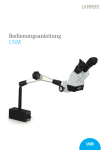
19740 Tablet PC Halter
- Flexibel und stabil! Ihr Tablet wird wunderbar in Szene gesetzt.
- Die Halterung garantiert eine effektive und sichere Montage von
- Tablet-PCs von 6 bis 10,1" Bildschirmgröße
- Übergreifende Klemmbacken mit integrierter Moosgummiauflage sorgen für
- sicheren Halt, eliminieren Vibrationsgeräusche und schützen das Tabletgehäuse
- Gleichermaßen geeignet für Bühne, Heim und Studio
- Mit großzügig dimensionierter Klammer für sicheren Halt an Rohren von ø 11 - 30 mm
- Mit Verstellmöglichkeiten die keine Wünsche offenlassen:
- Tabletgröße, Neigungswinkel, Ausrichtung, Hoch/Querformat: alles flexibel einstellbar
Vielen Dank, dass Sie sich für dieses Produkt entschieden haben. Diese Anleitung informiert
Sie über alle wichtigen Schritte bei Aufbau und Handhabung. Wir empfehlen, sie auch für den
späteren Gebrauch aufzubewahren.
SICHERHEITSHINWEISE
- geeignete Stative verwenden - das setzt voraus: Standfestigkeit, Tragkraft sowie Rohrø 11-30 mm
- z.B. K&M-Stative 118/1, 11888, 11889, 199, 200, 21020, 21090, 210/6, 210/8 etc.
- das Tablet sorgfältig in der Halterung befestigen und auf sicheren Sitz prüfen
- Halterung umsichtig handhaben; v.a. bei Änderungen der Einstellungen
- (Neigung, Format und Ausrichtung) ist auf sicheren Halt des Tablets zu achten
AUFSTELLANLEITUNG (A-I)
A STATIV VORBEREITEN
A (s.o.: Sicherheitshinweise)
B BAUGRUPPEN des 19740 ZURECHTLEGEN
B 1 Tablet-Halterung
B 2 Haltearm mit Klammer (für Rohr-ø 30 mm max.)
B 3 Schwenkgelenk
B 4 Flügelschraube mit Gummischeibe
B 5 Sicherungswinkel
C TABLET-HALTERUNG VOREINSTELLEN
Tablet PC
C 6 Stellen Sie sicher, dass der "große Riegel"'
C 6 ausgerastet ist, was an dem 3 mm-Spalt zu
C 6 erkennen ist (s.Abb.)
C 6 Dazu den "großen Riegel" mit etwas Kraft nach
C 6 oben schieben. Das Ausrasten bewirkt ein
C 6 deutlich hörbares Geräusch.
C 7 Oberen Bügel herausziehen:
C 7 das Innenmaß zwischen den Haltebügeln
C 7 sollte ca.10-15 mm kleiner sein als die Höhe bzw.
C 7 Breite des Tablet-PC.
C 8 "Großen Riegel" wieder nach unten schieben
C 8 (auf hörbares Einrastgeräusch achten)
D 19 Flügelschraube von unten durch Bohrung des
D 19 Haltearmes stecken,
D 10 Gummischeibe über Gewinde schieben
D 11 Flügelschraube in Schwenkgelenk eindrehen
D 12 Klammer des Haltearms an Stativrohr halten und
D 12 durch Anziehen der Rändelschraube befestigen.
E SICHERUNGSWINKEL EINSETZEN
E 13 Sicherungswinkel in die entsprechende
E 13 Aussparung des Schwenkgelenks einlegen.
E 13 Und zwar so, dass der seitliche Anschlag
E 13 am Tablet-PC anliegt (13a)
E 14 Wichtig:
E 14 Der Tablet-PC sollte mittig ausgerichtet sein
E 14 (siehe Punkte 28 und 29),
E 14 ggf. Position des Sicherungswinkels korrigieren.
Stativrohr
D HALTEARM MIT SCHWENKGELENK VERBINDEN
19740 Tablet PC Halter
AUFSTELLANLEITUNG (A-I)
Fortsetzung
F TABLET-HALTERUNG BEFESTIGEN
F 15 Tablet-Halterung auf die 4 Haken des
F 15 Schwenkgelenk setzen
F 16 Anschließend die Halterung bis zum
F 16 Anschlag Richtung feste Haltebügel
F 16 schieben (auf hörbares Einrastgeräusch
F 16 achten)
G TABLET-PC IN HALTERUNG EINSETZEN
G 17 "Kleinen" Riegel bis zum Anschlag
G 17 nach oben schieben (Rastgeräusch!)
G 17 - dadurch kann der Arm gegen eine
G 17 Federkraft nach oben bewegt werden
G 18.a Halterung mit einer Hand festhalten...
G 18.b ...Tablet-PC mittig an den oberen
G 18.b Klemmbacken ansetzen und so weit
G 18.b hoch schieben bis der...
G 18.c ...Tablet-PC auch an den untern KlemmG 18.c backen vollends eingelegt werden kann
G 19 die Federkraft des Armes drückt den
G 19 Tablet-PC in die vier Moosgummiauflagen
G 19 der Klemmbacken
G 20 BEACHTE:
G 20 Der Tablet-PC soll am Sicherungswinkel
G 20 anliegen. Je nach Größe des Tablet-PCs
G 20 muss die Position des Sicherungswinkel
G 20 korrigiert werden. Siehe I 25 ,26 & 28, 29.
G 21 "Kleinen Riegel" nun nach unten
G 21 schieben (Rastgeräusch!) - damit sind
G 21 die oberen Klemmbacken wieder arretiert
H TABLET-PC AUS HALTERUNG ENTNEHMEN
H 22 "Kleinen Riegel" wieder nach oben
H 22 schieben - dadurch ist der Auszug entsperrt
H 23 Tablet-PC nehmen und damit oberen
H 23 Haltebügel hochdrücken
H 24 Tablet-PC unten herausklappen und
H 24 entnehmen
I DEMONTAGE (Abb.re.)
I (z.B. bei Anpassung des Sicherungwinkels 5)
I 25 Verriegelung zwischen Tablet-Halterung
I 25 und Schwenkgelenk lösen:
I 25.a Hebel nach unten drücken und halten
I 25.b Tablet-Halterung bis zum Anschlag
I 25.b ca.6 mm nach oben schieben
I 25.c Tablet-Halterung abheben
I 26 Sicherungswinkel entnehmen
I 27 Bei Bedarf kann durch Entfernen der FlügelI 27 schraube auch der Arm vom Schwenkgelenk
I 27 getrennt werden
I DEMONTAGE
19740 Tablet PC Halter
Drehpunkt/Mittelpunkt:
BENUTZERHINWEISE
- des Halters,
- des Tablet PCs
TABLET-HALTER ANPASSEN
Dazu muss das Tablet aus der Halterung genommen werden
Passend für Tablet-PCs von 6 bis 10,1" Bildschirmgröße
Maßnahmen für korrekten und sicheren Halt sind:
- Vorspannung des Haltebügels richtig einstellen (C 6-8)
28 Tablet im Halter mittig und ausbalanciert positionieren
29 Der Sicherungswinkel sollte stets am Tablet anliegen
29 und muß sich als zusätzliche Sicherung unten befinden,
29 wenn das Tablet hochkant eingestellt ist!
30 Die weichen Moosgummiauflagen sind äußerst schonend
30 für die Oberfläche des Tablet-PC und wirken zusätzlich
30 rutschhemmend
31 Die oberen Klemmbacken können in der Breite
31 verschoben werden, z.B. um Anschlüsse zugänglich
31 zu machen.
31 Prinzipiell jedoch, sollten diese Bügel so weit wie
31 möglich auseinander stehen.
Das Einlegen des Tablets ist unter G beschrieben.
ABMESSUNGEN
FUNKTIONEN
EINSTELLUNGEN (J-N)
im Überblick
&
Schritt für Schritt
Ausrichtung:
Tablet Halter:
Höhe:
120-220 mm
360°
rundum
Ausrichtung:
Haltearm:
Breite:
160-320 mm
360°
rundum
Rohr-ø:
11 bis 30 mm
Format:
hoch-quer
Portrait-Landscape
90°-schwenkbar
K TABLET-HALTER & STATIV
Die Bandbreite reicht von:
- min. 160 bis max. 320 mm in der Breite
- min. 120 bis max. 220 mm in der Höhe
Für Stative mit Rohr-ø von 11 - 30 mm
Das Klappen um 90° ist jederzeit möglich.
Stativrohr
J TABLET-GRÖSSE
Halter voll ausgezogen
19740 Tablet PC Halter
EINSTELLUNGEN
Beim Verstellen der NEIGUNG, des FORMATS
und der AUSRICHTUNG braucht das Tablet
nicht entnommen werden.
L NEIGUNG
Das Tablet kann zwischen senkrechter und
waagerechter Endstellung in jeder Position
fixiert werden.
32 Tablet halten und Flügelmutter etwas lösen
33 Tablet neigen wie gewünscht und
34 Flügelmutter wieder festziehen
M FORMAT
Die Halterung verfügt über eine 90°-Verdrehfunktion.
35 Tablet halten und ins Quer- bzw. Hochformat
35 drehen - oder in die Schräge!
35 Unsichtbare Anschläge in der Halterung
35 begrenzen die Verdrehung
36 BEACHTE: Sicherungswinkel so installieren,
36 dass sich bei vertikaler Ausrichtung des Tablets
36 der Anschlag unten befindet;
36 gegebenenfalls Sicherungswinkel um 180°
36 verdreht in Schwenkgelenk einsetzten
36 (siehe E bzw. I 25, 26)
Querformat
Hochformat
N AUSRICHTUNG
37 Flügelschraube leicht lösen,
37 Tablet-Halterung drehen,
37 Flügelschraube wieder festdrehen
38 Tragarm festhalten, Klemmschraube lösen,
38 Haltearm in gewünschte Richtung drehen,
38 Klemmschraube wieder festziehen
FEHLERSUCHE (F) und BESEITIGUNG (B)
F: Tablet-PC wackelt
F: B: Vorspannung des oberen Haltebügels prüfen, und ggf. korrigieren (C 6-8)
F: B: "Großen Riegel" der Halterung prüfen und falls locker diesen einrasten (C 6-8)
F: Tablet-PC sitzt aussermittig
F: B: Seitenwinkel entsprechend positionieren (E, 28 und 29)
F: Tablet-Halterung wackelt
F: B: Verschraubungen prüfen und ggf. nachziehen (D 11, K 34)
F: B: Einrasten vergessen? Halterung aufsetzen und richtig einrasten (F 15, 16)
F: Tablet-Halterung lässt sich nicht vom Gelenkkörper abziehen
F: B: Erst Hebel drücken, dann Tablet-Halterung entriegeln und abziehen (I 25)
TECHNISCHE DATEN / SPEZIFIKATION
Material
Traglast
Abmessungen
Karton
Gewicht
Schwenkgelenk, Adapter, Griffe: Polyamid (PA-6)
Haltearm, Schrauben, Muttern, Scheiben, Federn: Stahl
Tablet-Halterung: PC-ABS
Klammer: Aluminiumprofil
Tablet-PCs (Abmessungen beachten)
für Tablets: Breite 160-320 mm, Höhe 120-220 mmm
für Rohre: ø 11-30 mm
300 x 75 x 220 mm
netto: 0,77 kg, brutto: 1,0 kg
KÖNIG & MEYER GmbH & Co. KG
Kiesweg 2, 97877 Wertheim, www.k-m.de
19740-000-55 Rev.04 03-80-186-00 1/13
19740 Tablet PC Holder
- Flexible and stable! The ideal presentation for your tablet PC.
- The cradle is an effective and secure mount for tablet PCs with a screen size 6 to 10.1"
- A universal clamping jaw with integrated moss rubber protectors ensures a strong grip, eliminates undesired
- vibration sound problems and protects the tablet housing
- Equally suitable for the stage, home or studio
- A large clamp secures the holder on tubes between ø 11 - ø 30 mm
- The holder is very flexible and can be adjusted to suit a range of tablet sizes,
- tilt, direction, portrait or landscape format
Thank you for choosing this product. These instructions contain information about the installation
and use of the tablet PC holder. We suggest you keep the instructions in a safe place for later use.
SAFETY NOTES
- Use a suitable stand - the stand must be stable, able to accommodate the weight and have a
- tube ø 11-30 mm
- e.g. K&M Stands 118/1 et seq., 11888, 11889, 199, 200, 21020, 21090, 210/6, 210/8, etc.
- Clip the tablet carefully into the holder and check it is held securely
- Manoeuvre the holder with care, particularly when adjusting (tilt, format and direction) and always
- ensure that the tablet is held securely in the cradle
INSTALLATION (A-I)
A PREPARE THE STAND (see Safety Notes above)
B LAY OUT THE COMPONENTS FOR 19740 IN
ORDER
B 1 Tablet cradle
B 2 Supporting arm with clamp (for tubes ø 30 mm max.)
B 3 Swivel joint
B 4 Wing screw with rubber washer
B 5 Guard arm
C PRE-ADJUSTING THE TABLET CRADLE
Tablet PC
C 6 Ensure that the "large latch" is disengaged C 6 look for the 3 mm gap (see Fig.)
C 6 Slide the "large latch" upwards, applying gentle
C 6 strength. There will be an audible click.
C 7 Slide out the upper section:
C 7 The distance between the sides should be
C 7 approx.10-15 mm less than the height or width
C 7 of the tablet PC.
C 8 Slide the "large latch" back down (there should
C 8 be an audible click)
D 19 Insert the wing screw into the bore hole from
D 19 under the supporting arm,
D 10 Position the rubber washer above the thread
D 11 Screw the wind screw into the swivel joint
D 12 Hold the supporting arm clamp on the tube
D 12 and fix by tightening the knurled screw.
E ATTACHING THE GUARD ARM
E 13 Place the guard arm in a suitable groove of the
E 13 swivel joint in such a way that the end sits closely
E 13 with the tablet (13a)
E 14 Important:
E 14 The tablet PC must be aligned centrally
E 14 (see points 28 and 29), if necessary, correct the
E 14 position of the guard arm.
tube
D CONNECTING THE SUPPORT ARM TO THE SWIVEL JOINT
19740 Tablet PC Holder
INSTALLATION (A-I)
Continuation
F ATTACHING THE CRADLE
F 15 Place the cradle on the four hooks of the
F 15 swivel joint
F 16 Slide the cradle to the stop position (you will
F 16 hear a click)
G CLIP THE TABLET PC IN THE CRADLE
G 17 "Move the "small latch" upwards (click!)
G 17 - this allows the arm to be moved upwards
G 17 against a spring tension
G 18.a Hold the cradle firmly with one hand...
G 18.b ...align the tablet PC centrally in the
G 18.b clamping jaw and slide upwards until...
G 18.c ...the tablet PC can also be clipped into
G 18.c the lower side of clamping jaw
G 19 The spring tension of the arm will push the
G 19 tablet PC onto the four moss rubber
G 19 protectors of the clamping jaw
G 20 NOTE:
G 20 The tablet PC should sit neatly with the
G 20 guard arm. The position of the guard arm
G 20 may need to be corrected depending on the
G 20 size of the tablet PC. See I 25 ,26 & 28, 29.
G 21 Now slide the "small latch" down (click!) G 21 the upper jaws are now securely fixed
H REMOVING THE TABLET PC FROM THE CRADLE
H 22 Slide the "small latch" up again - the pull-out
H 22 section is now released
H 23 Hold the tablet PC and use it to push out
H 23 the top side of the cradle
H 24 Unclip the tablet-PC in a downwards motion
H 24 and remove
I DISMANTLING (Fig.re.)
I (e.g. to re-position the guard arm 5)
I 25 Release the lock between the tablet cradle
I 25 and the swivel joint as follows:
I 25.a Press the lever down and hold down
I 25.b Slide the tablet cradle upwards to stop
I 25.b approx. 6 mm
I 25.c Lift the tablet cradle
I 26 Remove the guard arm
I 27 If required, the supporting arm can also be
I 27 separated from the swivel joint by undoing
I 27 the wing screw
I DISMANTLING
19740 Tablet PC Holder
fulcrum/centre point:
USER INSTRUCTIONS
- of the holder,
- of the Tablet PC
ADJUSTING THE TABLET CRADLE
First the tablet must be removed from the cradle
Suitable for tablet PCs with a screen size 6 to 10.1"
Ensure the cradle tension is adjusted correctly so the tablet
is held securely (C 6-8)
28 Position the tablet in the holder centrally and properly
28 balanced
29 The guard arm must always touch the side of the tablet
29 and be under the tablet as additional security when the
29 tablet is positioned in the portrait format!
30 The soft moss rubber protects are effective protectors for
30 the surface of the tablet and also prevent slip
31 The upper clamping jaw can be extended widthways, e.g.
31 to access connections.
31 In general, the jaw should extended as wide as possible.
How to clip in the tablet is described in G.
DIMENSIONS
FUNCTIONS
SETTINGS (J-N)
At a Glance
&
Step by Step
adjustment:
tablet holder:
height:
120-220 mm
360°
all around
adjustment:
supporting arm:
width:
160-320 mm
360°
all around
tube-ø:
11 - 30 mm
format:
portrait-landscape
90°-swivelling
J TABLET SIZES
K TABLET HOLDER & STAND
Range:
- min. 160 to max. 320 mm width
- min. 120 to max. 220 mm height
For stands with a tube diameter of 11 - 30 mm
Can always be flipped 90°.
tube
holder fully extended
19740 Tablet PC Holder
ADJUSTMENT
The tablet does not have to be removed to
adjust the TILT, FORMAT or DIRECTION of
the tablet.
L TILT
The tablet can be fixed in any position between
portrait and landscape format.
32 Hold the tablet and loosen the wing nut
32 slightly
33 Tilt the tablet as required and
34 Re-tighten the wind nut
M FORMAT
The cradle can be moved through 90°.
35 Hold the tablet and turn to portrait or landscape
35 format - or position at an angle!
35 Invisible stops in the cradle prevent the cradle
35 from slipping out of position
36 NOTE: the guard arm must be placed so that
36 when the cradle is in the portrait position it is at
36 the lower edge of the tablet;
36 it may be necessary to turn the guard arm 180°
36 before inserting in the swivel joint (see E bzw.
36 I 25, 26)
Landscape
Portrait
N DIRECTION
37 Loosen the wing screw slightly,
37 turn the tablet cradle,
37 re-tighten the wing screw
38 Hold the supporting arm firmly, loosen the
38 clamping screw, turn the supporting arm to
38 the required direction, re-tighten the
38 clamping screw
FAULT FINDING (F) and SOLUTION (S)
F: Tablet PC wobbles
F: S: Check the tensioning of the upper cradle jaw and if necessary readjust (C 6-8)
F: S: Check the "large latch" of the cradle and if loose click back in place (C 6-8)
F: Tablet PC is not positioned centrally
F: S: Re-position the guard arm (E, 28 and 29)
F: Tablet cradle wobbles
F: S: Check the screw connections and if necessary tighten (D 11, K 34)
F: S: Has the cradle been clipped in correctly? Repeat clipping in procedure (F 15, 16)
F: Tablet cradle cannot be released from the joint component
F: S: Press the lever, then release the tablet and remove (I 25)
TECHNICAL DATA
Materials
Load
Dimensions
Carton
Weight
Swivel joint, adapter, grip: polyamide (PA-6)
Supporting arm, screws, nuts, washers, spring: steel
Tablet cradle: PC-ABS
Clamp: aluminium profile
Tablet-PCs (check dimensions)
For tablets with width 160-320 mm, height 120-220 mm
For tubes: ø 11-30 mm
300 x 75 x 220 mm
net: 0.77 kg, gross: 1.0 kg
KÖNIG & MEYER GmbH & Co. KG
Kiesweg 2, 97877 Wertheim, www.k-m.de
19740-000-55 Rev.04 03-80-186-00 1/13