1
HGV
Extra-large sized housing
EN English - Instructions manual
IT Italiano - Manuale di istruzioni
FR Francais - Manuel d'instructions
DE Deutsch - Bedienungslanleitung
HGV
Extra-large sized housing
EN English - Instructions manual
Contents
ENGLISH
1 About this manual......................................................................................................... 3
1.1 Typographical conventions................................................................................................................................. 3
2 Notes on copyright and information on trademarks................................................. 3
3 Safety rules.................................................................................................................... 3
4 Identification................................................................................................................. 4
4.1 Product description and type designation.................................................................................................... 4
4.2 Product markings.................................................................................................................................................... 4
5 Preparing the product for use...................................................................................... 4
5.1 Contents and unpacking...................................................................................................................................... 4
5.2 Safely disposing of packaging material.......................................................................................................... 4
6 Assembling and installing............................................................................................ 5
6.1 Assembly.................................................................................................................................................................... 5
6.2 Installation................................................................................................................................................................. 5
6.2.1 Opening of the housing....................................................................................................................................................... 5
6.2.1.1 Fastening of the lens and camera to the internal slide................................................................................................................... 5
6.2.1.2 Positioning of the H20 spacer in the inner slide............................................................................................................................... 6
6.2.2 Positioning of the inner slide.............................................................................................................................................. 6
6.2.3 Replacing of the cable gland plate with stainless steel plate supplied............................................................... 6
6.2.4 Fastening of the wiper blade.............................................................................................................................................. 7
6.2.5 Fastening of the small plate with nozzle........................................................................................................................ 7
6.2.6 Closing the housing............................................................................................................................................................... 7
6.3 Wiring.......................................................................................................................................................................... 8
6.3.1 Wiper system............................................................................................................................................................................. 8
6.3.2 Connection of the power supply terminals in input and output.......................................................................... 8
6.3.3 Tamper-switch signalling device....................................................................................................................................... 8
7 Maintaining and cleaning............................................................................................. 9
7.1 Maintaining............................................................................................................................................................... 9
7.1.1 Replacing of the glass in case of damage...................................................................................................................... 9
7.2 Cleaning...................................................................................................................................................................... 9
7.2.1 Window and plastic cover cleaning (PC)........................................................................................................................ 9
8 Disposal of waste materials.......................................................................................... 9
9 Technical specifications................................................................................................ 9
9.1 General........................................................................................................................................................................ 9
9.2 Mechanical................................................................................................................................................................. 9
9.3 Electrical...................................................................................................................................................................10
9.4 Environment............................................................................................................................................................10
9.5 Compliance to........................................................................................................................................................10
10 Technical drawings.................................................................................................... 10
1 About this manual
1.1 Typographical conventions
DANGER!
High level hazard.
Risk of electric shock; disconnect the
power supply before proceeding with any
operation, unless indicated otherwise.
gg
WARNING!
Medium level hazard.
This operation is very important for
the system to function properly. Please
read the procedure described very
carefully and carry it out as instructed.
hh
INFO
Description of system specifications.
We recommend reading this part
carefully in order to understand
the subsequent stages.
jj
The quoted names of products or companies
are trademarks or registered trademarks.
3 Safety rules
The manufacturer declines all responsibility
for any damage caused by an improper use
of the appliances mentioned in this manual.
Furthermore, the manufacturer reserves
the right to modify its contents without
any prior notice. The documentation
contained in this manual has been
collected with great care, the manufacturer,
however, cannot take any liability for
its use. The same thing can be said for
any person or company involved in the
creation and production of this manual.
hh
• The device must be installed only and
exclusively by qualified technical personnel.
• Before any technical work on the appliance,
disconnect the power supply.
• Do not use power supply cables
that seem worn or old.
• Never, under any circumstances, make any
changes or connections that are not shown in
this handbook: improper use of the appliance
can cause serious hazards, risking the safety
of personnel and of the installation.
• Use only original spare parts. Not original
spare parts could cause fire, electrical
discharge or other hazards.
• Before proceeding with installation check the
supplied material to make sure it corresponds
to the order specification by examining the
identification labels ("4.2 Product markings", page 4).
3
EN - English - Instructions manual
Before installing and using this unit,
please read this manual carefully. Be sure
to keep it handy for later reference.
2 Notes on copyright and
information on trademarks
EN - English - Instructions manual
4 Identification
4.1 Product description
and type designation
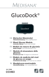
Large-size housing, designed to allow mounting of
the largest "zoom cctv lenses" on the market; for
example PENTAX 55x, FUJINON 60x, PENTAX 18x,
COMPUTAR 30x, COMPUTAR 50x … and many others.
Its water-tightness is assured by the neoprene
rubber gaskets, by 4 M16 cable glands equipped
with relative gaskets and by the stainless steel
screws that guarantee its permanent closure.
It is made up by a shell-cast aluminium base,
epoxypolyester powder painted, and by an
upper casing with integrated sunshield in ABS
PMMA plastic material, colour RAL9002.
The housing is supplied with incorporated
wiper which doesn’t interfere with the field
of vision of the lens-camera installed.
The ideal inner temperature is assured
by enhanced heating and by service
fans for continual air re-circulation.
The assembling and adjustment of the lensescameras are facilitated by the possibility of extracting
the upper casing with integrated sunshield and to
leave them hanging from the sturdy anchoring cable.
5 Preparing the
product for use
Any change that is not expressly
approved by the manufacturer
will invalidate the guarantee.
hh
5.1 Contents and unpacking
When the product is delivered, make sure that
the package is intact and that there are no
signs that it has been dropped or scratched.
If there are obvious signs of damage,
contact the supplier immediately.
Keep the packaging in case you need
to send the product for repairs.
Check the contents to make sure they correspond
with the list of materials as below:
• Housing
• Housing equipment:
• Wiper blade
• Plate with nozzle for wiper
• Stainless steel plate without holes
for cable glands/connectors
• Bracket for mounting lenses and cameras
The HGV housing is ideal for outdoor applications,
as in the case of fire monitoring, public security,
harbours, coastlines, airports, environmental
monitoring and border surveillance.
• Stainless steel washers and screws
4.2 Product markings
• 1/4" screw for lens and camera
See the label attached to the outside of the package.
• Nylon spacers for camera and lens
• Galvanised plate spacer, 20mm-high
• Nylon washers
• Allen key
• Silica gel sachet
• Instructions manual
5.2 Safely disposing of
packaging material
The packaging material can all be recycled.
The installer technician will be responsible for
separating the material for disposal, and in
any case for compliance with the legislation
in force where the device is to be used.
Bear in mind that if the material has to be returned
due to a fault, using the original packaging
for its transport is strongly recommended.
4
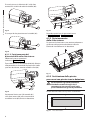
6 Assembling
and installing
Lift the upper casing with integrated sunshield and
leave it hanging to the sturdy anchoring cable.
EN - English - Instructions manual
Only specialised personnel should be
allowed to assemble and install the device.
hh
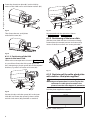
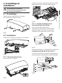
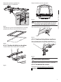
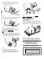
6.1 Assembly
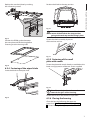
Mount the sunshield to the housing with the 4
screws and washers provided as standard.
Fig. 04
6.2.1.1 Fastening of the lens and
camera to the internal slide
Hook the camera (02) to the lens (01).
Fig. 01
Fasten the L-shaped small aluminium bracket of
the selected length (03) to the camera by means
of the nylon washer (04) and the 1/4" screw (05).
6.2 Installation
01
02
Secure the housing to the bracket with
the 4 screws provided as standard.
03
04
05
Fig. 05
Position the lens on the slide (02) interposing
the plastic spacer (01), and fasten the
whole assembly by means of the nylon
washer (03)and the 1/4" screw (04).
Fig. 02
6.2.1 Opening of the housing
If necessary, use the additional spacers to
correctly position the camera and lens
Undo the 12 captive screws
01
02
03
04
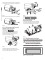
Fig. 06
Fig. 03
5
EN - English - Instructions manual
Fasten the aluminium plate (01) on the slide by
means of the 2 M4 screws and relative washers (02).
01
02
01
03
02
Fig. 07
Fig. 10
Then fasten the two small plates
with the M4 screw (01).
Now proceed with the operations shown
in Fig. 07, page 6 and Fig. 08, page 6.
6.2.2 Positioning of the inner slide
Shift the inner slide with lens and camera already
fastened into the wanted position and secure it by
means of the four washers and screws provided.
01
Fig. 08
6.2.1.2 Positioning of the H20
spacer in the inner slide
Perform the same operations shown in Fig. 05, page 5.
It is possible to fasten the H20 spacer (02) to the
lens, interposing a plastic spacer (01) of the required
thickness, by means of washer and screw (03).
Fig. 11
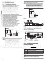
6.2.3 Replacing of the cable gland plate
with stainless steel plate supplied
01
In order to maintain the housing’s IP66
degree of protection it is necessary for the
connector or cable gland inserted in the
plate to have the same degree of protection
hh
02
03
Drill the plate supplied as required.
Fig. 09
120 mm
40 mm
Position the lens with the spacer (01) in the inner
slide (02) and fasten the spacer by means of the
washers and screws (03) provided as standard.
Fig. 12
6
Useful drilling area.
Replace the standard plate by undoing
the 4 fastening screws.
Position the blade in the stop position.
EN - English - Instructions manual
Fig. 16
The correct adjustment must allow the
return of the blade to the stop position
going to the end stop on the casing’s plate.
hh
Fig. 13
Position the EPDM gaskets between
the new plate and the housing before
fastening it to the housing itself.
Fasten the whole assembly by means
of the washer and nut.
Fig. 17
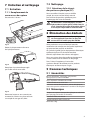
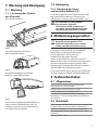
6.2.5 Fastening of the small
plate with nozzle
Fig. 14
6.2.4 Fastening of the wiper blade
Fasten the plate with nozzle already assembled to the
lower casing by means of the two screws supplied
Insert the blade in the wiper shaft.
Fig. 18
To calibrate the jet direct the nozzle
towards the glass of the housing.
jj
Fig. 15
Fasten the nut to fix the nozzle in its position.
6.2.6 Closing the housing
Close the housing following the opposite
procedure ("6.2.1 Opening of the housing", page
5). Fasten with tightening torque of 1,6Nm.
7
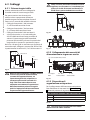
6.3 Wiring
In the 230Vac model, a strap must be
applied between the 3 conductors to
avoid the risk of accidental contacts
between the phase wire and the
accessible conductive part.
gg
EN - English - Instructions manual
6.3.1 Wiper system
This section describes how to connect the
housings equipped with glass wiper system
For these versions it is not necessary to mount
any component inside the casing since the units
are supplied complete with all the elements
necessary, according to the model requested.
• Connect terminal S of clamp J1,
to the mains power phase
• Connect terminal C of clamp J1, to
the mains power neutral.
• Connect terminal P of clamp J1, to a pushbutton which in turn is connected to the
mains power phase, and allows the activation
of the wiper system by keeping it pressed.
By releasing the push-button the wiper
blade will return to the rest position.
Fig. 20
Should a receiver with wiper command be
available, connect terminals SW, PER and COM
respectively to terminals S, P and C of clamp J1.
Fig. 21
J1 Terminal
Phase
Neutral
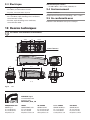
6.3.2 Connection of the power supply
terminals in input and output
J6 - Camera OUT 24Vac/12Vdc
C
S
P
Fig. 19
In the 230Vac model it is necessary to
insert on the supply line, upstream of
the equipment, a unipolar 1 0 main
switch (distance of contacts opening
d>3 mm). This switch must be used as
circuit breaker to the power supply
before carrying out any maintenance
operation or opening of the equipment.
gg
J9 - Tamper
OUT
J10 - OUT
230Vac/24Vac
J7 - IN
230Vac/24Vac
Fig. 22
6.3.3 Tamper-switch signalling device
In order to connect the tamper-switch, refer
to terminal J9 of Fig. 22, page 8, taking the
following indications into account:
tamper-switch connection
COM
Common switch
NC
Normally closed terminal
NO
Normally open terminal
Tab. 01
Operating voltage of switch,
less than 30Vac or 60Vdc.
hh
8
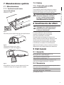
7.2 Cleaning
7.1 Maintaining
7.2.1 Window and plastic
cover cleaning (PC)
7.1.1 Replacing of the glass
in case of damage
Loosen the 5 nuts.
Surface dirt should be rinsed away with water and
then the window cleaned with a neutral soap diluted
with water, or specific products for spectacle lens
cleaning. These should be applied with a soft cloth.
Avoid ethyl alcohol, solvents,
hydrogenated hydrocarbide, strong
acid and alkali. Such products may
irreparably damage the surface.
hh
8 Disposal of waste
materials
Fig. 23
Extract the external glass plate from the inner one.
This symbol mark and recycle system
are applied only to EU countries
and not applied to the countries
in the other area of the world.
nn
Your product is designed and manufactured
with high quality materials and components
which can be recycled and reused.
This symbol means that electrical and electronic
equipment, at their end-of-life, should be disposed
of separately from your household waste.
Fig. 24
Replace the plate with glass in
place of the one damaged.
Please dispose of this equipment at your local
Community waste collection or Recycling centre.
In the European Union there are separate collection
systems for used electrical and electronic products.
9 Technical specifications
9.1 General
Base in aluminium, epoxypolyester powder painting,
RAL9002 colour
Upper body and sunshield in ABS
Stainless steel external screws
Supplied with instruction manual, desiccant bag,
accessories for camera and lens mounting
Fig. 25
Reassemble the whole set in reverse as compared
with the dismantling and re-fasten the 5
nuts with a tightening torque of 1,6Nm.
9.2 Mechanical
Plate with 4xM16 cable glands (in addition a stainless
steel plate is supplied for customized drilling)
Glass window: see drawing
Internal usable area: see drawing
Unit Weight: 9.2kg / 20.2lb
9
EN - English - Instructions manual
7 Maintaining and cleaning
9.3 Electrical
Camera power supply
-- IN 100-240Vac - OUT 12Vdc, 50/60 Hz, 1A
Integrated wiper
-- IN 230Vac, consumption 7W max
9.4 Environment
-- IN 24Vac, consumption 7W max
Indoor / Outdoor
Heater Ton 15°C+/-3°C (59°F +/-5°F) Toff 22°C+/-3°C
(71°F +/-5°F)
Operating temperature with heater: -20°C / +50°C (-4°F
/ +122°F)
-- IN 115/230Vac, fan assisted triple heater,
consumption 150W
9.5 Compliance to
-- IN 24Vac, fan assisted triple heater, consumption 80W
IP66/IP67 according to EN 60529 with cable glands
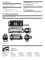
10 Technical drawings
The values are in millimeters.
jj
93
307.2
93
280
275.2
4 CABLE GLANDS M16
256
201
246
736
156
519
117
D
117
C
D
200
108
USEFUL AREA
139
169
USEFUL
AREA
C
150
C-C
D-D
Fig. 26
HGV
VIDEOTEC S.p.A.
www.videotec.com
Printed in Italy
MNVCHGV_0850_EN
HEADQUARTERS ITALY
FRANCE
UK / IRELAND
U.S.A. / CANADA
ASIA PACIFIC
VIDEOTEC S.p.A.
Tel. +39 0445 697411
Fax +39 0445 697414
[email protected]
VIDEOTEC FRANCE S.A.R.L.
Tel. +33 2 32094900
Fax +33 2 32094901
[email protected]
VIDEOTEC UK SALES
Tel. +44 0113 815 0047
Fax +44 0113 815 0047
[email protected]
VIDEOTEC SECURITY, Inc.
Tel. +1 973 5950788
Fax +1 425 6484289
[email protected]
VIDEOTEC (HK) Ltd
Tel. +852 2333 0601
Fax +852 2311 0026
[email protected]
HGV
Custodia stagna extra large
IT Italiano - Manuale di istruzioni
Sommario
ITALIANO
1 Informazioni sul presente manuale............................................................................. 3
1.1 Convenzioni tipografiche..................................................................................................................................... 3
2 Note sul copyright e informazioni sui marchi commerciali....................................... 3
3 Norme di sicurezza........................................................................................................ 3
4 Identificazione............................................................................................................... 4
4.1 Descrizione e designazione del prodotto...................................................................................................... 4
4.2 Marcatura del prodotto......................................................................................................................................... 4
5 Preparazione del prodotto per l'utilizzo..................................................................... 4
5.1 Contenuto e disimballaggio................................................................................................................................ 4
5.2 Smaltimento in sicurezza dei materiali di imballaggio.............................................................................. 4
6 Assemblaggio e installazione....................................................................................... 5
6.1 Assemblaggio........................................................................................................................................................... 5
6.2 Installazione.............................................................................................................................................................. 5
6.2.1 Apertura della custodia........................................................................................................................................................ 5
6.2.1.1 Fissaggio dell’ottica e telecamera alla slitta interna........................................................................................................................ 5
6.2.1.2 Posizionamento del distanziale H20 nella slitta interna................................................................................................................ 6
6.2.2 Posizionamento della slitta interna.................................................................................................................................. 6
6.2.3 Sostituzione della piastra pressacavi con piastra inox in dotazione.................................................................... 6
6.2.4 Fissaggio della spazzola tergicristallo.............................................................................................................................. 7
6.2.5 Fissaggio della piastrina con ugello................................................................................................................................. 7
6.2.6 Chiusura della custodia......................................................................................................................................................... 7
6.3 Cablaggi...................................................................................................................................................................... 8
6.3.1 Sistema tergicristallo ............................................................................................................................................................ 8
6.3.2 Collegamento dei morsetti di alimentazione in ingresso e uscita ....................................................................... 8
6.3.3 Dispositivo di segnalazione antiapertura....................................................................................................................... 8
7 Manutenzione e pulizia................................................................................................ 9
7.1 Manutenzione.......................................................................................................................................................... 9
7.1.1 Sostituzione del vetro in caso di rottura . ...................................................................................................................... 9
7.2 Pulizia........................................................................................................................................................................... 9
7.2.1 Pulizia del vetro e delle parti in plastica (PC)................................................................................................................ 9
8 Smaltimento dei rifiuti.................................................................................................. 9
9 Dati tecnici..................................................................................................................... 9
9.1 Generale..................................................................................................................................................................... 9
9.2 Meccanica.................................................................................................................................................................. 9
9.3 Elettrico.....................................................................................................................................................................10
9.4 Ambiente..................................................................................................................................................................10
9.5 Conformità...............................................................................................................................................................10
10 Disegni tecnici........................................................................................................... 10
1 Informazioni sul
presente manuale
1.1 Convenzioni tipografiche
PERICOLO!
Pericolosità elevata.
Rischio di scosse elettriche. Togliere
l'alimentazione prima di procedere con
le operazioni, salvo diversa indicazione.
gg
ATTENZIONE!
Pericolosità media.
L'operazione è molto importante per
il corretto funzionamento del sistema.
Si prega di leggere attentamente
la procedura indicata e di eseguirla
secondo le modalità previste.
hh
INFO
Descrizione delle caratteristiche del
sistema.
Si consiglia di leggere attentamente
per comprendere le fasi successive.
jj
I nomi di prodotto o di aziende citati sono
marchi commerciali o marchi commerciali
registrati appartenenti alle rispettive società.
IT - Italiano - Manuale di istruzioni
Prima di installare e utilizzare questa unità, leggere
attentamente questo manuale. Conservare questo
manuale a portata di mano come riferimento futuro.
2 Note sul copyright
e informazioni sui
marchi commerciali
3 Norme di sicurezza
Il produttore declina ogni responsabilità
per eventuali danni derivanti da un
uso improprio delle apparecchiature
menzionate in questo manuale. Si
riserva inoltre il diritto di modificarne il
contenuto senza preavviso. Ogni cura è
stata posta nella raccolta e nella verifica
della documentazione contenuta in
questo manuale, tuttavia il produttore
non può assumersi alcuna responsabilità
derivante dall'utilizzo della stessa.
Lo stesso dicasi per ogni persona o
società coinvolta nella creazione e
nella produzione di questo manuale.
hh
• L'installazione e la manutenzione del
dispositivo deve essere eseguita solo
da personale tecnico qualificato.
• Prima di effettuare interventi tecnici
sull'apparecchio togliere l'alimentazione elettrica.
• Non utilizzare cavi di alimentazione con
segni di usura o invecchiamento.
• Non effettuare per nessun motivo
alterazioni o collegamenti non previsti in
questo manuale: l'uso di apparecchi non
idonei può portare a gravi pericoli per la
sicurezza del personale e dell'impianto.
• Utilizzare solo parti di ricambio originali. Pezzi
di ricambio non originali potrebbero causare
incendi, scariche elettriche o altri pericoli.
• Prima di procedere con l'installazione controllare
che il materiale fornito corrisponda alle specifiche
richieste esaminando le etichette di marcatura
("4.2 Marcatura del prodotto", pagina 4).
3
4 Identificazione
IT - Italiano - Manuale di istruzioni
4.1 Descrizione e
designazione del prodotto
Custodia di grandi dimensioni, progettata per
permette l’inserimento tra i più grandi "zoom
cctv lensens" in commercio; ad esempio PENTAX
55x, FUJINON 60x, PENTAX 18x, COMPUTAR
30x, COMPUTAR 50x … e molti altri.
La sua tenuta stagna è mantenuta dalle guarnizioni
in gomma neoprene ,da 4 pressacavi M16 dotati di
relative guarnizioni e dalle viti in acciaio inossidabile
che ne garantiscono una stabile chiusura.
E composta da una base in alluminio ottenuta
per fusione in conchiglia verniciata a polvere
in epossipoliestere, e da un corpo superiore
con tettuccio integrato in materiale plastico
ABS Metacrilato colore RAL9002.
La custodia è fornita con tergicristallo
integrato che non interferisce con il campo
visivo dell’ottica/telecamera installata.
La temperatura interna ideale è assicurata da
un riscaldamento potenziato e da ventilatori di
servizio per un continuo ricircolo dell’aria.
Il montaggio e la regolazione delle ottiche/
telecamere sono facilitati dalla possibilità di estrarre
il corpo superiore con il tettuccio integrato e di
lasciarli appesi al robusto cavo di ancoraggio.
5 Preparazione del
prodotto per l'utilizzo
Qualsiasi cambiamento non
espressamente approvato dal
costruttore fa decadere la garanzia.
hh
5.1 Contenuto e disimballaggio
Alla consegna del prodotto verificare che
l'imballo sia integro e non abbia segni
evidenti di cadute o abrasioni.
In caso di evidenti segni di danno all'imballo
contattare immediatamente il fornitore.
Conservare l'imballo nel caso sia necessario
inviare il prodotto in riparazione.
Controllare che il contenuto sia rispondente
alla lista del materiale sotto indicata:
• Custodia
• Dotazione per custodia:
• Spazzola tergicristallo
• Piastra con ugello per tergicristallo
• Piastra in acciaio inox chiusa per
pressacavi/connettori
• Staffe fissaggio ottiche e telecamere
• Rondelle e viti inox
• Distanziali in nylon per telecamera e ottica
La custodia HGV è l’ideale per applicazioni in esterno,
come il controllo incendi, la sicurezza pubblica, dei
porti, delle coste, degli aeroporti, il monitoraggio
dell’ambiente e la sorveglianza dei confini.
• Distanziale in lamiera zincata alto 20mm
4.2 Marcatura del prodotto
• Chiave a brugola
Vedere l’etichetta posta sull’esterno dell’imballo.
• Rondelle in nylon
• Viti 1/4" per ottica e telecamera
• Sacchetto sali essicanti
• Manuale di istruzioni
5.2 Smaltimento in sicurezza
dei materiali di imballaggio
I materiali d'imballo sono costituiti interamente
da materiale riciclabile. Sarà cura del tecnico
installatore smaltirli secondo le modalità di
raccolta differenziata o comunque secondo
le norme vigenti nel Paese di utilizzo.
Si ricorda comunque che in caso di ritorno di
materiale con malfunzionamenti è consigliato
l'imballaggio originale per il trasporto.
4
6 Assemblaggio e
installazione
Sollevare il corpo superiore con tettuccio integrato
e lasciarlo appeso al robusto cavo di ancoraggio.
L'assemblaggio e l'installazione vanno
eseguiti solo da personale specializzato.
hh
IT - Italiano - Manuale di istruzioni
6.1 Assemblaggio
Fissare il tettuccio alla custodia tramite le 4
viti e le 4 rondelle fornite in dotazione.
Fig. 04
6.2.1.1 Fissaggio dell’ottica e
telecamera alla slitta interna
Agganciare la telecamera (02) all’ottica (01).
Fig. 01
Fissare la staffetta in alluminio a L della
lunghezza prescelta (03) alla telecamera tramite
la rondella in nylon (04) e la vite da 1/4" (05).
6.2 Installazione
01
02
Fissare la custodia alla staffa tramite
le 4 viti fornite in dotazione.
03
04
05
Fig. 05
Posizionare l’ottica sulla slitta (02) interponendo
il distanziale in plastica (01) e fissare il tutto con
la rondella in nylon (03) e la vite da 1/4" (04).
Fig. 02
Se necessario utilizzare i distanziali supplementari per
posizionare in modo corretto telecamera e ottica.
6.2.1 Apertura della custodia
Svitare le 12 viti antiperdita.
01
02
03
04
Fig. 06
Fig. 03
5
01
02
01
03
02
Fig. 07
Fig. 10
Fissare poi le due piastrine con la vite M4 (01).
Procedere quindi con le operazioni come
in Fig. 07, pagina 6 e Fig. 08, pagina 6.
6.2.2 Posizionamento
della slitta interna
01
Far scorrere la slitta interna con ottica e telecamera
già fissate nella posizione desiderata e fissarla
tramite le 4 rondelle e viti in dotazione
Fig. 08
6.2.1.2 Posizionamento del
distanziale H20 nella slitta interna
Effettuare le stesse operazioni
indicate in Fig. 05, pagina 5.
È possibile fissare un distanziale H20 (02) all’ottica
interponendo un distanziale di plastica (01) dello
spessore desiderato, tramite rondella e vite (03).
Fig. 11
6.2.3 Sostituzione della piastra
pressacavi con piastra inox in dotazione
01
02
Per mantenere il grado di protezione
IP66 della custodia bisogna che il
connettore o pressacavo inseriti nella
piastra abbiano tale grado di protezione
hh
03
Fig. 09
Forare secondo necessità la piastra in dotazione
Posizionare l’ottica con il distanziale (01)
sulla slitta interna (02) e fissare tramite le
rondelle e le viti (03) fornite in dotazione.
120 mm
40 mm
IT - Italiano - Manuale di istruzioni
Fissare la piastra in alluminio (01) sulla slitta
tramite le 2 viti M4 e le relative rondelle (02).
Fig. 12
6
Area utile foratura.
Sostituire la piastra standard
svitando le 4 viti di fissaggio
Mettere la spazzola nella posizione di riposo.
IT - Italiano - Manuale di istruzioni
Fig. 16
La regolazione corretta deve
permettere alla spazzola di ritornare
nella posizione di riposo andando in
battuta sulla piastra del corpo.
hh
Fig. 13
Posizionare la guarnizione in EPDM tra la nuova
piastra e la custodia prima di fissarla alla custodia
Fissare il tutto tramite rondella e dado.
Fig. 17
Fig. 14
6.2.4 Fissaggio della
spazzola tergicristallo
6.2.5 Fissaggio della
piastrina con ugello
Fissare la piastra con l’ugello gia assemblato
al corpo inferiore tramite le due viti fornite.
Inserire la spazzola all’albero del tergicristallo
Fig. 18
Per calibrare il getto orientare l’ugello
verso il vetro della custodia.
jj
Fissare il dado per bloccare l'ugello in posizione.
Fig. 15
6.2.6 Chiusura della custodia
Chiudere la custodia seguendo il procedimento
inverso ("6.2.1 Apertura della custodia", pagina 5).
Fissare con coppia di serraggio pari a 1,6Nm.
7
6.3 Cablaggi
Nella versione alimentata a 230Vac occorre
applicare una fascetta tra i 3 conduttori per
evitare il rischio di contatti accidentali tra
filo di fase e parte conduttrice accessibile.
gg
6.3.1 Sistema tergicristallo
IT - Italiano - Manuale di istruzioni
Questa sezione descrive come collegare le
custodie munite di sistema tergicristallo.
Per queste versioni non è necessario
collocare alcun componente all’interno
perché vengono fornite complete di tutto il
necessario, a seconda del modello richiesto.
• Collegare il terminale S, del morsetto
J1, alla fase della tensione di rete.
• Collegare il terminale C, del morsetto
J1, al neutro della tensione di rete.
• Collegare il terminale P, del morsetto J1,
ad un pulsante che, a sua volta collegato
alla fase della tensione di rete, permette di
attivare il sistema tergicristallo tenendolo
premuto. Rilasciando il pulsante la spazzola del
tergicristallo si riporterà in posizione di riposo.
Nel caso si disponga di un ricevitore con funzione di
comando wiper, collegare i morsetti SW, PER e COM
rispettivamente ai terminali S, P e C del morsetto J1.
Fig. 20
Fig. 21
6.3.2 Collegamento dei morsetti di
alimentazione in ingresso e uscita
Morsetto J1
Fase
J6 - Camera OUT 24Vac/12Vdc
Neutro
C
S
P
Fig. 19
Nella versione alimentata a 230Vac occorre
inserire sulla linea di alimentazione,
a monte dell’apparecchiatura, un
interruttore generale unipolare 1 0
(distanza apertura dei contatti d>3
mm). Tale interruttore deve essere
utilizzato come mezzo di separazione
dell’alimentazione prima di eseguire
qualsiasi operazione di manutenzione
o apertura dell’apparecchiatura.
gg
J9 - Tamper
OUT
J10 - OUT
230Vac/24Vac
J7 - IN
230Vac/24Vac
Fig. 22
6.3.3 Dispositivo di
segnalazione antiapertura
Per il collegamento dell’interruttore antiapertura
fare riferimento al morsetto J9 di Fig. 22, pagina
8, tenendo presente le seguenti indicazioni:
Collegamento interruttore antiapertura
COM
Comune interruttore
NC
Morsetto normalmente chiuso
NO
Morsetto normalmente aperto
Tab. 01
Tensione di funzionamento interruttore
minore di 30Vac o 60Vdc.
hh
8
7 Manutenzione e pulizia
7.2 Pulizia
7.1 Manutenzione
7.2.1 Pulizia del vetro e delle
parti in plastica (PC)
Allentare i 5 dadi.
Si consigliano saponi neutri diluiti con acqua o
prodotti specifici per la pulizia delle lenti degli
occhiali con l’utilizzo di un panno morbido.
IT - Italiano - Manuale di istruzioni
7.1.1 Sostituzione del vetro
in caso di rottura
Sono da evitare alcool etilico, solventi,
idrocarburi idrogenati, acidi forti
e alcali. L’utilizzo di detti prodotti
danneggia in modo irreparabile la
superficie delle parti in plastica.
hh
8 Smaltimento dei rifiuti
Questo simbolo e il sistema di
riciclaggio sono validi solo nei paesi
dell'EU e non trovano applicazione
in altri paesi del mondo.
nn
Fig. 23
Estrarre la piastra esterna del vetro da quella interna.
Il vostro prodotto è stato costruito da
materiali e componenti di alta qualità,
che sono riutilizzabili o riciclabili.
Prodotti elettrici ed elettronici che portano
questo simbolo alla fine dell'uso devono essere
smaltiti separatamente dai rifiuti casalinghi.
Vi preghiamo di smaltire questo apparecchio
in un Centro di raccolta o in un'Ecostazione.
Fig. 24
Sostituire la lamiera con il vetro
incollato con quella danneggiata.
Nell'Unione Europea esistono sistemi di raccolta
differenziata per prodotti elettrici ed elettronici.
9 Dati tecnici
9.1 Generale
Base in alluminio, verniciatura a polveri di
epossipoliestere, colore RAL9002
Corpo superiore e tettuccio in ABS
Viteria esterna in acciaio Inox
Fornita con manuale di istruzioni, sacchetto sale,
accessori montaggio telecamera e obiettivo
Fig. 25
9.2 Meccanica
Riassemblare il tutto in maniera opposta e fissare
i 5 dadi con coppia di serraggio pari a 1,6Nm.
Piastra con 4 pressacavi M16 (in dotazione piastra inox
chiusa per forature personalizzate)
Finestra in vetro: vedi disegno
Dimensioni utili interne: vedi disegno
Peso Unitario: 9.2kg
9
9.3 Elettrico
Alimentatore per telecamera
-- IN 100-240Vac - OUT 12Vdc, 50/60 Hz, 1A
Tergicristallo integrato
-- IN 230Vac, consumo 7W max
9.4 Ambiente
-- IN 24Vac, consumo 7W max
Interno / Esterno
Riscaldamento Ton 15°C+/-3°C Toff 22°C+/-3°C
Temperatura d’esercizio con riscaldamento: -20°C / +50°C
-- IN 115/230Vac, triplo riscaldamento assistito da
ventole, consumo 150W
9.5 Conformità
-- IN 24Vac, triplo riscaldamento assistito da ventole,
consumo 80W
IP66/IP67 in accordo con EN 60529 con pressa cavi
10 Disegni tecnici
I valori espressi sono in millimetri.
jj
93
307.2
93
280
275.2
4 PRESSACAVI M16
256
201
246
736
156
519
117
D
117
C
D
200
108
AREA UTILE
139
169
AREA
UTILE
C
150
C-C
D-D
Fig. 26
HGV
VIDEOTEC S.p.A.
www.videotec.com
Printed in Italy
MNVCHGV_0850_IT
HEADQUARTERS ITALY
FRANCE
UK / IRELAND
U.S.A. / CANADA
ASIA PACIFIC
VIDEOTEC S.p.A.
Tel. +39 0445 697411
Fax +39 0445 697414
[email protected]
VIDEOTEC FRANCE S.A.R.L.
Tel. +33 2 32094900
Fax +33 2 32094901
[email protected]
VIDEOTEC UK SALES
Tel. +44 0113 815 0047
Fax +44 0113 815 0047
[email protected]
VIDEOTEC SECURITY, Inc.
Tel. +1 973 5950788
Fax +1 425 6484289
[email protected]
VIDEOTEC (HK) Ltd
Tel. +852 2333 0601
Fax +852 2311 0026
[email protected]
HGV
Le caisson le plus grand de la gamme
FR Français - Manuel d'instructions
Sommaire
FRANÇAIS
1 À propos de ce mode d’emploi..................................................................................... 3
1.1 Conventions typographiques............................................................................................................................. 3
2 Notes sur le copyright et informations sur les marques de commerce..................... 3
3 Normes de securité........................................................................................................ 3
4 Identification................................................................................................................. 4
4.1 Description et désignation du produit............................................................................................................ 4
4.2 Marquage du produit............................................................................................................................................ 4
5 Préparation du produit en vue de l’utilisation............................................................ 4
5.1 Contenu et déballage............................................................................................................................................ 4
5.2 Élimination sans danger des matériaux d’emballage................................................................................ 4
6 Assemblage et installation........................................................................................... 5
6.1 Assemblage............................................................................................................................................................... 5
6.2 Installation................................................................................................................................................................. 5
6.2.1 Ouverture du caisson............................................................................................................................................................. 5
6.2.1.1 Fixation de l’optique et de la caméra à la glissière interne........................................................................................................... 5
6.2.1.2 Positionnement de l’entretoise H20 dans la glissière interne...................................................................................................... 6
6.2.2 Positionnement de la glissière interne............................................................................................................................ 6
6.2.3 Remplacement de la plaque presse-câbles avec la plaque inox fournie............................................................ 6
6.2.4 Fixation du balai essuie-glace............................................................................................................................................ 7
6.2.5 Fixation de la platine avec buse......................................................................................................................................... 7
6.2.6 Fermeture du caisson............................................................................................................................................................ 7
6.3 Câblages..................................................................................................................................................................... 8
6.3.1 Système d’essuie-glace......................................................................................................................................................... 8
6.3.2 Connexion des bornes d’alimentation en entrée et en sortie................................................................................ 8
6.3.3 Dispositif de signalisation anti-ouverture...................................................................................................................... 8
7 Entretien et nettoyage.................................................................................................. 9
7.1 Entretien..................................................................................................................................................................... 9
7.1.1 Remplacement du verre en cas de rupture................................................................................................................... 9
7.2 Nettoyage.................................................................................................................................................................. 9
7.2.1 Entretiens de la vitre et des parties en plastique (PC)............................................................................................... 9
8 Élimination des déchets................................................................................................ 9
9 Données techniques...................................................................................................... 9
9.1 Généralités................................................................................................................................................................. 9
9.2 Mécanique................................................................................................................................................................. 9
9.3 Électrique.................................................................................................................................................................10
9.4 Environnement......................................................................................................................................................10
9.5 En conformité avec ..............................................................................................................................................10
10 Dessins techniques.................................................................................................... 10
1 À propos de ce
mode d’emploi
Avant d’installer et d’utiliser cet appareil,
veuillez lire attentivement ce mode d’emploi.
Conservez-le à portée de main pour pouvoir
vous y reporter en cas de besoin.
DANGER!
Risque élevé.
Risque de choc électrique. Sauf indication
contraire, sectionner l’alimentation
avant de procéder à toute opération.
gg
ATTENTION!
Risque moyen.
Opération extrêmement importante
en vue d’un fonctionnement correct du
système; lire avec attention les opérations
indiquées et s’y conformer rigoureusement.
hh
REMARQUE
Description des caractéristiques du
système.
Il est conseillé de procéder à une
lecture attentive pour une meilleure
compréhension des phases suivantes.
jj
Les noms de produit ou de sociétés cités
sont des marques de commerce ou des
marques de commerce enregistrées.
3 Normes de securité
Le producteur décline toute responsabilité
pour les dommages éventuels dus à une
utilisation non appropriée des appareils
mentionnés dans ce manuel. On réserve
en outre le droit d’en modifier le contenu
sans préavis. La documentation contenue
dans ce manuel a été rassemblée et vérifiée
avec le plus grand soin, cependant, le
producteur ne peut pas s’assumer aucune
responsabilité dérivante de l’emploi de
celle là. La même chose vaut pour chaque
personne ou société impliquées dans la
création et la production de ce manuel.
hh
• L’installation et l’entretien du dispositif
doivent être exclusivement être effectués
par un personnel technique qualifié.
• Sectionner l’alimentation électrique avant
toute intervention technique sur l’appareil.
• Ne pas utiliser de câbles d’alimentation
usés ou endommagés.
• Ne procéder sous aucun prétexte à des
modifications ou des connexions non prévues
dans ce manuel: l’utilisation d’appareils non
adéquats peut comporter des dangers graves
pour la sécurité du personnel et de l’installation.
• Utiliser uniquement des pièces de rechange
d’origine. Les pièces non d’origine peuvent être
source d’incendies, de choc électrique ou autres.
• Avant de procéder à l’installation, contrôler
que le matériel fourni correspond à la
commande et examiner les étiquettes de
marquage ("4.2 Marquage du produit", page 4).
3
FR - Francais - Manuel d'instructions
1.1 Conventions typographiques
2 Notes sur le copyright
et informations sur les
marques de commerce
4 Identification
FR - Francais - Manuel d'instructions
4.1 Description et
désignation du produit
Caisson grandes dimensions projeté pour être
intégré aux plus grands zoom cctv lensens
disponibles dans le commerce, comme par
exemple PENTAX 55x, FUJINON 60x, PENTAX
18x, COMPUTAR 30x, COMPUTAR 50x, etc.,
ainsi qu’à de nombreux autres modèles.
Son étanchéité est assurée par les garnitures
en caoutchouc néoprène, par 4 pressecâbles M16 avec garnitures et par des vis en
acier inox assurant une fermeture fiable.
Comprend une base en fusion d’aluminium –
coquille peinte époxy-polyester, et une structure
supérieure avec toit pare-soleil intégré en matériau
plastique ABS méthacrylate coloris RAL9002.
Un essuie-glace est intégré à la structure
du caisson et n’interfère pas avec le champ
visuel de l’optique/caméra installée.
La température interne idéale est assurée
par un chauffage grande puissance et
des ventilateurs de service permettant
une recirculation constante de l’air.
Le montage et le réglage des optiques/caméras
sont simplifiés grâce à la possibilité d'extraire
la structure supérieure à auvent intégré et de
la pendre au câble d'ancrage très solide.
Le caisson HGV représente la solution parfaite
pour les applications extérieures comme le
contrôle anti-incendie, la sécurité publique
des ports, côtes et aéroports, ainsi que pour la
surveillance de l’environnement et des frontières.
5 Préparation du produit
en vue de l’utilisation
Toute modification non approuvée
expressément par le fabricant entraînera
l’annulation de la garantie.
hh
5.1 Contenu et déballage
Lors de la livraison du produit, vérifier que
l’emballage est en bon état et l’absence de
tout signe évident de chute ou d’abrasion.
En cas de dommages évidents, contacter
immédiatement le fournisseur.
Conserver l’emballage en cas de nécessité
d’expédition du produit pour réparation.
Contrôler que le contenu correspond à la
liste matériel indiquée ci-dessous:
• Caisson
• Équipement pour caisson :
• Balai essuie-glace
• Plaque avec buse pour essuie-glace
• Plaque en acier inox fermée pour
presse-câbles/connecteurs
• Étriers fixation optiques et caméras
• Rondelles et vis en inox
• Entretoises en nylon pour caméra et optique
• Entretoise en tôle galvanisée hauteur 20 mm
• Rondelles en nylon
• Vis 1/4" pour optique et caméra
• Clé six pans
• Sachet sels de déshydratation
4.2 Marquage du produit
• Manuel d'instructions
Voir l’étiquette sur l’extérieur de l’emballage.
5.2 Élimination sans danger
des matériaux d’emballage
Le matériel d’emballage est entièrement composé
de matériaux recyclables. Le technicien chargé de
l’installation est tenu de l’éliminer conformément aux
dispositions en matière de collecte sélective et selon
les normes en vigueur dans le pays d’utilisation.
En cas de dysfonctionnement et de retour
de matériel , il est conseillé d’utiliser
l’emballage original pour le transport.
4
6 Assemblage et
installation
Soulever la structure supérieure avec toit pare-soleilt
intégré et la pendre au robuste câble d’ancrage.
L’assemblage et l’installation
doivent exclusivement être effectués
par un personnel spécialisé.
hh
FR - Francais - Manuel d'instructions
6.1 Assemblage
Fixer le toit pare-soleil au caisson au moyen
des 4 vis et des 4 rondelles fournies.
Fig. 04
6.2.1.1 Fixation de l’optique et de
la caméra à la glissière interne
Fixer la caméra (02) à l’optique (01).
Fixer l’étrier en aluminium en L de la longueur
sélectionnée (03) à la caméra au moyen de la
rondelle en nylon (04) et de la vis de 1/4" (05).
Fig. 01
01
6.2 Installation
02
Fixer le caisson à l’étrier au moyen des 4 vis fournies.
03
04
05
Fig. 05
Positionner l’optique sur la glissière (02) en intercalant
l’entretoise en plastique (01) et fixer le tout avec
la rondelle en nylon (03) et la vis de 1/4" (04).
Fig. 02
Si nécessaire, utiliser les entretoises supplémentaires
pour positionner correctement la caméra et l’optique
6.2.1 Ouverture du caisson
Desserrer les 12 vis captives.
01
02
03
04
Fig. 06
Fig. 03
5
Fixer la plaque en aluminium (01) sur la glissière
au moyen des 2 vis M4 et de leurs rondelles (02).
01
02
03
02
Fig. 07
Fig. 10
Fixer ensuite les deux platines avec la vis M4 (01).
Proceder avec les operations comme
dans Fig. 07, page 6 et Fig. 08, page 6.
6.2.2 Positionnement de
la glissière interne
01
Faire glisser la glissière interne avec l’optique
et la caméra déjà fixées en position et la fixer
avec les quatre rondelles et les vis fournies.
Fig. 08
6.2.1.2 Positionnement de l’entretoise
H20 dans la glissière interne
Effectuer les mêmes operations
indiquées dans Fig. 05, page 5.
Il est possible de fixer une entretoise H20
(02) au système optique en intercalant une
entretoise en plastique (01) de l’épaisseur
requise avec rondelle et vis (03).
Fig. 11
6.2.3 Remplacement de la plaque
presse-câbles avec la plaque inox fournie
01
Pour maintenir le degré de protection IP66
du caisson, le connecteur ou le pressecâble introduits dans la plaque doivent
présenter le même degré de protection
hh
02
03
Percer la plaque fournie selon les nécessités.
Fig. 09
Positionner l’optique avec l’entretoise (01)
dans la glissière interne (02) et fixer l’entretoise
avec les rondelles (03) et les vis fournies.
120 mm
40 mm
FR - Francais - Manuel d'instructions
01
Fig. 12
6
Surface utile de perçage.
Remplacer la plaque standard en
desserrant les 4 vis de fixation.
Placer le balai en position de repos.
FR - Francais - Manuel d'instructions
Fig. 16
Un réglage correct doit permettre au balai
de revenir en position de repos en entrant
en contact avec la plaque de la structure.
hh
Fig. 13
Positionner la garniture en EPDM entre la nouvelle
plaque et le caisson avant de la fixer au caisson.
Fixer l’ensemble avec rondelle et écrou.
Fig. 17
6.2.5 Fixation de la platine avec buse
Fig. 14
Fixer la plaque avec la buse déjà assemblée à la
structure inférieure au moyen des deux vis fournies.
6.2.4 Fixation du balai essuie-glace
Insérer le balai dans l’arbre de l’essuie-glace.
Fig. 18
Pour calibrer le jet orienter la
buse vers la vitre du caisson.
jj
Fixer l'écrous pour fermer la buse dans sa position.
Fig. 15
6.2.6 Fermeture du caisson
Fermer le caisson en repetant au contraire les
operations ("6.2.1 Ouverture du caisson", page
5). Utiliser un couple de serrage de 1,6Nm.
7
6.3 Câblages
Dans la version alimentée à 230Vac, prévoir
un collier entre les 3 conducteurs pour
éviter tout contact accidentel entre le fil de
phase et la partie conductrice et accessible.
gg
6.3.1 Système d’essuie-glace
FR - Francais - Manuel d'instructions
Cette partie décrit le mode de connexion des
caissons équipés de système essuie-glace.
Pour ces versions, il n’est pas nécessaire
d’installer de composants à l’intérieur, car
elles sont fournies équipées de tout le
nécessaire en fonction du modèle requis.
• Connecter l’extrémité S de la borne J1
à la phase de la tension de réseau.
• Connecter l’extrémité C de la borne J1
au neutre de la tension de réseau.
• Connecter l’extrémité P de la borne J1 à un
bouton, relié à son tour à la phase de la tension
de réseau et permettant d’activer le système
essuie-glace en le maintenant enfoncé. Le
relâchement du bouton entraînera le retour du
balai de l’essuie-glace en position de repos.
En cas de récepteur avec fonction de commande
wiper, connecter les bornes SW, PER et COM
aux extrémités S, P et C de la borne J1.
Fig. 20
Fig. 21
6.3.2 Connexion des bornes
d’alimentation en entrée et en sortie
Borne J1
Phase
J6 - Camera OUT 24Vac/12Vdc
Neutre
C
S
P
Fig. 19
Dans la version alimentée à 230Vac,
insérer sur la ligne d’alimentation, en
amont de l’appareil, un interrupteur
général unipolaire 1 0 (distance
ouverture des contacts d>3 mm). Cet
interrupteur doit être utilisé comme
moyen de séparation de l’alimentation
avant d’effectuer toute opération
d’entretien ou d’ouverture de l’appareil.
gg
J9 - Tamper
OUT
J10 - OUT
230Vac/24Vac
J7 - IN
230Vac/24Vac
Fig. 22
6.3.3 Dispositif de signalisation
anti-ouverture
Pour la connexion de l’interrupteur antiouverture, utiliser la borne J9 en Fig. 01, page 5,
en tenant compte des indications suivantes:
connexion interrupteur anti-ouverture
COM
Interrupteur commun
NC
Borne normalement fermée
NO
Borne normalement ouverte
Tab. 01
Tension de fonctionnement interrupteur
inférieure à 30Vac ou 60Vdc.
hh
8
7 Entretien et nettoyage
7.2 Nettoyage
7.1 Entretien
7.2.1 Entretiens de la vitre et
des parties en plastique (PC)
7.1.1 Remplacement du
verre en cas de rupture
Desserrer les 5 écrous
Nous conseillons l’emploi, avec un chiffon
souple, de savons neutres dilués avec de
l’eau ou bien de produits spécifiques pour
le nettoyage des vitres de lunettes.
8 Élimination des déchets
Ce symbole et le système de recyclage
ne sont appliqués que dans les pays UE
et non dans les autres pays du monde.
nn
Fig. 23
Retirer la plaque externe du verre
de la plaque interne.
Votre produit est conçu et fabriqué avec des
matèriels et des composants de qualité supérieure
qui peuvent être recyclés et réutilisés.
Ce symbole signifie que les équipements électriques
et électroniques en fin de vie doivent être
éliminés séparément des ordures ménagères.
Nous vous prions donc de confier cet équipement
à votre Centre local de collecte ou Recyclage.
Fig. 24
Dans l’Union Européenne, il existe des
systèmes sélectifs de collecte pour les produits
électriques et électroniques usagés.
Remplacer la partie endommagée
par la tôle avec le verre collé.
9 Données techniques
9.1 Généralités
Base en aluminium, vernissage avec poudres
époxypolyester, couleur RAL9002
Corps supèrieur et double-toit en ABS
Visserie extérieure en acier inox
Livré avec manuel d’instructions, sachet deshydratant,
accessoires pour l’installation de la caméra et de l’objectif
Fig. 25
Remonter le tout en sens contraire et
remettre les 5 écrous en place utilisant
un couple de serrage de 1,6Nm.
9.2 Mécanique
Plaque avec 4 presse-étoupes M16 (plaque en acièr inox
pour perçage personalisé en dotation)
Fenêtre en verre: voir dessin
Surface intérieure utile: voir dessin
Poids Net: 9.2kg
9
FR - Francais - Manuel d'instructions
On doit éviter: alcool éthylique, solvants,
hydrocarbures hydro-génés, acides forts et
alcali. L’emploi de ce type de produits abîme
d’une façon irréparable la surface traitée.
hh
9.3 Électrique
Alimentation pour camèra
-- IN 100-240Vac - OUT 12Vdc, 50/60 Hz, 1A
Essuie-glace intégré
-- IN 230Vac, consommation 7W max
9.4 Environnement
-- IN 24Vac, consommation 7W max
Intérieur / Extérieur
Chauffage Ton 15°C+/-3°C Toff 22°C+/-3°C
Température d’exercice avec chauffage: -20°C / + 50°C
-- IN 115/230Vac, triple chauffage avec ventilateur,
consommation 150W
9.5 En conformité avec
-- IN 24Vac, triple chauffage avec ventilateur,
consommation 80W
IP66/IP67 selon EN 60529 avec presse-étoupes
10 Dessins techniques
Les valeurs sont entendues en millimètres.
jj
93
307.2
93
280
275.2
4 PRESSE-ÉTOUPES M16
256
201
246
736
156
519
117
D
117
C
D
200
108
SURFACE UTILE
139
169
SURFACE
UTILE
C
150
C-C
D-D
Fig. 26
HGV
VIDEOTEC S.p.A.
www.videotec.com
Printed in Italy
MNVCHGV_0850_FR
HEADQUARTERS ITALY
FRANCE
UK / IRELAND
U.S.A. / CANADA
ASIA PACIFIC
VIDEOTEC S.p.A.
Tel. +39 0445 697411
Fax +39 0445 697414
[email protected]
VIDEOTEC FRANCE S.A.R.L.
Tel. +33 2 32094900
Fax +33 2 32094901
[email protected]
VIDEOTEC UK SALES
Tel. +44 0113 815 0047
Fax +44 0113 815 0047
[email protected]
VIDEOTEC SECURITY, Inc.
Tel. +1 973 5950788
Fax +1 425 6484289
[email protected]
VIDEOTEC (HK) Ltd
Tel. +852 2333 0601
Fax +852 2311 0026
[email protected]
HGV
Das grösste Gehäuse des Lieferprogramms
DE Deutsch - Bedienungslanleitung
Inhaltsverzeichnis
DEUTSCH
1 Allgemeines................................................................................................................... 3
1.1 Schreibweisen.......................................................................................................................................................... 3
2 Anmerkungen zum Copyright und Informationen zu den Handelsmarken............. 3
3 Sichereitsnormen.......................................................................................................... 3
4 Identifizierung............................................................................................................... 4
4.1 Beschreibung und Bezeichnung des Produktes.......................................................................................... 4
4.2 Kennzeichnung des Produkts............................................................................................................................. 4
5 Vorbereitung des Produktes auf den Gebrauch......................................................... 4
5.1 Inhalt und Entfernen der Verpackung............................................................................................................. 4
5.2 Sichere Entsorgung der Verpackungsmaterialien....................................................................................... 4
6 Zusammenbau Und Installation................................................................................... 5
6.1 Zusammenbau......................................................................................................................................................... 5
6.2 Installation................................................................................................................................................................. 5
6.2.1 Öffnung des Gehäuses.......................................................................................................................................................... 5
6.2.1.1 Befestigung der Optik und der Kamera am Innenschlitten.......................................................................................................... 5
6.2.1.2 Positionierung des Abstandhalters H20 im Innenschlitten.......................................................................................................... 6
6.2.2 Positionierung des Innenschlittens.................................................................................................................................. 6
6.2.3 Ersetzung der Kabelhalterplatte durch die gelieferte Edelstahlplatte................................................................ 6
6.2.4 Befestigung des Wischerblattes......................................................................................................................................... 7
6.2.5 Befestigung des Plättchens mit Düse.............................................................................................................................. 7
6.2.6 Schliessung des Gehäuses................................................................................................................................................... 7
6.3 Verkabelungen......................................................................................................................................................... 8
6.3.1 Scheibenwischanlage . ......................................................................................................................................................... 8
6.3.2 Anschluss der Speiseklemmen am Ein- und Ausgang ............................................................................................. 8
6.3.3 Signalvorrichtung zum Schutz vor Öffnung................................................................................................................. 8
7 Wartung und Reinigung................................................................................................ 9
7.1 Wartung...................................................................................................................................................................... 9
7.1.1 Ersetzung der Scheibe bei Glasbruch.............................................................................................................................. 9
7.2 Reinigung................................................................................................................................................................... 9
7.2.1 Reinigung des Glases und der Kunststoffteile (PC).................................................................................................... 9
8 Müllentsorgungsstellen................................................................................................ 9
9 Technische Daten........................................................................................................... 9
9.1 Allgemeines............................................................................................................................................................... 9
9.2 Mechanik.................................................................................................................................................................... 9
9.3 Elektrik.......................................................................................................................................................................10
9.4 Umgebung..............................................................................................................................................................10
9.5 Zertifizierungen.....................................................................................................................................................10
10 Technische Zeichnungen.......................................................................................... 10
1 Allgemeines
Lesen Sie bitte vor dem Installieren und
dem Verwenden dieses Gerätes die
Bedienungsanleitung sorgfältig durch. Bewahren
Sie sie zum späteren Nachschlagen auf.
1.1 Schreibweisen
gg
ACHTUNG!
Mittlere Gefährdung.
Der genannte Vorgang hat große
Bedeutung für den einwandfreien
Betrieb des Systems: es wird
gebeten, sich die Verfahrensweise
anzulesen und zu befolgen.
hh
ANMERKUNG
Beschreibung der Systemmerkmale.
Eine sorgfältige Lektüre wird
empfohlen, um das Verständnis der
folgenden Phasen zu gewährleisten.
jj
Die angeführten Produkt- oder Firmennamen sind
Handelsmarken oder eingetragene Handelsmarken.
3 Sichereitsnormen
Der Hersteller lehnt jede Haftung für
eventuelle Schäden ab, die aufgrund
unsachgemäßer Anwendung der in diesem
Handbuch erwähnten Geräte entstanden
ist. Ferner behält er sich das Recht vor, den
Inhalt ohne Vorkündigung abzuändern.
Die Dokumentation in diesem Handbuch
wurde sorgfältig ausgeführt und überprüft,
dennoch kann der Hersteller keine Haftung
für die Verwendung übernehmen. Dasselbe
gilt für jede Person oder Gesellschaft, die
bei der Schaffung oder Produktion von
diesem Handbuch miteinbezogen ist.
hh
• Die Installation und Wartung der Vorrichtung
ist technischen Fachleuten vorbehalten.
• Vor technischen Eingriffen am Gerät muss die
Stromversorgung unterbrochen werden.
• Es dürfen keine Versorgungskabel mit Verschleißoder Alterungsspuren verwendet werden.
• Unter keinen Umständen dürfen Veränderungen
oder Anschlüsse vorgenommen werden, die
in diesem Handbuch nicht genannt sind: Der
Gebrauch ungeeigneten Geräts kann die Sicherheit
des Personals und der Anlage schwer gefährden.
• Es dürfen nur Original-Ersatzteile verwendet
werden. Nicht originale Ersatzteile können
zu Bränden, elektrischen Entladungen
oder anderen Gefahren führen.
• Vor der Installation ist anhand des
Kennzeichnungsschildes nachzuprüfen, ob das
gelieferte Material die gewünschten Eigenschaften
aufweist ("4.2 Kennzeichnung des Produkts", page 4).
3
DE - Deutsch - Bedienungslanleitung
GEFAHR!
Erhöhte Gefährdung.
Stromschlaggefahr; falls nichts anderes
angegeben, unterbrechen Sie die
Stromversorgung, bevor die beschriebenen
Arbeiten durchgeführt werden.
2 Anmerkungen
zum Copyright und
Informationen zu den
Handelsmarken
4 Identifizierung
DE - Deutsch - Bedienungslanleitung
4.1 Beschreibung und
Bezeichnung des Produktes
5 Vorbereitung
des Produktes auf
den Gebrauch
Überdimensioniertes Gehäuse für die Aufnahme
der größten im Handel erhältlichen "Zoom cctv
lenses"; etwa PENTAX 55x, FUJINON 60x, PENTAX 18x,
COMPUTAR 30x, COMPUTAR 50x … und viele andere.
hh
Dichtungen aus Neoprengummi, 4 Kabelhalter M16
samt Dichtungen und Schrauben aus rostfreiem
Stahl schließen das Gehäuse hermetisch ab.
5.1 Inhalt und Entfernen
der Verpackung
Es besteht aus einer im Kokillengussverfahren
hergestellten und mit Epoxydpolyester
pulverbeschichteten Aluminiumbasis sowie aus
dem oberen Korpus mit integrierter Haube aus dem
Kunststoff ABS PMMA mit der Farbe RAL9002.
Bei der Lieferung des Produktes ist zu prüfen, ob
die Verpackung intakt ist oder offensichtliche
Anzeichen von Stürzen oder Abrieb aufweist.
In das Gehäuse ist ein Scheibenwischer
integriert, der das Sichtfeld der installierten
Optik / Kamera nicht beeinträchtigt.
Die ideale Innentemperatur wird von einer besonders
leistungsstarken Heizung und Hilfsventilatoren
sichergestellt, welche die Luft laufend umwälzen.
Die Montage und Einstellung der Optiken
/ Kameras werden durch die Möglichkeit
erleichtert, den oberen Korpus mit der
integrierten Haube zu entnehmen und an dem
robusten Verankerungskabel wegzuhängen.
Das Gehäuse HGV ist ideal für Anwendungen
im Außenbereich, beispielsweise die
Brandüberwachung, Überwachungsaufgaben
zur Sicherstellung der öffentlichen Sicherheit,
zur Überwachung von Häfen, Küsten, Flughäfen,
der Umwelt und von Grenzlinien.
4.2 Kennzeichnung des Produkts
Siehe das Schild außen auf der Verpackung.
Jede vom Hersteller nicht ausdrücklich
genehmigte Veränderung führt zum
Verfall der Gewährleistungsrechte.
Bei offensichtlichen Schadensspuren
an der Verpackung muss umgehend
der Lieferant verständigt werden.
Bewahren Sie die Verpackung auf für den Fall, dass
das Produkt zur Reparatur eingesendet werden muss.
Prüfen Sie, ob der Inhalt mit der nachstehenden
Materialliste übereinstimmt:
• Gehäuse
• Grundzubehör des Gehäuses:
• Wischerblatt
• Platte mit Scheibenwischerdüse
• Ungelochte Edelstahlplatte für
Kabelhalter / Steckverbinder
• Befestigungsbügel für Optiken und Kameras
• Unterlegscheiben und Schrauben aus Edelstahl
• Abstandhalter aus Nylon für Kamera und Optik
• Abstandhalter aus verzinktem
Blech, Höhe 20mm
• Unterlegscheiben aus Nylon
• Schrauben 1/4" für Optik und Kamera
• Inbusschlüssel
• Beutelchen mit Entfeuchtungssalz
• Bedienungslanleitungen
5.2 Sichere Entsorgung der
Verpackungsmaterialien
Die Verpackungsmaterialien sind vollständig
wiederverwertbar. Es ist Sache des
Installationstechnikers, sie getrennt, auf jeden
Fall aber nach den geltenden Vorschriften
des Anwendungslandes zu entsorgen.
Es wird nochmals empfohlen, mit
Fehlfunktionen behaftetes Material in der
Originalverpackung zurückzusenden.
4
6 Zusammenbau
Und Installation
Den oberen Korpus mit der integrierten Haube anheben
und an das robuste Verankerungskabel hängen.
Zusammenbau und Installation
sind Fachleuten vorbehalten.
hh
6.1 Zusammenbau
Das Sonnenschutzdach mit den 4 Schrauben und
4 Unterlegscheiben am Gehäuse befestigen.
6.2.1.1 Befestigung der Optik und
der Kamera am Innenschlitten
Die Kamera (02) mit der Optik (01) zusammenstecken.
Fig. 01
6.2 Installation
Den kleinen L-Bügel aus Aluminium (03)
(in der vorgewählten Länge) mit der
Unterlegschreibe aus Nylon (04) und der
Schraube 1/4" (05) an der Kamera befestigen.
01
Das Gehäuse mit den 4 Schrauben aus
dem Lieferumfang am Bügel fixieren.
02
03
04
05
Fig. 05
Fig. 02
6.2.1 Öffnung des Gehäuses
Die 12 unverlierbaren Schrauben ausdrehen.
Die Optik auf dem Schlitten (02) positionieren.
Dabei den Abstandhalter aus Plastik zwischenlegen
(01). Das Ganze mit der Unterlegscheibe aus
Nylon (03) und der Schraube 1/4" (04) fixieren.
Falls erforderlich, zur korrekten Positionierung
von Kamera und Optik die zusätzlich
vorhandenen Abstandhalter benutzen.
01
02
03
04
Fig. 03
Fig. 06
5
DE - Deutsch - Bedienungslanleitung
Fig. 04
Die Aluminiumplatte (01) mit den 2 Schrauben
M4 und den zugehörigen Unterlegscheiben
(02) auf dem Schlitten befestigen.
01
02
03
02
Fig. 07
Anschließend die beiden Plättchen mit der Schraube
M4 fixieren, wie in der Abbildung gezeigt (01).
01
Fig. 10
Führen Sie die Bedingungen wie in Fig. 07,
Seite 6 und Fig. 08, Seite 6 weiter aus.
6.2.2 Positionierung des
Innenschlittens
Den Innenschlitten mit der Optik und der Kamera,
beides bereits befestigt, in die gewünschte Position
gleiten lassen und dort mit den vier Unterlegscheiben
und Schrauben aus dem Lieferumfang fixieren.
Fig. 08
6.2.1.2 Positionierung des
Abstandhalters H20 im Innenschlitten
Führen Sie die in Fig. 05, Seite
5 angezeigten Bedingungen aus.
Es sit möglich einen H20 Abstandhalter (02) an der
Optik zu befestigen. Legen Sie einen Abstandhalter
aus Plastik (01) in der gewünschten Dicke mit
Unterlegscheibe und Schraube (03) dazwischen.
Fig. 11
6.2.3 Ersetzung der Kabelhalterplatte
durch die gelieferte Edelstahlplatte
Damit die Schutzart IP66 des Gehäuses
erhalten bleibt, muss auch der
Steckverbinder oder Kabelhalter in der
Platte diese Schutzart aufweisen.
hh
01
02
03
Die mitgelieferte Platte nach Bedarf bohren.
Fig. 09
Die Optik mit dem Abstandhalter (01) im
Innenschlitten (02) positionieren und den
Abstandhalter mit den Unterlegscheiben und
Schrauben aus dem Lieferumfang (03) fixieren.
120 mm
40 mm
DE - Deutsch - Bedienungslanleitung
01
Fig. 12
6
Bohrungs- Nutzfläche.
Die Standardplatte ersetzen, indem man
die 4 Befestigungsschrauben ausdreht.
Das Wischerblatt in Ruhestellung bringen.
DE - Deutsch - Bedienungslanleitung
Fig. 16
Das Wischerblatt ist dann richtig
eingestellt, wenn das Blatt in die
Ruhestellung zurückkehren kann und
dabei an der Korpusplatte anschlägt.
hh
Fig. 13
Die Dichtung aus EPDM zwischen der neuen
Platte und dem Gehäuse positionieren, bevor
Erstere endgültig am Gehäuse fixiert wird.
Alles zusammen mit der Unterlegscheibe
und der Mutter befestigen.
Fig. 17
Fig. 14
6.2.4 Befestigung des Wischerblattes
Das Wischerblatt auf die Welle des
Scheibenwischers setzen.
6.2.5 Befestigung des
Plättchens mit Düse
Die Düsenplatte im zusammengesetzten
Zustand mit den beiden beigefügten
Schrauben am unteren Korpus befestigen.
Fig. 18
Zur Kalibrierung des Strahls die Düse
auf die Gehäusescheibe richten.
jj
Fig. 15
Schrauben die Mutter ein, um die Düse
in die Stellung zu befestigen.
6.2.6 Schliessung des Gehäuses
Machen Sie das Gehäuse mit dem
entgegengesetzten Bedienungsverfahren zu ("6.2.1
Öffnung des Gehäuses", Seite 5). Zur Fixierung ein
Anzugsdrehmoment von 1,6Nm verwenden.
7
6.3 Verkabelungen
In der Ausführung mit 230Vac
Versorgungsspannung muss zwischen den 3
Leitern eine Schelle angebracht werden. So
wird das Risiko versehentlichen Kontaktes
zwischen dem Phasendraht und dem
zugänglichen Teil des Leiters ausgeschaltet.
gg
6.3.1 Scheibenwischanlage
Dieser Abschnitt beschreibt, wie Gehäuse mit
Scheibenwischer angeschlossen werden.
Bei diesen Ausführungen braucht innen keine
Komponente angeschlossen werden, weil
sie im Lieferzustand je nach Modell bereits
mit dem Nötigen ausgestattet sind.
DE - Deutsch - Bedienungslanleitung
Das Anschlussstück S von Klemme J1 an
die Netzspannungsphase anschließen.
Das Anschlussstück C von Klemme J1 an den
Nullleiter der Netzspannungsversorgung anschließen.
Das Anschlussstück P von Klemme J1 an
einen Taster anschließen, der seinerseits
mit der Netzspannungsphase verbunden
ist und bei fortgesetztem Drücken die
Betätigung des Scheibenwischers ermöglicht.
Lässt man den Taster los, bewegt sich das
Wischerblatt wieder in die Ruhestellung.
Falls ein Empfänger mit Wischerbefehlsfunktion
eingesetzt wird, müssen die Klemmen SW,
PER und COM an die Anschlüsse S, P und
C von Klemme J1 gelegt werden.
Fig. 20
Fig. 21
6.3.2 Anschluss der Speiseklemmen
am Ein- und Ausgang
J1 Klemme
Phase
J6 - Camera OUT 24Vac/12Vdc
Neutral
C
S
P
Fig. 19
In der Ausführung mit 230Vac
Versorgungsspannung muss dem Gerät
auf der Speiseleitung ein allpoliger
Hauptschalter 1 0 (Kontaktabstand
d>3 mm) vorgeschaltet werden. Mit
diesem Schalter ist das Gerät vor
Wartungen oder dem Öffnen von der
Stromversorgung zu trennen.
gg
J9 - Tamper
OUT
J10 - OUT
230Vac/24Vac
J7 - IN
230Vac/24Vac
Fig. 22
6.3.3 Signalvorrichtung zum
Schutz vor Öffnung
Zum Anschluss des Öffnungsschutzschalters dient
die Klemme J9 aus Fig. 25, Seite 9. Dabei sind die
folgenden Kennzeichnungen zu beachten:
Anschluss des Öffnungsschutzschalters
COM
Gemeinsamer Schalterdraht
NC
Klemme mit Öffnerkontakt
NO
Klemme mit Schließerkontakt
Tab. 01
Die Schalterbetriebsspannung muss
kleiner als 30Vac oder 60Vdc sein.
hh
8
7 Wartung und Reinigung
7.2 Reinigung
7.1 Wartung
7.2.1 Reinigung des Glases
und der Kunststoffteile (PC)
7.1.1 Ersetzung der Scheibe
bei Glasbruch
Die 5 Muttern lockern.
Es werden empfohlen verwässerte neutrale Seifen
oder spezifische Produkte zur Reinigung der
Brillenlinsen zusammen mit einem weichen Tuch.
Zu vermeiden sind Äthylalkohol,
Lösungsmittel, hydrierte
Kohlenwasserstoffe, starke Säuren
und Alkali. Diese Produkte können die
behandelte Oberfläche beschädigen.
hh
DE - Deutsch - Bedienungslanleitung
8 Müllentsorgungsstellen
Dieses Symbol und das entsprechende
Recycling-System gelten nur für
EULänder und finden in den anderen
Ländern der Welt keine Anwendung.
nn
Fig. 23
Die Außenplatte der Scheibe aus
der Innenplatte nehmen.
Ihr Produkt wurde entworfen und hergestellt
mit qualitativ hochwertigen Materialien
und Komponenten, die recycelt und
wiederverwendet werden können.
Dieses Symbol bedeutet, daß elektrische und
elektronische Geräte am Ende ihrer Nutzungsdauer
von Hausmüll getrennt entsorgt werden sollen.
Bitte entsorgen Sie dieses Gerät bei Ihrer örtlichen
Sammelstelle oder im Recycling Centre.
Fig. 24
Das beschädigte Blech mit Scheibe
durch ein neues Blech ersetzen.
In der Europäischen Union gibt es unterschiedliche
Sammelsysteme für Elektrik- und Elektronikgeräte.
9 Technische Daten
9.1 Allgemeines
Unterteil aus Aluminium, Pulverlackierung mit
Epoxydpolyester, Farbe RAL9002
Oberteil und Sonnenschutzdach aus ABS
Externe Schrauben aus rostfreiem Stahl
Fig. 25
Das Ganze in umgekehrter Reihenfolge wie
oben wieder zusammenbauen, dann die
5 Muttern mit einem Anzugsdrehmoment
von 1,6Nm erneut anziehen.
Im Lieferumfang enthalten Betriebsanleitung,
Beutelchen mit Salz, Montagezubehör für Telekamera
und Objektiv
9.2 Mechanik
Platte mit 4xM16-Kabelschellen (auch eine mitgelieferte
rostfreie Platte für kundenspezifische Bohrungen
Glasfenster: (beziehen Sie sich auf der Zeichnung)
Innere Nutzabmessungen: (beziehen Sie sich auf der
Zeichnung)
Einheitsgewicht: 9.2kg
9
9.3 Elektrik
Kameranetzteil
-- IN 100-240Vac - OUT 12Vdc, 50/60 Hz, 1A
Vorinstallierter Wischer
-- IN 230Vac, Verbrauch 7W max
9.4 Umgebung
-- IN 24Vac, Verbrauch 7W max
Für innere / äußere Installationen
Heizung Ton 15°C+/-3°C Toff 22°C+/-3°C
Betriebstemperatur mit Heizung: -20°C / +50°C
-- IN 115/230Vac, dreifache lüftergestützte Heizung,
Verbrauch 150W
9.5 Zertifizierungen
-- IN 24Vac, dreifache lüftergestützte Heizung,
Verbrauch 80W
IP66/IP67 gemäß EN 60529 mit Kabelschellen
10 Technische Zeichnungen
Maßangabe in Millimeter.
jj
93
307.2
93
280
275.2
4 M16-KABELSHELLEN
256
201
246
736
156
519
117
D
117
C
D
200
108
NUTZFLÄCHE
139
169
NUTZFLÄCHE
C
150
C-C
D-D
Fig. 26
HGV
VIDEOTEC S.p.A.
www.videotec.com
Printed in Italy
MNVCHGV_0850_DE
HEADQUARTERS ITALY
FRANCE
UK / IRELAND
U.S.A. / CANADA
ASIA PACIFIC
VIDEOTEC S.p.A.
Tel. +39 0445 697411
Fax +39 0445 697414
[email protected]
VIDEOTEC FRANCE S.A.R.L.
Tel. +33 2 32094900
Fax +33 2 32094901
[email protected]
VIDEOTEC UK SALES
Tel. +44 0113 815 0047
Fax +44 0113 815 0047
[email protected]
VIDEOTEC SECURITY, Inc.
Tel. +1 973 5950788
Fax +1 425 6484289
[email protected]
VIDEOTEC (HK) Ltd
Tel. +852 2333 0601
Fax +852 2311 0026
[email protected]
VIDEOTEC S.p.A.
www.videotec.com
Printed in Italy
MNVCHGV_0850
HEADQUARTERS ITALY
FRANCE
UK / IRELAND
U.S.A. / CANADA
ASIA PACIFIC
VIDEOTEC S.p.A.
Tel. +39 0445 697411
Fax +39 0445 697414
[email protected]
VIDEOTEC FRANCE S.A.R.L.
Tel. +33 2 32094900
Fax +33 2 32094901
[email protected]
VIDEOTEC UK SALES
Tel. +44 0113 815 0047
Fax +44 0113 815 0047
[email protected]
VIDEOTEC SECURITY, Inc.
Tel. +1 973 5950788
Fax +1 425 6484289
[email protected]
VIDEOTEC (HK) Ltd
Tel. +852 2333 0601
Fax +852 2311 0026
[email protected]