1
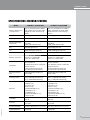
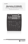
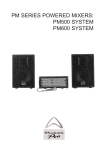
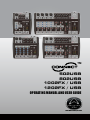
TM
502USB
802USB
1002FX / USB
1202FX / USB
OPERATING MANUAL AND USER GUIDE
www.wharfedalepro.com
OPERATING MANUAL AND USER GUIDE
TABLE OF CONTENTS
IMPORTANT WARNINGS & SAFETY INSTRUCTIONS ....................................................2
INTRODUCTION ................................................................................................................4
ABOUT THE CONNECT MIXERS ......................................................................................4
FEATURES .........................................................................................................................5
USB INTERFACE ...............................................................................................................6
FX INTERFACE ..................................................................................................................6
WALKTHOUGH—CONNECT 502USB ..............................................................................7
WALKTHOUGH—CONNECT 802USB ..............................................................................8
WALKTHOUGH—CONNECT 1002FX/USB (also for 1202) ..............................................9
WALKTHROUGH—REAR PANEL ...................................................................................10
WIRING DIAGRAM ...........................................................................................................10
DIMENSIONAL DRAWING ...............................................................................................11
BLOCK DIAGRAM ............................................................................................................13
SPECIFICATIONS ............................................................................................................17
CONNECT SERIES
IMPORTANT WARNINGS & SAFETY INSTRUCTIONS
1. Read these instructions.
2. Follow all instructions.
3. Keep these instructions.
4. Heed all warnings.
5. Do not use this apparatus near water.
6. Clean only with a dry cloth.
7. Do not block any ventilation openings. Install in accordance with the manufacturer’s
instructions.
8. Do not install near any heat sources such as radiators, heat registers, stoves, or other
apparatus (including amplifiers) that produce heat.
9. Do not defeat the safety purpose of the polarised or grounding-type plug. A polarised plug
has two blades with one wider than the other. A grounding plug has two blades and a third
grounding prong. The wide blade or the third prong is provided for your safety. If the provided
plug does not fit into your outlet, consult an electrician for replacement of the obsolete outlet.
10. Protect the power cord from being walked on or pinched particularly at the plugs, convenience
receptacles, and the point where they exit from the apparatus.
11. Only use attachments/accessories specified by the manufacturer (such as the exclusive supply
adapter, battery etc).
12. Use only with a cart, stand, tripod, bracket, or table specified by the manufacturer, or sold with
the apparatus. When a cart or rack is used, use caution when moving the cart and apparatus
combination to avoid injury from tip-over.
13. Unplug the apparatus during lightning storms or when unused for long periods of time.
14. Refer all servicing to qualified personnel. Servicing is required when the apparatus has been
damaged in any way including but not limited to power supply cord or plug damage, liquid
ingress, foreign objects in the chassis, exposure to rain/moisture or impact damage. In addition
the unit must be serviced when you experience any abnormal operation.
15. CAUTION: These servicing instructions are for use by qualified service personnel only. To
reduce the risk of electric shock, do not attempt to perform any servicing other than that
contained in the operating instructions unless you are qualified to do so. In addition opening the
casing will result in your warranty becoming null and void.
16. Do not install this apparatus in a confined space such as a book case or similar unit. Good
ventilation should be maintained around the apparatus and any vents, air-inlets or fans should
not be obstructed by objects such as paper, table-cloths, curtains etc.
17. WARNING: To reduce the risk of fire or electric shock, do not expose the apparatus to rain or
moisture. The apparatus should not be exposed to dripping or splashing and objects filled with
liquids, such as vases, should not be placed on the apparatus.
18. WARNING: The mains plug is used as a disconnect device, the disconnect device shall remain
readily operable.
OPERATING MANUAL AND USER GUIDE
ATTENTION: RISQUE DE CHOC ELECTRIQUE-NE PAS OUVRIR
19. This lightning flash with arrowhead symbol within an equilateral triangle is intended to alert the
user to the presence of non-insulated “dangerous voltage” within the product’s enclosure that
may be of sufficient magnitude to constitute a risk of electric shock.
Warning: To reduce the risk of electric shock, do not remove the cover (or back) as there are no
user-serviceable parts inside. Refer servicing to qualified personnel.
The exclamation point within an equilateral triangle is intended to alert the user to the presence
of important operating and maintenance instructions in the literature accompanying the
appliance.
20.
This equipment is a Class II or double insulated electrical appliance. It has been designed
in such a way that it does not require a safety connection to electrical earth.
21.
Correct Disposal of this product. This marking indicates that this product should not be
disposed with other household wastes throughout the EU. To prevent possible harm to the
environment or human health from uncontrolled waste disposal, recycle it responsibly to
promote the sustainable reuse of material resources. To return your used device, please use
local return and collection systems or contact the retailer where the product was purchased.
They can take this product for safe environmentally friendly recycling.
CONNECT SERIES
INTRODUCTION
Congratulations on the purchase of your CONNECT series mixer. CONNECT series mixers are
the result of many years of experience in the use, design and manufacture of professional audio
equipment. We take great pride in engineering and building every Wharfedale Pro product and wish
to thank you for entrusting us with your sound.
From the time Gilbert Briggs built his first loudspeaker in 1932, to the present day, Wharfedale have
maintained the same standard of quality in components, workmanship and performance.
Please take the time to read this manual completely in order to ensure that you get the most from
your CONNECT mixer.
ABOUT THE CONNECT MIXERS
The CONNECT mixers from Wharfedale Pro are high quality compact mixers that are suitable for a
wide range of applications.
Professional big mixer features such as Phantom powered, balanced XLR microphone inputs give
you full functionality and great sound in an ultra compact and cost effective package that is ideal for
live sound, home studio recording and fixed installations. The Microphone pre-amplifiers use the
same high quality components and construction methods that are employed in our flagship mixers.
All CONNECT mixers feature an intuitive, ergonomically designed user interface that is excellent for
beginners and professionals alike. Comprehensive connectivity ensures that a CONNECT mixer will
fit into any situation you need.
COMMON FEATURES
• High quality microphone preamplifiers, with switchable global +48V phantom power
• Balanced XLR Mic/Mono inputs with input gain control
• Stereo Channels with Balanced/Unbalanced ¼" TRS Inputs
• Pan/Balance controls for all channels
• Clip LED for all mono channels
• Separate Main Mix and Phones outputs with level controls
• Stereo 4 segment LED meters
• Stereo 1/4” Headphones outputs
• Full duplex 16 bit/48 kHz USB interface, with destination switches
OPERATING MANUAL AND USER GUIDE
CONNECT 502USB FEATURES
• 1 Mono Mic/Line Channel and 2 Stereo Channels
• 2 Band EQs for mono channel
CONNECT 802USB FEATURES
• 2 Mono Mic/Line Channels and 2 Stereo Channels
• 3 Band EQs for all channels
CONNECT 1002FX/USB FEATURES
• 2 Mono Mic/Line Channels and 8 Stereo Line Channels
• 3 Band EQs and switchable high pass filter for all mono channels
• Built-in 56 effects digital FX with LED display
• Control room, FX Send/AUX and Headphones outputs
CONNECT 1202FX/USB FEATURES
• 4 Mono Mic/Line Channels and 8 Stereo Line Channels
• 3 Band EQs and switchable high pass filter for all mono channels
• Built-in 56 effects digital FX with LED display
• Control room, FX Send/AUX and Headphones outputs
CONNECT SERIES
USB INTERFACE
The USB connector enables computers with USB connectivity to interface directly with the
CONNECT mixer for full duplex recording and playback. In recent years the introduction of USB
connectivity has ushered a new appreciation of the capabilities of computer audio, helping to fuse
both digital and analogue and open up endless possibilities for the recording musician.
The internal AD (Analogue to Digital) and DA (Digital to Analogue) converters are 16-bit/48KHz
enabling recording and playback above CD quality, ensuring that recordings that you make with a
CONNECT mixer have outstanding quality.
The CONNECT mixer is fully class compliant and requires no drivers when used with modern
operating systems. Mac OSX, Windows XP, Vista and 7 will require no additional driver software.
Windows WIN7 Installation
Simply choose the device in the following location: Start > Control Panel > Hardware and Sound >
Sound > Manage Audio Devices
Mac OSX Installation
Simply select as an input and output device using the "Audio MIDI Setup" page, you can find this
easily using the spotlight function.
2
USB In
1
3
USB to Phones
4
USB to Main
1. USB Connector for Class Compliant Interfacing with a PC or Mac.
2. Controls the level of the USB inputs.
3. Sends the USB input signal to the headphone outputs.
4. Sends the USB input signal to the main mix bus.
OPERATING MANUAL AND USER GUIDE
FX Interface
You have a choice of 56 different effects, from Reverb to
Flanging to Delay. You can send them to the main mix
outputs.
1
1. Shows the code of the selected effect
2
2. Shows when the FX bus is overloaded
3
3. Turns the FX processor on or off
4. Selects the effect algorithm as listed below the control
4
5. Sends the output of the FX processor to the main mix bus
5
ROOM
r1 Closet, r2 Small ambient room,
r3 Small bathroom, r4 Medium bathroom,
r5 Large bathroom, r6 Small empty room,
r7 Medium empty room, r8 Large empty room.
PLATE
P1 - P5
HALL
h1 Medium hall 1, h2 Medium hall 2,
h3 Medium hall 3, h4 Large hall 1,
h5 Large hall 2, h6 Large hall 3,
h7 Church, h8 Cathedral.
GATED REVERB
g1 - g3
CHORUS
c1 - c4 Chorus 1-4,
c5 - c8 Chorus with reverb 1-4.
FLANGER
F1 - F6 Flanger 1-6,
F7 - F9 Flanger with reverb 1-2.
ROTARY SPEAKER
S1 - S7
DELAY
d1 - d9
CONNECT SERIES
WALKTHOUGH—CONNECT 502USB
Mic 1
502USB
Line In 2/3
Line In 4/5
Main Out
1
Phones
2
L
Line In (Mono)
3
Bal
or
Unbal
Bal
or
Unbal
R
L
(Mono)
Bal
or
Unbal
R
L
18
Balanced
17
R
4
Gain
5
Balance
Clip
+50dB
+30dB
Mic:0
Line:-20
L
R
High
Level
12KHz
6
-
16
+15
Power
Low
+48V
15
80Hz
7
-
USB In
6
USB to Phones
-20
EQ
Balance
L
L
R
L
0
R
USB to Main
R
0
0
Level
Level
9
14
0
Pan
8
Clip
+15
13
-
+15
-
+15
1
-
4/5
10
11
Max
Phones
-
+15
Main Mix
12
1. Balanced XLR input for microphone
2. Balanced/Unbalanced TRS input for line level sources (for the STEREO channel)
3. Balanced/Unbalanced TRS input for line level sources
4. Clip LED lit when the signal is overloaded
5. Gain control for calibrating sources and applying correct gain structure
6. High EQ centred at 12KHz
7. Low EQ centred at 80Hz
8/11. Pan/Balance used to spatially place the channel within the stereo field
9/10. Set the amount of signal to the main mix bus
12. Set the amount of signal to the headphones output
13. Control the master level of the main outputs.
14. Display the realtime level present at the main output bus
15. Indicates +48v phantom power activity
16. Indicates AC power supply
17. To connect headphones
18. Balanced/unbalanced TRS main outputs
OPERATING MANUAL AND USER GUIDE
WALKTHOUGH—CONNECT 802USB
1
2
15
3
14
4
5
6
7
8
13
9
10
12
11
1. Balanced XLR input for microphone
2. Balanced/Unbalanced TRS input for line level sources (for the STEREO channel)
3. Balanced/Unbalanced TRS input for line level sources
4. Clip LED lit when the signal is overloaded
5. Gain control for calibrating sources and applying correct gain structure
6. High EQ centred at 12kHz
7. Mid EQ centred at 1kHz
8. Low EQ centred at 80Hz
9. Pan/Balance used to spatially place the channel within the stereo field
10. Set the amount of signal to the main mix bus
11. Set the amount of signal to the headphones output
12. Controls the master level of the main outputs
13. Displays the realtime level present at the main output bus
14. To connect headphones
15. Balanced/unbalanced TRS main outputs
CONNECT SERIES
WALKTHOUGH—CONNECT 1002FX/USB (also for 1202)
23
22 21
1
20
19
2
3
0
0
0
0
Logic
TM
4
-15
+15
-15
+15
-15
+15
-15
0
5
-15
0
+15
0
0
USB In
+15
USB to Phones
0
0
6
USB to Main
-15
0
+15
0
0
0
7
18
8
0
0
0
0
9
10 11
12
13
14
15
16
17
1. Balanced XLR input for microphone
2. Balanced/Unbalanced TRS input for line level sources
3. Gain control for calibrating sources and applying correct gain structure
4. High EQ centred at 12kHz
5. Mid EQ centred at 1kHz
6. Low EQ centred at 80Hz
7/12. Set the amount of signal to the internal FX processor and AUX output path
8/13. Pan/Balance used to spatially place the channel within the stereo field
9. Clip LED lit when the signal is overloaded
10/14. Sets the amount of signal sent to the main mix bus
11. Activate the high pass filter with 80Hz cut-off point
15. Select the sensitivity for the different level sources.
16. Set the amount of signal to the headphones output
17. Controls the master level of the main outputs
18. Display the realtime level present at the main output bus
19. To connect headphones
20. Send the signal out to the external effector or the external AUX instrument
21. Send the signal out for the control room monitoring
22. Balanced/unbalanced TRS main outputs
23. Balanced/Unbalanced TRS input for line level sources (for the STEREO channel)
10
OPERATING MANUAL AND USER GUIDE
WALKTHROUGH—REAR PANEL
On
Off
On
1
Off
AC17V
2x1000mA 35W
Off
Phantom +48V
AC17V
2x1000mA 35W
On
P1
P2
3
AC Input
Power
P1-P2: 17V~
P3-P2: 17V~
1. Turn the Connect Mixer on or off
2. AC power supply receptacle
CAUTION:
USE THE POWER ADAPTER AUTHORISED BY Wharfedale Pro ONLY!
3. Switch the global +48V phantom power on or off
WIRING DIAGRAM
SIGNAL INPUT
MIC,CD etc.TO CONNECT MIXERS
MIXER
OUTPUT
OUTPUTS FROM GRAPHIC
EQUALISER TO CROSSOVER
INPUT TO
GRAPHIC EQUALISER
SEPARATE
HIGH/MID
AND LOW
OUTPUTS TO
AMPLIFIER(S)
FROM
CROSSOVER
INPUTS TO CROSSOVER
SEPARATE
HIGH/MID
SPEAKER
OUTPUT TO
HIGH/MID
SPEAKER
FROM
AMPLIFIER
INPUTS TO AMPLIFIER(S)
= SIGNAL (SHIELDED) CABLE
= LOUDSPEAKER (NON-SHIELDED) CABLE
11
SEPARATE
LOW
SPEAKER
OUTPUT TO
LOW
FREQUENCY
SPEAKER
FROM
AMPLIFIER
Off
Phantom +48V
P3
2
AC Input
On
CONNECT SERIES
DIMENSIONAL DRAWING
50.9mm
183.8mm
208.0mm
151mm
52.8mm
293.9mm
183.8mm
360.2mm
12
13
+
STEREO INPUT CHANNEL(3-6)
LINE IN
MIC IN
-
MONO INPUT CHANNEL1
48V
GAIN
CLIP LED
LO
EQ
HI
LEVEL
LEVEL
PAN
PAN
L
L
R
R
USB TO MAIN
MASER LEVEL
USB IN
L
R
PHONES
-20dB 0dB 6dB CLIP
MAIN OUT L
MAIN OUT L
MONITOR
USB IN R
USB IN L
CR OUT L
CR OUT R
PHONES
USB OUT R
USB OUT L
USB
OPERATING MANUAL AND USER GUIDE
BLOCK DIAGRAM—CONNECT 502USB
USB TO PHONES
+
STEREO INPUT CHANNEL(3-6)
LINE IN
MIC IN
-
MONO INPUT CHANNEL(1-2)
48V
GAIN
GAIN
GAIN
CLIP LED
LO
LO
LO
MID
MID
EQ
MID
HI
HI
HI
LEVEL
LEVEL
PAN
PAN
L
L
R
R
USB TO MAIN
MASER LEVEL
USB IN
L
PHONES
-20dB 0dB 6dB CLIP
R
MAIN OUT L
MAIN OUT L
MONITOR
USB IN R
USB IN L
CR OUT L
CR OUT R
PHONES
USB OUT R
USB OUT L
USB
CONNECT SERIES
BLOCK DIAGRAM—CONNECT 802USB
14
USB TO PHONES
15
+
LINE IN
LINE IN
STEREO INPUT CHANNEL(3/4-9/10)
LINE IN
MIC IN
-
MONO INPUT CHANNEL(1-2)
48V
+4/-10dB
GAIN
HPF
CLIP LED
LEVEL
LO
EQ
MID
HI
LEVEL
PAN
FX/AUX
PAN
FX/AUX
L
L
R FX/AUX
R FX/AUX
MASER LEVEL
FX SEND TO CONTROL
1
2
FX
3
-20dB 0dB 6dB CLIP
L
R
MAIN OUT L
MAIN OUT L
MONITOR
CR OUT L
CR OUT R
FX Send/AUX
PHONES
USB OUT R
USB OUT L
USB IN R
USB IN L
USB
OPERATING MANUAL AND USER GUIDE
BLOCK DIAGRAM—CONNECT 1002FX/USB
+
LINE IN
LINE IN
STEREO INPUT CHANNEL(5/6-11/12)
LINE IN
MIC IN
-
MONO INPUT CHANNEL(1-4)
48V
+4/-10dB
GAIN
HPF
CLIP LED
LEVEL
LO
EQ
MID
HI
LEVEL
PAN
FX/AUX
PAN
FX/AUX
L
L
R FX/AUX
R FX/AUX
MASER LEVEL
FX SEND TO CONTROL
1
2
FX
3
-20dB 0dB 6dB CLIP
L
R
MAIN OUT L
MAIN OUT L
MONITOR
CR OUT L
CR OUT R
FX Send/AUX
PHONES
USB OUT R
USB OUT L
USB IN R
USB IN L
USB
CONNECT SERIES
BLOCK DIAGRAM—CONNECT 1202FX/USB
16
OPERATING MANUAL AND USER GUIDE
SPECIFICATIONS-502USB/802USB
Model
CONNECT 802USB
Maximum Balanced
Output Level
(1%T.H.D. at 1kHz )
Main 1/4" Jack Balanced out +21dBu
+/-1dBu
Headphones output 150mw +/-5mw @
32ohms
Main 1/4" Jack Balanced out +21dBu
+/-1dBu
Headphones output 150mw +/-5mw @
32ohms
THD+N
<0.025% @ + 14dBu +/-0.5dBu
<0.025% @ + 14dBu +/-0.5dBu
Frequency Response
20Hz~20kHz +/-2dB
20Hz~20kHz +/-2dB
Hum and Noise 20Hz20Khz(150R)
-127dBu +/-5dBu Mic Pre Equivalent
Input Noise
-85dBu +/-5dBu Residual Noise
-127dBu +/-5dBu Mic Pre Equivalent
Input Noise
-85dBu +/-5dBu Residual Noise
S/N
>78dB+-5dB @ pot max
>78dB+-5dB @ pot max
FFT
< -62dBv+/-5dBv @ gain pot max
< -62dBv+/-5dBv @ gain pot max
CMRR
62dB+/-5dB @ 1kHz
62dB+/-5dB @ 1kHz
Maximum Input Level
Mic: +4dBu +/-1dBu
Stereo Line: +21dBu +/-1dBu
Mic: +4dBu +/-1dBu
Stereo Line: +21dBu +/-1dBu
Mic: Balanced 6Kohms, Unbalanced
3Kohms +/-200ohms
Mic: Balanced 6Kohms, Unbalanced
3Kohms +/-200ohms
Line: Balanced 22Kohms, Unbalanced
11 Kohms +/-2kohms
Line: Balanced 22Kohms, Unbalanced
11 Kohms +/-2kohms
All other Unbalanced outputs:60
ohms,Balanced outputs: 120ohms
All other Unbalanced outputs:60
ohms,Balanced outputs: 120ohms
Mono Input Channel
Gain
50dB Variable MIC(0~50dB) Line(20dB~+30dB)
50dB Variable MIC(0~50dB) Line(20dB~+30dB)
Input Channel EQ
High (+/-15dB)+/-1.5dB 12kHz Shelving
Low (+/-15dB)+/-1.5dB 80Hz Shelving
High (+/-15dB)+/-1.5dB 12kHz Shelving
Mid (+/-15dB)+/-1.5dB 1kHz Shelving
Low (+/-15dB)+/-1.5dB 80Hz Shelving
Level Meter
4-Segment LEDx2 (output of +4dB = 0)
Main L/R
4-Segment LEDx2 (output of +4dB = 0)
Main L/R
120V, 60Hz; 220V, 50Hz; 230V, 50Hz;
240V, 50Hz
120V, 60Hz; 220V, 50Hz; 230V, 50Hz;
240V, 50Hz
Dimensions (H x W x D)
50.9*151*183.8 mm (2.0*5.9*7.2 in.)
50.9*208*183.8 mm (2.0*8.2*7.2 in.)
Weight (Net/Gross)
0.64kg /1.62kg
0.92kg /1.9kg
Impedances
AC POWER
17
CONNECT 502USB
CONNECT SERIES
SPECIFICATIONS-1002USB/1202USB
Model
CONNECT 1002FX/USB
CONNECT 1202FX/USB
Maximum Output Level
(1%THD at 1kHz )
Main 1/4" Jack Balanced out +26dBu ±
1dBu, Unbalanced out +21dBu ±1dBu
Headphones output 150mw±5mw @
32ohms
Main 1/4" Jack Balanced out +26dBu ±
1dBu, Unbalanced out +21dBu ±1dBu
Headphones output 150mw±5mw @
32ohms
THD+N
<0.019% @ + 14dBu ±0.5dBu
<0.025% @ + 14dBu ±0.5dBu
Frequency Response
20Hz~20kHz±1dB
20Hz~20kHz±1dB
Hum and Noise 20Hz20Khz(150R)
-127dBu ±5dBu Mic Pre Equivalent
Input Noise
-85dBu ±5dBu Residual Noise
-127dBu ±5dBu Mic Pre Equivalent
Input Noise
-85dBu ±5dBu Residual Noise
S/N
82dB ±5dB @ fader max
78dB ±5dB @ fader max
FFT
-62dBv ±5dBv @ gain fader max
-62dBv ±5dBv @ gain fader max
CMRR
60dB±5dB @ 1kHz
62dB±5dB @ 1kHz
Maximum Input Level
Mic: +4dBu ±1dBu
Channel Line: +25dBu±1dBu
Stereo Line: +25dBu ±1dBu
Mic: +4dBu ±1dBu
Channel Line: +25dBu±1dBu
Stereo Line: +25dBu ±1dBu
Mic: Balanced 6 Kohms, Unbalanced
3Kohms ±500ohms
Mic: Balanced 6 Kohms, Unbalanced
3Kohms ±500ohms
Line: Balanced 44 Kohms, Unbalanced
22Kohms ±2kohms
Line: Balanced 44 Kohms, Unbalanced
22Kohms ±2kohms
All other Unbalanced outputs:100
ohms,Balanced outputs: 200ohms
All other Unbalanced outputs:100
ohms,Balanced outputs: 200ohms
Mono Input Channel
Gain
50dB Variable MIC(0~50dB) Line(20dB~+30dB)
50dB Variable MIC(0~50dB) Line(20dB~+30dB)
Input Channel EQ
High (+/-15dB)±2dB 12kHz Shelving
Mid (+/-15dB)±2dB 1kHz Shelving
Low (+/-15dB)±2dB 80Hz Shelving
High (+/-15dB)±2dB 12kHz Shelving
Mid (+/-15dB)±2dB 1kHz Shelving
Low (+/-15dB)±2dB 80Hz Shelving
56 effects:
1.(ROOM=r1-r8);
2.(PLATE=P1-P5);
3.(HALL=h1-h8);
4.(GATED REVERB=g1-g3);
5.(CHORUS=c1-c8)
6.(FLANGRE=f1-f8);
7.(ROTARY SPEAKER=s1-s7);
8.(DELAY=d1-d9).
56 effects:
1.(ROOM=r1-r8);
2.(PLATE=P1-P5);
3.(HALL=h1-h8);
4.(GATED REVERB=g1-g3);
5.(CHORUS=c1-c8)
6.(FLANGRE=f1-f8);
7.(ROTARY SPEAKER=s1-s7);
8.(DELAY=d1-d9).
Level Meter
4-Segment LEDx2 (output of +4dBu = 0)
Main L/R
4-Segment LEDx2 (output of +4dBu = 0)
Main L/R
AC Power
120V, 60Hz; 220V, 50Hz; 230V, 50Hz;
240V, 50Hz
120V, 60Hz; 220V, 50Hz; 230V, 50Hz;
240V, 50Hz
Dimensions(HxWxD)
52.8*293.9*183.8mm (2.1*11 .6*7.3 in.)
52.8*360.2*183.8mm (2.1*14.2*7.3 in.)
Weights(Net/Gross)
1.37kg/3.0kg
1.69kg/3.3kg
Impedances
Effect Out
Ver: A01 2014.5
18
WHARFEDALE PRO LIMITED WARRANTY
Wharfedale Pro Connect Series products are warranted of manufacturing or material defects for
a period of one year from the original date of purchase. In the event of malfunction, contact your
authorized Wharfedale Pro dealer or distributor for information.
*Be aware that warranty details may differ from country to country. Contact your dealers or
distributor for information. These terms do not infringe your statutory rights.
Wharfedale Professional
IAG House, 13/14 Glebe Road, Huntingdon, Cambridgeshire, PE29 7DL, UK
www.wharfedalepro.com
Wharfedale Professional reserves the right to alter or improve specifications without notice.
All rights reserved © 2014 Wharfedale Pro. Wharfedale Pro is a member of the IAG Group.