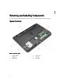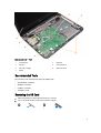
1
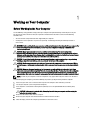
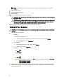
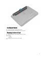
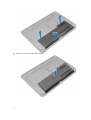
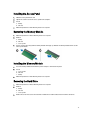
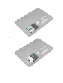
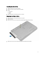
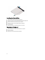
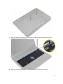
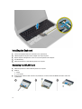
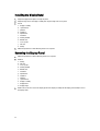
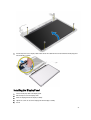
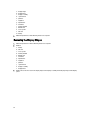
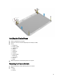
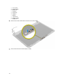
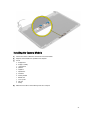
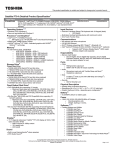
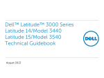
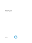
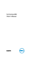
Dell Latitude 3440
Owner's Manual
Regulatory Model: P37G
Regulatory Type: P37G004
Notes, Cautions, and Warnings
NOTE: A NOTE indicates important information that helps you make better use of your computer.
CAUTION: A CAUTION indicates either potential damage to hardware or loss of data and tells you how to avoid the
problem.
WARNING: A WARNING indicates a potential for property damage, personal injury, or death.
Copyright © 2014 Dell Inc. All rights reserved. This product is protected by U.S. and international copyright and intellectual property
laws. Dell™ and the Dell logo are trademarks of Dell Inc. in the United States and/or other jurisdictions. All other marks and names
mentioned herein may be trademarks of their respective companies.
2014 - 01
Rev. A01
Contents
1 Working on Your Computer....................................................................................................... 5
Before Working Inside Your Computer.....................................................................................................................5
Turning Off Your Computer....................................................................................................................................... 6
After Working Inside Your Computer........................................................................................................................7
2 Removing and Installing Components..................................................................................... 8
System Overview...................................................................................................................................................... 8
Recommended Tools................................................................................................................................................ 9
Removing the SD Card.............................................................................................................................................. 9
Installing the SD Card............................................................................................................................................. 10
Removing the Battery............................................................................................................................................. 10
Installing the Battery.............................................................................................................................................. 11
Removing the Access Panel................................................................................................................................... 11
Installing the Access Panel.................................................................................................................................... 13
Removing the Memory Module.............................................................................................................................. 13
Installing the Memory Module................................................................................................................................13
Removing the Hard Drive........................................................................................................................................ 13
Installing the Hard Drive......................................................................................................................................... 15
Removing the Optical Drive.................................................................................................................................... 15
Installing the Optical Drive..................................................................................................................................... 16
Removing the Keyboard..........................................................................................................................................16
Installing the Keyboard...........................................................................................................................................18
Removing the WLAN Card...................................................................................................................................... 18
Installing the WLAN Card....................................................................................................................................... 19
Removing the Palmrest...........................................................................................................................................19
Installing the Palmrest............................................................................................................................................ 22
Removing the I/O Board..........................................................................................................................................22
Installing the I/O Board...........................................................................................................................................23
Removing the Coin-Cell Battery..............................................................................................................................23
Installing the Coin-Cell Battery...............................................................................................................................23
Removing the System Board...................................................................................................................................24
Installing the System Board....................................................................................................................................26
Removing the Heatsink Assembly.......................................................................................................................... 26
Installing the Heatsink Assembly............................................................................................................................27
Removing the Speakers.......................................................................................................................................... 27
Installing the Speakers........................................................................................................................................... 28
Removing the Display Assembly.............................................................................................................................29
Installing the Display Assembly..............................................................................................................................30
Removing the Display Bezel................................................................................................................................... 30
Installing the Display Bezel.....................................................................................................................................32
Removing the Display Panel................................................................................................................................... 32
Installing the Display Panel.................................................................................................................................... 33
Removing the Display Hinges................................................................................................................................. 34
Installing the Display Hinges.................................................................................................................................. 35
Removing the Camera Module............................................................................................................................... 35
Installing the Camera Module.................................................................................................................................37
3 System Setup............................................................................................................................. 38
Boot Sequence....................................................................................................................................................... 38
Navigation Keys......................................................................................................................................................38
System Setup Options.............................................................................................................................................39
Updating the BIOS ................................................................................................................................................. 42
System and Setup Password..................................................................................................................................42
Assigning a System Password and Setup Password...................................................................................... 43
Deleting or Changing an Existing System and/or Setup Password..................................................................43
4 Diagnostics.................................................................................................................................45
Enhanced Pre-Boot System Assessment (ePSA) Diagnostics...............................................................................45
Device Status Lights............................................................................................................................................... 45
Battery Status Lights.............................................................................................................................................. 46
5 Specifications............................................................................................................................ 47
6 Contacting Dell.......................................................................................................................... 52
Working on Your Computer
1
Before Working Inside Your Computer
Use the following safety guidelines to help protect your computer from potential damage and to help to ensure your
personal safety. Unless otherwise noted, each procedure included in this document assumes that the following
conditions exist:
•
You have read the safety information that shipped with your computer.
•
A component can be replaced or--if purchased separately--installed by performing the removal procedure in
reverse order.
WARNING: Before working inside your computer, read the safety information that shipped with your computer. For
additional safety best practices information, see the Regulatory Compliance Homepage at www.dell.com/
regulatory_compliance
CAUTION: Many repairs may only be done by a certified service technician. You should only perform
troubleshooting and simple repairs as authorized in your product documentation, or as directed by the online or
telephone service and support team. Damage due to servicing that is not authorized by Dell is not covered by your
warranty. Read and follow the safety instructions that came with the product.
CAUTION: To avoid electrostatic discharge, ground yourself by using a wrist grounding strap or by periodically
touching an unpainted metal surface, such as a connector on the back of the computer.
CAUTION: Handle components and cards with care. Do not touch the components or contacts on a card. Hold a
card by its edges or by its metal mounting bracket. Hold a component such as a processor by its edges, not by its
pins.
CAUTION: When you disconnect a cable, pull on its connector or on its pull-tab, not on the cable itself. Some
cables have connectors with locking tabs; if you are disconnecting this type of cable, press in on the locking tabs
before you disconnect the cable. As you pull connectors apart, keep them evenly aligned to avoid bending any
connector pins. Also, before you connect a cable, ensure that both connectors are correctly oriented and aligned.
NOTE: The color of your computer and certain components may appear differently than shown in this document.
To avoid damaging your computer, perform the following steps before you begin working inside the computer.
1.
Ensure that your work surface is flat and clean to prevent the computer cover from being scratched.
2.
Turn off your computer (see Turning Off Your Computer).
3.
If the computer is connected to a docking device (docked) such as the optional Media Base or Battery Slice,
undock it.
CAUTION: To disconnect a network cable, first unplug the cable from your computer and then unplug the
cable from the network device.
4.
Disconnect all network cables from the computer.
5.
Disconnect your computer and all attached devices from their electrical outlets.
6.
Close the display and turn the computer upside-down on a flat work surface.
5
NOTE: To avoid damaging the system board, you must remove the main battery before you service the
computer.
7.
Remove the main battery.
8.
Turn the computer top-side up.
9.
Open the display.
10. Press the power button to ground the system board.
CAUTION: To guard against electrical shock, always unplug your computer from the electrical outlet before
opening the display.
CAUTION: Before touching anything inside your computer, ground yourself by touching an unpainted metal
surface, such as the metal at the back of the computer. While you work, periodically touch an unpainted
metal surface to dissipate static electricity, which could harm internal components.
11. Remove any installed ExpressCards or Smart Cards from the appropriate slots.
Turning Off Your Computer
CAUTION: To avoid losing data, save and close all open files and exit all open programs before you turn off your
computer.
1.
Shut down the operating system:
•
In Windows 8:
–
–
•
Using a touch-enabled device:
a.
Swipe in from the right edge of the screen, opening the Charms menu and select Settings.
b.
Select the
and then select Shut down
Using a mouse:
a.
Point to upper-right corner of the screen and click Settings.
b.
Click the
and select Shut down.
In Windows 7:
1.
Click Start
.
2.
Click Shut Down.
or
2.
6
1.
Click Start
2.
Click the arrow in the lower-right corner of the Start menu as shown below, and then click Shut Down..
.
Ensure that the computer and all attached devices are turned off. If your computer and attached devices did not
automatically turn off when you shut down your operating system, press and hold the power button for about 4
seconds to turn them off.
After Working Inside Your Computer
After you complete any replacement procedure, ensure you connect any external devices, cards, and cables before
turning on your computer.
CAUTION: To avoid damage to the computer, use only the battery designed for this particular Dell computer. Do
not use batteries designed for other Dell computers.
1.
Connect any external devices, such as a port replicator, battery slice, or media base, and replace any cards, such
as an ExpressCard.
2.
Connect any telephone or network cables to your computer.
CAUTION: To connect a network cable, first plug the cable into the network device and then plug it into the
computer.
3.
Replace the battery.
4.
Connect your computer and all attached devices to their electrical outlets.
5.
Turn on your computer.
7
Removing and Installing Components
This section provides detailed information on how to remove or install the components from your computer.
System Overview
Figure 1. Inside View — Back
1.
memory modules
2.
SD card slot
3.
WLAN card
4.
hard drive
5.
optical drive
6.
battery bay
8
2
Figure 2. Inside view — Front
1.
system board
2.
I/O board
3.
speakers
4.
coin-cell battery
5.
heat sink assembly
6.
power connector
7.
display
Recommended Tools
The procedures in this document may require the following tools:
•
Small flat-blade screwdriver
•
#0 Phillips screwdriver
•
#1 Phillips screwdriver
•
Small plastic scribe
Removing the SD Card
1.
Follow the procedures in Before Working Inside Your Computer.
2.
Press in on the SD memory card to release it from the computer.
9
Installing the SD Card
1.
Push the memory card into the compartment until it clicks into place.
2.
Follow the procedures in After Working Inside Your Computer.
Removing the Battery
1.
Follow the procedures in Before Working Inside Your Computer.
2.
Slide the release latches outwards to unlock the battery.
3.
Lift the battery to remove it from the computer.
10
Installing the Battery
1.
Slide the battery into its slot until it clicks into place.
2.
Follow the procedures in After Working Inside Your Computer.
Removing the Access Panel
1.
Follow the procedures in Before Working Inside Your Computer.
2.
Remove:
a. battery
b. SD card
3.
Remove the screw that secures the access panel.
11
4.
12
Lift the access panel to remove from the computer.
Installing the Access Panel
1.
Slide the access panel into its slot.
2.
Tighten the screw to secure the access panel to the computer.
3.
Install:
a. battery
b. SD card
4.
Follow the procedures in After Working Inside Your Computer.
Removing the Memory Module
1.
Follow the procedures in Before Working Inside Your Computer.
2.
Remove:
a. battery
b. SD card
c. access panel
3.
Pry the securing clips away from the memory module until it pops up. Remove the memory module from its socket
on the system board.
Installing the Memory Module
1.
Insert the memory module into the memory socket and press until it clicks into place.
2.
Install:
a. access panel
b. SD card
c. battery
3.
Follow the procedures in After Working Inside Your Computer.
Removing the Hard Drive
1.
Follow the procedures in Before Working Inside Your Computer.
2.
Remove:
a. battery
b. SD card
c. access panel
3.
Remove the screw that secures the hard drive and slide the hard drive to disconnect it from the connectors.
13
4.
14
Lift the tab to remove it from the computer.
Installing the Hard Drive
1.
Slide the hard drive in to its slot in the computer.
2.
Tighten the screw to secure the hard drive to the computer.
3.
Install:
a. access panel
b. SD card
c. battery
4.
Follow the procedures in After Working Inside Your Computer.
Removing the Optical Drive
1.
Follow the procedures in Before Working Inside Your Computer.
2.
Remove the battery.
3.
Remove the screw that secures the optical drive and slide the optical drive out of the drive bay.
4.
Remove the screw that secures the optical-drive bracket to the optical drive and remove it.
15
Installing the Optical Drive
1.
Place the optical-drive bracket on to the optical drive.
2.
Tighten the screws to secure the optical-drive bracket to the optical drive.
3.
Slide the optical drive into the drive bay in the computer.
4.
Tighten the screw to secure the optical drive to the computer.
5.
Install the battery.
6.
Follow the procedures in After Working Inside Your Computer.
Removing the Keyboard
1.
Follow the procedures in Before Working Inside Your Computer.
2.
Remove the battery.
3.
Remove the screws from the back of the computer.
16
4.
Release the keyboard by pressing the tabs on the palmrest assembly. Slide the keyboard towards the display
assembly to access the keyboard cable.
5.
Disconnect the keyboard cable from the system board and lift it up to remove it from the computer.
17
Installing the Keyboard
1.
Connect the keyboard cable to its connector on the system board.
2.
Slide the keyboard in its place on the computer and snap it into place.
3.
Flip the computer and tighten the screws to secure the keyboard to the computer.
4.
Install the battery.
5.
Follow the procedures in After Working Inside Your Computer.
Removing the WLAN Card
1.
Follow the procedures in Before Working Inside Your Computer.
2.
Remove:
a. battery
b. access panel
3.
18
Disconnect the antennae cables from the card, remove the screw and remove the WLAN card from its slot on the
system board.
Installing the WLAN Card
1.
Insert the WLAN card into its slot.
2.
Press down the WLAN card and tighten the screw to secure the WLAN card to the computer.
3.
Connect the antenna cables to their respective connectors marked on the WLAN card.
4.
Install:
a. access panel
b. battery
5.
Follow the procedures in After Working Inside Your Computer.
Removing the Palmrest
1.
Follow the procedures in Before Working Inside Your Computer.
2.
Remove:
a.
b.
c.
d.
battery
SD card
access panel
keyboard
3.
Remove the screws that secure the palmrest to the computer.
4.
Flip the computer and remove the screws that secure the palmrest to the system board.
19
5.
Disconnect the touchpad and power-button cable from the system board.
6.
Flip the computer and push the hooks inside the battery bay to release the palmrest.
20
7.
Flip the computer and release the tabs on the sides to lift the palmrest from the computer.
21
Installing the Palmrest
1.
Align and press the palmrest on the computer until it snaps into place on all the sides.
2.
Connect the touchpad and power-button cables to the system board.
3.
Tighten the screws to secure the palmrest to the system board.
4.
Flip the computer and tighten the screws to secure the palmrest to the computer.
5.
Install:
a.
b.
c.
d.
6.
keyboard
access panel
SD card
battery
Follow the procedures in After Working Inside Your Computer.
Removing the I/O Board
1.
Follow the procedures in Before Working Inside Your Computer.
2.
Remove:
a.
b.
c.
d.
e.
3.
22
battery
SD card
access panel
keyboard
palmrest
Disconnect the I/O cable, remove the screw that secures the I/O board to the computer, and lift the I/O board to
remove it from the computer.
Installing the I/O Board
1.
Place the I/O board in its slot.
2.
Tighten the screw to secure the I/O board to the computer.
3.
Connect the I/O cable to the I/O board.
4.
Install:
a.
b.
c.
d.
e.
5.
palmrest
keyboard
access panel
SD card
battery
Follow the procedures in After Working Inside Your Computer.
Removing the Coin-Cell Battery
1.
Follow the procedures in Before Working Inside Your Computer.
2.
Remove:
a.
b.
c.
d.
e.
3.
battery
SD card
access panel
keyboard
palmrest
Pry out the coin-cell battery from the system board.
Installing the Coin-Cell Battery
1.
Place the coin-cell battery in its slot.
2.
Install:
a.
b.
c.
d.
e.
3.
palmrest
keyboard
access panel
SD card
battery
Follow the procedures in After Working Inside Your Computer.
23
Removing the System Board
1.
Follow the procedures in Before Working Inside Your Computer.
2.
Remove:
a.
b.
c.
d.
e.
f.
g.
h.
i.
j.
battery
SD card
access panel
memory module
WLAN card
hard drive
optical drive
keyboard
palmrest
coin-cell battery
3.
Peel the tape that secures the display cable to the system board and disconnect the display cable.
4.
Disconnect the following cables:
a. DC-In Port
b. speaker
c. I/O board
24
5.
Remove the screw that secures the system board to the computer and lift the system board from the computer.
25
Installing the System Board
1.
Align the system board in its place on the computer.
2.
Tighten the screw to secure the system board to the computer.
3.
Connect the following cables:
a.
b.
c.
d.
display
DC-In Port
speaker
I/O board
4.
Affix the tape to secure the display cable to the system board.
5.
Install:
a.
b.
c.
d.
e.
f.
g.
h.
i.
j.
6.
coin-cell battery
palmrest
keyboard
optical drive
hard drive
memory module
WLAN card
access panel
SD card
battery
Follow the procedures in After Working Inside Your Computer.
Removing the Heatsink Assembly
1.
Follow the procedures in Before Working Inside Your Computer.
2.
Remove:
a.
b.
c.
d.
e.
f.
g.
h.
i.
j.
battery
SD card
access panel
memory module
WLAN card
hard drive
optical drive
keyboard
palmrest
system board
3.
Flip the system board and place it on a flat surface.
4.
Disconnect fan cable and remove the screws that secure the heatsink assembly to the system board. Lift the
heatsink assembly from the system board.
26
Installing the Heatsink Assembly
1.
Align the heatsink assembly in its place on the system board.
2.
Tighten the screws to secure the heatsink assembly to the system board.
3.
Install:
a.
b.
c.
d.
e.
f.
g.
h.
i.
j.
4.
system board
palmrest
keyboard
optical drive
hard drive
memory module
WLAN card
access panel
SD card
battery
Follow the procedures in After Working Inside Your Computer.
Removing the Speakers
1.
Follow the procedures in Before Working Inside Your Computer.
2.
Remove:
a. battery
27
b.
c.
d.
e.
f.
g.
h.
i.
j.
3.
SD card
access panel
memory module
WLAN card
hard drive
optical drive
keyboard
palmrest
system board
Unroute the speaker cable from its routing channel and lift the speakers from the computer.
Installing the Speakers
1.
Place the speakers on to its slot and route the cables through the channels.
2.
Install:
a.
b.
c.
d.
e.
f.
g.
h.
i.
j.
3.
28
system board
palmrest
keyboard
optical drive
hard drive
memory module
WLAN card
access panel
SD card
battery
Follow the procedures in After Working Inside Your Computer.
Removing the Display Assembly
1.
Follow the procedures in Before Working Inside Your Computer.
2.
Remove:
a. battery
b. SD card
c. access panel
d. memory module
e. WLAN card
f. hard drive
g. optical drive
h. keyboard
i. palmrest
j. system board
3.
Unroute the display and WLAN antenna cables from their routing channels.
4.
Remove the screws that secure the display assembly to the computer.
29
5.
Lift and remove the display assembly from the computer.
Installing the Display Assembly
1.
Place the display assembly on the computer.
2.
Tighten the screws to secure the display assembly.
3.
Route the display and WLAN antenna cables to their channels.
4.
Install:
a.
b.
c.
d.
e.
f.
g.
h.
i.
j.
5.
system board
palmrest
keyboard
optical drive
hard drive
memory module
WLAN card
access panel
SD card
battery
Follow the procedures in After Working Inside Your Computer.
Removing the Display Bezel
1.
Follow the procedures in Before Working Inside Your Computer.
2.
Remove:
a.
b.
c.
d.
e.
f.
g.
h.
i.
j.
k.
3.
30
battery
SD card
access panel
memory module
WLAN card
hard drive
optical drive
keyboard
palmrest
system board
display assembly
Press the hinge covers on the side. Lift and remove the hinge covers from the computer.
4.
Pry the edges of the display bezel. Remove the display bezel from the computer.
31
Installing the Display Bezel
1.
Align the display bezel in place and snap it in place.
2.
Align the hinge covers on display assembly and snap the hinge covers on its place.
3.
Install:
a.
b.
c.
d.
e.
f.
g.
h.
i.
j.
k.
4.
display assembly
system board
palmrest
keyboard
optical drive
hard drive
memory module
WLAN card
access panel
SD card
battery
Follow the procedures in After Working Inside Your Computer.
Removing the Display Panel
1.
Follow the procedures in Before Working Inside Your Computer.
2.
Remove:
a.
b.
c.
d.
e.
f.
g.
h.
i.
j.
k.
l.
m.
3.
32
battery
SD card
access panel
memory module
WLAN card
hard drive
optical drive
keyboard
palmrest
system board
display assembly
display bezel
display hinges
Remove the screws that secure the display panel to the display assembly. Lift the display panel and flip to access
the display cable.
4.
Peel the tape that secures display cable and disconnect the cable from the connector. Remove the display panel
from the display assembly.
Installing the Display Panel
1.
Connect the display cable to the display panel.
2.
Affix the tape to secure the display cable.
3.
Place the display panel on the display assembly.
4.
Tighten the screws to secure the display panel to the display assembly.
5.
Install:
33
a.
b.
c.
d.
e.
f.
g.
h.
i.
j.
k.
l.
m.
6.
display hinges
display bezel
display assembly
system board
palmrest
keyboard
optical drive
hard drive
memory module
WLAN card
access panel
SD card
battery
Follow the procedures in After Working Inside Your Computer.
Removing the Display Hinges
1.
Follow the procedures in Before Working Inside Your Computer.
2.
Remove:
a.
b.
c.
d.
e.
f.
g.
h.
i.
j.
k.
l.
3.
34
battery
SD card
access panel
memory module
WLAN card
hard drive
optical drive
keyboard
palmrest
system board
display assembly
display bezel
Remove the screws that secure the display hinges to the display assembly. Lift the display hinges off the display
panel.
Installing the Display Hinges
1.
Place the display hinges on its place.
2.
Tighten the screws to secure the display hinges to the display assembly.
3.
Install:
a.
b.
c.
d.
e.
f.
g.
h.
i.
j.
k.
l.
4.
display bezel
display assembly
system board
palmrest
keyboard
optical drive
hard drive
memory module
WLAN card
access panel
SD card
battery
Follow the procedures in After Working Inside Your Computer.
Removing the Camera Module
1.
Follow the procedures in Before Working Inside Your Computer.
2.
Remove:
a. battery
b. SD card
35
c.
d.
e.
f.
g.
h.
i.
j.
k.
l.
access panel
memory module
WLAN card
hard drive
optical drive
keyboard
palmrest
system board
display assembly
display bezel
3.
Disconnect the camera cable from the connector on the camera module.
4.
Lift and remove the camera from the display assembly.
36
Installing the Camera Module
1.
Connect the camera cable to the connector on the camera module.
2.
Align the camera module in its position on the computer.
3.
Install:
a.
b.
c.
d.
e.
f.
g.
h.
i.
j.
k.
l.
4.
display bezel
display assembly
system board
palmrest
keyboard
optical drive
hard drive
memory module
WLAN card
access panel
SD card
battery
Follow the instructions in After Working Inside Your Computer.
37
System Setup
3
System Setup enables you to manage your computer hardware and specify BIOS‐level options. From the System Setup,
you can:
•
Change the NVRAM settings after you add or remove hardware
•
View the system hardware configuration
•
Enable or disable integrated devices
•
Set performance and power management thresholds
•
Manage your computer security
Boot Sequence
Boot Sequence allows you to bypass the System Setup‐defined boot device order and boot directly to a specific device
(for example: optical drive or hard drive). During the Power-on Self Test (POST), when the Dell logo appears, you can:
•
Access System Setup by pressing <F2> key
•
Bring up the one-time boot menu by pressing <F12> key
The one-time boot menu displays the devices that you can boot from including the diagnostic option. The boot-menu
options are:
•
Removable Drive (if available)
•
STXXXX Drive
NOTE: XXX denotes the SATA drive number.
•
Optical Drive
•
Diagnostics
NOTE: Choosing Diagnostics, will display the ePSA diagnostics screen.
The boot sequence screen also displays the option to access the System Setup screen.
Navigation Keys
The following table displays the system setup navigation keys.
NOTE: For most of the system setup options, changes that you make are recorded but do not take effect until you
re-start the system.
Table 1. Navigation Keys
Keys
Navigation
Up arrow
Moves to the previous field.
Down arrow
Moves to the next field.
38
Keys
Navigation
<Enter>
Allows you to select a value in the selected field (if applicable) or follow the link in the field.
Spacebar
Expands or collapses a drop‐down list, if applicable.
<Tab>
Moves to the next focus area.
NOTE: For the standard graphics browser only.
<Esc>
Moves to the previous page till you view the main screen. Pressing <Esc> in the main screen
displays a message that prompts you to save any unsaved changes and restarts the system.
<F1>
Displays the System Setup help file.
System Setup Options
NOTE: The system setup options may vary depending on the computer model.
The Main tab lists out the primary hardware features of the computer. The table below defines the function of each
option.
Table 2. Main Options
Option
Description
System Time
Allows you to reset the time
on the computer's internal
clock.
System Date
Allows you to reset the date
on the computer's internal
calendar.
BIOS Version
Displays the BIOS revision.
Product Name
Displays the product name
and the model number.
Service Tag
Displays the service tag of
your computer.
Asset Tag
Displays the asset tag of
your computer (if available).
CPU Type
Displays the type of
processor.
CPU Speed
Displays the speed of the
processor.
CPU ID
Displays the processor ID.
CPU Cache
L1 Cache
Displays the processor L1
cache size.
L2 Cache
Displays the processor L2
cache size.
39
Option
Description
L3 Cache
Displays the processor L3
cache size.
Fixed HDD
Displays the model number
and capacity of the hard
drive.
SATA ODD
Displays the model number
and capacity of the optical
drive.
AC Adapter Type
Displays the type of the AC
adapter.
System Memory
Displays the memory
installed on the computer
Extended Memory
Displays the extended
memory installed on the
computer.
Memory Speed
Displays the memory speed.
The Advanced tab allows you to set various functions that affect the performance of the computer. The table below
defines the function of each option and its default value.
Table 3. Advance Options
Option
Description
Intel SpeedStep
Enables or disables the Intel SpeedStep feature. The
default option is Enabled
Virtualization
Enables or disables the Intel Virtualization feature. The
default option is Enabled
Integrated NIC
Enables or disables the power supply to the on–board
network card. The default option is Enabled
USB Emulation
Enables or disables the USB emulation feature. The
default option is Enabled
USB Wake Support
Allows USB devices to wake-up the computer from
standby. This feature is enabled only when the AC adapter
is connected. The default option is Disabled
SATA Operation
The default SATA controller mode is AHCI.
Adapter Warnings
Enables or disables adapter warnings. The default option
is Enabled
Function Key Behavior
Specifies the behavior of the function key <Fn> . The
default option is Function key first
Battery Health
Specifies the health of the battery.
Miscellaneous Devices
These fields let you enable or disable various on-board
devices.
40
Option
Description
External USB Ports
Enables or disables external USB ports. The default option
is Enabled
Microphone
Enables or disables microphone. The default option is
Enabled
USB debug
Enables or disables USB debug. The default option is
Disabled
The Security tab displays the security status and allows you to manage the security features of the computer.
Table 4. Security Options
Option
Description
Unlock Setup Status
Displays the status of the setup. The default option is Unlocked
Admin Password Status
Displays the status of the administrator password. The default option is Not
Set
System Password Status
Displays the status of the system password. The default option is Not Set
HDD Password Status
Displays the status of the hard-drive password. The default option is Not Set
Set Admin Password
Enables to set an administrator password.
Set System Password
Enables to set a system password.
Set HDD Password
Enables to set a hard-drive password.
Password Change
Allows you to add/remove permission for changing passwords.
Computrace
Enables or disables the Computrace feature on your computer.
Secure Boot Mode
Allows you to select the secure boot mode.
•
•
Standard
Custom
The default option is Standard
The Boot tab allows you to change the boot sequence.
Table 5. Boot Options
Option
Description
Fast Boot
Allows you to perform a fast boot to your computer. The default option is
Enabled.
Secure Boot
Allows you to perform a secure boot to your computer. The default option is
Enabled.
Load Legacy Option ROM
Allows you to load legacy option. The default option is Disabled
Boot List Option
Displays the boot option of the computer. The default option is UEFI
Secure Boot Mode
Allows you to boot securely. The default option is Standard
Restore Factory Defaults
Allows you to restore the factory defaults.
Delete all Security Boot Keys
Allows you to delete all security boot keys.
41
Option
Description
Add Boot Option
Allows you to add a boot option.
Delete Boot Option
Allows you to delete a boot option.
View Boot Option Priorities
Allows you to prioritize the system boot order.
Table 6. Exit
Option
Description
Exit Savings Changes
Allows you to exit while saving changes.
Save Change Without Exit
Allows you to save changes without exiting.
Exit Discarding Changes
Allows you to exit while discarding changes.
Load Optimal Defaults
Allows you to load optimal defaults.
Discard Changes
Allows you to discard changes.
Updating the BIOS
It is recommended to update your BIOS (system setup), on replacing the system board or if an update is available. For
laptops, ensure that your computer battery is fully charged and connected to a power outlet
1.
Re-start the computer.
2.
Go to dell.com/support.
3.
Enter the Service Tag or Express Service Code and click Submit.
NOTE: To locate the Service Tag, click Where is my Service Tag?
NOTE: If you cannot find your Service Tag, click Detect My Product. Proceed with the instructions on screen.
4.
If you are unable to locate or find the Service Tag, click the Product Category of your computer.
5.
Choose the Product Type from the list.
6.
Select your computer model and the Product Support page of your computer appears.
7.
Click Get drivers and click View All Drivers.
The Drivers and Downloads page opens.
8.
On the Drivers and Downloads screen, under the Operating System drop-down list, select BIOS.
9.
Identify the latest BIOS file and click Download File.
You can also analyze which drivers need an update. To do this for your product, click Analyze System for Updates
and follow the instructions on the screen.
10. Select your preferred download method in the Please select your download method below window; click Download
File.
The File Download window appears.
11. Click Save to save the file on your computer.
12. Click Run to install the updated BIOS settings on your computer.
Follow the instructions on the screen.
System and Setup Password
You can create a system password and a setup password to secure your computer.
42
Password Type
Description
System password
Password that you must enter to log on to your system.
Setup password
Password that you must enter to access and make changes to the BIOS settings of your
computer.
CAUTION: The password features provide a basic level of security for the data on your computer.
CAUTION: Anyone can access the data stored on your computer if it is not locked and left unattended.
NOTE: Your computer is shipped with the system and setup password feature disabled.
Assigning a System Password and Setup Password
You can assign a new System Password and/or Setup Password or change an existing System Password and/or Setup
Password only when Password Status is Unlocked. If the Password Status is Locked, you cannot change the System
Password.
NOTE: If the password jumper is disabled, the existing System Password and Setup Password is deleted and you
need not provide the system password to log on to the computer.
To enter a system setup, press <F2> immediately after a power-on or re-boot.
1.
In the System BIOS or System Setup screen, select System Security and press <Enter>.
The System Security screen appears.
2.
In the System Security screen, verify that Password Status is Unlocked.
3.
Select System Password , enter your system password, and press <Enter> or <Tab>.
Use the following guidelines to assign the system password:
•
A password can have up to 32 characters.
•
The password can contain the numbers 0 through 9.
•
Only lower case letters are valid, upper case letters are not allowed.
•
Only the following special characters are allowed: space, (”), (+), (,), (-), (.), (/), (;), ([), (\), (]), (`).
Re-enter the system password when prompted.
4.
Type the system password that you entered earlier and click OK.
5.
Select Setup Password, type your system password and press <Enter> or <Tab>.
6.
Type the setup password that you entered earlier and click OK.
7.
Press <Esc> and a message prompts you to save the changes.
8.
Press <Y> to save the changes.
A message prompts you to re-type the setup password.
The computer reboots.
Deleting or Changing an Existing System and/or Setup Password
Ensure that the Password Status is Unlocked (in the System Setup) before attempting to delete or change the existing
System and/or Setup password. You cannot delete or change an existing System or Setup password, if the Password
Status is Locked.
To enter the System Setup, press <F2> immediately after a power-on or reboot.
1.
In the System BIOS or System Setup screen, select System Security and press <Enter>.
43
The System Security screen is displayed.
2.
In the System Security screen, verify that Password Status is Unlocked.
3.
Select System Password, alter or delete the existing system password and press <Enter> or <Tab>.
4.
Select Setup Password, alter or delete the existing setup password and press <Enter> or <Tab>.
NOTE: If you change the System and/or Setup password, re-enter the new password when promoted. If you
delete the System and/or Setup password, confirm the deletion when promoted.
5.
Press <Esc> and a message prompts you to save the changes.
6.
Press <Y> to save the changes and exit from the System Setup.
The computer reboots.
44
Diagnostics
4
If you experience a problem with your computer, run the ePSA diagnostics before contacting Dell for technical
assistance. The purpose of running diagnostics is to test your computer's hardware without requiring additional
equipment or risking data loss. If you are unable to fix the problem yourself, service and support personnel can use the
diagnostics results to help you solve the problem.
Enhanced Pre-Boot System Assessment (ePSA) Diagnostics
The ePSA diagnostics (also known as system diagnostics) performs a complete check of your hardware. The ePSA is
embedded with the BIOS and is launched by the BIOS internally. The embedded system diagnostics provides a set of
options for particular devices or device groups allowing you to:
•
Run tests automatically or in an interactive mode
•
Repeat tests
•
Display or save test results
•
Run thorough tests to introduce additional test options to provide extra information about the failed device(s)
•
View status messages that inform you if tests are completed successfully
•
View error messages that inform you of problems encountered during testing
CAUTION: Use the system diagnostics to test only your computer. Using this program with other computers may
cause invalid results or error messages.
NOTE: Some tests for specific devices require user interaction. Always ensure that you are present at the
computer terminal when the diagnostic tests are performed.
1.
Power-on the computer.
2.
As the computer boots, press the <F12> key as the Dell logo appears.
3.
On the boot menu screen, select the Diagnostics option.
The Enhanced Pre-boot System Assessment window is displayed, listing all devices detected in the computer. The
diagnostics starts running the tests on all the detected devices.
4.
If you wish to run a diagnostic test on a specific device, press <Esc> and click Yes to stop the diagnostic test.
5.
Select the device from the left pane and click Run Tests.
6.
If there are any issues, error codes are displayed.
Note the error code and contact Dell.
Device Status Lights
Icon
Description
Turns on when you turn on the computer and blinks when the computer is in a power management mode.
Turns on when the computer reads or writes data.
45
Icon
Description
Turns on steadily or blinks to indicate battery charge status.
Turns on when wireless networking is enabled.
Battery Status Lights
If the computer is connected to an electrical outlet, the battery light operates as follows:
Alternately
blinking amber
light and white
light
An unauthenticated or unsupported non-Dell AC adapter is attached to your laptop.
Alternately
blinking amber
light with steady
white light
Temporary battery failure with AC adapter present.
Constantly
blinking amber
light
Fatal battery failure with AC adapter present.
Light off
Battery in full charge mode with AC adapter present.
White light on
Battery in charge mode with AC adapter present.
46
5
Specifications
NOTE: Offerings may vary by region. For more information regarding the configuration of your computer, click Start
(Start icon) → Help and Support, and then select the option to view information about your computer.
Table 7. System Information
Feature
Description
DRAM bus width
64 bits and 128 bits
Flash EPROM
8 MB
Table 8. Processor
Feature
Description
Type
•
•
•
L1 cache
64 KB
L2 cache
256 KB
L3 cache
Up to 4 MB
Intel Core i3 ULV (4th Generation)
Intel Core i5 ULV (4th Generation)
Intel Core i7 ULV (4th Generation)
Table 9. Memory
Feature
Description
Memory connector
two internally accessible DDR3L connectors
Memory capacity
2 GB and 4 GB
Memory type
1600 MHz (dual channel DDR3L configuration)
Minimum memory
2 GB, 4 GB, 6 GB, and 8 GB
Maximum memory
8 GB
Table 10. Audio
Feature
Description
Type
2 channel high definition audio
Controller
Realtek ALC3223
Stereo conversion
24-bit (analog to digital and digital to analog)
Interface
Intel HDA bus
47
Feature
Description
Speakers
2x2W
Volume controls
program menu and keyboard media-control keys
Table 11. Video
Feature
Description
Video type
Integrated on system board / discrete
Video controller:
UMA
Intel HD Graphics 4400 (shared memory)
Discrete
Latitude 3440
NVIDIA GeForce GT740M (2GB DDR3)
Latitude 3540
AMD Radeon HD 8850M (2GB DDR5)
Data bus:
Latitude 3440
64 bits
Latitude 3540
128 bits
Table 12. Camera
Feature
Description
Camera resolution
0.92 megapixels
Video resolution (maximum)
1280 x 720 (HD) at 30 fps (maximum)
Diagonal viewing angle
66°
Table 13. Communication
Feature
Description
Network adapter
10/100/1000 Mbps Ethernet LAN on Motherboard (LOM)
Wireless
•
•
Wi-fi 802.11 b/g/n
bluetooth 4.0
Table 14. Ports and Connectors
Feature
Description
Audio
one headphone/microphone combo port (headset)
Video
one 19-pin VGA port
Network adapter
one RJ45 port
USB:
Latitude 3440
48
•
two USB 3.0 ports (rear one with window debug)
Feature
Latitude 3540
Description
•
one USB 2.0 port
•
•
two USB 3.0 ports (rear one with window debug)
two USB 2.0 port
NOTE: The powered USB 3.0 connector also supports Microsoft Kernel Debugging. The ports are identified in the
documentation shipped with your computer.
Media card reader
one 4-in-1 slot
Table 15. Display
Feature
Latitude 3440
Latitude 3540
Type
14.0 inches HD WLED
15.6 inches HD WLED
Height
205.60 mm (8.09 inches)
344.23 mm (13.55 inches)
Width
320.90 mm (12.63 inches)
193.54 (7.61 inches)
Diagonal
355.60 mm (14.00 inches)
396.24 mm (15.60 inches)
Active area (X/Y)
309.40 mm x 173.95 mm (12.18
inches x 6.85 inches)
344.23 x 193.54 mm (13.55 inches x
7.61 inches)
Maximum resolution
1366 x 768 pixels
Maximum brightness
200 nits
Operating angle
0° (closed) to 135°
Refresh rate
0° (closed) to 140°
60 Hz
Minimum viewing angles:
Horizontal
40°/40°
Vertical
10°/30°
Pixel pitch
0.2265 mm x 0.2265 mm
External display
0.252 mm x 0.252 mm
VGA
Table 16. Keyboard
Feature
Description
Number of keys:
Latitude 3440
US 86, Brazil 87, UK 87 and Japan 90
Latitude 3540
US 102, Brazil 105, UK 103 and Japan 106
49
Table 17. Touchpad
Feature
Description
Active area:
240 dpi
X-axis
56.00 mm (2.20 inches)
Y-axis
100.00 mm (3.94 inches)
Table 18. Battery
Feature
Description
Type
•
•
4-cell “smart” lithium ion (40 WHr)
6-cell “smart” lithium ion (65 WHr)
Height
•
•
4–cell — 20.00 mm (0.79 inch)
6–cell — 35.40 mm (1.39 inches)
Width
46.30 mm (1.82 inches)
Depth
272.40 mm (10.72 inches)
Weight
•
•
Dimensions:
4–cell — 260 g
6–cell — 360 g
Life span
300 discharge/charge cycle
Voltage
•
•
14.80 VDC (4–cell)
11.10 VDC (6–cell)
Temperature range:
Operating
0 °C to 35 °C (32 °F to 95 °F)
Non-Operating
–40 °C to 65 °C (–40 °F to 149 °F)
Coin-cell battery
3 V CR2032 lithium ion
Table 19. AC Adapter
Feature
Description
Type
65 W and 90 W
Input voltage
100 VAC to 240 VAC
Input current (maximum)
1.50 A/1.60 A/1.70 A/2.50 A
Input frequency
50 Hz–60 Hz
Output power
65 W/90 W
Output current
3.34 A/4.62 A
Rated output voltage
19.50 VDC
50
Feature
Description
Temperature range:
Operating
0 °C to 40 °C (32 °F to 104 °F)
Non-Operating
–40 °C to 70 °C (–40 °F to 158 °F)
Table 20. Physical
Physical
Latitude 3440
Non-Touch
Latitude 3540
Touch
Non-Touch
Touch
Height:
with 4-cell
battery
25.00 mm (0.98 inch)
27.90 mm (1.10 inches)
25.30 mm (1.00 inch)
27.85 mm (1.10 inches)
with 6-cell
battery
29.60 mm (1.17 inches)
32.90 mm (1.30 inches)
31.30 mm (1.23 inches)
33.85 mm (1.33 inches)
Width
346.00 mm (13.62 inches)
376.00 mm (14.80 inches)
Depth
245.00 mm (9.65 inches)
259.00 mm (10.20 inches)
Weight (minimum):
with 4-cell
battery
2.00 kg (4.30 lb)
2.20 kg (4.85 lb)
2.20 kg (4.85 lb)
2.50 kg (5.51 lb)
with 6-cell
battery
2.10 kg (4.60 lb)
2.35 kg (5.18 lb)
2.35 kg (5.18 lb)
2.65 kg (5.84 lb)
Table 21. Environmental
Feature
Description
Temperature:
Operating
0 °C to 35 °C (32 °F to 95 °F)
Storage
–40 °C to 65 °C (–40 °F to 149 °F)
Relative humidity (maximum):
Operating
10 % to 90 % (non-condensing)
Storage
10 % to 95 % (non-condensing)
Altitude (maximum):
Operating
–15.2 m to 3048 m (–50 to 10,000 ft)
0° to 35°C
Non-Operating
–15.2 m to 10,668 m (–50 ft to 35,000 ft)
Airborne contaminant level
G1 as defined by ISA-S71.04-1985
51
Contacting Dell
6
NOTE: If you do not have an active Internet connection, you can find contact information on your purchase
invoice, packing slip, bill, or Dell product catalog.
Dell provides several online and telephone-based support and service options. Availability varies by country and
product, and some services may not be available in your area. To contact Dell for sales, technical support, or customer
service issues:
1.
GO to dell.com/support.
2.
Select your support category.
3.
Verify your country or region in the Choose a Country/Region drop-down list at the top of page.
4.
Select the appropriate service or support link based on your need.
52