1
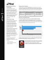
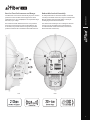
Datasheet
Full-Duplex, Point-to-Point
Gigabit Radio
Models: AF-24, AF-24HD, AF-5, AF-5U
High Performance Wireless Backhaul
Extreme, Long-Range Links
Worldwide License-Free Operation
Datasheet
Revolutionary Wireless
Technology
Introducing airFiber®, a truly
revolutionary Point-to-Point wireless
platform from Ubiquiti Networks.
Housed in a compact, highly efficient
form factor, airFiber delivers amazing
wireless gigabit+ performance, low
latency, and long range. airFiber
ushers in a new era in price-disruptive
wireless technology ideal for carrier
backhaul, building-to-building
enterprise use, or public safety
applications.
Efficient by Design
Every detail of airFiber was designed
and engineered by the Ubiquiti
R&D Team. From the silicon chip
up to the innovative split-antenna
architecture, the Ubiquiti R&D Team
created airFiber to deliver superior
throughput with efficiency. airFiber
was purpose‑built to create a high
performance backhaul.
Designed for Freedom
airFiber operates in worldwide, license-free, 24 or 5 GHz frequencies. Anyone
around the world can purchase and operate airFiber without any special permits,
paperwork, or added licensing costs. Users are free to locate, deploy, and operate
airFiber practically anywhere they choose (subject to local country regulations).
Description
Operating Frequency*
AF-5
Model
Mid-band 5 GHz frequencies
5470 - 5950 MHz
AF-5U
High-band 5 GHz frequencies
5725 - 6200 MHz
AF-24/AF‑24HD
24 GHz frequencies
24.05 - 24.25 GHz
* Refer to the Specifications section for more information.
FiOS
Built for Speed and Range
Cable
airFiber delivers gigabit performance at 1.2+ Gbps for airFiber AF-5/AF-5U,
DSL for airFiber AF-24, and 2 Gbps for airFiber AF-24HD. To put this in
1.4+ Gbps
perspective, airFiber can transmit a 100 MB file in less than a second. Rivaling
0
100
200
300
400
500
600
700
800
900
1000 1100 1200 1300 1400 1500 1600 1700 1800 1900 2000
common broadband
providers,
airFiber
download
speed is up to 100x faster. With
Speed
Comparison (Mbps)
speed and throughput surpassing
conventional
wired backhauls, airFiber prevails
over expensive and labor-intensive wired infrastructures.
Plug and Play Deployment
Based on Ubiquiti’s innovative
and intuitive airOS®, the airFiber
Configuration Interface enables
quick deployment. With installation
efficiency in mind, the mechanical
design allows easy installation by one
person. A two‑person installation crew
can effectively install and align an
airFiber link.
To fine-tune the alignment, the
received signal levels can be
conveniently accessed via any of these
methods:
• airFiber LED display
• airFiber Configuration Interface
• Audio tone feature
2
FiOS
Cable
DSL
0
100
200
300
400
500
600
700
800
900
1000
1100
1200
1300
1400
1500
1600
1700
1800
1900
2000
Speed Comparison (Mbps)
airFiber is built for long-range use: up to 13+ km for airFiber AF-24, up to 20+ km
for airFiber AF-24HD, and up to 100+ km for airFiber AF-5/AF-5U, which launches
the innovative xtreme Range Technology (xRT™) feature.
airFiber backhauls do not share the security risks associated
with wired backhauls. The long distances of wired backhauls
are vulnerable to copper theft, fiber optic damage,
vandalism, and accidental breakage. With airFiber, only the
installation points of the airFiber links need to be secured.
Innovative Proprietary Modem Technology
Ubiquiti’s innovative proprietary modem technology was purpose-built to
address the specific challenges of outdoor, PtP (Point‑to-Point) bridging and
high-performance network backhauls. Every aspect of the radio has been carefully
simulated and designed to optimize range, speed, and latency performance in the
harshest RF noise environments.
Datasheet
Synchronous Data Transmission and Reception
Conventional wireless standards impose a latency by having to receive a packet
before a packet is transmitted. airFiber can transmit data synchronously without
any wait time. airFiber features traditional TDD and FDD modes of operation
in addition to the proprietary Hybrid Division Duplexing (HDD) mode, which
provides a breakthrough in range and spectral efficiency performance.
Based on the ranging algorithm built into the air protocol, the airFiber radios
use patent-pending HDD technology to calculate the propagation delay and
know when each radio can transmit and receive, so they send packets in precise
synchronization. Packet transmission latency is virtually eliminated.
RX
RX
enc
u
Freq
yA
Freq
u
ency
B
airFiber AF-5/AF-5U
TX
TX
airFiber AF-5/AF-5U Radios in Full-Duplex Mode
Innovative Dual-Antenna Architecture
airFiber features a dual-independent, 2x2 MIMO, high-gain reflector antenna
system. Separate yet integrated transmit (TX) and receive (RX) antennas help
extend link budgets by eliminating the extra RF losses caused by the switches or
duplexers required in systems with common TX/RX antennas.
Network Management
airFiber supports a variety of features to help you manage your network:
• Network management options A choice between the greater security of
out‑of-band management and the convenience of in-band management.
• SNMP support Full SNMP support to aid in network management.
• Local and remote airFiber status information Available on the Main tab of
the airFiber Configuration Interface.
airFiber AF-24 shown without radome
3
Datasheet
There are two airFiber models available for the 5 GHz
spectrum. The mid-band model, AF-5, features the popular
mid‑band frequencies, which are freely used in many parts
of the world.
Side
4
The high-band (5.7 - 6.2 GHz) model, AF-5U, has robust
filtering to enable co-location with devices operating in
the lower 5 GHz bands while allowing operation at a higher
output power in many areas of the world.
Back
Radio Alignment Display
Ubiquiti Networks introduces our proprietary INVICTUS core communications
processing engine. The speed, power, and efficiency of this integrated circuit
enhances the performance of the airFiber AF-5/AF-5U.
™
Efficient Use of 5 GHz Band
airFiber AF-5/AF-5U features 1 MHz center channel resolution with market‑leading
Power Envelope Tracking technology. The airFiber AF-5/AF-5U accurately and
continuously controls transmit power relative to the band edge. The power level
automatically tracks to optimize performance near band edges, allowing you to
choose the part of the band with the least interference.
Newly designed for the airFiber
AF-5/AF-5U, the Radio Alignment
Display (RAD) makes aiming quicker
and easier. The dual, calibrated signal
strength indicators display the actual
signal strength on the local and
remote airFiber radios in real time. The
comprehensive array of radio status
indicators display the following:
• GPS synchronization status
Long-Range Links
• Master/slave mode
Newly developed for the airFiber AF-5/AF-5U, the patent-pending xRT feature
uses an innovative, adaptive multi-channel coding scheme to enhance radio
transceiver performance, thereby maximizing your link budget and spectrum
utilization – while still maintaining regulatory compliance. This results in links that
can span distances from 10 m up to 100+ km.
• RF link status
Quick and Easy Installation
The unique sliding-clamp design of the airFiber AF-5/AF-5U allows mounting
hardware to be pre‑assembled prior to installation – no more dropped screws at
the top of the tower. As an added convenience, the drop‑in cradle mount design
allows the installer to attach mounting hardware to the pole without having to
support the weight of the airFiber radio during installation.
Datasheet
Superior Processing
• RF overload warning
• Current modulation mode
• Link activity and speed for wired
management and data ports
GPS
OVERLOAD
MASTER
LINK
8X
REMOTE
6X
RESET
MANAGEMENT
ACT
SPEED
4X to 0.25X
LOCAL
AUX
DATA
ACT
SPEED
5
Specifications
airFiber AF-5/AF-5U
Dimensions
Datasheet
Weight
Max. Power Consumption
Power Supply
Power Method
938.4 x 468.4 x 281.4 mm (36.94 x 18.44 x 11.08")
16 kg (35.27 lb) Mount Included
40 W
50V, 1.2A PoE GigE Adapter (Included)
Passive Power over Ethernet
Supported Voltage Range
42-58VDC
Certifications
CE, FCC, IC
Mounting
Wind Loading
Wind Survivability
Operating Temperature
LEDs
Pole Mount Kit (Included)
863 N @ 200 km/hr (194 lbf @ 125 mph)
200 km/hr (125 mph)
-40 to 55° C (-40 to 131°F)
(12) Status LEDs:
Data Port Link/Activity
Data Port Speed
Management Port Link/Activity
Management Port Speed
GPS Synchronization
Master/Slave
Link Status
Modulation Mode 0.25x to 4x, 6x, 8x, 10x (Unlabeled), Overload
Remote and Local Displays (Calibrated Signal Strength)
Operating Frequency
AF-5
FCC 15.247, 15.407, IC RSS-210
ETSI EN 301 893, EN 302 502
Other Regions
AF-5U
FCC 15.247, IC RSS-210
ETSI EN 302 502
Other Regions
5470 - 5600 MHz, 5650 - 5850 MHz
5470 - 5875 MHz
5470 - 5950 MHz
5725 - 5850 MHz
5725 - 5875 MHz
5725 - 6200 MHz
Interface
Data Port
Management Port
Auxiliary Port
(1) 10/100/1000 Ethernet Port
(1) 10/100 Ethernet Port
(1) RJ-12, Alignment Tone Port
System
Maximum Throughput
Maximum Range
Packets per Second
Encryption
Uplink/Downlink Ratio
6
1.2+ Gbps
100+ km (Dependent on Regulatory Region)
1+ Million
128-Bit AES
50% Fixed
Radio Frame Synchronization
GPS
Dynamic Frequency Selection
AF-5
AF-5U
CE, FCC/IC
CE, (FCC/IC Not Applicable)
Spatial
Streams
Modulation
Sensitivity
(10 MHz)
Sensitivity
(20 MHz)
Sensitivity
(40 MHz)
Sensitivity
(50 MHz)
FDD Capacity*
TDD Capacity*
10x
1024QAM
-64 dBm
-61 dBm
-59 dBm
-58 dBm
1280 Mbps
640 Mbps
8x
256QAM
-70 dBm
-67 dBm
-65 dBm
-64 dBm
1024 Mbps
512 Mbps
6x
64QAM
-77 dBm
-74 dBm
-72 dBm
-71 dBm
768 Mbps
384 Mbps
4x
16QAM MIMO
-84 dBm
-81 dBm
-79 dBm
-78 dBm
512 Mbps
256 Mbps
2x
QPSK MIMO
-90 dBm
-87 dBm
-85 dBm
-84 dBm
256 Mbps
128 Mbps
1x
½ Rate QPSK xRT
-93 dBm
-90 dBm
-88 dBm
-87 dBm
128 Mbps
64 Mbps
¼x
¼x QPSK xRT
-95 dBm
-93 dBm
-92 dBm
-91 dBm
32 Mbps
16 Mbps
Datasheet
airFiber AF-5/AF-5U Receive Sensitivity
* FDD = (2) 50 MHz channels and TDD = (1) 50 MHz channel
airFiber AF-5/AF-5U Radio Frequency
GPS
GPS Clock Synchronization
Transceiver
EIRP
~50 dBm (Dependent on Regulatory Region and Frequency Band)
Frequency Accuracy
±2.5 ppm without GPS Synchronization
±0.2 ppm with GPS Synchronization
Channel Bandwidth
10/20/30/40/50 MHz
Modulation
1024QAM MIMO
256QAM MIMO
64QAM MIMO
16QAM MIMO
QPSK MIMO
½ Rate QPSK xRT
¼ Rate QPSK xRT
Integrated Split Antenna
TX Gain
23 dBi
RX Gain
23 dBi
Beamwidth
Front-to-Back Ratio
Polarity
Cross-Polarity Isolation
6°
70 dB
Dual-Slant Polarization
> 28 dB
7
Datasheet
Superior 24 GHz Performance
Two airFiber 24 GHz Models
airFiber AF-24/AF-24HD provides a breakthrough in 24 GHz
backhaul performance.
Two models deliver superior speed with spectral efficiency in
the worldwide, license-free, 24 GHz radio band.
Systems for millimeter‑wave frequencies typically experience
RF losses when part of the RF is lost in the switches and filters.
The standard model, AF-24, delivers up to 1.4+ Gbps
throughput at a range of up to 13+ km.
The Ubiquiti R&D team eliminated such RF losses with
separate yet integrated TX and RX antennas, so the link
budget is robust and the airFiber AF-24/AF-24HD has better
noise figure and higher transmit power efficiency.
The heavy-duty model, AF-24HD, provides more throughput
at up to 2 Gbps and increased range of up to 20+ km. It also
includes a more rugged exterior with a metal reflector, to
protect against nature’s harshest elements.
Side
8
Back
Specifications
airFiber AF-24
Operating Frequency
24.05 – 24.25 GHz
649 x 426 x 303 mm (25.55 x 16.77 x 11.93")
Weight
10.5 kg (23.15 lb) Mount Included
Max. Power Consumption
50 W
Power Supply
50V, 1.2A PoE GigE Adapter (Included)
Power Method
Passive Power over Ethernet
Supported Voltage Range
Datasheet
Dimensions
42-58VDC
Certifications
CE, FCC, IC
Wind Loading
480 N @ 200 km/hr (108 lbf @ 125 mph)
Wind Survivability
200 km/hr (125 mph)
Mounting
Pole Mount Kit (Included)
Operating Temperature
-40 to 55° C (-40 to 131° F)
LEDs
(8) Status LEDs:
Data Port Speed
Data Port Link/Activity
Configuration Port Speed
Configuration Port Link/Activity
GPS Synchronization
Modulation Mode
Master/Slave
RF Status
(1) Two-Digit LED Display Calibrated in dBm
Interface
Data Port
(1) 10/100/1000 Ethernet Port
Configuration Port
(1) 10/100 Ethernet Port
Auxiliary Port
(1) RJ-12, Alignment Tone Port
System
Maximum Throughput
1.4+ Gbps
Maximum Range
13+ km
Packets per Second
> 1 Million
Encryption
128-Bit AES
Uplink/Downlink Ratio
50% Fixed
airFiber AF-24 Receive Sensitivity
Modulation
Sensitivity
FDD Capacity*
TDD Capacity*
64QAM
-66 dBm
1500 Mbps
760 Mbps
16QAM
-72 dBm
1000 Mbps
507 Mbps
QPSK MIMO
-78 dBm
500 Mbps
253 Mbps
QPSK SISO
-80 dBm
250 Mbps
127 Mbps
¼x QPSK SISO
-87 dBm
62.5 Mbps
31.7 Mbps
* FDD = (2) 100 MHz channels and TDD = (1) 100 MHz channel
9
airFiber AF-24 Radio Frequency
GPS
GPS Clock Synchronization
Datasheet
Transceiver
EIRP
Frequency Accuracy
~33 dBm (FCC/IC), ~20 dBm (CE)
±2.5 ppm without GPS Synchronization
±0.2 ppm with GPS Synchronization
Channel Bandwidth
100 MHz
Operating Channels
24.1 GHz, 24.2 GHz
Modulation
64QAM MIMO
16QAM MIMO
QPSK MIMO
QPSK SISO
¼x QPSK SISO
Integrated Split Antenna
TX Gain
33 dBi
RX Gain
38 dBi
Beamwidth
< 3.5°
Front-to-Back Ratio
Polarity
Cross-Polarity Isolation
10
70 dB
Dual-Slant Polarization
> 28 dB
Robust Mechanical Assembly
Our INVICTUS custom silicon dramatically improves wireless
performance. The AF‑24HD model supports the dense
modulation rates, up to 256QAM, that are required for high
data rates, up to 2 Gbps.
An independent lab has tested the airFiber mechanical
assembly to meet MIL‑STD‑810G, a rigorous United States
MIL‑STD (Military Standard) that defines a variety of
challenging environmental conditions.
The airFiber AF-24/AF-24HD features the most powerful
automatic compensation for path loss degradation due
to rain fade, so it provides the best range among 24 GHz
products and allows for constellation threshold extension.
The mechanical assembly has also undergone vibration
testing using an extended version of IEC 60068‑2‑6,
an environmental standard of the IEC (International
Electrotechnical Commission).
10
Side
Datasheet
Best-in-Class Performance and Range
5 10
5 0
Back
11
Specifications
airFiber AF-24HD
Operating Frequency
24.05 – 24.25 GHz
Datasheet
Dimensions
593 x 768 x 370 mm (23.35 x 30.24 x 14.57")
Weight
17.3 kg (38.14 lb) Mount Included
Max. Power Consumption
50 W
Power Supply
50V, 1.2A PoE GigE Adapter (Included)
Power Method
Passive Power over Ethernet
Supported Voltage Range
42-58VDC
Certifications
CE, FCC, IC
Wind Loading
770 N @ 200 km/hr (170 lbf @ 125 mph)
Wind Survivability
200 km/hr (125 mph)
Mounting
Pole Mount Kit (Included)
Operating Temperature
-40 to 55° C (-40 to 131° F)
LEDs
(8) Status LEDs:
Data Port Speed
Data Port Link/Activity
Configuration Port Speed
Configuration Port Link/Activity
GPS Synchronization
Modulation Mode
Master/Slave
RF Status
(1) Two-Digit LED Display Calibrated in dBm
Interface
Data Port
(1) 10/100/1000 Ethernet Port
Configuration Port
(1) 10/100 Ethernet Port
Auxiliary Port
(1) RJ-12, Alignment Tone Port
System
Maximum Throughput
2 Gbps
Maximum Range
20+ km
Packets per Second
> 1 Million
Encryption
128-Bit AES
Uplink/Downlink Ratio
50% Fixed
airFiber AF-24HD Receive Sensitivity
Modulation
Sensitivity
FDD Capacity*
TDD Capacity*
256QAM
-60 dBm
2000 Mbps
1024 Mbps
64QAM
-66 dBm
1500 Mbps
760 Mbps
16QAM
-72 dBm
1000 Mbps
507 Mbps
QPSK MIMO
-78 dBm
500 Mbps
253 Mbps
QPSK SISO
-80 dBm
250 Mbps
127 Mbps
¼x QPSK SISO
-87 dBm
62.5 Mbps
31.7 Mbps
* FDD = (2) 100 MHz channels and TDD = (1) 100 MHz channel
12
airFiber AF-24HD Radio Frequency
GPS
GPS Clock Synchronization
EIRP
Frequency Accuracy
~33 dBm (FCC/IC), ~20 dBm (CE)
±2.5 ppm without GPS Synchronization
±0.2 ppm with GPS Synchronization
Channel Bandwidth
100 MHz
Operating Channels
24.1 GHz, 24.2 GHz
Modulation
256QAM MIMO
64QAM MIMO
16QAM MIMO
QPSK MIMO
QPSK SISO
¼x QPSK SISO
Integrated Split Antenna
TX Gain
33 dBi
RX Gain
40 dBi
Beamwidth
< 3.5°
Front-to-Back Ratio
70 dB
Polarity
Cross-Polarity Isolation
Dual-Slant Polarization
> 28 dB
All specifications in this document are subject to change without notice.
©2012-2015 Ubiquiti Networks, Inc. All rights reserved. Ubiquiti, Ubiquiti Networks, the Ubiquiti U logo, the Ubiquiti beam
logo, airFiber, airOS, INVICTUS, and xRT are trademarks or registered trademarks of Ubiquiti Networks, Inc. in the United States
and in other countries. All other trademarks are the property of their respective owners.
www.ubnt.com
JL021815
Datasheet
Transceiver