1
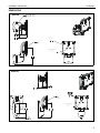
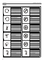
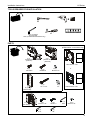
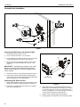
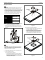
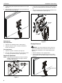
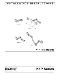
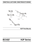
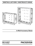
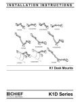
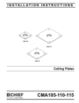
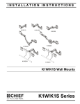
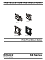
INSTALLATION INSTRUCTIONS
Instrucciones de instalación
Installationsanleitung
Instruções de Instalação
K0P100
K0W100BXI2
Istruzioni di installazione
Installatie-instructies
Instructions d´installation
K0W100
K0W100BXI2TB
Pitch/Pivot Mount Series
Spanish Product Description
German Product Description
Portuguese Product Description
Italian Product Description
Dutch Product Description
French Product Description
K0 Series
K0 Series
Installation Instructions
DISCLAIMER
Milestone AV Technologies and its affiliated corporations and
subsidiaries (collectively “Milestone”), intend to make this
manual accurate and complete. However, Milestone makes no
claim that the information contained herein covers all details,
conditions or variations, nor does it provide for every possible
contingency in connection with the installation or use of this
product. The information contained in this document is subject
to change without notice or obligation of any kind. Milestone
makes no representation of warranty, expressed or implied,
regarding the information contained herein. Milestone assumes
no responsibility for accuracy, completeness or sufficiency of
the information contained in this document.
Chief® is a registered trademark of Milestone AV Technologies.
All rights reserved.
WARNING: Exceeding the weight capacity can result in
serious personal injury or damage to equipment! It is the
installer’s responsibility to make sure the combined weight of
all components attached to the K0 Series Monitor Arm up to
(and including) the display does not exceed the weight limits
in the table below. Use with products heavier than the
maximum weight indicated may result in collapse of the
mount and its accessories causing possible injury.
MODEL
Max Weight
K0P100
40 lbs (18.14 kg)
K0W100
40 lbs (18.14 kg)
K0W100BXI2
2 lbs (0.9 kg)
K0W100BXI2TB
2 lbs (0.9 kg)
IMPORTANT SAFETY INSTRUCTIONS!
WARNING: Do not use this product outdoors.
WARNING: A WARNING alerts you to the possibility of
serious injury or death if you do not follow the instructions.
CAUTION: A CAUTION alerts you to the possibility of
damage or destruction of equipment if you do not follow the
corresponding instructions.
WARNING: Failure to read, thoroughly understand, and
follow all instructions can result in serious personal injury,
damage to equipment, or voiding of factory warranty! It is the
installer’s responsibility to make sure all components are
properly assembled and installed using the instructions
provided.
WARNING: Failure to provide adequate structural strength
for this component can result in serious personal injury or
damage to equipment! It is the installer’s responsibility to
make sure the structure to which this component is attached
can support five times the combined weight of all equipment.
Reinforce the structure as required before installing the
component. The wall to which the mount is being attached
may have a maximum drywall thickness of 5/8” (1.6cm).
WARNING: Use this mounting system only for its intended
use as described in these instructions. Do not use
attachments not recommended by the manufacturer.
WARNING: Never operate this mounting system if it is
damaged. Return the mounting system to a service center for
examination and repair.
2
--SAVE THESE INSTRUCTIONS!--
Installation Instructions
K0 Series
DIMENSIONS
K0P100
1.50" - 1.90"
[38.1 - 50.8]
2.60
66.1
TILT RANGE
UP
10 DOWN
INTERFACE
ROTATION
RANGE
90
MOUNTING PATTERN
COMPATIBILITY
100 X 100
75 X 75
5.29
134.5
K0W100
3.20
81.3
TILT RANGE
UP
10 DOWN
3.22
81.7
90
MOUNTING PATTERN
COMPATIBILITY
100 X 100
75 X 75
4.91
124.7
3
K0 Series
Installation Instructions
LEGEND
4
Tighten Fastener
Pencil Mark
Apretar elemento de fijación
Marcar con lápiz
Befestigungsteil festziehen
Stiftmarkierung
Apertar fixador
Marcar com lápis
Serrare il fissaggio
Segno a matita
Bevestiging vastdraaien
Potloodmerkteken
Serrez les fixations
Marquage au crayon
Loosen Fastener
Drill Hole
Aflojar elemento de fijación
Perforar
Befestigungsteil lösen
Bohrloch
Desapertar fixador
Fazer furo
Allentare il fissaggio
Praticare un foro
Bevestiging losdraaien
Gat boren
Desserrez les fixations
Percez un trou
Phillips Screwdriver
Adjust
Destornillador Phillips
Ajustar
Kreuzschlitzschraubendreher
Einstellen
Chave de fendas Phillips
Ajustar
Cacciavite a stella
Regolare
Kruiskopschroevendraaier
Afstellen
Tournevis à pointe cruciforme
Ajuster
Open-Ended Wrench
Remove
Llave de boca
Quitar
Gabelschlüssel
Entfernen
Chave de bocas
Remover
Chiave a punte aperte
Rimuovere
Steeksleutel
Verwijderen
Clé à fourche
Retirez
By Hand
Optional
A mano
Opcional
Von Hand
Optional
Com a mão
Opcional
A mano
Opzionale
Met de hand
Optie
À la main
En option
Hex-Head Wrench
Security Wrench
Llave de cabeza hexagonal
Llave de seguridad
Sechskantschlüssel
Sicherheitsschlüssel
Chave de cabeça sextavada
Chave de segurança
Chiave esagonale
Chiave di sicurezza
Zeskantsleutel
Veiligheidssleutel
Clé à tête hexagonale
Clé de sécurité
Installation Instructions
K0 Series
TOOLS REQUIRED FOR INSTALLATION
3/16” (included)
1/8” (included)
5/32” (included with K0P Series only)
#2
PARTS
P (1)
[iPad® interface - iPad versions only!
A (1)
[monitor arm]
(K0P100)
+
or
A (1)
[monitor arm]
(K0W100)
I2B Interface + I/M
B (4)
M4x14mm
C (4)
M4x25mm
or
D (4)
M10x5.3x10
included with K0W Series (wall mount) only!
+
F (2)
1/4 x 2 1/2”
G (2)
1/4”
E (1)
[wall bracket]
I2TB Interface + I/M
included with K0P Series (pole mount) only!
H (1)
[pole clamp]
J (4)
1/4-20 x 1 1/2”
N (1)
3/16”
K (4)
1/4-20 x 1"
L (1)
5/32”
M (1)
#10-24 x 1/4”
P (1)
1/8”
5
K0 Series
Installation Instructions
Assembly And Installation
3
set screw
6
side view
5
4
(F) x 2
(E)
(G) x 2
Figure 1
Connecting K0W Series (wall mount) to Wall
1.
Determine mounting location on wall.
2.
Use a stud finder to locate 2" x 4" wood stud.
3.
Use wall bracket (E) to mark and drill two 1/8 x 2 1/2” holes
in wall at desired mounting location. (See Figure 1)
4.
Use two 1/4-2 1/2” hex head lag screws (F) and two 1/4”
washers (G) to install wall bracket (E) onto wall. (See
Figure 1)
(H)
IMPORTANT ! : Over tightening screws (F) may cause
bracket to compress into soft wall surface resulting in
difficult mount installation or improper engaging of set
screw in Step 6.
5.
Hang monitor arm (A) over wall bracket (E). (See Figure 1)
6.
Secure monitor arm to wall bracket (E) by tightening set
screw. Ensure set screw engages back side of wall bracket
(E) to properly secure mount. (See Figure 1)
3
(J or K) x 4
K0P assembly
Connecting K0P Series to Pole
1.
Determine approximate location for mount keeping in mind
display size, extension, height adjustment requirements.
2.
Place mount (A) against pole with clamp (H) on opposite
side of pole. (See Figure 2)
6
Figure 2
3.
Using 5/32” hex key (L) and appropriate length screws,
loosely attach K0P assembly to pole clamp (H). If installing
to 1 1/2” NPT pipe, use 1/4-20 x 1 1/2” button head cap
screws (J). If installing to 1 1/2” diameter pipe, use 1/4-20 x
1" button head cap screws (K). (See Figure 2)
4.
Position mount at desired height and orientation.
5.
Equally tighten screws against mount and the pole clamp.
Installation Instructions
K0 Series
Display Installation
(for flush mounting holes)
WARNING: Exceeding the weight capacity can result in
serious personal injury or damage to equipment! It is the
installer’s responsibility to make sure the combined weight of
all components attached to the K0 Series Monitor Arm up to
(and including) the display does not exceed the weight limits
in the table below. Use with products heavier than the
maximum weight indicated may result in collapse of the
mount and its accessories causing possible injury.
MODEL
Max Weight
K0P100
40 lbs (18.14 kg)
K0W100
40 lbs (18.14 kg)
K0W100BXI2
2 lbs (0.9 kg)
K0W100BXI2TB
2 lbs (0.9 kg)
quick release
faceplate
(B) x 4
3
NOTE: For K0W100BXI2 mounts, refer to FSBI2B installation
instructions to install iPad® to mounting arm.
1.
Remove quick release faceplate from mount by pulling
quick release lever and sliding faceplate off mount. (See
Figure 3)
Figure 4
For recessed mounting hole installation:
•
•
1
Place four spacers (D) on top of mounting holes
on back of display. (See Figure 5)
Using Phillips screwdriver, carefully install four
M4x25mm screws (C) through corresponding
holes on faceplate, spacers (D) and into the
mounting holes on the display. (See Figure 5)
(for recessed mounting holes)
quick release
faceplate
3
1
quick release lever
(C) x 4
(D) x 4
Figure 3
WARNING: Only remove display from mount when the
display can be lifted up from the mount! DO NOT remove
display unless the display is in the upright position! See
Display Removal section for details.
2.
Carefully place display face down on protective surface.
3.
Connect faceplate to display
For flush mounting hole installation:
•
Using Phillips screwdriver, carefully install four
M4x14mm screws (B) through corresponding
holes on faceplate and into the mounting holes on
the display. (See Figure 4)
Figure 5
7
K0 Series
Installation Instructions
4.
Position display with faceplate attached above mount. (See
Figure 6)
5.
Slide faceplate onto mounting head until quick release tab
clicks into place. (See Figure 6)
5.
The monitor may be adjusted 90 degrees in either direction
in order to provide a portrait view of the monitor. (See Figure
8)
6.
Use 3/16” hex key (N) to adjust rotational adjustment screw
to adjust rotational tension. (See Figure 8)
rotational tension
5
pivot point
tension
3
1
5
pitch
tension
Figure 6
Adjustments
Figure 8
Pitch Adjustment
1.
Adjust pitch to desired tilt position. (See Figure 8)
2.
Adjust pitch tension screw to change the adjustment
tension. (See Figure 8)
Display Removal
WARNING: Only remove display from mount when the
display can be lifted up from the mount! DO NOT remove
display unless the display is in the upright position! (See
Figure 9)
Pivot Adjustment
3.
Adjust pivot position as desired. (See Figure 8)
4.
Use 3/16” hex key (N) to adjust pivot point tension screws
to change pivot adjustment tension. (See Figure 8)
Rotational Adjustment
NOTE: (Optional) Rotational adjustment may be locked by
1.
Make sure display is in the upright position.
2.
Remove quick release faceplate from mount by pulling
quick release lever and sliding faceplate off mount. (See
Figure 9)
installing rotational locking screw (M) into back of
faceplate. (See Figure 7)
(M)
2
Figure 7
8
Figure 9
quick release tab
Installation Instructions
K0 Series
9
K0 Series
10
Installation Instructions
Installation Instructions
K0 Series
11
K0 Series
Installation Instructions
USA/International
Europe
Chief, a products division of
Milestone AV Technologies
8800-002476 Rev02
2014 Milestone AV Technologies
www.chiefmfg.com
07/14
Asia Pacific
A
P
F
A
P
F
A
6436 City West Parkway, Eden Prairie, MN 55344
800.582.6480 / 952.225.6000
877.894.6918 / 952.894.6918
Franklinstraat 14, 6003 DK Weert, Netherlands
+31 (0) 495 580 852
+31 (0) 495 580 845
Office No. 918 on 9/F, Shatin Galleria
18-24 Shan Mei Street
Fotan, Shatin, Hong Kong
P 852 2145 4099
F 852 2145 4477