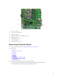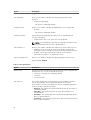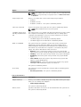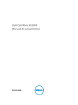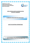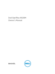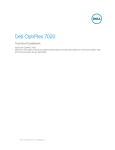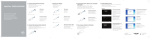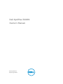
1
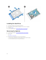
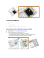
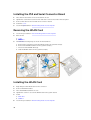
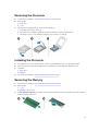
Dell OptiPlex 3020M
Owner's Manual
Regulatory Model: D08U
Regulatory Type: D08U001
Notes, Cautions, and Warnings
NOTE: A NOTE indicates important information that helps you make better use of your computer.
CAUTION: A CAUTION indicates either potential damage to hardware or loss of data and tells you
how to avoid the problem.
WARNING: A WARNING indicates a potential for property damage, personal injury, or death.
Copyright © 2014 Dell Inc. All rights reserved. This product is protected by U.S. and international copyright and
intellectual property laws. Dell™ and the Dell logo are trademarks of Dell Inc. in the United States and/or other
jurisdictions. All other marks and names mentioned herein may be trademarks of their respective companies.
2014 - 08
Rev. A00
Contents
1 Working on Your Computer................................................................................5
Before Working Inside Your Computer................................................................................................ 5
Turning Off Your Computer..................................................................................................................6
After Working Inside Your Computer................................................................................................... 7
2 Installing the Accessories....................................................................................8
Installing the Power Adapter.................................................................................................................8
Installing the Dell OptiPlex Micro Dual VESA Mount........................................................................... 9
Installing the Dell OptiPlex Micro VESA Mount...................................................................................11
Installing the Dell OptiPlex Micro Vertical Stand................................................................................12
Installing the Dell OptiPlex Micro Console with DVD-RW................................................................ 13
Installing the Dell OptiPlex Micro All-in-One Mount Behind the Monitor........................................ 17
3 Removing and Installing Components........................................................... 23
Front and Back View........................................................................................................................... 23
Removing the Cover........................................................................................................................... 23
Installing the Cover............................................................................................................................. 24
Removing the Processor Fan Module................................................................................................ 25
Installing the Processor Fan Module.................................................................................................. 26
Removing the Speaker........................................................................................................................ 26
Installing the Speaker.......................................................................................................................... 26
Removing the Hard Drive....................................................................................................................27
Installing the Hard Drive..................................................................................................................... 28
Removing the Heatsink ......................................................................................................................28
Installing the Heatsink.........................................................................................................................29
Removing the PS2 and Serial Connector Board................................................................................ 29
Installing the PS2 and Serial Connector Board..................................................................................30
Removing the WLAN Card..................................................................................................................30
Installing the WLAN Card....................................................................................................................30
Removing the Processor..................................................................................................................... 31
Installing the Processor....................................................................................................................... 31
Removing the Memory........................................................................................................................31
Installing the Memory......................................................................................................................... 32
Removing the Coin-Cell Battery........................................................................................................ 32
Installing the Coin-Cell Battery.......................................................................................................... 32
System Board Layout.......................................................................................................................... 32
Removing the System Board.............................................................................................................. 33
Installing the System Board................................................................................................................ 34
4 System Setup....................................................................................................... 36
Boot Sequence....................................................................................................................................36
Navigation Keys................................................................................................................................... 36
System Setup Options......................................................................................................................... 37
Updating the BIOS ............................................................................................................................. 46
Jumper Settings.................................................................................................................................. 46
System and Setup Password...............................................................................................................46
Assigning a System Password and Setup Password.....................................................................47
Deleting or Changing an Existing System and/or Setup Password.............................................47
Disabling a System Password....................................................................................................... 48
5 Specifications...................................................................................................... 49
6 Contacting Dell................................................................................................... 53
Working on Your Computer
1
Before Working Inside Your Computer
Use the following safety guidelines to help protect your computer from potential damage and to help to
ensure your personal safety. Unless otherwise noted, each procedure included in this document assumes
that the following conditions exist:
•
You have read the safety information that shipped with your computer.
•
A component can be replaced or--if purchased separately--installed by performing the removal
procedure in reverse order.
WARNING: Disconnect all power sources before opening the computer cover or panels. After you
finish working inside the computer, replace all covers, panels, and screws before connecting to
the power source.
WARNING: Before working inside your computer, read the safety information that shipped with
your computer. For additional safety best practices information, see the Regulatory Compliance
Homepage at www.dell.com/regulatory_compliance
CAUTION: Many repairs may only be done by a certified service technician. You should only
perform troubleshooting and simple repairs as authorized in your product documentation, or as
directed by the online or telephone service and support team. Damage due to servicing that is
not authorized by Dell is not covered by your warranty. Read and follow the safety instructions
that came with the product.
CAUTION: To avoid electrostatic discharge, ground yourself by using a wrist grounding strap or
by periodically touching an unpainted metal surface, such as a connector on the back of the
computer.
CAUTION: Handle components and cards with care. Do not touch the components or contacts
on a card. Hold a card by its edges or by its metal mounting bracket. Hold a component such as a
processor by its edges, not by its pins.
CAUTION: When you disconnect a cable, pull on its connector or on its pull-tab, not on the cable
itself. Some cables have connectors with locking tabs; if you are disconnecting this type of cable,
press in on the locking tabs before you disconnect the cable. As you pull connectors apart, keep
them evenly aligned to avoid bending any connector pins. Also, before you connect a cable,
ensure that both connectors are correctly oriented and aligned.
NOTE: The color of your computer and certain components may appear differently than shown in
this document.
To avoid damaging your computer, perform the following steps before you begin working inside the
computer.
1.
Ensure that your work surface is flat and clean to prevent the computer cover from being scratched.
2.
Turn off your computer (see Turning Off Your Computer).
5
CAUTION: To disconnect a network cable, first unplug the cable from your computer and
then unplug the cable from the network device.
3.
Disconnect all network cables from the computer.
4.
Disconnect your computer and all attached devices from their electrical outlets.
5.
Press and hold the power button while the computer is unplugged to ground the system board.
6.
Remove the cover.
CAUTION: Before touching anything inside your computer, ground yourself by touching an
unpainted metal surface, such as the metal at the back of the computer. While you work,
periodically touch an unpainted metal surface to dissipate static electricity, which could
harm internal components.
Turning Off Your Computer
CAUTION: To avoid losing data, save and close all open files and exit all open programs before
you turn off your computer.
1.
Shut down the operating system:
•
In Windows 8:
– Using a touch-enabled device:
a.
Swipe in from the right edge of the screen, opening the Charms menu and select
Settings.
b.
Select the
and then select Shut down
– Using a mouse:
•
a.
Point to upper-right corner of the screen and click Settings.
b.
Click the
and select Shut down.
In Windows 7:
1.
Click Start
2.
Click Shut Down.
.
or
2.
6
.
1.
Click Start
2.
Click the arrow in the lower-right corner of the Start menu as shown below, and then click
Shut Down..
Ensure that the computer and all attached devices are turned off. If your computer and attached
devices did not automatically turn off when you shut down your operating system, press and hold
the power button for about 6 seconds to turn them off.
After Working Inside Your Computer
After you complete any replacement procedure, ensure you connect any external devices, cards, and
cables before turning on your computer.
1.
Replace the cover.
CAUTION: To connect a network cable, first plug the cable into the network device and then
plug it into the computer.
2.
Connect any telephone or network cables to your computer.
3.
Connect your computer and all attached devices to their electrical outlets.
4.
Turn on your computer.
5.
If required, verify that the computer works correctly by running the Dell Diagnostics.
7
Installing the Accessories
This section provides detailed information on how to install the following accessories:
•
Power Adapter
•
Dell OptiPlex Micro Dual VESA Mount
•
Dell OptiPlex Micro VESA Mount
•
Dell OptiPlex Micro Vertical Stand
•
Dell OptiPlex Micro Console with DVD-RW
•
Dell OptiPlex Micro All-in-One Mount
Installing the Power Adapter
1.
Perform the following steps as shown in the illustration:
a. Slide to open the cover of the power adapter [1].
b. Install the power cable to the power adapter and place the power adapter in the box [ 2,3].
2.
8
Insert the cable into the box and slide back the cover to lock it.
2
Installing the Dell OptiPlex Micro Dual VESA Mount
Recommended Screws:
Screw Type
Used in
M4 x L10 mm, Pan head screw
Monitor
Prerequisite: Install the power adapter.
1.
Align the dual VESA mount behind the monitor and tighten the screws to secure the dual VESA
mount to the monitor.
2.
Perform the following steps as shown in the illustration:
a. Slide the computer into the dual VESA mount. [1]
b. Rotate the screw in clockwise direction to secure the computer to the dual VESA mount. [2]
9
3.
Slide the power adapter case through the grooves at the bottom of the dual dual VESA mount to lock
it.
4.
Connect all the cables and antenna to the computer.
10
5.
Tighten the screws to secure the arm stand to the dual VESA mount.
Installing the Dell OptiPlex Micro VESA Mount
Recommended Screws:
Screw Type
Used in
M4 x L10 mm, Pan head screw
Monitor
11
ST4 x L13 mm, Wooden screw
Wooden table
Prerequisite: Install the power adapter.
1.
Perform the following steps as shown in the illustration:
a. Tighten the screws to secure the VESA mount to the table.
b. Slide the computer into the VESA mount [1].
c. Tighten the screw to secure the computer to the VESA mount [2].
2.
Perform the following steps as shown in the illustration:
a. Slide the power adapter case through the grooves at the bottom of the VESA mount to lock it.
b. Connect all the cables and install antenna to the computer.
Installing the Dell OptiPlex Micro Vertical Stand
Align the computer on the vertical stand and ensure the tab on the vertical stand fits into the groove
or notch on the system.
12
Installing the Dell OptiPlex Micro Console with DVD-RW
Recommended Screws:
1.
Screw Type
Used in
ST4 x 13 mm, Wooden screw
Wooden table
Perform the following steps as shown in the illustration:
a. Loosen the screws that secure the cover to the optical drive console [1].
b. Slide and lift the cover upwards to remove it from the console [2].
13
2.
Perform the following steps as shown in the illustration:
a. Slide the computer into the slot [1].
b. Tighten the screw to secure the computer to the optical drive console [2].
3.
Perform the following steps as shown in the illustration:
a. Cut the strap of the power adapter cable [1].
b. Slide and insert the power adapter into the slot [2].
c. Route the cable through the notch to secure it [3].
4.
Perform the following steps as shown in the illustration:
a. Open the cable management clip [1].
b. Lift the antenna cable out [2].
c. Connect the antenna cable to the antenna connector [3].
14
5.
Route the USB cables through the cable management clip and connect them to the computer. Close
the cable management clip.
6.
Perform the following steps as shown in the illustration:
a. Prepare the wooden table by installing screws for mounting the optical drive console.
b. Align the slots on the optical drive console with the screws on the table and slide the optical drive
console and lock it.
c. Tighten the screws to secure the optical drive console to the wooden table.
15
7.
Install the antenna to the optical drive console.
8.
Perform the following steps as shown in the illustration:
a. Slide and insert the cover to its position [1].
b. Tighten the screws to secure the cover to the chassis [2].
16
Installing the Dell OptiPlex Micro All-in-One Mount
Behind the Monitor
Recommended Screws:
Screw Type
Used with
M4 X L8 mm, pitch 0.7 mm, selftapping screw
PUZ plate without thread screw
holes— Dell P,U,PU,UZ- series
monitors
M4 X L8 mm, pitch 0.5 mm,
machine screw
PUZ plate with thread screw
holes — Dell P,U,PU,UZ- series
monitors
17
M3 X L8 mm, pitch 0.5 mm, selftapping screw
E Plate without thread screw
holes— Dell E-series monitors
M3 X L8 mm, pitch 0.35 mm,
machine screw
E Plate with thread screw holes—
Dell E-series monitors
U Plate — Universal monitors
1.
Perform the following steps as shown in the illustration:
a. Remove the screws that secure the cover to the chassis [1].
b. Slide and lift the cover upwards to remove it from the chassis [2].
18
2.
Perform the following steps as shown in the illustration:
a. Slide the computer into the slot [1].
b. Rotate the screw in clockwise direction to secure the computer to the chassis [2].
3.
Perform the following steps as shown in the illustration:
a. Lift up the antenna cable [1].
b. Connect the antenna cable to the antenna connector on the computer [2].
19
4.
Perform the following steps as shown in the illustration:
a. Cut the strap of power adapter cable [1].
b. Slide the power adapter into the slot [2].
c. Route the cable through the clip [3].
5.
Perform the following steps as shown in the illustration:
a. Route the cable through the clip [1].
b. Connect the cable to the adapter [2].
20
6.
Align the PUZ plate to the bottom of monitor and tighten the screws.
7.
Perform the following steps as shown in the illustration:
a. Slide and lock the chassis to the PUZ plate [1].
b. Rotate the screw in clockwise direction to secure the computer [2].
c. Flip the computer along with the monitor [3].
21
8.
Perform the following steps as shown in the illustration:
a. Connect all the cables to the computer.
b. Slide the cover to its original position [1].
c. Tighten the screws to secure the cover to the chassis [2].
22
Removing and Installing Components
3
This section provides detailed information on how to remove or install the components from your
computer.
Front and Back View
Figure 1. Front and Back View
1.
power button or power light
2.
hard-drive activity light
3.
headset connector
4.
microphone connector
5.
Wi-Fi antenna connector (optional)
6.
serial and PS2 connector (optional)
7.
USB 2.0 connector (hibernate wake-up)
8.
security-cable slot
9.
USB 2.0 connectors
10.
padlock ring
11.
USB 3.0 connectors
12.
cable holder
13.
service tag
14.
network connector (Integrated Connector
Module)
15.
VGA connector
16.
DisplayPort connector
17.
power cable connector
Removing the Cover
1.
Follow the procedures in Before Working Inside Your Computer.
2.
Rotate the power cable clip to the position as shown in the illustration.
23
3.
Perform the following steps as shown in the illustration:
a. Remove the screw that secures the cover to the computer [1].
b. Slide the cover outwards [2].
c. Lift the cover up to remove it from the computer [3].
Installing the Cover
1.
Align the cover to its original position on the computer.
2.
Tighten the screw to secure the cover to the computer.
3.
Follow the procedures in After Working Inside Your Computer.
24
Removing the Processor Fan Module
1.
Follow the procedures in Before Working Inside Your Computer.
2.
Remove the cover.
3.
Perform the following steps as shown in the illustration:
a. Press the securing tabs on the sides [1].
b. Slide the processor fan module outwards [2].
c. Lift the processor fan module away from the computer [3].
4.
Disconnect the speaker and fan cables from the system board.
25
Installing the Processor Fan Module
1.
Connect the speaker and fan cable to the connectors on the system board.
2.
Place the processor fan module on the slot and slide it until it is secured.
3.
Install the cover.
4.
Follow the procedures in After Working Inside Your Computer.
Removing the Speaker
1.
2.
Follow the procedures in Before Working Inside Your Computer.
Remove the:
a. cover
b. processor fan module
3.
Perform the following steps as shown in the illustration:
a. Unthread the speaker cables from the cable clips [1].
b. Remove the screws that secure the speakers to the processor fan module [2].
c. Lift the speakers away from the processor fan module [3].
NOTE: The speaker is a part of the processor fan module.
Installing the Speaker
1.
Place and align the speakers on the processor fan module.
2.
Tighten the screws to secure the speaker to the processor fan module.
3.
Thread the cables through the cable clips to secure it.
4.
Install:
a. processor fan module
b. cover
26
5.
Follow the procedures in After Working Inside Your Computer.
Removing the Hard Drive
1.
Follow the procedures in Before Working Inside Your Computer.
2.
Remove the cover.
3.
Perform the following steps as shown in the illustration:
a. Press the securing tabs to release the hard-drive assembly [1].
b. Slide the hard-drive assembly to release it from the slot [2].
c. Lift the hard-drive assembly away from the computer [3].
4.
Perform the following steps as shown in the illustration:
a. Pry the hard-drive bracket apart to release the hard drive [1].
b. Lift the hard drive away from hard-drive bracket [2].
27
Installing the Hard Drive
1.
Insert the hard drive into the hard-drive bracket.
2.
Align and place the hard-drive assembly to its slot on the computer.
3.
Install the cover.
4.
Follow the procedures in After Working Inside Your Computer.
Removing the Heatsink
1.
Follow the procedures in Before Working Inside Your Computer.
2.
Remove the:
a. cover
b. processor fan module
3.
Perform the following steps as shown in the illustration:
a. Remove the screws that secure the heatsink to the system board [1].
b. Lift the heatsink away from the system board [2].
28
Installing the Heatsink
1.
Place the heat sink on the system board.
2.
Tighten the screws to secure the heatsink.
3.
Install:
a. processor fan module
b. cover
4.
Follow the procedures in After Working Inside Your Computer.
Removing the PS2 and Serial Connector Board
1.
Follow the procedures in Before Working Inside Your Computer.
2.
Remove the cover.
3.
Perform the following steps as shown in the illustration:
a. Disconnect the cable from the PS2 and serial connector board [1].
b. Remove the screws that secure the PS2 and serial connector board to the base panel [2].
c. Slide and lift the PS2 and serial connector board away from the computer [3].
29
Installing the PS2 and Serial Connector Board
1.
Place the PS2 and serial connector board into its slot.
2.
Tighten the screws that secure the PS2 and serial connector board to the base panel.
3.
Connect the cable to the PS2 and serial connector board.
4.
Install the cover.
5.
Follow the procedures in After Working Inside Your Computer.
Removing the WLAN Card
1.
Follow the procedures in Before Working Inside Your Computer.
2.
Remove the:
a. cover
b. hard drive
3.
Perform the following steps as shown in the illustration:
a.
b.
c.
d.
Remove the screw that secures the WLAN card to the system board [1].
Remove the WLAN bracket from the system board [2].
Disconnect the WLAN cables [3].
Slide the WLAN card from the system board [4].
Installing the WLAN Card
1.
Align and place the WLAN card on the connector.
2.
Connect the WLAN cables.
3.
Place the WLAN bracket into its slot.
4.
Tighten the screws to secure the WLAN card to the system board.
5.
Install:
a. hard drive
b. cover
6.
30
Follow the procedures in After Working Inside Your Computer.
Removing the Processor
1.
Follow the procedures in Before Working Inside Your Computer.
2.
Remove the:
a. hard drive
b. cover
3.
Perform the following steps as shown in the illustration:
a. Press the release lever down [1].
b. Move the lever outward to release it from the retention hook that secures it [2].
c. Lift the processor cover and remove the processor from its socket [3].
Installing the Processor
1.
Insert the processor into the processor socket. Ensure that the processor is properly seated.
2.
Press the release lever down and then move it inward to secure it with the retention hook.
3.
Install the:
a. hard drive
b. cover
4.
Follow the procedures in After Working Inside Your Computer.
Removing the Memory
1.
Follow the procedures in Before Working Inside Your Computer.
2.
Remove the:
a. cover
b. processor fan module
3.
Pry the retention clips away from the memory module until it pops-up. Lift and remove the memory
module from its connector.
31
Installing the Memory
NOTE: Please use DIMM 2 slot if there is only one memory module available.
1.
Align the notch on the memory-card with the tab in the system-board connector.
2.
Press down on the memory module until the retention clips spring back to secure them in place.
3.
Install the:
a. processor fan module
b. cover
4.
Follow the procedures in After Working Inside Your Computer.
Removing the Coin-Cell Battery
1.
Follow the procedures in Before Working Inside Your Computer.
2.
Remove the:
a. cover
b. hard drive
c. PS2 and serial connector board
3.
Press the release latch away from the battery. The battery pops out from the socket; lift the coin-cell
battery out of the computer.
Installing the Coin-Cell Battery
1.
Place the coin-cell battery into its slot on the system board.
2.
Press the coin-cell battery downward until the release latch springs back into place and secures it.
3.
Install the:
a. PS2 and serial connector board
b. hard drive
c. cover
4.
Follow the procedures in After Working Inside Your Computer.
System Board Layout
The following image displays the system board layout of the computer.
32
1.
processor socket
2.
processor fan connector
3.
speaker connector
4.
memory connectors ( SODIMM sockets)
5.
WLAN connector
6.
SATA HDD connector
7.
coin-cell battery
8.
PS2 and serial connector
Removing the System Board
1.
2.
Follow the procedures in Before Working Inside Your Computer.
Remove the:
a.
b.
c.
d.
e.
f.
g.
h.
i.
3.
cover
processor fan module
hard drive
heatsink
memory
processor
PS2 or serial connector board
WLAN card
coin-cell battery
Perform the following steps as shown in the illustration.
a. Remove the screws that secure the hard-drive holder to the system board [1].
b. Lift the hard drive holder away from the system board [2].
33
4.
Perform the following steps as shown in the illustration.
a. Remove the screws that secure the system board to the computer [1].
b. Slide the system board to release it from the computer [2,3].
c. Lift the system board away from the computer [4].
Installing the System Board
1.
Place the system board on the computer.
2.
Tighten the screws to secure the system board to the base panel.
3.
Place the hard drive holder on the system board.
4.
Tighten the screws that secure the hard-drive holder to the system board.
5.
Install:
34
a.
b.
c.
d.
e.
f.
g.
h.
i.
6.
coin-cell battery
WLAN card
PS2 or serial connector board
processor
memory
heatsink
hard drive
processor fan module
cover
Follow the procedures in After Working Inside Your Computer.
35
System Setup
4
System Setup enables you to manage your computer hardware and specify BIOS‐level options. From the
System Setup, you can:
•
Change the NVRAM settings after you add or remove hardware
•
View the system hardware configuration
•
Enable or disable integrated devices
•
Set performance and power management thresholds
•
Manage your computer security
Boot Sequence
Boot Sequence allows you to bypass the System Setup‐defined boot device order and boot directly to a
specific device (for example: optical drive or hard drive). During the Power-on Self Test (POST), when the
Dell logo appears, you can:
•
Access System Setup by pressing <F2> key
•
Bring up the one-time boot menu by pressing <F12> key
The one-time boot menu displays the devices that you can boot from including the diagnostic option.
The boot-menu options are:
•
Removable Drive (if available)
•
STXXXX Drive
NOTE: XXX denotes the SATA drive number.
•
Optical Drive
•
Diagnostics
NOTE: Choosing Diagnostics, will display the ePSA diagnostics screen.
The boot sequence screen also displays the option to access the System Setup screen.
Navigation Keys
The following table displays the system setup navigation keys.
NOTE: For most of the system setup options, changes that you make are recorded but do not take
effect until you re-start the system.
36
Table 1. Navigation Keys
Keys
Navigation
Up arrow
Moves to the previous field.
Down arrow
Moves to the next field.
<Enter>
Allows you to select a value in the selected field (if applicable) or follow the link in
the field.
Spacebar
Expands or collapses a drop‐down list, if applicable.
<Tab>
Moves to the next focus area.
NOTE: For the standard graphics browser only.
<Esc>
Moves to the previous page till you view the main screen. Pressing <Esc> in the main
screen displays a message that prompts you to save any unsaved changes and
restarts the system.
<F1>
Displays the System Setup help file.
System Setup Options
NOTE: Depending on the computer and its installed devices, the items listed in this section may or
may not appear
Table 2. General
Option
System Information
Description
Displays the following information:
•
•
•
•
Boot Sequence
Advanced Boot Options
System Information - Displays BIOS Version, Service Tag, Asset Tag,
Ownership Tag, Ownership Date, Manufacture Date, Express Service
Code, and Signed Firmware Update is enabled.
Memory Information - Displays Memory Installed, Memory Available,
Memory Speed, Memory Channels Mode, Memory Technology, DIMM 1
Size, and DIMM 2 Size.
Processor Information - Displays Processor Type, Core Count,
Processor ID, Current Clock Speed, Minimum Clock Speed, Maximum
Clock Speed, Processor L2 Cache, Processor L3 Cache, HT Capable,
and 64-Bit Technology.
Device Information - Displays M-SATA, SATA-0, LOM MAC Address,
Audio Controller, Video Controller, Wi-Fi Device, and Bluetooth Device.
Allows you to specify the order in which the computer attempts to find an
operating system. The options are:
•
•
•
•
•
Diskette drive
Internal HDD
USB Storage Device
CD/DVD/CD-RW Drive
Onboard NIC
•
•
Legacy
UEFI
37
Option
Description
Advance Boot Options
Enable Legacy Option ROMs - This option is required for legacy boot
mode. This option is not allowed if Secure Boot is enabled.
Date/Time
Allows you to set the date and time. The changes to the system date and
time takes effect immediately.
Table 3. System Configuration
Option
Description
Integrated NIC
Allows you to enable or disable the integrated network card. You can set
the integrated NIC to:
•
•
•
•
•
Enable UEFI Network Stack (disable by default)
Disabled
Enabled
Enabled w/PXE- This option is enabled by default.
Enabled w/Cloud Desktop
NOTE: Depending on the computer and the devices installed, the
items listed in this section may or may not appear.
Serial Port
Identifies and defines the serial port settings. This option appear only if
your system installed serial port card. You can set the serial port to:
•
•
•
•
•
Disabled
COM1 (Default)
COM2
COM3
COM4
NOTE: The operating system may allocate resources even if the
setting is disabled.
SATA Operation
Allows you to configure the operating mode of the integrated hard drive
controller.
•
•
•
Drives
Allows you to enable or disable the on-board drive:
•
SMART Reporting
38
SATA-0
This field controls if the hard drive errors for the integrated drives are
reported during system startup. This technology is part of the SMART (Self
Monitoring Analysis and Reporting Technology) specification.
•
USB Configuration
Disabled - The SATA controllers are hidden.
ATA - SATA is configured for ATA mode.
AHCI - SATA is configured for AHCI mode. This option is enabled by
default.
Enable SMART Reporting - This option is disabled by default.
This field configures the integrated USB controller. If Boot Support is
enabled, the system is allowed to boot any type of USB mass storage
devices (HDD, memory key, floppy).
Option
Description
If USB port is enabled, device attached to this port is enabled and available
for operation system.
If USB port is disabled, the operation system cannot see any device
attached to this port.
USB configuration:
•
•
•
Enable Boot Support
Rear USB Ports
a.
Port 1 (Top)
b.
Port 2 (Upper Middle)
c.
Port 3 (Lower Middle)
d. Port 4 (Bottom)*
Front USB 3.0 Ports
a.
Port 1 (Top)
b.
Port 2 (Bottom)*
NOTE: * indicates USB 3.0 port
NOTE: USB keyboard and mouse always work in the BIOS setup
irrespective of these settings.
Audio
Allows you to enable or disable the integrated audio controller.
•
•
•
Enable Audio
Enable Microphone
Enable Internal Speaker
This option is enabled by default.
Table 4. Security
Option
Description
Admin Password
Allows you to set, change, or delete the administrator (admin) password.
NOTE: You must set the admin password before you set the system or
hard drive password. Deleting the admin password automatically
deletes the system password and the hard drive password.
NOTE: Successful password changes take effect immediately.
Default Setting: Not set
System Password
Allows you to set, change or delete the system password.
NOTE: Successful password changes take effect immediately.
Default Setting: Not set
Internal HDD-0 Password
This field lets you set, change, or delete the administrator (admin)
password (sometimes called the setup password). The admin password
enables several security features.
39
Option
Description
The drive does not have a password set by default.
•
•
•
Enter the old password
Enter the new password
Confirm the new password
Strong Password
Enable strong password - This option is disabled by default.
Password Configuration
This field controls the minimum and maximum number of characters
allowed for the admin and system passwords.
•
•
•
•
Password Bypass
Admin Password Min
Admin Password Max
System Password Min
System Password Max
Allows you to bypass the System Password and the internal HDD password
prompts during a system restart. This option is disabled by default.
•
•
Disabled - Always prompt for the system and internal HDD password
when they are set.
Reboot Bypass - Bypass the password prompts on restarts (warm
boots).
NOTE: The system will always prompt for the system and internal
HDD passwords when powered on from the off state (a cold boot).
Also, the system will always prompt for passwords on any module bay
HDDs that may be present.
Password Change
Allows you to determine whether changes to the system and hard disk
passwords are permitted when an administrator password is set.
•
TPM Security
Allow Non-Admin Password Changes - This option is enabled by
default.
This option lets you control whether the Trusted Platform Module (TPM) in
the system is enabled and visible to the operating system.
TPM Security - This option is disabled by default.
NOTE: Activation, deactivation, and clear options are not affected if
you load the setup program's default values. Changes to this option
take effect immediately.
Computrace
This field lets you activate or disable the BIOS module interface of the
optional Computrace Service from Absolute Software.
•
•
•
Deactivate - This option is selected by default.
Disable
Activate
Chassis Intrusion
•
•
•
Enable
Disable
On-Silent- This option is selected by default.
CPU XD Support
Allows you to enable or disable the execute disable mode of the processor.
40
Option
Description
•
Admin Setup Lockout
Allows you to enable or disable the option to enter setup when an admin
password is set.
•
HDD Protection Support
Enable CPU XD Support - This option is enabled by default.
Enable Admin Setup Lockout - This option is not set by default.
Allows you to enable or disable the HDD Protection feature
•
HDD Protection Support - This option is not set by default.
Table 5. Secure Boot
Secure Boot Enable
Allows you to enable or disable Secure Boot feature
•
•
Disabled - This option is selected by default.
Enabled
NOTE: To enable secure boot, UEFI boot mode must be enabled and
Enable Legacy Option ROMs must be disabled or turned off.
Expert key Management
Allows you to manipulate the security key databases only if the system is in
Custom Mode. The Enable Custom Mode option is disabled by default.
The options are:
•
•
•
•
PK
KEK
db
dbx
If you enable the Custom Mode, the relevant options for PK, KEK, db, and
dbx appear. The options are:
•
•
•
•
•
•
Save to File- Saves the key to a user-selected file
Replace from File- Replaces the current key with a key from a userselected file
Append from File- Adds a key to the current database from a userselected file
Delete- Deletes the selected key
Reset All Keys- Resets to default setting
Delete All Keys- Deletes all the keys
NOTE: If you disable the Custom Mode, all the changes made will be
erased and the keys will restore to default settings.
Table 6. Performance
Option
Description
Multi Core Support
Specifies whether the process will have one or all cores enabled. The
performance of some applications will improve with the additional cores.
•
•
All - This option is enabled by default
1
41
Option
Description
•
Intel SpeedStep
2
Allows you to enable or disable the Intel SpeedStep mode of the
processor.
•
Enable Intel SpeedStep
- This option is enabled by default.
C States Control
Allows you to enable or disable the additional processor sleep states.
•
C States
- This option is enabled by default.
Limit CPUID Value
This field limits the maximum value the processor Standard CPUID
Function will support.
•
Enable CPUID Limit - This option is not set by default.
NOTE: Some Operating system will not complete installation when
the maximum CPUID Function is greater than 3.
Intel TurboBoost
Allows you to enable or disable Intel TurboBoost mode of the processor.
•
•
Hyper-Thread Control
Disabled - Does not allow the TurboBoost driver to increase the
performance state of the processor above the standard performance.
Enabled - Allows the Intel TurboBoost driver to increase the
performance of the CPU or graphics processor.
Allows you to enable or disable the HyperThreading in the processor.
Default Setting: Enabled.
Table 7. Power Management
Option
Description
AC Recovery
Specifies how the computer will respond when AC power is applied after
an AC power loss. You can set the AC Recovery to:
•
•
•
Auto On Time
This option sets the time of the day when you would like the system to
turn on automatically. Time is kept in standard 12-hour format
(hour:minutes:seconds). The startup time can be changed by typing the
values in the time and A.M./P.M. fields.
•
•
•
•
42
Power Off - This option is enabled by default.
Power On
Last Power State
Disabled - The system will not automatically power up. This option is
selected by default.
Every Day - The system will power up every day at the time you
specified above .
Weekdays - The system will power up Monday through Friday at the
time you specified above.
Select Days - The system will power up on days selected above at the
time you specified above.
Option
Description
NOTE: This feature does not work if you turn off your computer using
the switch on a power strip or surge protector or if Auto Power is set
to disabled.
Deep Sleep Control
Allows you to define the controls when Deep Sleep is enabled.
•
•
•
Fan Control Override
Disabled
Enabled in S5 only
Enabled in S4 and S5 - This option is enabled by default.
Controls the speed of the system fan. This option is disabled by default.
NOTE: When enabled, the fan runs at full speed.
USB Wake Support from
Standby (S3)/Hibernation
(S4)
This option allows you to enable USB devices (keyboard or mouse) to wake
the computer from standby (S3) or hibernation (S4). For waking up the
computer from hibernation, you must connect USB device to a specific
rear USB port(next to RJ45 connector).
•
•
Wake on LAN/WAN
USB Wake Support From Standby is enabled by default.
USB Wake Support From Hibernation is disabled by default.
This option allows the computer to power up from the off state when
triggered by a special LAN signal. Wake-up from the Standby state is
unaffected by this setting and must be enabled in the operating system.
This feature only works when the computer is connected to AC power
supply. The options differ based on the form factor.
•
•
•
•
•
Disabled - Does not allow the system to power on by special LAN
signals when it receives a wake-up signal from the LAN or wireless LAN.
LAN Only - Allows the system to be powered on by special LAN signals.
WLAN Only- Allows the system to be powered on by special WLAN
signals.
LAN or WLAN- Allows the system to be powered on by special LAN
signals or special WLAN signals.
LAN with PXE Boot - Allows the system to be powered on by special
LAN signals. After waking the system, do a PXE boot.
This option is Disabled by default.
Block Sleep
This option lets you block entering to sleep (S3 state) in operating system
environment.
•
Block Sleep (S3 state) - This option is disabled by default.
Table 8. POST Behavior
Option
Description
Adapter Warnings
Allows you to enable or disable the system setup (BIOS) warning messages
when you use certain power adapters.
•
Enable Adapter Warnings
This option is enabled by default.
Numlock LED
Specifies if the NumLock function can be enabled when the system boots.
This option is enabled by default.
43
Option
Description
Keyboard Errors
Specifies whether keyboard related errors are reported when it boots. This
option is enabled by default.
Table 9. Virtualization Support
Option
Description
Virtualization
This option specifies whether a Virtual Machine Monitor (VMM) can utilize
the additional hardware capabilities provided by Intel Virtualization
technology.
•
Enable Intel Virtualization Technology - This option is enabled by
default.
Table 10. Wireless
Option
Wireless Device Enable
Description
Allows you to enable or disable the internal wireless devices.
•
•
WLAN/WiGig
Bluetooth
All options are enabled by default.
Table 11. Maintenance
Option
Description
Service Tag
Displays the service tag of your computer.
Asset Tag
Allows you to create a system asset tag if an asset tag is not already set.
This option is not set by default.
SERR Messages
Controls the SERR message mechanism. Some graphics cards require that
the SERR message mechanism be disabled. This option is enabled by
default.
Table 12. Cloud Desktop
Option
Description
Server Lookup Method
Specifies how the Cloud Desktop software will looks up the server
addresses.
•
•
Static IP
DNS - This option is enabled by default.
NOTE: This field is only relevant when the Integrated NIC control in
the System Configuration group is set to Enable with Cloud Desktop.
Server Name
Specifies server name of the server.
NOTE: This field is only relevant when the Integrated NIC control in
the System Configuration group is set to Enable with Cloud Desktop.
Server IP Address
44
Specifies the primary static IP address of the Cloud Desktop server with
which the client software communicates. The default IP address is
255.255.255.255.
Option
Description
NOTE: This field is only relevant when the Integrated NIC control in
the System Configuration group is set to Enable with Cloud Desktop .
Server Port
Specifies the primary IP port of the Cloud Desktop, which is used by the
client to communicate. The default IP port is 06910.
NOTE: This field is only relevant when the Integrated NIC control in
the System Configuration group is set to Enable with Cloud Desktop.
Client Address Method
Specifies how the client obtains the IP address.
•
•
Static IP
DHCP - This option is enabled by default.
NOTE: This field is only relevant when the Integrated NIC control in
the System Configuration group is set to Enable with Cloud Desktop.
Client IP Address
Specifies the static IP address of the client. The default IP address is
255.255.255.255.
NOTE: This field is only relevant when the Integrated NIC control in
the System Configuration group is set to Enable with Cloud Desktop.
Client SubnetMask
Specifies the subnet mask of the client. The default setting is
255.255.255.255.
NOTE: This field is only relevant when the Integrated NIC control in
the System Configuration group is set to Enable with Cloud Desktop .
Client Gateway
Specifies the gateway IP address of the client. The default setting is
255.255.255.255.
NOTE: This field is only relevant when the Integrated NIC control in
the System Configuration group is set to Enable with Cloud Desktop .
DNS IP Address
Specifies the DNS IP Address of the client. The default setting is
255.255.255.255.
NOTE: This field is only relevant when the Integrated NIC control in
the System Configuration group is set to Enable with Cloud Desktop.
Domain Name
Specifies the Domain Name of the client.
NOTE: This field is only relevant when the Integrated NIC control in
the System Configuration group is set to Enable with Cloud Desktop,
and when the Client Address Method is set to Static IP.
Advanced
Specifies for Advanced debugging
•
Verbose Mode - This option is not set by default.
NOTE: This Option is only relevant when the integrated NIC control in
the System Configuration group is set to enable with Cloud Desktop.
Table 13. System Logs
Option
Description
BIOS events
Displays the system event log and allows you to clear the log.
45
Option
Description
•
Clear Log
Updating the BIOS
It is recommended to update your BIOS (system setup), on replacing the system board or if an update is
available. For laptops, ensure that your computer battery is fully charged and connected to a power
outlet
1.
Re-start the computer.
2.
Go to dell.com/support.
3.
Enter the Service Tag or Express Service Code and click Submit.
NOTE: To locate the Service Tag, click Where is my Service Tag?
NOTE: If you cannot find your Service Tag, click Detect My Product. Proceed with the
instructions on screen.
4.
If you are unable to locate or find the Service Tag, click the Product Category of your computer.
5.
Choose the Product Type from the list.
6.
Select your computer model and the Product Support page of your computer appears.
7.
Click Get drivers and click View All Drivers.
The Drivers and Downloads page opens.
8.
On the Drivers and Downloads screen, under the Operating System drop-down list, select BIOS.
9.
Identify the latest BIOS file and click Download File.
You can also analyze which drivers need an update. To do this for your product, click Analyze
System for Updates and follow the instructions on the screen.
10. Select your preferred download method in the Please select your download method below
window; click Download File.
The File Download window appears.
11. Click Save to save the file on your computer.
12. Click Run to install the updated BIOS settings on your computer.
Follow the instructions on the screen.
Jumper Settings
To change a jumper setting, pull the plug off its pin(s) and carefully fit it down onto the pin(s) indicated on
the system board. The following table displays the system board jumper settings.
Table 14. Jumper Settings
Jumper
Setting
Description
PSWD
Default
Password features are enabled
RTCRST
pin 1 and 2
Real-time clock reset. Can be used for
troubleshooting.
System and Setup Password
You can create a system password and a setup password to secure your computer.
46
Password Type
Description
System password
Password that you must enter to log on to your system.
Setup password
Password that you must enter to access and make changes to the BIOS settings of
your computer.
CAUTION: The password features provide a basic level of security for the data on your computer.
CAUTION: Anyone can access the data stored on your computer if it is not locked and left
unattended.
NOTE: Your computer is shipped with the system and setup password feature disabled.
Assigning a System Password and Setup Password
You can assign a new System Password and/or Setup Password or change an existing System Password
and/or Setup Password only when Password Status is Unlocked. If the Password Status is Locked, you
cannot change the System Password.
NOTE: If the password jumper is disabled, the existing System Password and Setup Password is
deleted and you need not provide the system password to log on to the computer.
To enter a system setup, press <F2> immediately after a power-on or re-boot.
1.
In the System BIOS or System Setup screen, select System Security and press <Enter>.
The System Security screen appears.
2.
In the System Security screen, verify that Password Status is Unlocked.
3.
Select System Password , enter your system password, and press <Enter> or <Tab>.
Use the following guidelines to assign the system password:
•
A password can have up to 32 characters.
•
The password can contain the numbers 0 through 9.
•
Only lower case letters are valid, upper case letters are not allowed.
•
Only the following special characters are allowed: space, (”), (+), (,), (-), (.), (/), (;), ([), (\), (]), (`).
Re-enter the system password when prompted.
4.
Type the system password that you entered earlier and click OK.
5.
Select Setup Password, type your system password and press <Enter> or <Tab>.
A message prompts you to re-type the setup password.
6.
Type the setup password that you entered earlier and click OK.
7.
Press <Esc> and a message prompts you to save the changes.
8.
Press <Y> to save the changes.
The computer reboots.
Deleting or Changing an Existing System and/or Setup Password
Ensure that the Password Status is Unlocked (in the System Setup) before attempting to delete or change
the existing System and/or Setup password. You cannot delete or change an existing System or Setup
password, if the Password Status is Locked.
To enter the System Setup, press <F2> immediately after a power-on or reboot.
1.
In the System BIOS or System Setup screen, select System Security and press <Enter>.
47
The System Security screen is displayed.
2.
In the System Security screen, verify that Password Status is Unlocked.
3.
Select System Password, alter or delete the existing system password and press <Enter> or <Tab>.
4.
Select Setup Password, alter or delete the existing setup password and press <Enter> or <Tab>.
NOTE: If you change the System and/or Setup password, re-enter the new password when
promoted. If you delete the System and/or Setup password, confirm the deletion when
promoted.
5.
Press <Esc> and a message prompts you to save the changes.
6.
Press <Y> to save the changes and exit from the System Setup.
The computer reboots.
Disabling a System Password
The system's software security features include a system password and a setup password. The password
jumper disables any password(s) currently in use.
NOTE: You can also use the following steps to disable a forgotten password.
1.
Follow the procedures in Before Working on Your Computer.
2.
Remove the cover.
3.
Identify the PSWD jumper on the system board.
4.
Remove the PSWD jumper from the system board.
NOTE: The existing passwords are not disabled (erased) until the computer boots without the
jumper.
5.
Install the cover.
NOTE: If you assign a new system and/or setup password with the PSWD jumper installed, the
system disables the new password(s) the next time it boots.
6.
Connect the computer to the electrical outlet and power-on the computer.
7.
Power-off the computer and disconnect the power cable from the electrical outlet.
8.
Remove the cover.
9.
Replace the PSWD jumper on the system board.
10. Install the cover.
11. Follow the procedures in After Working on Your Computer.
12. Power-on the computer.
13. Go to the system setup, and assign a new system or setup password. See Setting up a System
Password.
48
5
Specifications
NOTE: Offerings may vary by region. For more information regarding the configuration of your
computer, click Start
(Start icon) → Help and Support, and then select the option to view
information about your computer.
Table 15. Processor
Feature
Specification
Processor type
•
•
•
•
Total cache
Up to 8 MB cache depending on processor type
Intel Pentium
Intel Celeron
Intel Core i3 series
Intel Core i5 series
Table 16. Memory
Feature
Specification
Memory type
DDR3
Memory speed
1600MHz
Memory connectors
two DIMM slots
Memory capacity
2 GB, 4 GB, and 8 GB
Minimum memory
2 GB
Maximum memory
16 GB
Table 17. Video
Feature
Specification
Integrated
Intel HD Graphics
Table 18. Audio
Feature
Specification
Integrated
Realtek HDA Codec ALC3234
49
Table 19. Network
Feature
Specification
Integrated
Realtek RTL8151GD Ethernet capable of 10/100/1000
Mb/s communication
Table 20. System Information
Feature
Specification
System chipset
Intel H81 chipset
Table 21. Expansion Bus
Feature
Specification
Bus type
USB 2.0, USB 3.0, SATA 3, and PCle G2
Bus speed
480 Mbps, 5 Gbps, 6Gbps, and 5 Gbps,
Table 22. Cards
Feature
WLAN card
Specification
Intel Dual Band Wireless-AC 7260 (M.2)
802.11 ac
Bluetooth 4.0
WiDi (Wireless Display)
NOTE: For optimal performance, it is recommended
to use the wireless display feature with an access
point that supports 5 GHz standard.
Table 23. Drives
Feature
Specification
Internally Accessible:
2.5-inch SATA drive bays
Table 24. External Connectors
Feature
Specification
Audio:
Front panel
one global headset and one microphone connector ( retaskable to headphone )
Network adapter
one RJ–45 connector
Serial
PS2 or serial connector (optional)
USB 2.0 (Front/Rear/Internal)
1/3/1
USB 3.0 (Front/Rear/Internal)
1/1/0
50
Feature
Specification
Video
•
•
15-pin VGA connector
one 20-pin Display port connectors
Table 25. Controls and Lights
Feature
Specification
Front of the computer:
Power button light
White light — Solid white light indicates power-on state;
breathing white light indicates sleep state of the
computer.
Drive activity light
White light — Blinking white light indicates that the
computer is reading data from or writing data to the
hard drive.
Back of the computer:
Link integrity light on integrated network Green — A good 10 Mbps connection exists between the
adapter
network and the computer.
Green — A good 100 Mbps connection exists between
the network and the computer.
Orange — A good 1000 Mbps connection exists
between the network and the computer.
Off (no light) — The computer is not detecting a physical
connection to the network.
Network activity light on integrated
network adapter
Yellow light — A blinking yellow light indicates that
network activity is present.
Power supply diagnostic light
Green light — The power supply is turned on and is
functional. The power cable must be connected to the
power connector (at the back of the computer) and the
electrical outlet.
Table 26. Power
Items
Wattage
Voltage
Power adaptor
65 W
19.5 VDC, 3.34 A
Coin-cell battery
3 V CR2032 lithium coin cell
Table 27. Physical Dimension
Physical
Micro Entry
Height
18.2 cm (7.17 inches)
Width
3.6 cm (1.42 inches)
Depth
17.6 cm (6.93 inches)
51
Physical
Micro Entry
Weight
1.28 kg (2.82 lb)
Table 28. Environmental
Feature
Specification
Temperature range:
Operating
5 °C to 35 °C (41 °F to 95 °F)
Non-Operating
–40 °C to 65 °C (–40 °F to 149 °F)
Relative humidity (maximum):
Operating
20% to 80% (non-condensing)
Non-Operating
5% to 95% (non-condensing)
Maximum vibration:
Operating
0.66 GRMS
Non-Operating
1.37 GRMS
Maximum shock:
Operating
40 G
Non-Operating
105 G
Altitude:
52
Operating
–15.2 m to 3048 m (–50 to 10,000 ft)
Non-Operating
–15.20 m to 10,668 m (–50 ft to 35,000 ft)
Airborne contaminant level
G1 or lower as defined by ANSI/ISA-S71.04-1985
Contacting Dell
6
NOTE: If you do not have an active Internet connection, you can find the contact information on
your purchase invoice, packing slip, bill, or Dell product catalog.
Dell provides several online and telephone-based support and service options. Availability varies by
country and product, and some services may not be available in your area. To contact Dell for sales,
technical support, or customer service issues:
Go to dell.com/contactdell.
53