1
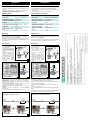
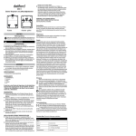
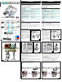
ITALIANO
ENGLISH
Avvertenze
Warning
>Prima dell’uso leggere con attenzione il presente manuale.
>Questo prodotto non va mai collegato ad apparecchiature diverse da
>Non cortocircuitare il connettore di uscita 12Vdc
>Please read the directions carefully before using the tool.
>Do not connect this tool to any other device not specifically
described in this handbook.
>Do not short-circuit the 12Vdc output connector.
Caratteristiche tecniche
Technical data
quelle specificate nel presente manuale.
mod.
UTP-TX12
CH 1
CH 2
A B C D E F G H
1
CLOSED
OPEN
Video input
Nr 1 BNC - 1 Vpp 75 ohm
Video input
Nr 1 BNC - 1 Vpp 75 ohm
Video output
UTP/FTP CAT5/6 AWG24
Video output
UTP/FTP CAT5/6 AWG24
Alimentazione telecamera Spina DC
Camera power supply
DC plug
Distanza di trasmissione
max 80 metri
Transmission distance
max 80 m
Potenza
0W
Power
0W
Temperatura esercizio
-10 °C ÷ +40 °C
Operating temperature
-10 °C ÷ +40 °C
Grado di protezione
IP50
IP Protection
IP50
Dimensioni (LxHxP)
40x22x50 mm
Dimensions (LxHxD)
40x22x50 mm
Peso
27 g
Weight
27 g
Impiego
Utilities
UTP-TX12 è un trasmettitore di segnale video 1 canale che allo stesso
tempo fornisce 12Vdc alla telecamera se abbinato ad uno dei
seguenti ricevitori: UTP-4RX12
Con un solo cavo CAT5 è possibile collegare il segnale video e
l'alimentazione a due telecamere, permettendo di evitare
l'installazione di alimentatori dedicati ad ogni telecamera (fig.1)
UTP-TX12 is a video signal 1 channel transmitter which also
supplies the camera with the DC12V if combined with one of
the following receivers: UTP-4RX12
This allows an easier and faster cable tracing and prevents from the
installation of one dedicated power supply for each camera
(picture1).
Istruzioni per l'uso
Instruction
>Aprire il contenitore allargando
le linguette di aggancio sulla
parte inferiore (fig.3)
>Sguainare il cavo CAT5 per
20mm circa senza tagliare i
conduttori interni (fig. 6).
>Tagliare i conduttori del colore
relativo alla telecamera da
coll egare, seguendo le
indicazioni sull'etichett a
all'interno del contenitore e
f a c e n d o a t t e n zi on e alla
polarità (fig.4)
>Open the case by releasing
the hooking tongues on the
bottom (picture 3).
>Re mo v e th e p ro tec tin g
sheath of CAT5 cable for
about 20mm without cutting
the internal conductors.
>Cut the conductors which
colours correspond to the
camera that has to be
connected following the
instructions on the label
inside the UTO-TX12 and
taking care of right polarity
(picture 4).
CH 1
BLU +
BLU-BIANCO
Parte inf.
3
SCREWDRIVER
2,5 x 0,4 mm
CH 1
+ - + -
BLUE +
BLUE-WHITE
CAT5
SIGNAL 12V
+ - + -
BROWN +
BROWN-WHITE
CHIUSO
CH 2
CAT5
3
CACCIAVITE
2,5 x 0,4 mm
S EGNALE 12V
MARRONE +
MARRONE-BIANCO
VERDE +
VERDE-BIANCO
ARANCIO +
ARANCIO-BIANCO
Bottom
APERTO
GREEN +
GREEN-WHITE
ORANGE +
ORANGE-WHITE
CAVO CAT5
CLOSED
OPEN
CH 2
CAT5 CABLE
CONNETTORE
ETICHETTA INTERNA
2
IN
VIDEO
OUT 12Vdc
(cable provided)
CONNECTOR
5
4
>Spellare i conduttori circa 5mm ed inserirli nel connettore. Chiudere il
morsetto spostando la slitta in posizione CHIUSO (fig 2 e 5) con
l'aiuto di un cacciavite.
>Posizionare il cavo CAT5 in modo che possa uscire dai fori laterali del
contenitore, come mostrato in fig.6.
>Chiudere il contenitore ed eventualmente fissarlo al muro o alla
scatola stagna con una vite.
>Collegare l'alimentazione della telecamera allo spinotto 12Vdc del
UTP-TX12.
>Accendere il ricevitore e verificare l'accensione del LED sul UTP-TX12.
>Collegare il BNC all'uscita video della telecamera.
Preparazione cavo CAT5 e connessioni.
Inner label
5
>Rip the conductors off for about 5mm and insert them in the
connector. Close the terminal changing the slide connector to OFF
position by means of a screwdriver (pictures 2 and 5).
>Place CAT5 cable so that it could come out from the side holes of
the case (see picture 6).
>Close the UTP-TX12 case and place it where you need (fixed to wall or
to a watertight box with a screw).
>Connect the camera power supply to UTP-TX12 12V dc plug.
>Switch on the receiver and check if the UTP-TX12 LED is on.
>Connect the BNC connector to the camera video output.
Preparation CAT5 cable and connections.
20mm
UTP-TX12
4
20mm
UTP-TX12
UTP-TX12
UTP-TX12
receiver
ricevitore
Telecamera 1
Telecamera 2
6
Camera 1
Camera 2
6
ESPAÑO
L
Advertencias
FRANÇAIS
Avertissement
DEUTSC
H
>Por favor lea cuidadosamente las instrucciones antes de usar el
dispositivo.
>No conecte este producto a cualquier otro dispositivo no
específicamente descrito en este manual.
>No ponga en cortocircuito el conector de salida de 12Vdc.
>Lisez attentivement les instructions avant d'utiliser cet appareil.
>Ne connectez pas cet appareil à un autre équipement que celui décrit
Especificaciones
Caractéristiques techniques
dans ce manuel.
>Ne court circuitez pas la connexion de sortie 12 Vdc.
Entrada video
Nr 1 BNC - 1 Vpp 75 ohm
Entrée vidéo
Nr 1 BNC - 1 Vpp 75 ohm
Salida video
UTP/FTP CAT5/6 AWG24
Sortie vidéo
UTP/FTP CAT5/6 AWG24
Alimentación cámara
Conector DC
Distancia de transmisión max 80 m
Alimentation caméra
Connecteur DC
Distance de transmission max 80 m
Potencia
Puissance
0W
Temperatura de funcionamiento -10 °C ÷ +40 °C
Température d'utilisation
-10 °C ÷ +40 °C
Protección
IP50
Niveau de protection
IP50
Dimensiones (LxHxP)
40x22x50 mm
Dimensions (LxHxP)
40x22x50 mm
Peso
27 g
Poids
27 g
0W
Utilización
Applications
El UTP-TX12 es un transmisor de señal de video de 1 canal que
también proporciona a la cámara los 12Vdc si se combina con
uno de lo siguientes receptores: UTP-4RX12.
Esto permite un cableado más fácil y más rápido que previene la
instalación de una fuente de alimentación especializada para cada
cámara (imagen 1).
Le UTP-TX12 est un émetteur de signaux vidéo à 1 canal qui alimente
aussi la caméra avec la tension 12 Vdc en combinaison avec les
récepteurs suivants :UTP-4RX12.
Ceci permet un câblage facile et rapide et rend superflu l'installation
d'une alimentation pour chacune des caméras reliées (image 1).
Instrucciones
Instructions
>Abra la tapa soltando las
lengüetas enganchadas en
el fondo (imagen 3).
>Quite la vaina que protege el
c a b l e d e C A T 5
aproximadamente 20mm sin
cortar los conductores
interiores.
>Corte los conductores del
color que corresponde a la
cámara y tiene que ser
conectado tal como indican
las instrucciones en la
etiqueta dentro del UTPTX12 y teniendo cuidado
sin invertir la polaridad
(imagen 4).
>Ouvrez le boîtier en écartant
les crochets d'attache sur le
dessous (image 3).
>Retirez l'isolation du câble
3
CAT5 sur environ 20mm en
faisant attention de ne pas
a b î me r l e s c o n d u c t e u rs
internes.
>Coupez les conducteurs aux
couleurs correspondantes à la
caméra qui sera connectée en
suivant les instructions qui se
trouvent à l'intérieur du UTPTX12 en en faisant attention
sur la
polarité correcte (image 4).
DESTORNILLADOR
2,5 x 0,4 mm
CH 1
AZUL +
AZUL-BLANCO
MARRON +
MARRON-BLANCO
VERDE
VERDE -BLANCO
NARANJA +
NARANJA-BLANCO
TOURNEVIS
2,5 x 0,4 mm
CH 1
SEÑAL 12V
BLEU +
BLEU-BLANC
+ - + -
SIGNAL 12V
+ - + -
MARRON +
MARRON-BLANC
CERRADO
ABIERTO
CH 2
Fermé
Ouvert
CH 2
VERT +
VERT-BLANC
ORANGE +
ORANGE-BLANC
CABLE CAT5
CABLE CAT5
CONECTOR
Etiqueta interna
CONNECTEUR
4
5
>Quite el plástico de los conductores aproximadamente 5mm e
insértelos en el conector. Cierre el terminal cambiando la posición
del conector a CERRADO por medio de un destornillador
(imágenes 2 y 5).
>Coloque el cable CAT5 para que pueda salir por los agujeros
laterales de la caja (imagen 6).
>Cierre la caja del TA1 y colóquelo donde lo necesite (con un tornillo
fijo a la pared directamente o en una caja estanca).
>Conecte la alimentación de la cámara al conector de 12Vdc del
UTP-TX12.
>Encender el receptor y averiguar que el LED de UTP-TX12
sea encendido.
>Conecte el conector BNC a la salida de video de la cámara.
Etiquette intérieure
>Dénudez les conducteurs sur environ 5mm et introduisez-les dans le
connecteur. Verrouillez le terminal en faisant glisser le connecteur en
position FERME à l'aide d'un tournevis (images 2 et 5).
>Positionnez le câble CAT5 de façon à ce qu'il ressorte des trous
latéraux du boîtier (voir image 6).
>Refermez le boîtier du UTP-TX12 et fixez-le à sa place (attaché à un
mur ou
dans un conteneur étanche).
>Connectez l'alimentation de la caméra au connecteur 12Vdc du UTPTX12.
>Allumez le récepteur et controlez l'allumage du LED sur le UTP-TX12.
>Branchez le connecteur BNC à la sortie vidéo de la caméra.
20 mm
20 mm
TA1
TA1
receptor
Cámara 1
5
4
Préparation du câble CAT5 et connexions.
Preparación cable CAT5 y conexiones.
TA1
3
3
Càmara 2
TA1
recepteur
Camara 1
Camara 2
4
5