1
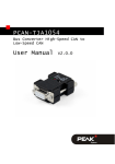
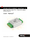
Fiber optic
connectors
Splice tray
(JPM440A, not
included)
Fiber optic cable
Fiber adapter panel
with 6 fiber optic
connectors installed
Figure 2. The JPM406A-R5 with three fiber adapter panels visible (up to nine more
can be stacked beneath the visible ones, for a total of 12 adapter panels).
The fiber cable is routed through the splice tray,
then terminated via the fiber optic connectors.
TRADEMARKS USED IN THIS MANUAL
Black Box and the Double Diamond logo are registered trademarks of BB Technologies, Inc.
Kevlar is a registered trademark of E.I. du Pont de Nemours and Company.
PLEXIGLAS is a registered trademark of Roehm GmbH & CO.
Any other trademarks mentioned in this manual are acknowledged to be the property of the trademark owners.
© Copyright 2009. Black Box Corporation. All rights reserved.
1000 Park Drive
•
Lawrence, PA 15055-1018
•
724-746-5500
•
Fax 724-746-0746
FEBRUARY 2009
JPM406A-R5
JPM418A-R4
Fiber Rackmount Cabinet
CUSTOMER
SUPPORT
INFORMATION
Order toll-free in the U.S.: Call 877-877-BBOX (outside U.S. call 724-746-5500)
FREE technical support 24 hours a day, 7 days a week: Call 724-746-5500 or fax 724-746-0746
Mailing address: Black Box Corporation, 1000 Park Drive, Lawrence, PA 15055-1018
Web site: www.blackbox.com • E-mail: [email protected]
FIBER RACKMOUNT CABINET
1. Specifications
Construction: 16-gauge, cold-rolled steel
Size: JPM406A-R5: 5.25"H (3U) x 17"W x 11.5"D (13.3 x 43.2 x 29.2 cm);
JPM418A-R4: 3.5"H (2U) x 17"W x 11"D (8.9 x 43.2 x 27.9 cm)
Weight: JPM406A-R5: 17.2 lb. (7.8 kg); JPM418A-R4: 15.2 lb. (6.9 kg)
2. Overview
The JPM406A-R5 is 3U high, fits in a 19" or 23" rack, and supports 12 adapter panels. (Each adapter panel has
up to 12 connectors, for a maximum of 144 ports.) It provides termination for optical cables on the premises or
in a central office. The JPM418A-R4 is only 2U high and supports six adapter panels; it also fits in a 19" or
23" rack. (Each adapter panel has up to 12 connectors, for a maximum of 72 ports.)
The Fiber Rackmount Cabinets are constructed of 16-gauge cold-rolled steel, and they’re compact and rugged
enough for commercial applications. Its powder-coated finish is corrosion resistant.
The cabinet has a front door, a rear door, and outside and inside plant cable entry/exit holes. Up to 3 splice
trays (JPM440A, not included) can be mounted in the chassis. One splice tray accepts four fusion (for singlemode fiber) or four mechanical (for multimode fiber) splice modules.
Two cable-entry holes at the right and left on the cabinet’s rear and two patch cord exit holes in the front
bottom make cable installation easy.
Your package should include the following items. If anything is missing or damaged, contact Black Box at
724-746-5500.
• (1) Fiber Rackmount Cabinet
• (1) Kevlar® clamp (installed)
• (4) 12⁄24 cup-head screws
• (4) 10⁄32 cup-head screws
• (30) 3" (7.6-cm) cable ties
• (4) 4" (10.2-cm) cable ties
• (6) rectangular plastic cable holders
• (1) “danger” sticker
• (3) pairs of black spool rings (installed) for
JPM406A-R5 or (2) pairs of black spool rings (installed)
for JPM418A-R4
• (1) locking PLEXIGLAS® door
• (2) mounting brackets
• (4) silver screws for mounting brackets
• (1) set of keys
• (4) washers for mounting brackets
• (1) users’ manual
• (1) identification label sticker
2
FIBER RACKMOUNT CABINET
3. Installation
1. Attach the two mounting brackets to the cabinet, and secure them with the four silver screws and four
washers.
2. Using the 10⁄32 or 12⁄24 cup-head screws, mount the Fiber Rackmount Cabinet in a 19" or 23" rack.
3. Open the back door by pulling, then releasing, the locking buttons.
4. Route multi-strand fiber cable (not included) through the rectangular openings on the cabinet’s top,
bottom, or through the rubber grommets on the side.
5. Use the Kevlar clamp to secure the multi-strand fiber to the cabinet. Loosen the Kevlar clamp’s two screws
and wrap the cable’s Kevlar yarn around the clamp. Tighten the screws to secure the multi-strand fiber to
the cabinet.
NOTE
The Kevlar clamp can be mounted on the cabinet’s rear left or right.
6. Install the cabinet’s PLEXIGLAS front door.
7. Pull out the tray (see Figure 1) to install a fiber adapter and splice tray (if needed). Up to 12 fiber adapters
can be installed in the JPM406A-R5; up to six can be installed in the JPM418A-R4.
8. Install the connectors on the multi-strand fiber cable, or make the splice as needed. (See Figure 2 for a
typical cable installation.) Connect the fiber cable to the fiber adapters.
9. Use the included rectangular plastic cable holders, cable ties, and black spool rings to hold the cable in
place inside the cabinet.
10. Slide the tray back into place inside the cabinet.
11. Close the cabinet’s rear door.
12. Snap in the 1" (2.5-cm) rectangular cable holder in the front of the inside tray. This helps organize the
fiber patch cables used in the front of the cabinet.
13. Close the cabinet’s front PLEXIGLAS door. Push the buttons in, then release, to lock.
14. Attach the “danger” sticker to the cabinet’s rear or top panel.
15. Attach the identification label sticker to the cabinet’s rear door.
Install the fiber
adapters here
Rectangular
openings
Splice tray
Kevlar clamp
installed on the
side rear corner
Rectangular cable
holders
Inside
tray
Figure 1. Fiber Rackmount Cabinet with tray pulled out.
3